

Page 1
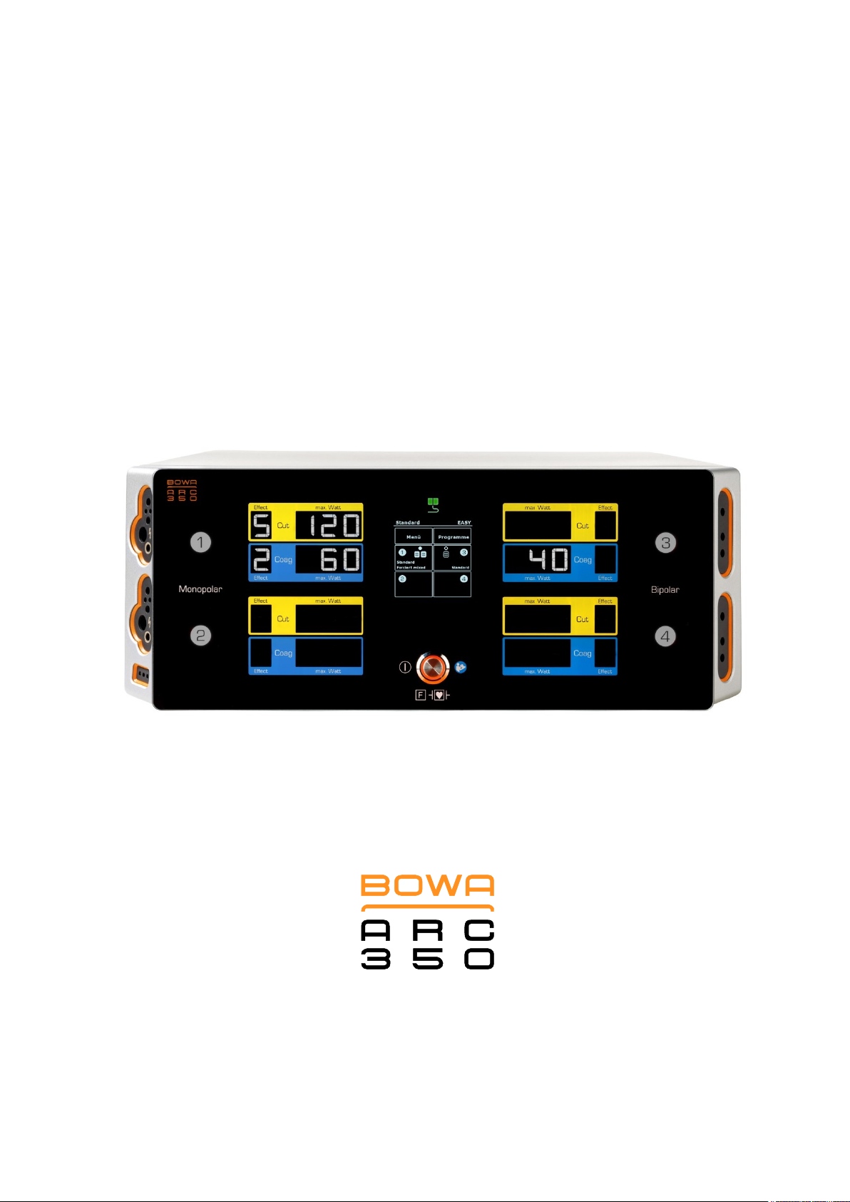
OPERATING MANUAL
ELECTROSURGICAL UNIT
Page 2

2 Operating Manual ARC 350 900-351_IFU_V2.0.0_20221-S0-20150520-EN
Page 3

Contents
Contents
1. Using this operating manual .......................................................................................................... 7
1.1. Revision index .................................................................................................................... 7
1.2. Validity ................................................................................................................................ 7
1.3. Other applicable documents .............................................................................................. 7
1.4. Icons and labeling .............................................................................................................. 7
1.4.1. Structure of warning instructions ........................................................................ 7
1.4.2. Risk levels in warning instructions ...................................................................... 8
1.4.3. Tips ..................................................................................................................... 8
1.4.4. Other symbols and marks ................................................................................... 8
2. Safety ................................................................................................................................................ 9
2.1. Intended use ...................................................................................................................... 9
2.2. General safety instructions .............................................................................................. 10
2.3. Personal safety instructions ............................................................................................. 11
2.3.1. Ambient conditions ........................................................................................... 11
2.3.2. Patients with pacemakers ................................................................................. 11
2.3.3. Hazard-free patient positioning ......................................................................... 12
2.3.4. Correct connection of the HF device ................................................................ 12
2.3.5. Correct use of the HF device ............................................................................ 12
2.3.6. Configuring HF device settings and using accessories .................................... 13
2.4. Product-related safety instructions ................................................................................... 14
2.5. Safe handling (general instructions) ................................................................................ 14
2.5.1. Operation area: avoiding ignition and explosions ............................................. 15
2.5.2. Applying the neutral electrode .......................................................................... 15
3. Description ..................................................................................................................................... 18
3.1. User interface components .............................................................................................. 18
3.1.1. Front panel user interface components ............................................................ 18
3.1.2. Monopolar connector module (left) ................................................................... 18
3.1.3. Bipolar connector module (right) ...................................................................... 19
3.1.4. Rear panel user interface components ............................................................. 20
3.2. Symbols used on the device ............................................................................................ 21
3.2.1. Rating label ....................................................................................................... 22
3.3. Scope of delivery .............................................................................................................. 22
3.4. Components required for operation ................................................................................. 22
3.5. Operating conditions ........................................................................................................ 22
900-351_IFU_V2.0.0_20221-S0-20150520-EN Operating Manual ARC 350 3
Page 4

4. Prearrangement ............................................................................................................................. 23
4.1. Setting up the HF device .................................................................................................. 23
4.2. Switching on the HF device ............................................................................................. 24
4.3. Connecting instruments ................................................................................................... 24
4.3.1. Instruments for monopolar use ......................................................................... 25
4.3.2. Instruments for bipolar applications .................................................................. 25
4.3.3. Connecting a foot switch................................................................................... 25
4.4. Functional test .................................................................................................................. 26
4.4.1. Auto test function .............................................................................................. 26
4.4.2. Functional testing .............................................................................................. 26
4.4.3. Actions in case of problems .............................................................................. 27
4.5. Neutral electrode monitoring ............................................................................................ 27
4.5.1. General information .......................................................................................... 27
Contents
4.5.2. EASY neutral electrode monitoring (EASY monitoring) ................................... 28
5. Operation ........................................................................................................................................ 29
5.1. Connecting power ............................................................................................................ 29
5.2. Program overview ............................................................................................................ 29
5.2.1. Display .............................................................................................................. 30
5.3. Activating and deactivating connectors............................................................................ 31
5.4. Configuring output currents .............................................................................................. 31
5.4.1. Selecting the mode ........................................................................................... 31
5.4.2. Specifying power limits ..................................................................................... 33
5.4.3. Selecting the effect ........................................................................................... 33
5.4.4. Assigning the foot pedal ................................................................................... 34
5.4.5. Selecting the neutral electrode ......................................................................... 35
5.4.6. Plug’n Cut COMFORT ...................................................................................... 37
5.5. Mode overview ................................................................................................................. 38
5.5.1. Monopolar modes ............................................................................................. 38
5.5.2. Bipolar modes ................................................................................................... 39
5.6. Monopolar cutting modes ................................................................................................. 40
5.6.1. Standard ........................................................................................................... 40
5.6.2. Micro ................................................................................................................. 40
5.6.3. Dry .................................................................................................................... 40
5.6.4. Argon ................................................................................................................ 41
5.6.5. Resection .......................................................................................................... 41
5.6.6. MetraLOOP ....................................................................................................... 42
4 Operating Manual ARC 350 900-351_IFU_V2.0.0_20221-S0-20150520-EN
Page 5

Contents
5.6.7. Laparoscopy ..................................................................................................... 42
5.6.8. GastroLOOP 1 (optional) .................................................................................. 42
5.6.9. GastroLOOP 2 (optional) .................................................................................. 43
5.6.10. GastroLOOP 3 (optional) .................................................................................. 43
5.6.11. GastroKNIFE 1 (optional) ................................................................................. 44
5.6.12. GastroKNIFE 2 (optional) ................................................................................. 44
5.6.13. GastroKNIFE 3 (optional) ................................................................................. 45
5.7. Monopolar coagulation modes ......................................................................................... 45
5.7.1. Moderate ........................................................................................................... 45
5.7.2. Forced coag ...................................................................................................... 46
5.7.3. Forced mixed .................................................................................................... 46
5.7.4. Forced cutting ................................................................................................... 46
5.7.5. Spray................................................................................................................. 47
5.7.6. Argon open ....................................................................................................... 47
5.7.7. Argon flexible (optional) .................................................................................... 48
5.7.8. Argon flex. pulse (optional) ............................................................................... 48
5.7.9. Resection .......................................................................................................... 49
5.7.10. Cardiac Mammary ............................................................................................ 49
5.7.10. Cardiac Thorax ................................................................................................. 49
5.7.11. SimCoag ........................................................................................................... 50
5.7.12. Gastro Coag (optional) ..................................................................................... 50
5.7.13. Laparoscopy ..................................................................................................... 50
5.8. Bipolar cutting modes ....................................................................................................... 51
5.8.1. Standard ........................................................................................................... 51
5.8.2. Bipolar resection (optional) ............................................................................... 51
5.8.3. Bipolar scissors ................................................................................................. 52
5.9. Bipolar coagulation modes ............................................................................................... 52
5.9.1. Standard forceps .............................................................................................. 52
5.9.2. Standard forceps AUTO ................................................................................... 52
5.9.3. Micro forceps .................................................................................................... 53
5.9.4. Forceps forced .................................................................................................. 53
5.9.5. LIGATION (optional) ......................................................................................... 54
5.9.6. TissueSeal PLUS (optional) ............................................................................. 54
5.9.7. Bipolar scissors ................................................................................................. 55
5.9.8. Laparoscopy ..................................................................................................... 55
5.9.9. Bipolar resection (optional) ............................................................................... 55
900-351_IFU_V2.0.0_20221-S0-20150520-EN Operating Manual ARC 350 5
Page 6

5.10. Menu dialogs .................................................................................................................... 56
5.10.1. Overview ........................................................................................................... 56
5.10.2. "System Settings" dialog ................................................................................... 56
5.10.3. “Neutral electrode“ dialog ................................................................................. 57
5.10.4. “Program“ dialog ............................................................................................... 58
5.10.5. “Language“ dialog ............................................................................................. 60
5.10.6. "System messages" dialog ............................................................................... 60
5.10.7. “System information“ dialog .............................................................................. 61
5.10.8. "Service" dialog ................................................................................................. 61
5.10.9. "Argon" dialog ................................................................................................... 63
6. Detecting and correcting faults ................................................................................................... 64
6.1. System informations ......................................................................................................... 64
6.2. Fault indications for EASY monitoring ............................................................................. 69
Contents
7. Preparation ..................................................................................................................................... 70
7.1. Preparation of the accessories ........................................................................................ 70
7.2. Disinfection and cleaning ................................................................................................. 70
8. Maintenance and repair ................................................................................................................ 71
8.1. Maintenance ..................................................................................................................... 71
8.1.1. Safety inspection .............................................................................................. 71
8.2. Repairs ............................................................................................................................. 72
9. Storage ........................................................................................................................................... 73
9.1. Technical service ............................................................................................................. 73
10. Technical specifications ............................................................................................................... 74
10.1. ARC 350 technical data ................................................................................................... 74
10.2. Output, voltage and current diagrams .............................................................................. 81
11. Accessories and replacement parts .......................................................................................... 119
12. EMC ............................................................................................................................................... 120
12.1. Guidelines and manufacturer’s declaration in accordance with IEC 60601-1-2
Section 6.8.3.201 ........................................................................................................... 120
13. Disposal ........................................................................................................................................ 123
6 Operating Manual ARC 350 900-351_IFU_V2.0.0_20221-S0-20150520-EN
Page 7
1 Using this operating manual
Unit version
Last revised
Valid from version 2.0.0
2014/02
SIGNAL WORD
"Risk type, source and consequences there of" (Personal injury)!
Measure for risk prevention.
NOTE
"Risk type, source and consequences there of" (Property damage)!
Measure.
1. Using this operating manual
This operating manual is part of the device.
BOWA-electronic GmbH & Co. KG, referred to in the following simply as BOWA,
assume no liability nor provide any warranty whatsoever for damage and
consequential damages that arise due to non-compliance with the operating
manual.
Read the operating manual carefully and thoroughly before using this device.
Store the operating manual in a safe place throughout the service life of the
device.
Keep the operating manual accessible to operating room personnel.
Give the operating manual to each successive owner and/or user of this
device.
Always update the operating manual whenever you receive additional
information from the manufacturer.
1.1. Revision index
1.2. Validity
This operating manual applies only to the devices designated on the title page.
1.3. Other applicable documents
Comply with other applicable documents in the appendix or in the other
sections.
1.4. Icons and labeling
1.4.1. Structure of warning instructions
900-351_IFU_V2.0.0_20221-S0-20150520-EN Operating Manual ARC 350 7
Page 8
1 Using this operating manual
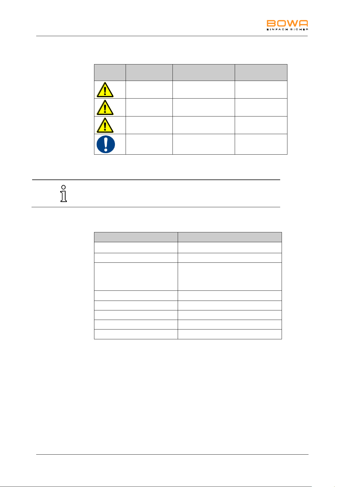
Symbol
Risk level
Probability of
occurrence
Consequences of
non-compliance
DANGER
Immediate risk
Death, serious
injuries
WARNING
Possible risk
Death, serious
injuries
CAUTION
Possible risk
Minor injuries
NOTE
Possible risk
Property damage
Tips and additional information to facilitate tasks
Symbol or mark
Meaning
Prerequisite for an activity
Activity with one step
1.
2.
3.
Activity with several steps in a binding
sequence
Result of preceding activity
List (first level)
List (second level)
Emphasis
Emphasis
......, see Section xxx, page xxx
Cross reference
1.4.2. Risk levels in warning instructions
1.4.3. Tips
1.4.4. Other symbols and marks
8 Operating Manual ARC 350 900-351_IFU_V2.0.0_20221-S0-20150520-EN
Page 9

2 Safety
BOWA requires that the HF device is operated under the supervision of
qualified and authorized personnel. The surgeon and medical staff must
be trained in the fundamental principles, rules for use and risks of HF
surgery and must be familiar with these in order to safely and reliably
prevent putting patients, staff and equipment at risk.
Contact your BOWA distributor for trainings and training material.
Any other use is neither intended nor proper and must be effectively
prevented.
2. Safety
2.1. Intended use
The HF device is intended exclusively for the generation of electrical power for
monopolar and bipolar cutting and coagulation on tissue structures in surgical
operations.
It is used in the following areas:
General surgery
Endoscopy (GastroCut mode)
Gynecology
Hand surgery
ENT
Cardiac surgery (including open-heart surgery)
Neurosurgery
Paediatric surgery
Plastic surgery and dermatology
Thoracic surgery
Orthopedics
Urology, including transurethral resection (TUR)
Do not use the HF device if, in the opinion of an experienced physician or
according to current professional literature, such use would endanger the patient,
due for example to the general condition of the patient, or if other contraindications
are present.
900-351_IFU_V2.0.0_20221-S0-20150520-EN Operating Manual ARC 350 9
Page 10

2 Safety
To protect personnel, BOWA recommends the use of a smoke evacuator
to extract electrosurgical smoke, e.g. BOWA SHE SHA.
2.2. General safety instructions
Ensure that no electronic devices that are subject to interference from
electromagnetic fields are set up in the vicinity of the HF device.
Observe the instructions on electromagnetic compatibility provided in section
EMC, page 120.
Always connect the HF device to a mains power system with a protective
earth lead in order to prevent electric shock.
Additional devices that are connected to electrical medical devices must satisfy
relevant IEC or ISO standards (e.g. IEC 60950 for data processing devices).
Furthermore, all configurations must comply with the standardised requirements
for medical systems (see IEC 60601-1-1 or Section 16 of the 3rd edition of
IEC 60601-1 as relevant). Anyone who connects additional devices to electrical
medical devices is automatically a system configurator and thus responsible for
meeting standardised system requirements. Please note that local laws prevail
over the aforementioned standard requirements. In case of questions, please
contact your local dealer or Technical Service, see section Technical service,
page 73.
10 Operating Manual ARC 350 900-351_IFU_V2.0.0_20221-S0-20150520-EN
Page 11
2 Safety
2.3. Personal safety instructions
2.3.1. Ambient conditions
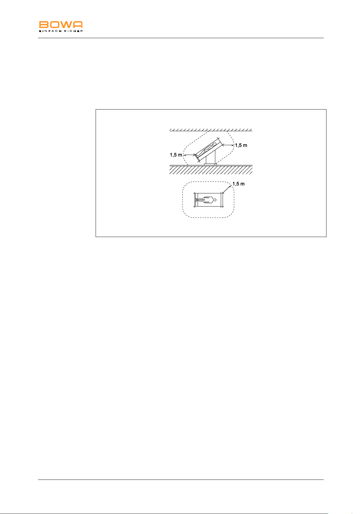
Do not use the HF device in the immediate vicinity of the patient. Observe the
minimum distances recommended by BOWA, as shown in the following
figure.
2.3.2. Patients with pacemakers
Malfunction or destruction of the pacemaker can endanger the life of the patient or
result in irreversible injuries to the patient.
In the case of patients with pacemakers, consult the cardiologist before
carrying out HF surgery.
Use bipolar HF methods.
Attach the HF neutral electrode close to the operating field.
Set the demand pacemaker to a fixed frequency.
Ensure that the pacemaker does not come into contact with the HF electrode.
Keep a fully operational defibrillator within reach.
Carry out a postoperative pacemaker check.
900-351_IFU_V2.0.0_20221-S0-20150520-EN Operating Manual ARC 350 11
Page 12

2 Safety
2.3.3. Hazard-free patient positioning
Position patients so that they are not touching any metal parts that are
grounded or have considerable capacitance relative to ground (e.g. operating
table brackets). If necessary, place anti-static cloths between the patient and
the bedding.
Ensure that the patient does not touch any wet clothes or bedding.
Place anti-static cloths between areas with heavy sweating and skin-to-skin
contact areas on the patient’s torso.
Ensure that the patient is resting on a suitable surface in order to prevent
pressure necrosis.
Drain urine via a catheter.
2.3.4. Correct connection of the HF device
Always ground the HF device to the equipotential rail.
Also observe the requirements in Section 8.6.7 of IEC 60601-1 regarding
medical electrical systems.
Do not use needle electrodes for monitoring.
Attach electrodes of physiological monitoring devices without protective
resistors or HF chokes as far away from the HF electrodes as possible.
Place lines from monitoring devices so that they do not lie on the patient’s
skin.
Keep the leads to the HF electrodes as short as possible and position them
so that they do not touch the patient or other leads.
Do not place any objects on the HF device.
2.3.5. Correct use of the HF device
Inadvertent activation of the HF device outside the user’s field of vision can injure
the patient.
Activate the HF device only when the electrode is in your field of vision and
you can quickly deactivate the HF device at all times.
If the HF device is activated inadvertently, switch it off immediately using the
on/off switch.
Take particular care when using a foot switch or manual switch.
Improper preparation, user errors or faults in the HF device can cause damage to
the HF device.
Use the automatic monitoring functions to ensure that the HF device is
working properly. See Section Functional testing, page 26 for information on
the auto test functions.
Ensure that no conductive fluids (e.g. blood or amniotic fluid) have penetrated
the foot switch or the manual switch.
Ensure that the cables for the foot switch and the manual switch are free from
short circuits and broken leads.
12 Operating Manual ARC 350 900-351_IFU_V2.0.0_20221-S0-20150520-EN
Page 13

2 Safety
2.3.6. Configuring HF device settings and using accessories
Setting the output power too high can injure the patient. Therefore, before you
increase the output power, ensure that:
the neutral electrode is attached properly;
the working electrodes are clean;
the plug connections are all correct.
Setting the HF device correctly
To prevent inadvertent (thermal) tissue damage during operations on body
parts with small cross sections and in areas with high resistance (bones or
joints), use the bipolar method in these areas.
Set the level of the acoustic signal that sounds when the electrode is
activated so that it is always clearly audible.
Risk of nerve or muscle excitation by low-frequency currents.
During HF surgical operations (especially when an arc is formed), part of the HF
current is converted into a low-frequency current. This current can trigger muscle
contractions in the patient.
To minimize the risk of injury to the patient, set the power and the effect as
low as possible.
Correct use of accessories
Use only insulated accessories.
Check all electrodes for sharp edges and projecting parts before use.
Use only electrodes that are free of defects and in good working order.
Never place active electrodes on or near the patient.
Do not remove hot electrodes from the patient’s body directly after cutting or
coagulation.
Ensure that there is sufficient distance between the patient cables and the
cables of the HF device.
Do not run the patient cable across the patient.
900-351_IFU_V2.0.0_20221-S0-20150520-EN Operating Manual ARC 350 13
Page 14

2 Safety
2.4. Product-related safety instructions
Devices manufactured by BOWA are developed in accordance with the current
state of technology and generally accepted safety rules. Despite this, using these
products can lead to risks to the life and health of the user or third parties and/or
damage to the device or other objects.
Use only accessories approved by BOWA, see Section Accessories and
replacement parts, page 119.
Use the device only when it is in free of technical defects and in good working
order and only for the intended purpose, always remaining aware of safety
requirements and risks and complying with this operating manual.
Have malfunctions that can adversely affect safety (e.g. deviations from the
permissible operating conditions) repaired without delay.
Wipe down the HF device only with cleaning agents and disinfectants that are
approved in the country of use for surface cleaning. See Section Disinfection
and cleaning, page 70.
Never immerse the device in water or cleaning agents.
Never boil the device and never disinfect it mechanically.
If any fluids penetrate the device, drain them immediately.
Damage to the device can lead to an undesirable increase in output power due to
improper operation of the device.
Certain units or accessories can cause danger in lower power settings. For
example, the risk of gas embolism in argon assisted coagulation rises, if the hfpower is insufficient for the fast creation of an impenetrable eschar layer on the
target tissue.
2.5. Safe handling (general instructions)
Before each use of the device, check to ensure that it is functioning properly
and is in good working order and connected properly.
Observe the instructions on intended use in conformance with standards (see
Section Fault indications for EASY monitoring , page 69.
During use, always observe and comply with the acoustic signals and/or error
messages of the HF device (see Section Fault indications for EASY
monitoring , page 69).
The device and accessories may be operated and used only by people who
have the necessary training, knowledge and experience.
Regularly inspect the accessories, especially the electrode cables,
endoscopic accessories and neutral electrodes, for damage to the insulation,
proper operation and expiration date.
Ensure that no instruments are being cleaned when AUTOSTART is
activated.
Wear suitable gloves during operations.
14 Operating Manual ARC 350 900-351_IFU_V2.0.0_20221-S0-20150520-EN
Page 15

2 Safety
Observe the instructions on the use of the neutral electrode in the user
guide and the information on the package of the neutral electrode.
2.5.1. Operation area: avoiding ignition and explosions
Sparks are generated when the HF device is used as intended.
Do not use the HF device in areas where there is a risk of explosion.
Do not use any flammable or explosive liquids.
If the display fails, do not use the HF device any longer.
During operations (e.g. in the head or thoracic regions), avoid using ignitable
anesthetics and gases that support combustion (e.g. nitrous oxide or oxygen)
or extract them using a vacuum system.
Use exclusively non-flammable cleaning agents, disinfectants and solvents
(for adhesives). If you use flammable cleaning agents, disinfectants or
solvents, ensure that they have fully evaporated before using HF surgical
equipment.
Ensure that no flammable liquids collect beneath the patient or in body
cavities (e.g. the vagina). Suction and/or flush body cavities before activating
the device.
Wipe off all liquids before using the HF device.
Ensure that no ignitable endogenous gases are present.
Ensure that all materials saturated with oxygen (e.g. cotton or gauze) are kept
far enough away from the HF environment that they cannot ignite.
2.5.2. Applying the neutral electrode
In the monopolar HF method, the neutral electrode feeds the current introduced
into the patient’s body at the surgical site back to the HF device.
To prevent a rise in temperature at the current exit point, the following
conditions must be ensured:
sufficiently large contact surface between the neutral electrode and
the patient’s body;
high electrical conductivity between the neutral electrode and the
patient’s body.
900-351_IFU_V2.0.0_20221-S0-20150520-EN Operating Manual ARC 350 15
Page 16

2 Safety
To prevent the patient being burned by the neutral electrode, you must
comply with the following conditions:
Select the application point for the neutral electrode so that the
current paths between the active and neutral electrodes are as
short as possible and run longitudinally or diagonally through the
patient’s body (because muscles are more conductive in the
direction of the fibrils).
Figure 2-1: Application point of neutral electrode
For surgery in the thoracic region, do not run the current path
transversely across the patient’s body and ensure that the patient’s
heart is never in the current path.
Depending on the surgical site, apply the neutral electrode to the
nearest upper arm or thigh if possible, but never closer than 20 cm.
In the case of self-adhesive disposable electrodes, comply with any
further manufacturer instructions regarding the point of application.
Ensure that the application area is free of scar tissue, bony
protuberances, surface hair and ECG electrodes.
Ensure that there are no implants (e.g. bone nails, bone plates or
endoprostheses) in the current path.
Ensure that no short circuits can occur at the neutral electrode
connection.
Avoid areas where fluids may collect.
Use split neutral electrodes with a sufficiently large surface area
(patient age and max. output power during operation have to be
considered).
Before applying the neutral electrode
Shave the area where the neutral electrode will be applied.
Clean the application site, but do not use any alcohol, since it dries out the
skin and increases the contact resistance.
If the patient has poor circulation, massage or brush the application site.
16 Operating Manual ARC 350 900-351_IFU_V2.0.0_20221-S0-20150520-EN
Page 17

2 Safety
See Section Fault indications for EASY monitoring, page 69 regarding
monitoring of the neutral electrode.
Attach the neutral electrode over the entire contact surface evenly. Secure
reusable neutral electrodes with rubber bands or elastic straps so that they do
not loosen when the patient moves. Ensure that the patient’s circulation is not
impaired (risk of necrosis).
Never use wet clothes or conductive pastes.
Ensure that no liquids (e.g. cleaning fluids, disinfectants, blood or urine)
penetrate between the patient and the neutral electrode.
Do not place the neutral electrode under the patient’s buttocks or back.
Ensure that there are no ECG electrodes in the current path of the HF device.
Check the neutral electrode before and after use for damage and to ensure
that they are working properly.
Replace defective accessories immediately
Example application using a disposable electrode
Remove the protective film and attach the self-adhesive disposable electrode
to the patient. Ensure that the long edge of the disposable electrode faces the
operation site and the electrode is fully in contact with the skin. This avoids
excessive current concentration on the short edge.
Using both hands, press the self-adhesive disposable electrode firmly against
the patient’s skin.
Clamp the electrode tab to the neutral electrode cable.
After the operation, remove the disposable electrode carefully to avoid skin
damage.
With a one-piece neutral electrode
Check the one-piece neutral electrode during surgery.
Ensure that the one-piece electrode is not blocked at the device.
With a split neutral electrode
Apply the split neutral electrode correctly and without any additional objects,
as otherwise the HF device may detect a path between the two sections due
to other objects.
See that the current flows equally to both parts of the split neutral electrode.
900-351_IFU_V2.0.0_20221-S0-20150520-EN Operating Manual ARC 350 17
Page 18
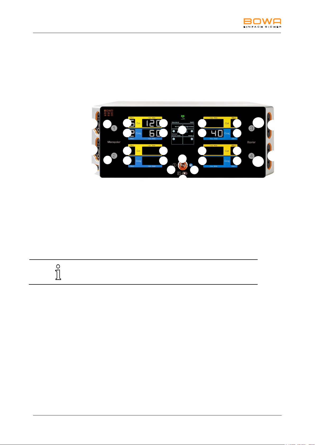
3 Description
While activating an instrument, the Activation indication of the
corresponding socket illuminates yellow or blue.
1
2 4 9 5 6 7 8
10
11 3 15
16
6 6 6
7 7 7
7
7
7 7 6
6 6 6
12
13
14
3. Description
3.1. User interface components
3.1.1. Front panel user interface components
1 On/-Off button
2 "CF-type device with defibrillation protection" icon
3 "Observe use instructions" icon
4 Touchscreen
6 Button Effect
7 Button maximum output power
8 Activation indication Monopolar 1
9 Activation indication Monopolar 2
10 Activation indication Bipolar 3
11 Activation indication Bipolar 4
3.1.2. Monopolar connector module (left)
12 Monopolar 1
Socket connector for monopolar instruments with hand or foot
switch*
13 Monopolar 2
Socket connector for monopolar instruments with hand or foot switch*
11 Socket connector for neutral electrode *
* Applied part type F according to IEC 60601-1
18 Operating Manual ARC 350 900-351_IFU_V2.0.0_20221-S0-20150520-EN
Page 19
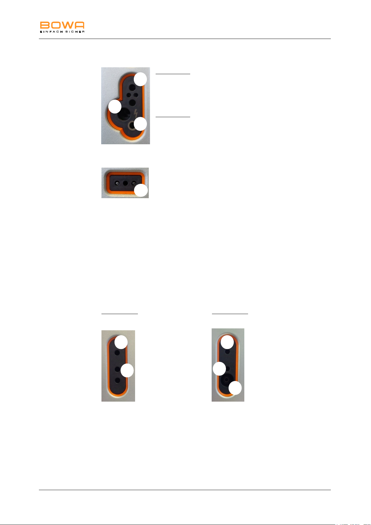
3 Description
c b a
14
b b a
a
c
Monopolar connection sockets
Alternative 1
a BOWA COMFORT
3-Pin US type
b Bovie (footswitch)
c 4 mm Socket (footswitch)
Alternative 2
a BOWA COMFORT
3-Pin US type
b Erbe 5 mm
c 4 mm socket (footswitch)
Connection socket for neutral electrode
14 Neutral (US type)
3.1.3. Bipolar connector module (right)
15 Bipolar 3
Socket connector for bipolar instruments with foot switch, finger switch or
AUTOSTART*
16 Bipolar 4
Socket connector for bipolar instruments with foot switch, finger switch or
AUTOSTART*
Bipolar connection sockets
Alternative 1: Alternative 2:
a BOWA COMFORT a BOWA COMFORT
b 2-pin US type (28.58 mm) b 2-pin US type (28.58 mm)
c Erbe VIO/ICC
* Applied part type F according to IEC 60601-1
900-351_IFU_V2.0.0_20221-S0-20150520-EN Operating Manual ARC 350 19
Page 20
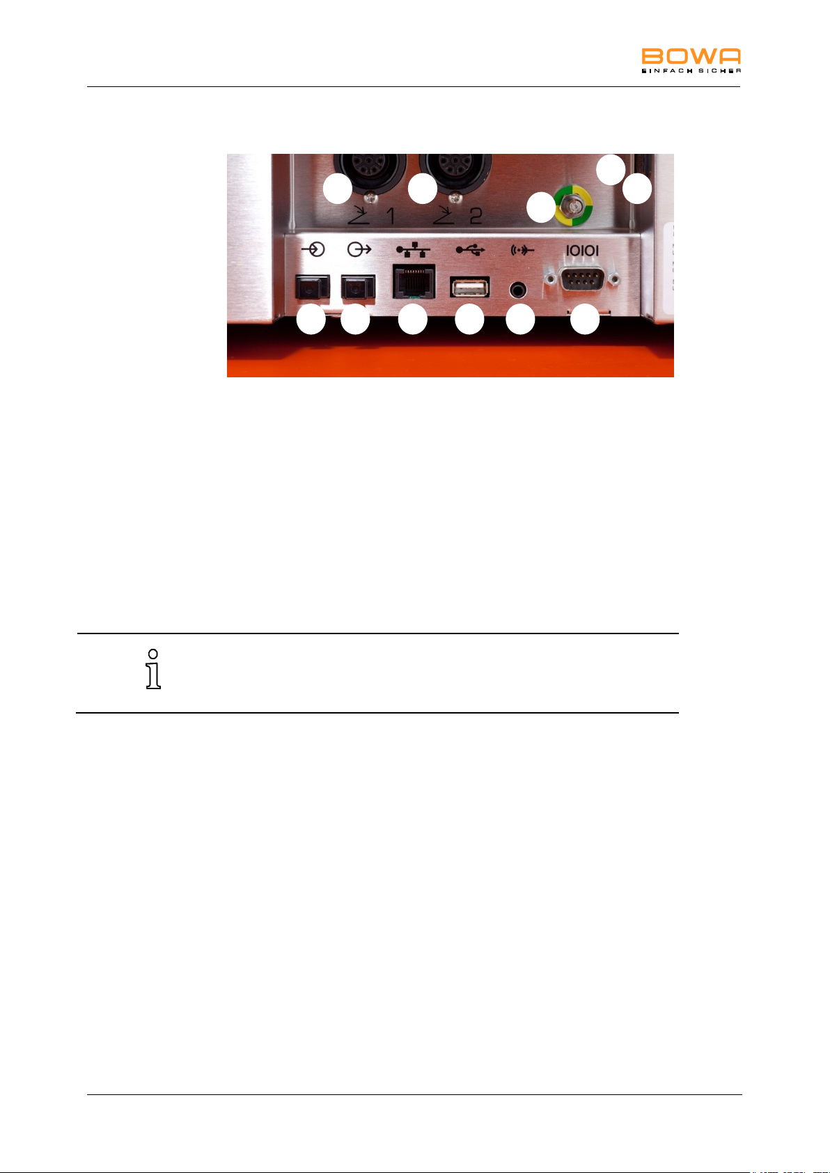
3 Description
The USB connector can be used to perform software updates.
The maximum voltage at the SIP/SOP ports is 15 VDC.
17
18
19
20
21
22
23
24
25
26
27
3.1.4. Rear panel user interface components
17 Foot switch socket connector 1
18 Foot switch socket connector 2
19 Equipotential bonding terminal
20 IEC power cord connector
21 Fiber-optic signal input connector
22 Fiber-optic signal output socket connector
Use the following connections only for service and training purposes:
23 Ethernet connector
24 USB connector
25 Audio In (not occupied)
26 UART communication interface
27 Power switch
20 Operating Manual ARC 350 900-351_IFU_V2.0.0_20221-S0-20150520-EN
Page 21
3 Description
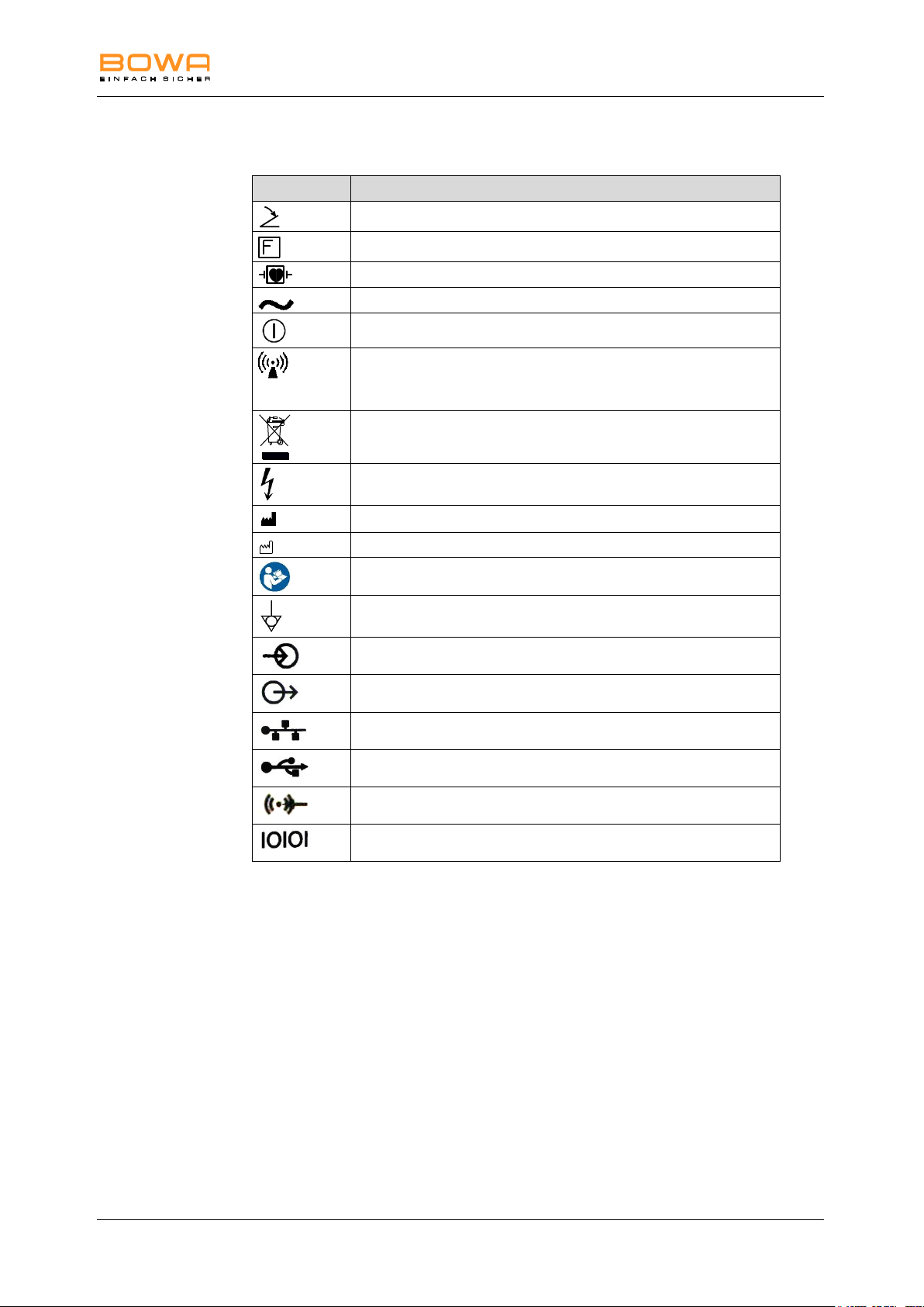
Symbol
Designation
Foot switch connector
Neutral electrode isolated from ground for HF
CF-type device with defibrillation protection
Alternating current
On/off button
During activation (of the HF device) RF energy in the radio
frequency range 9 kHz to 400 GHz is applied, which
produces electromagnetic radiation.
Labeling of electrical and electronic devices in accordance with
Directive 2002/96/EC (WEEE); see "Disposal"
(Active) HF output; caution: hazardous voltage
Manufacturer
Date of manufacture
Observe use instructions
Equipotentiality connection
Fiber-optic signal input
Fiber-optic signal output
Ethernet connector
USB connector
Audio In
UART communication interface
3.2. Symbols used on the device
900-351_IFU_V2.0.0_20221-S0-20150520-EN Operating Manual ARC 350 21
Page 22
3 Description
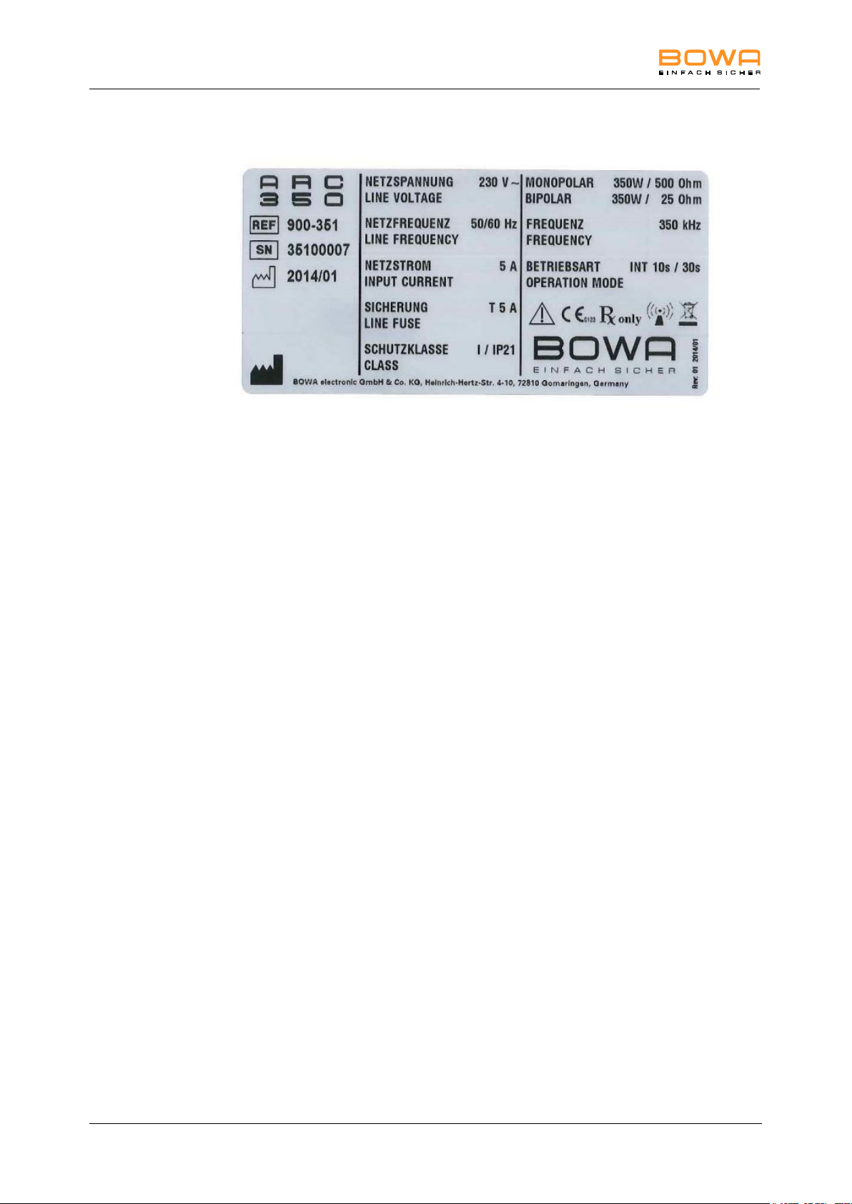
3.2.1. Rating label
Figure 3-1: ARC 350 rating label
(Here: ARC 350 incl. options LIGATION and Bipolar Resektion, ARC
350 with option LIGATION bipolar output power changes to 200W,
ARC 350 basic version provides a bipolar output power of 120W.)
3.3. Scope of delivery
You'll find detailed information on the scope of delivery in the current catalogues.
3.4. Components required for operation
Power cable
Foot switch
Neutral electrode for monopolar applications
Connection cable for neutral electrode or instrument
Instrument (monopolar or bipolar)
3.5. Operating conditions
Temperature: +10 °C to +40 °C
Relative humidity: 30 to 75%, non-condensing
Atmospheric pressure: 700 to 1060 hPa
Operating altitude (max.) 4000 m above sea level
22 Operating Manual ARC 350 900-351_IFU_V2.0.0_20221-S0-20150520-EN
Page 23
4 Prearrangement
NOTE
Electromagnetic fields are generated during normal use of the HF
device. This can adversely affect other devices.
Ensure that no electronic devices are placed in the vicinity of the
HF device.
WARNING
Shock hazard
Always connect the HF device to a grounded power distribution
system in order to prevent electric shock.
DANGER
Risk of burns to patients due to excessive leakage current
Locate the HF device outside the immediate vicinity of the patient,
see section Ambient conditions, page 11.
HF devices may be used only in rooms used for medical purposes that
meet the requirements of DIN VDE 0100-710.
If the HF device was previously stored or transported at temperatures
below +10 °C or a relative humidity above 75%, non-condensing, it will
take approximately three hours to adjust to room temperature.
4. Prearrangement
4.1. Setting up the HF device
1. Observe the specified operating conditions (see Section Operating conditions,
page 22.
2. Place the HF device on one of the following platforms:
a table;
an equipment trolley;
a console suspended from a ceiling support or wall-mounted
brackets.
3. Place the HF device a sufficient distance away from other electronic
equipment, see Section EMC, page 120.
4. Position the HF device with the front of the device facing the patient and
surgeon.
5. Do not place any other device on the HF device.
900-351_IFU_V2.0.0_20221-S0-20150520-EN Operating Manual ARC 350 23
Page 24

4 Prearrangement
Do not use the HF device if the display components are not working. See
Section faults Detecting and correcting faults, page 63 for
troubleshooting instructions.
6. Do not place any other objects on or above the HF device.
7. Place the HF device on top of ARC PLUS only, do not place it on other
devices.
8. Connect the power cord.
4.2. Switching on the HF device
1. Switch the HF device on using the on/off switch.
The HF unit performs a self-testing: All user interface components light up.
2. Check all controls and indicators for proper operation:
Power switch
Touchscreen
Monopolar socket connectors
Bipolar socket connectors
Activation indication for monopolar and bipolar sockets
The main screen appears, and the HF device is ready for use.
The parameters of the most recently selected program appear on the display.
4.3. Connecting instruments
Before connecting instruments, ensure that the following conditions are met:
Combinations of accessories not mentioned in the operating
manual may be used only if they are explicitly designed for the
intended use. Always observe performance characteristics and
safety requirements.
The insulation of the accessories (e.g. HF cables and instruments)
must be sufficient for the maximum peak output voltage (see IEC
60601-2-2 and IEC 60601-2-18).
Do not use accessories with defective insulation.
24 Operating Manual ARC 350 900-351_IFU_V2.0.0_20221-S0-20150520-EN
Page 25

4 Prearrangement
One double-pedal foot switch and one single pedal foot switch can be
connected. Foot switches without an orange changeover switch cannot
be used.
Only foot switch and fibre optics may be connected to the rear panel
during operation.
Item no.
Designation
901-011
Single-pedal foot switch with switch
901-031
Double-pedal foot switch with switch
901-032
Double-pedal foot switch with switch and clip
4.3.1. Instruments for monopolar use
1. Plug the neutral electrode cable into the socket for the neutral electrode and
choose the corresponding neutral electrode type, see chapter Selecting the
neutral electrode, page 35.
The socket illumination goes dark.
The neutral electrode button changes from grey to the measurement colour
(green, yellow or red).
2. Connect the electrode handle to one of the two monopolar socket connectors.
– or –
In the case of an accessory without a finger button, connect a footswitch to the
socket connector. Connect the Bovie connector of the monopolar cable to the
socket connector.
– or –
Connect the monopolar cable for endoscopy to one of the two monopolar
socket connectors for monopolar instruments.
4.3.2. Instruments for bipolar applications
1. Connect the bipolar cable to the instrument (e.g. forceps).
2. Connect the bipolar cable to one of the two bipolar socket connectors.
3. For bipolar use without AUTOSTART, connect a footswitch to the socket
connector.
– or –
Use the AUTOSTART mode for the appropriate socket connector.
Once the instrument is connected, the application starts after the configured
delay time.
4.3.3. Connecting a foot switch
In addition to the manual switch, a foot switch can be used to activate various
operating modes.
Connect the desired foot switch only during operation to one of the two socket
connectors for foot switches.
The HF device automatically detects the connected foot switch and indicates
this on the front panel display, including the selected socket connector.
The following foot switch systems can be connected to the HF device:
900-351_IFU_V2.0.0_20221-S0-20150520-EN Operating Manual ARC 350 25
Page 26

4 Prearrangement
The accessories must be designed for the specified maximum voltage.
The neutral electrode used for this test may not later be used for an
operation.
4.4. Functional test
4.4.1. Auto test function
The HF device automatically performs cyclic testing during operation. If any faults
occur, see Section Detecting and correcting faults, page 63.
4.4.2. Functional testing
Perform the following functional test before putting the device into service:
1. Connect the neutral electrode and attach it securely to the patient’s arm.
The EASY neutral electrode indicator changes to green.
2. Remove the neutral electrode.
The indicator changes to red, acoustic signals sound.
3. Connect a monopolar HF handle to a monopolar socket connector if there is a
green EASY indicator and use the manual switch and footswitch to individually
activate "Cut" and "Coag".
4. Check the settings on the display.
5. Now change to the bipolar output and connect bipolar forceps.
6. Select a mode with AUTOSTART, grasp moist gauze with the forceps, and
check the display.
7. Now change to a mode without AUTOSTART and use the footswitch to
activate the bipolar output. Check the settings and indicators in the bipolar
section.
26 Operating Manual ARC 350 900-351_IFU_V2.0.0_20221-S0-20150520-EN
Page 27
4 Prearrangement
The HF device can be switched off at any time by using on/off switch 27
as an emergency stop switch.
Always use the largest possible electrode when attaching a neutral
electrode.
BOWA recommends using split neutral electrodes, since only this type of
electrode allows the HF device to detect detachment of the neutral
electrode if this occurs.
4.4.3. Actions in case of problems
Proceed as follows in case of functional problems:
1. Immediately disconnect the patient from the HF device.
2. Inspect the HF device and perform a functional test.
3. Report incidents and near-accidents to the German Federal Institute for
Medications and Medical Products in accordance with Section 3 of the
German Ordinance on the Installation, Operation and Use of Medical Products
(MPBetreibV). Observe the provisions of the in-house reporting system in this
regard.
4. Consult the Technical Service department, see Section Technical service,
page 73.
4.5. Neutral electrode monitoring
4.5.1. General information
Monitoring of the neutral electrode minimizes the risk of burns at the site where the
neutral electrode is attached.
Two types of neutral electrodes can be monitored:
Split electrodes for infants (for use with reduced power)
Split neutral electrodes
The type of neutral electrode and its contact quality are selected and/or shown in
Neutral Electrode Modes menu.
Faults related to the neutral electrode and possible remedies are shown on the
display, see Section Detecting and correcting faults, page 63.
900-351_IFU_V2.0.0_20221-S0-20150520-EN Operating Manual ARC 350 27
Page 28

4 Prearrangement
The maximum output power of monopolar current types is reduced to
50 W when a children’s electrode is selected.
NOTE
Risk of incorrect application of the neutral electrode
Ensure compliance with the specifications for correct attachment of
the neutral electrode with regard to size, adhesive properties and
full-surface contact of the complete electrode.
4.5.2. EASY neutral electrode monitoring (EASY monitoring)
The EASY monitoring function measures changes in the resistance between the
patient and the high-frequency surgery device before and during HF activation. If
necessary, it generates visual and audible alarms to request staff intervention. This
requires using a split neutral electrode with appropriate contact areas and suitable
contact resistance, attached to the patient according to the manufacturer’s
instructions. The EASY system does not monitor the currents through the
individual contact surfaces of the split neutral electrode.
For the programs "Resection" and "Moderate Coagulation" a BOWA electrode with
a surface area of at least 90 cm² must be used.
If an error message is generated, the display changes from green via yellow to red,
depending on the type of fault.
28 Operating Manual ARC 350 900-351_IFU_V2.0.0_20221-S0-20150520-EN
Page 29
5 Operation
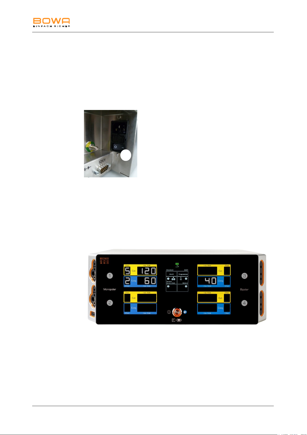
27
5. Operation
5.1. Connecting power
The line voltage must match the voltage specified on the rating label.
Connect the power cord to the generator and plug the cord into a grounded AC
power outlet.
Use the power switch 27 on the rear side of the unit to switch on the device.
Use the on/off switch on the front panel to switch on the device.
The device performs a functional test.
The activation indicators illuminate.
Full functionality of the loudspeaker is indicated by the start melody.
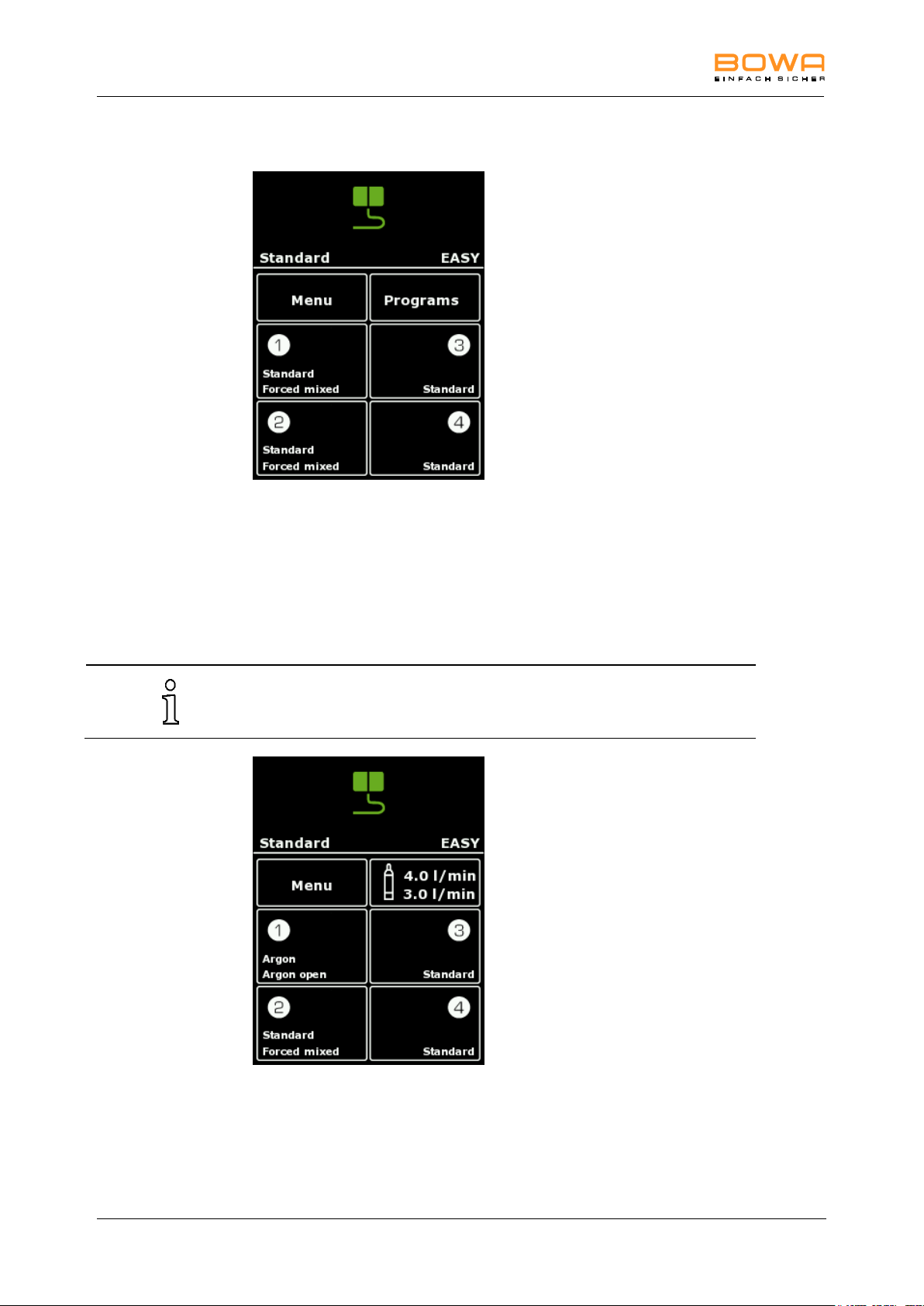
5.2. Program overview
Figure 5-1: Program overview
In the middle of the screen is the display to control the menu.
The activation indications and buttons to set the maximum output power and the
effect are allocated next to the corresponding sockets.
The effect of electrosurgical cutting or coagulation can be set using the button
"Effect".
The "max. Watt" button is used to set the maximum output power.
900-351_IFU_V2.0.0_20221-S0-20150520-EN Operating Manual ARC 350 29
Page 30
5 Operation
In this case the program can be selected using Menu "Select program".
5.2.1. Display
Figure 5-2: Standard display
In the upper segment of the display the "EASY" button is allocated.
In the lower part of the display the program name, the neutral electrode type, as
well as the buttons "Menu", "Programs" and settings of the current type and pedal
for the four sockets are allocated.
In combination with ARC PLUS and the selection of Argon modes, instead of the
button "Programs" the "Argon" menu is shown.
Figure 5-3: Argon display
30 Operating Manual ARC 350 900-351_IFU_V2.0.0_20221-S0-20150520-EN
Page 31
5 Operation
All selection windows are closed after 30 seconds without assumption of
the modification.
If selection screens are present, buttons outside the screen stay active
and when being touched close the present screen without modification.
In addition, activations not possible in this case.
A change to the currently loaded program, e.g. by adjusting the power
level, is indicated by a red illuminated program name.
5.3. Activating and deactivating connectors
To activate a deactivated socket connector, plug a connecting cable into the
connector.
– or –
Tap the activation indication of the associated socket.
The selection field and the activation indication lights up.
When detaching the instrument, the activation indicator extinguishes.
To hide sockets tap the activation display of the associated socket.
The parameters for maximum power and effect are grayed out.
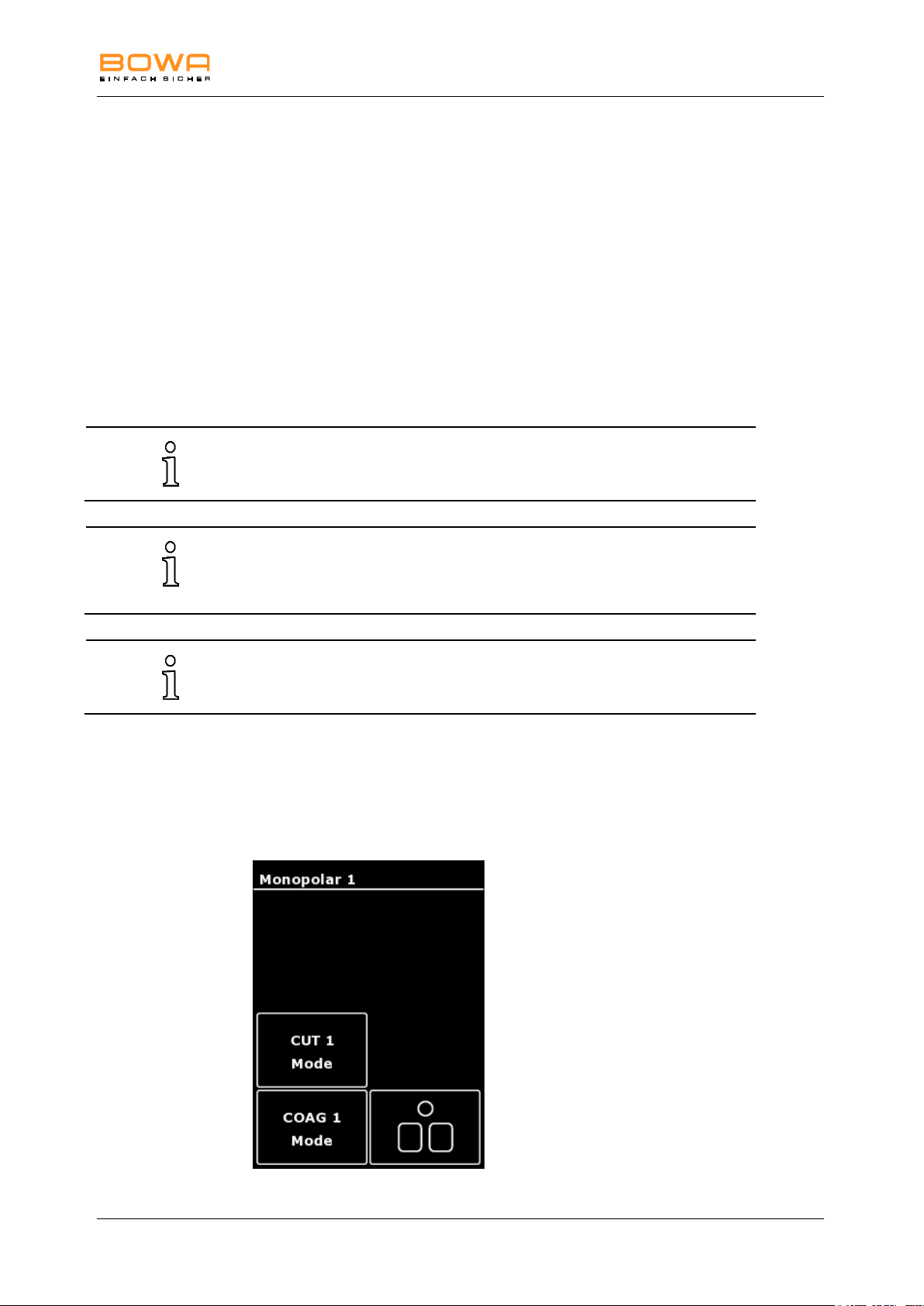
5.4. Configuring output currents
5.4.1. Selecting the mode
1. To select the type of current, select the setting of the respective socket.
A menu appears to select the program, the foot switch assignment as well as
the modes for cutting or coagulation.
Figure 5-4: Menu Monopolar 1
900-351_IFU_V2.0.0_20221-S0-20150520-EN Operating Manual ARC 350 31
Page 32
5 Operation
If a mode is changed within a socket, the set parameters e.g. effect and
max. Watt, remain the same for the respective mode. However, if, for
example, the factory default setting of a mode is adapted and
subsequently changed to a different mode and then back again, the user
changes are not undone.
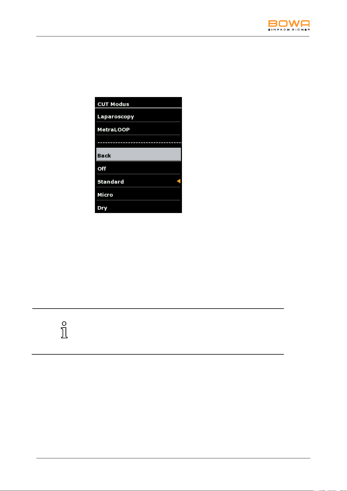
2. Choose the menu of the required current type using the "Mode" button.
A selection screen appears for the available modes.
The active mode is indicated with an orange arrow.
Figure 5-5: Modes monopolar cutting
3. Select the required mode using the arrow keys.
- orDeactivate the mode by selecting "Off".
4. Confirm the selection with the "OK" button.
The main screen is displayed.
- orTo return to the main screen without changing the selection, select "Back" or
tap any button outside the selection menu.
32 Operating Manual ARC 350 900-351_IFU_V2.0.0_20221-S0-20150520-EN
Page 33
5 Operation
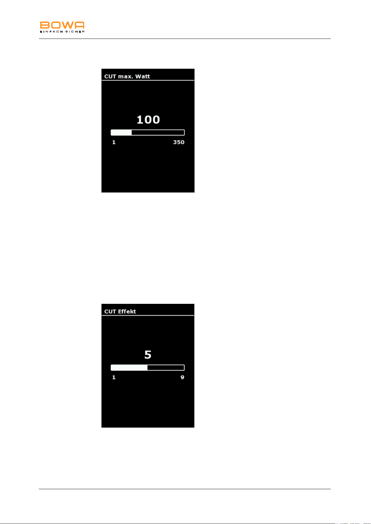
5.4.2. Specifying power limits
Figure 5-6: Power limit monopolar cutting
1. To select the maximum power tap the parameters below the display
“max. Watt”.
2. Use the "+" and "-" buttons to adjust the power level.
3. Confirm your selection by pressing the "OK" button.
- or To return to the main screen without changing the selection, tap any button
outside the selection menu.
5.4.3. Selecting the effect
Figure 5-7: Effect monopolar cutting
1. To select the maximum power tap the parameters below the display "Effect".
2. Use the "+" and "-" buttons to adjust the effect.
900-351_IFU_V2.0.0_20221-S0-20150520-EN Operating Manual ARC 350 33
Page 34
5 Operation
Handles and instruments with manual switches can be activated without
a configuration setting.
3. Confirm your selection by pressing the "OK" button.
- or To return to the main screen without changing the selection, tap any button
outside the selection menu.
5.4.4. Assigning the foot pedal
A single-pedal foot switch and/or double-pedal foot switch, each with a changeover
switch, can be connected,
The changeover switch enables switching between pedal levels.
1. Select the foot switch menu using the selection of the respective socket
A menu appears for selecting the program, foot switch assignment as well as
modes for cutting or coagulation.
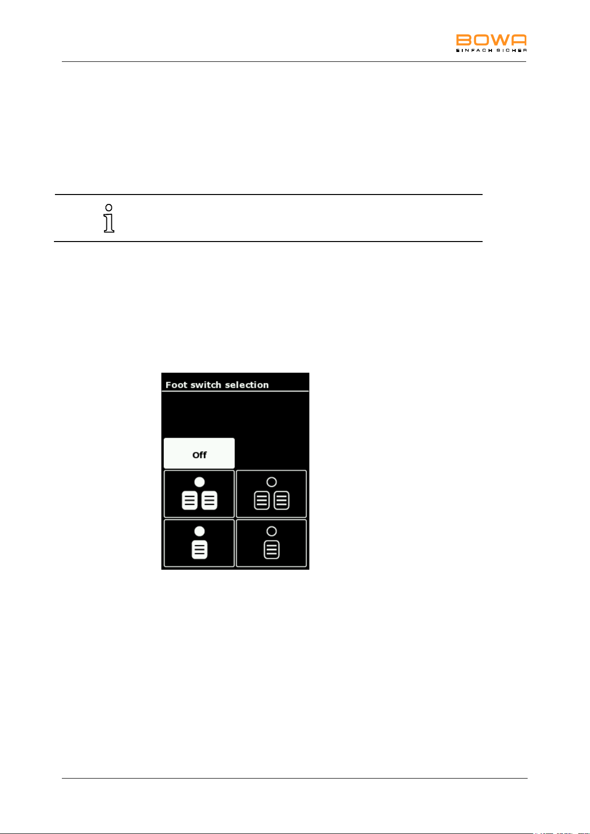
2. Enter the selection menu of the footswitch using the “Pedal” button on.
Figure 5-8: Foot switch selection
3. Select the required foot switch by pressing the corresponding button.
For example, you could select the active pedal level for cutting, and
coagulation for the top, left-hand socket.
- orDeactivate the footswitch using the “Off“ button.
4. Confirm the selection by pressing the "OK" button.
- orTo return to the main screen without changing the selection, tap any button
outside the selection menu.
34 Operating Manual ARC 350 900-351_IFU_V2.0.0_20221-S0-20150520-EN
Page 35
5 Operation
If two footswitches are connected, either a single-pedal footswitch or a
double-pedal footswitch can be selected for coagulation.
Figure 5-9: Foot switch changeover
5. Pedal levels can be changed using the foot switches. Press the orange button
to change the socket.
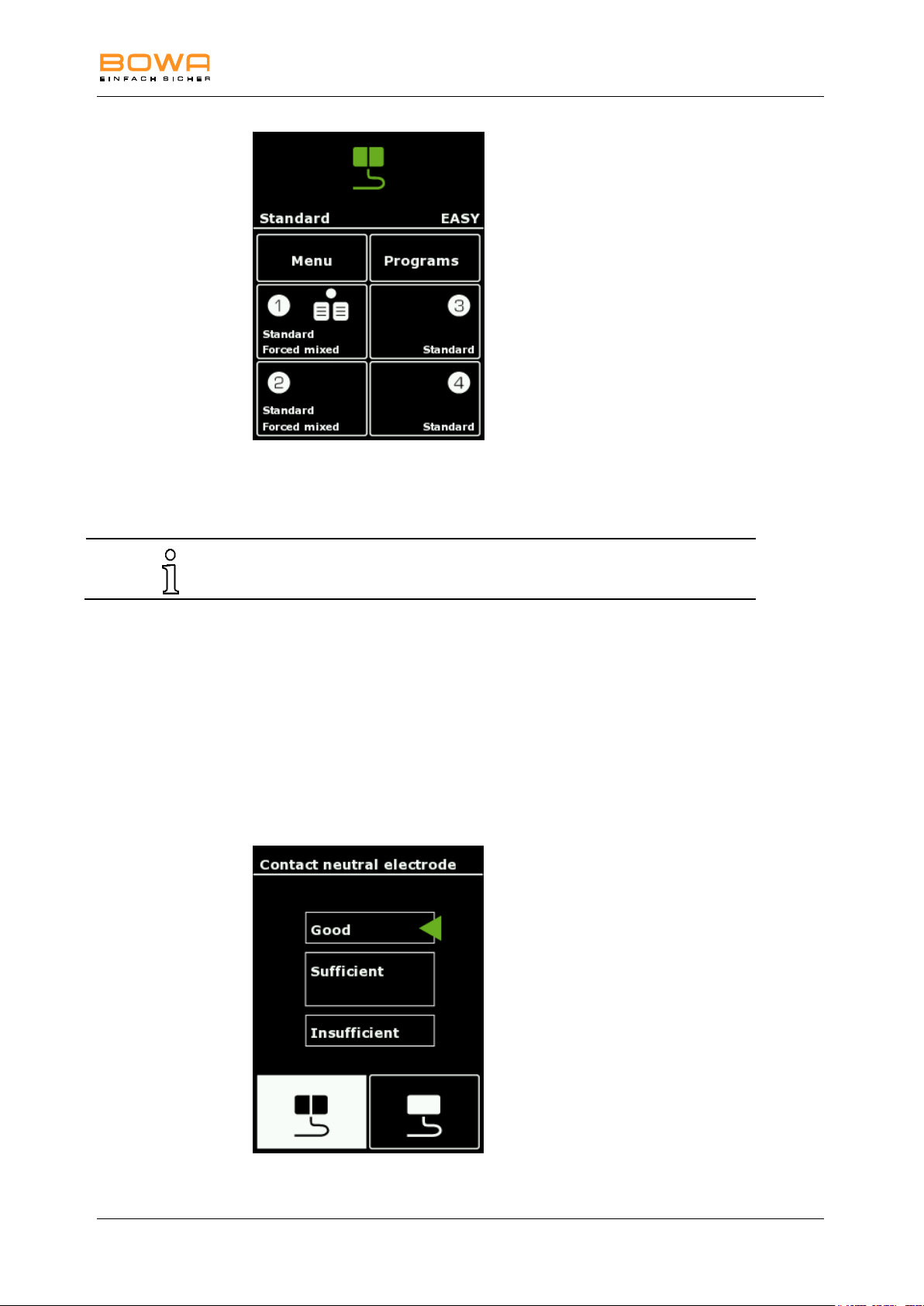
5.4.5. Selecting the neutral electrode
1. Press the "EASY" button in the upper segment of the display to select the
neutral electrode.
- or Alternatively, use "Menu" "neutral electrode" to select the neutral electrode.
The neutral electrode menu with a display of contact quality as well as
selection of the neutral electrode types is shown.
The selected neutral electrode type is displayed in white.
Figure 5-10: Neutral electrode menu
900-351_IFU_V2.0.0_20221-S0-20150520-EN Operating Manual ARC 350 35
Page 36
5 Operation
The maximum power output of monopolar current types is reduced to
50 W when a children’s electrode is selected.
When using the "EASY" and "BABY" mode, no non-split electrodes are
accepted. Using the "MONO" mode, no split electrodes are accepted.
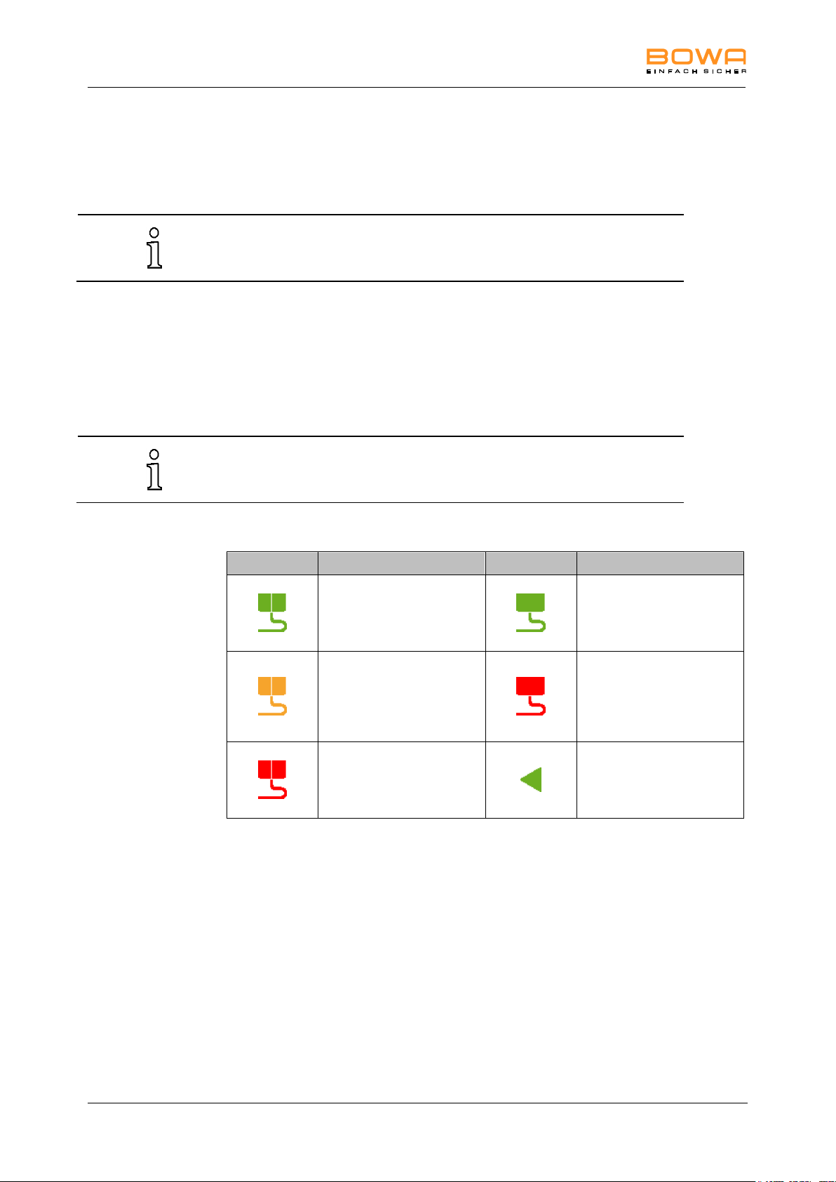
Icon / Button
Description
Icon / Button
Description
Split neutral electrode
contact quality OK
Non-split neutral
electrode
contact quality OK
Split neutral electrode
contact quality not
optimum
Not Detected non-split
neutral electrode
or connected
or contact quality
insufficient
Split neutral electrode
not connected
or contact quality
insufficient
Display the contact
quality.
2. Select the type of connected electrode by selecting the icon for split or nonsplit neutral electrodes.
3. In the selection of split neutral electrodes there is also a reduced power mode
for children electrodes available
4. Confirm your selection by pressing the "OK" button.
- or To return to the main screen without changing the selection, tap any button
outside the selection menu.
The selected type of neutral electrode in connection with a colour-indicator for
the contact quality is shown in the status bar.
According to the contact quality, several icons are shown for neutral electrodes:
36 Operating Manual ARC 350 900-351_IFU_V2.0.0_20221-S0-20150520-EN
Page 37
5 Operation
This function is available if the device has an option Argon / GastroCut,
Bipolar Resection or LIGATION.
5.4.6. Plug’n Cut COMFORT
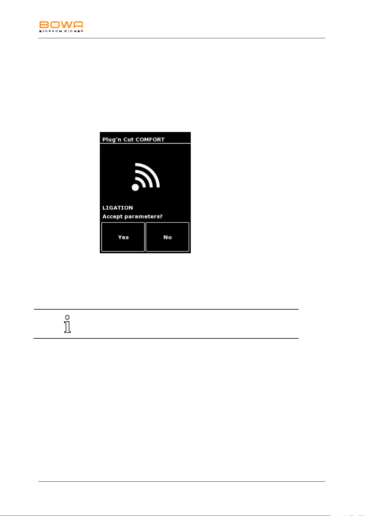
The automatic instrument identification Plug’n Cut COMFORT recognises the
connected BOWA COMFORT instrument and selects the default parameters
automatically.
1. Insert the COMFORT instrument into a socket of ARC 350.
The accepted parameters are displayed
Figure 5-11: Plug’n Cut COMFORT
2. Confirm the selection of preferred parameters with "Yes".
- orReturn to the main screen without accepting the preferred parameters with "No".
900-351_IFU_V2.0.0_20221-S0-20150520-EN Operating Manual ARC 350 37
Page 38
5 Operation
Monopolar Cutting
Monopolar Coagulation
Standard
Moderate
Micro
Forced coag
Dry
Forced mixed
MetraLOOP
Forced cutting
Resection
Spray
Laparoscopy
Laparoscopy
Argon *
Argon open*
GastroLOOP 1 G
Argon flexible *G
GastroLOOP 2 G
Argon flex. pulse *G
GastroLOOP 3 G
Gastro Coag G
GastroKNIFE 1 G
Resection
GastroKNIFE 2 G
Mammary
GastroKNIFE 3 G
Thorax
SimCoag
* These modes can only be used in connection with the argon coagulation
unit ARC PLUS (900-001).
G
These modes are available with the option Argon / GastroCut (900-391).
5.5. Mode overview
An overview of the programs that can be executed with the HF device is shown
below.
5.5.1. Monopolar modes
38 Operating Manual ARC 350 900-351_IFU_V2.0.0_20221-S0-20150520-EN
Page 39
5 Operation
Bipolar Cutting
Bipolar Coagulation
Bipolar Cutting
Standard
Bipolar Resection R
Standard AUTO
Bipolar Scissors
Micro
Forced
LIGATION L
TissueSeal PLUS L
Bipolar Scissors
Laparoscopy
Bipolar Resection R
R These modes are available with the option Bipolar Resection (900-395).
L
These modes are available with the option LIGATION (900-396).
The information and data regarding settings, application points,
application duration and instrument use are based on clinical practice.
However, these are only basic guidelines which must be tested for
suitability by the operator. Depending on individual conditions, it may be
necessary to deviate from the provided data.
Medical practice is continuously evolving as a result of R&D and clinical
experience. This may also make deviations from the provided data
necessary.
5.5.2. Bipolar modes
900-351_IFU_V2.0.0_20221-S0-20150520-EN Operating Manual ARC 350 39
Page 40

5 Operation
5.6. Monopolar cutting modes
5.6.1. Standard
In this mode a high-performance HF current with a low crest factor is used for
cutting biological tissue. ARC CONTROL quickly adjusts the power output to the
minimum required level in response to variations in tissue type and changes in the
cutting area or speed.
Application areas
Cutting tissue with low electrical resistance, such as muscle tissue or vascular
tissue.
Cutting or preparing fine structures
Suitable instruments
Needle electrodes
Knife electrodes
Spatula electrodes
Sling electrodes
5.6.2. Micro
This mode is used for electrosurgical cutting using micro-electrodes. It enables
extremely fine control of the power level and precise work.
Application areas
Paediatric surgery, neurosurgery, plastic surgery
Suitable instruments
Micro needle electrodes
5.6.3. Dry
This mode is used for monopolar dry cutting. A large, controlled arc is generated,
which allows significantly deeper coagulation to be obtained.
Application areas
Cardiac surgery and blood coagulation in retracting blood vessels in the sternum
region.
Suitable instruments
Knife electrodes
40 Operating Manual ARC 350 900-351_IFU_V2.0.0_20221-S0-20150520-EN
Page 41

5 Operation
Use non-conductive irrigation fluids.
5.6.4. Argon
This mode is used to perform open surgical interventions in combination with the
ARC PLUS companion device for argon-assisted cutting. With suitable instruments
connected, argon-assisted cutting can be performed using rigid electrodes.
Application areas
Visceral surgery
Suitable instruments
Rigid argon electrodes
Argon handles
5.6.5. Resection
This mode is used in gynaecology and urology. ARC control generates the cutting
effect with simultaneously minimized output power. ARC control facilitates direct
cutting and prevents electrode adhesion.
Application areas
Hysteroscopy, transurethral prostate resection (TUR-P), surgical treatment of
bladder tumors (TUR-B), vaporization of prostate tissue (TUR-VAP).
Suitable instruments
Resectoscope (monopolar)
Resection snare
Rollerblade electrode
900-351_IFU_V2.0.0_20221-S0-20150520-EN Operating Manual ARC 350 41
Page 42

5 Operation
This function is available if the device has the options argon / GastroCut
(900-391).
5.6.6. MetraLOOP
This mode is used in gynaecology for laparoscopic hysterectomy. Removal of the
uterus can be achieved by applying monopolar cutting current and pulling on the
snare at the same time.
Application areas
Gynaecology; laparoscopic hysterectomy
Suitable instruments
Gynaecological laparoscopic snares
5.6.7. Laparoscopy
This mode is used in laparoscopy and arthroscopy for monopolar cutting.
Application areas
Laparoscopy, arthroscopy
Suitable instruments
Arthroscopy electrodes
Laparoscopy electrodes
5.6.8. GastroLOOP 1 (optional)
This mode is used in gastroenterology. Polypectomy snares are used for cutting
and coagulation. ARC control generates the cutting effect with simultaneously
minimized output power. This mode consists of a series of cutting current pulses
followed by a coagulation phase. With a relatively slow pulse rate of 1 cutting pulse
per second, this mode is suitable for especially cautious work.
Application areas
Polyp removal using polypectomy snares and flexible endoscopy
Suitable instruments
Polypectomy snares
42 Operating Manual ARC 350 900-351_IFU_V2.0.0_20221-S0-20150520-EN
Page 43

5 Operation
This function is available if the device has the options argon / GastroCut
(900-391).
This function is available if the device has the options argon / GastroCut
(900-391).
5.6.9. GastroLOOP 2 (optional)
This mode is used in gastroenterology. Polypectomy snares are used for cutting
and coagulation. ARC control generates the cutting effect with simultaneously
minimized output power. This mode consists of a series of cutting current pulses
followed by a coagulation phase. With an accelerated pulse rate of 1.8 cutting
pulses per second, this mode is suitable for experienced users.
Application areas
Polyp removal using polypectomy snares and flexible endoscopy, with accelerated
pulse rate for experienced users.
Suitable instruments
Polypectomy snares
5.6.10. GastroLOOP 3 (optional)
This mode is used in gastroenterology. Polypectomy snares are used for cutting
and coagulation. ARC control generates the cutting effect with simultaneously
minimized output power. This mode consists of a series of cutting current pulses
followed by a coagulation phase. With an accelerated fast pulse rate of 3.2 - 5
cutting pulses per second, this mode is suitable for advanced users.
Application areas
Polyp removal using polypectomy snares and flexible endoscopy, with accelerated
fast pulse rate for advanced users.
Suitable instruments
Polypectomy snares
900-351_IFU_V2.0.0_20221-S0-20150520-EN Operating Manual ARC 350 43
Page 44

5 Operation
This function is available if the device has the options argon / GastroCut
(900-391).
This function is available if the device has the options argon / GastroCut
(900-391).
5.6.11. GastroKNIFE 1 (optional)
This mode is used in gastroenterology. Instruments for papillotomy and
endoscopic resections are used for cutting and coagulation. ARC control
generates the cutting effect with simultaneously minimized output power. This
mode consists of a pulse sequence of cutting current and coagulation phase. With
a relatively slow pulse rate of 1.3 cutting pulse per second, this mode is suitable for
especially cautious work.
Application areas
Papilla incision using a papillotome and flexible endoscopy, resection with needle
knives; slow pulse rate for cautious work.
Suitable instruments
Papillotome
Needle knives
5.6.12. GastroKNIFE 2 (optional)
This mode is used in gastroenterology. Instruments for papillotomy and
endoscopic resections are used for cutting and coagulation. ARC control
generates the cutting effect with simultaneously minimized output power. This
mode consists of a pulse sequence of cutting current and coagulation phase. With
an accelerated pulse rate of 1.7 cutting pulses per second, this mode is suitable for
experienced users.
Application areas
Papilla incision using a papillotome and flexible endoscopy, resection with needle
knives; accelerated pulse rate for experienced users.
Suitable instruments
Papillotomes
Needle knives
44 Operating Manual ARC 350 900-351_IFU_V2.0.0_20221-S0-20150520-EN
Page 45

5 Operation
This function is available if the device has the options argon / GastroCut
(900-391).
5.6.13. GastroKNIFE 3 (optional)
This mode is used in gastroenterology. Instruments for papillotomy and
endoscopic resections are used for cutting and coagulation. ARC control
generates the cutting effect with simultaneously minimized output power. This
mode consists of a pulse sequence of cutting current and coagulation phase. With
an accelerated fast pulse rate of 2.2 cutting pulses per second, this mode is
suitable for advanced users.
Application areas
Papilla incision using a papillotome and flexible endoscopy, resection with needle
knives; accelerated fast pulse rate for advanced users.
Suitable instruments
Papillotome
Needle knives
5.7. Monopolar coagulation modes
5.7.1. Moderate
This mode is used with contact coagulation to stop hemorrhagic oozing, for
hemostasis of relatively large tissue areas, and for small-area coagulation. Tissue
carbonization is prevented and electrode adhesion to the tissue is strongly
reduced. Greater coagulation depth is achieved in this mode than in other
coagulation modes. The degree of surface scabbing can be controlled by adjusting
the "Effect" setting in the range of 1 to 3.
Application areas
Coagulation with relatively high penetration depth; low electrode adhesion to tissue
Suitable instruments
Electrodes with large contact areas, such as ball electrodes
900-351_IFU_V2.0.0_20221-S0-20150520-EN Operating Manual ARC 350 45
Page 46

5 Operation
5.7.2. Forced coag
This mode is used for contact coagulation with low tissue penetration, preferably
using fine electrodes and electrodes with small contact areas. It achieves a high
degree of coagulation with low cutting tendency.
Application areas
Fast coagulation with small penetration depth
Suitable instruments
Ball electrodes
Knife electrodes
Spatula electrodes
5.7.3. Forced mixed
This mode is used for contact coagulation with low tissue penetration, preferably
using fine electrodes and electrodes with small contact areas. It achieves a high
degree of coagulation with moderate cutting tendency.
Application areas
Fast coagulation with small penetration depth and moderate cutting tendency
Suitable instruments
Knife electrodes
Spatula electrodes
Insulated monopolar forceps
5.7.4. Forced cutting
This mode is used for contact coagulation with low tissue penetration, preferably
using fine electrodes and electrodes with small contact areas. It achieves good
hemostasis with very good cutting tendency.
Application areas
Fast coagulation with small penetration depth and very good cutting tendency
Suitable instruments
Knife electrodes
Spatula electrodes
Needle electrodes
46 Operating Manual ARC 350 900-351_IFU_V2.0.0_20221-S0-20150520-EN
Page 47

5 Operation
5.7.5. Spray
This mode is used with non-contact surface coagulation using an arc, for
hemostasis in parenchymal tissue, in poorly accessible crevices, and in
conjunction with argon coagulation.
Application areas
Promoting coagulation of diffuse bleeding
Suitable instruments
Ball electrodes
Knife electrodes
Spatula electrodes
Needle electrodes
5.7.6. Argon open
This mode is used for open surgical interventions in conjunction with the ARC
PLUS accessory device for argon-assisted electrocoagulation.
This is the current type Spray.
With suitable instruments connected, argon-assisted coagulation can be performed
using rigid electrodes.
Application areas
Visceral surgery
Suitable instruments
Rigid argon electrodes
Argon handpiece
900-351_IFU_V2.0.0_20221-S0-20150520-EN Operating Manual ARC 350 47
Page 48

5 Operation
This function is available if the device has the options argon / GastroCut
(900-391).
This function is available if the device has the options argon / GastroCut
(900-391).
5.7.7. Argon flexible (optional)
This mode is used for argon-assisted electrosurgery in conjunction with the ARC
PLUS accessory device.
This is the current type Spray.
For argon-assisted coagulation, flexible probes are used in combination with
endoscopes.
Application areas
Gastroenterology, homogeneous surface coagulation
Suitable instruments
Flexible argon probes
5.7.8. Argon flex. pulse (optional)
This mode is used for argon-assisted electrosurgery in conjunction with the ARC
PLUS accessory device.
This is the current type Spray.
For argon-assisted coagulation, flexible probes are used in combination with
endoscopes.
The puls frequency changes with the effect setting. The higher the effect level, the
faster the pulse sequence.
Application areas
Gastroenterology, homogeneous surface coagulation
Suitable instruments
Flexible argon probes
48 Operating Manual ARC 350 900-351_IFU_V2.0.0_20221-S0-20150520-EN
Page 49

5 Operation
Use non-conductive irrigation fluids.
5.7.9. Resection
This mode is used for monopolar hemostasis in gynaecology and urology.
Application areas
Hysteroscopy, transurethral prostate resection (TUR-P), surgical treatment of
bladder tumors (TUR-B), vaporization of prostate tissue (TUR-VAP).
Suitable instruments
Resectoscope (monopolar)
Resection snare
Rollerblade electrode
5.7.10. Cardiac Mammary
This mode is used in mammary surgery and cardiac surgery. It produces forced
coagulation.
Application areas
Mammary surgery and cardiac surgery
Suitable instruments
Knife electrodes
5.7.10. Cardiac Thorax
This mode is used in thoracic surgery. It produces forced coagulation.
Application areas
Thoracic surgery
Suitable instruments
900-351_IFU_V2.0.0_20221-S0-20150520-EN Operating Manual ARC 350 49
Knife electrodes
Page 50

5 Operation
The output power setting applies to both output sockets, and the power
is distributed according to the tissue structure.
This function is available if the device has the options argon / GastroCut
(900-391).
5.7.11. SimCoag
This mode is used for simultaneous preparation. Two monopolar socket
connectors can be activated at the same time to enable the simultaneous use of
two manually switched instruments. Both handles can be switched on and off
independently.
The current type changes with the effect setting:
Effect 1: Forced cutting
Effect 2: Forced mixed
Effect 3: Spray
Application areas
Simultaneous coagulation and preparation, e.g. for cardiac or mammary surgery
Suitable instruments
Ball electrodes
Knife electrodes
Spatula electrodes
5.7.12. Gastro Coag (optional)
This mode is used in gastroenterology with contact coagulation for the coagulation
of small areas.
Application areas
After bleeding associated with polypectomy or papillotomy.
Suitable instruments
Polypectomy snares
Papillotome
5.7.13. Laparoscopy
This mode is used in laparoscopy and arthroscopy for monopolar coagulation.
Application areas
Laparoscopy, arthroscopy
Suitable instruments
Arthroscopy electrodes
Laparoscopy electrodes
50 Operating Manual ARC 350 900-351_IFU_V2.0.0_20221-S0-20150520-EN
Page 51

5 Operation
Make sure that NaCl is used as an irrigation medium.
Secure a continuous irrigation during the application.
Always use conductive lubricants to avoid damages of the urethra.
Avoid continuous activations.
This function is available if the device has the options Bipolar Resection
(900-395).
Optimum results are provided exclusively when using BOWA COMFORT
resection cables.
5.8. Bipolar cutting modes
5.8.1. Standard
This mode is used for cutting with bipolar laparoscopic instruments.
Application areas
Laparoscopic cutting
Suitable instruments
Laparoscopic instruments
5.8.2. Bipolar resection (optional)
This bipolar mode is used in gynaecology and urology for cutting under saline.
ARC control technology generates the cutting effect with simultaneously minimized
output power. ARC Control facilitates immediate cutting and prevents electrode
adhesion.
Application areas
Hysteroscopy, transurethral prostate resection (TUR-P), surgical treatment of
bladder tumors (TUR-B), vaporization of prostate tissue (TUR-VAP).
Suitable instruments
Resectoscope (bipolar)
Resection snare
Rollerblade electrode
900-351_IFU_V2.0.0_20221-S0-20150520-EN Operating Manual ARC 350 51
Page 52
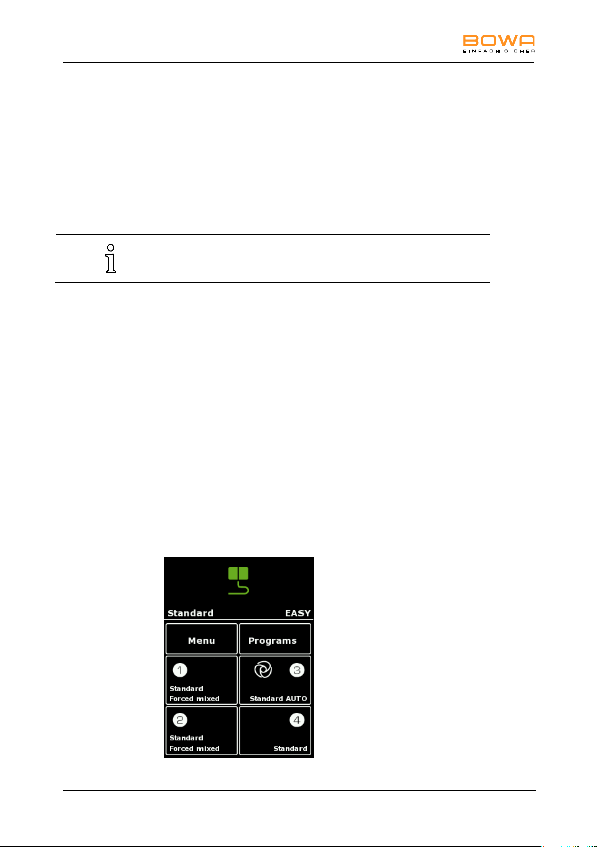
5 Operation
Bipolar scissors should only be operated with the current type bipolar
scissors cutting or bipolar scissors coagulation.
5.8.3. Bipolar scissors
This mode is used with bipolar scissors. It can be used for coagulation before or
during cutting, point coagulation, coagulation of cuts and surface coagulation.
Application areas
Preparation, coagulation and cutting of tissue
Suitable instruments
Bipolar scissors
5.9. Bipolar coagulation modes
5.9.1. Standard forceps
This mode is used for arcless contact coagulation with forceps.
Application areas
Bipolar coagulation
Suitable instruments
Bipolar forceps
5.9.2. Standard forceps AUTO
This mode is used for arcless contact coagulation with forceps. Activation starts
automatically on contact with tissue.
Figure 5-12: AUTOSTART at socket 3
52 Operating Manual ARC 350 900-351_IFU_V2.0.0_20221-S0-20150520-EN
Page 53

5 Operation
Setting the AUTOSTART mode can result in unintentional coagulations,
e.g. when bipolar forceps are used for gripping while the AUTOSTART
Mode is on.
The adjustable delay time can be set under MENU – SYSTEM SETTINGS –
AUTOSTART DELAY.
Application areas
Bipolar coagulation with AUTOSTART
Suitable instruments
Bipolar forceps
5.9.3. Micro forceps
This mode is used for arcless contact coagulation with micro forceps. It enables
extremely fine control of power output down to 0.1 W and precise work for tightly
restricted bipolar contact coagulation.
Application areas
Bipolar coagulation in paediatric surgery, neurosurgery, plastic surgery, etc.
Suitable instruments
Bipolar forceps
Micro forceps
5.9.4. Forceps forced
This mode is used for forced coagulation with forceps.
Application areas
Fast bipolar coagulation
Suitable instruments
Bipolar forceps
900-351_IFU_V2.0.0_20221-S0-20150520-EN Operating Manual ARC 350 53
Page 54

5 Operation
This function is available if the device has the option LIGATION
(900-396)
This function is available if the device has the option LIGATION
(900-396)
5.9.5. LIGATION (optional)
This mode is used for the permanent sealing of veins, arteries and tissue bundles.
Conventional instruments cannot be used in this mode. The output power is
preconfigured and automatically regulated.
Application areas
Vessel sealing open and laparoscopic
Suitable instruments
TissueSeal®
TissueSeal® PLUS
NightKNIFE®
LIGATOR®
5.9.6. TissueSeal PLUS (optional)
This mode is used for the permanent sealing of veins, arteries and tissue bundles
with TissueSeal PLUS® for open surgical applications. Conventional instruments
cannot be used in this mode. The output power is preconfigured and automatically
regulated.
Application areas
Vessel sealing in open surgery
Suitable instrument
TissueSeal PLUS®
54 Operating Manual ARC 350 900-351_IFU_V2.0.0_20221-S0-20150520-EN
Page 55

5 Operation
Bipolar scissors should only be operated with the current type bipolar
scissors cutting or bipolar scissors coagulation.
Use NaCl as irrigation fluid.
Make sure that the instrument has contact with the tissue while activating
bipolar coagulation to avoid an unintended heating of the irrigation fluid.
This function is available if the device has the option Bipolar Resection
(900-395)
5.9.7. Bipolar scissors
This mode is used with bipolar scissors. It can be used for coagulation before or
during cutting, point coagulation, coagulation of cuts and surface coagulation.
Application areas
Preparation, coagulation and cutting of tissue
Suitable instruments
Bipolar scissors
5.9.8. Laparoscopy
This mode is used for coagulation in combination with bipolar laparoscopic
instruments.
Application areas
Laparoscopic coagulation
Suitable instruments
Laparoscopic instruments
5.9.9. Bipolar resection (optional)
This mode is used for bipolar haemostasis in gynaecology and in urology for
cutting under saline.
Application areas
Hysteroscopy, transurethral prostate resection (TUR-P), surgical treatment of
bladder tumours (TUR-B), vaporization of prostate tissue (TUR-VAP)
Suitable instruments
Resectoscope
Resection snare
Rollerblade electrode
900-351_IFU_V2.0.0_20221-S0-20150520-EN Operating Manual ARC 350 55
Page 56
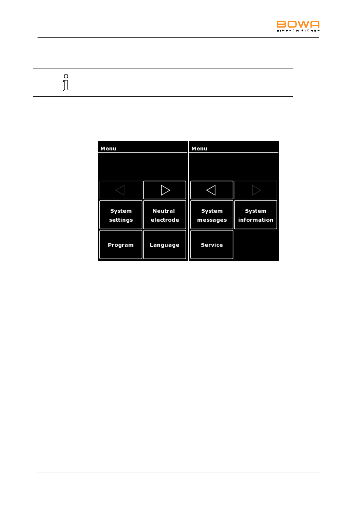
5 Operation
The menu dialogs specify the settings of basic parameters, such as the
user interface language and audio, display and memory options.
5.10. Menu dialogs
5.10.1. Overview
The following menu dialogs are available:
Figure 5-13: Menu dialogs
Selecting a dialog
Switch to the required function with the horizontal arrow keys, and press the
appropriate selection button to open the menu.
Exiting a dialog
Press the "OK" button to return to the main screen.
5.10.2. "System Settings" dialog
The "System" menu allows settings for brightness and volume of the alarm
activation and key tones, as well as autostart delay.
56 Operating Manual ARC 350 900-351_IFU_V2.0.0_20221-S0-20150520-EN
Page 57
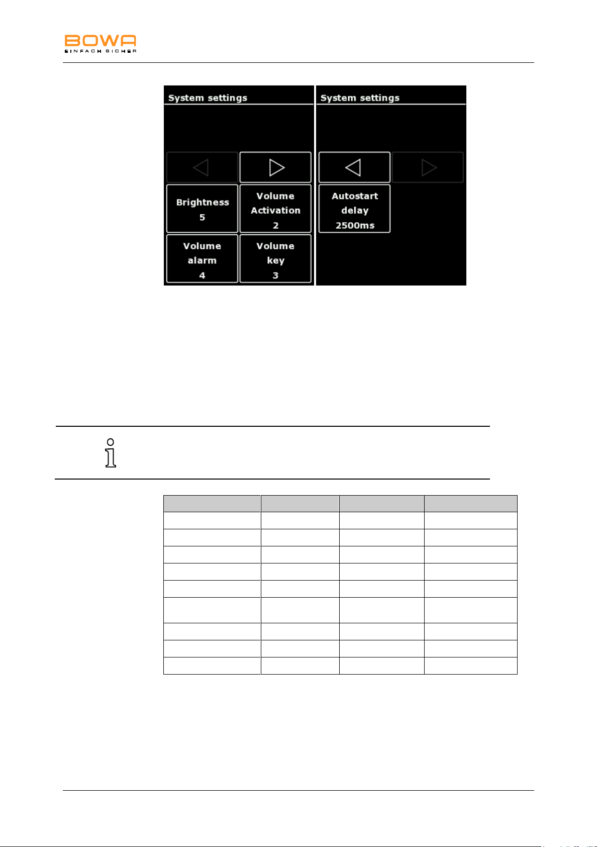
5 Operation
The volume of the activation signal should be increased as necessary for
use in relativey noisy surrouondings. The alarm tones have a minimum
volume and limited changeability.
Mode
Category
Frequency (Hz)
Signal type
Monopolar Cut
Activation tones
635
Continuous sound
Monopolar Coag
Activation tones
475
Continuous sound
Bipolar Cut
Activation tones
565
Continuous sound
Bipolar Coag
Activation tones
505
Continuous sound
Sim Coag
Activation tones
755
Continuous sound
GastroCut /LIGATION
end
Alarm tones
-
alternating sound
Error
Alarm tones
-
Signal tone
Warning
Alarm tones
-
Signal tone
Note
Alarm tones
-
Signal tone
Figure 5-14: “System settings” dialog
1. To change the system settings, tap the desired parameter.
2. Change the setting in single steps with the keys "+" and "-"
3. Confirm the selection with the "OK" button.
- orTo return to the main screen without changing the selection, tap any button
outside the selection menu.
5.10.3. “Neutral electrode“ dialog
In the "Neutral electrode" menu the connected neutral electrode type is selected
and the contact quality is displayed, see chapter Selecting the neutral electrode,
page 35.
900-351_IFU_V2.0.0_20221-S0-20150520-EN Operating Manual ARC 350 57
Page 58
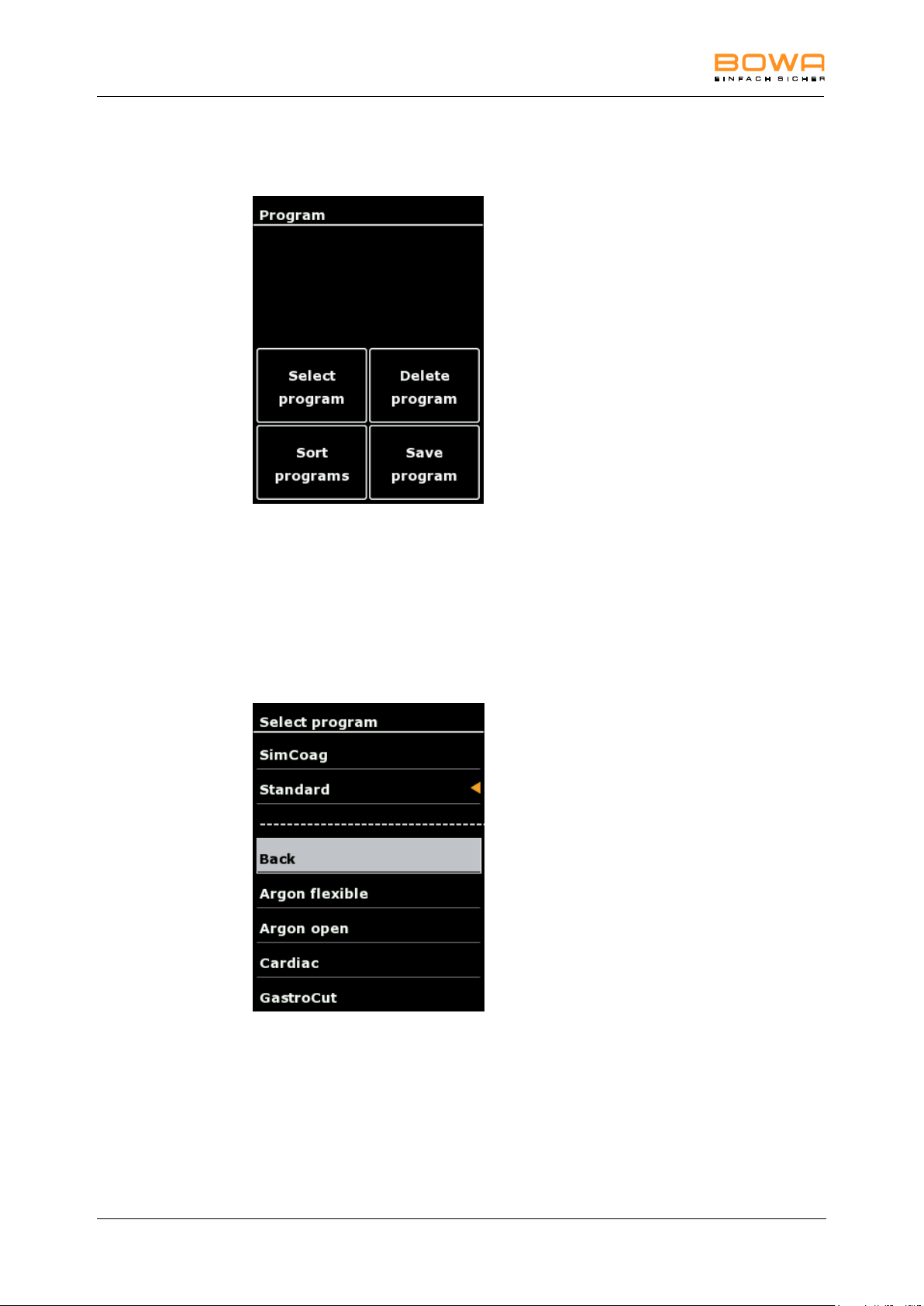
5 Operation
5.10.4. “Program“ dialog
In the “program“ dialog it is possible to choose, delete, sort and save programs.
Figure 5-15: Menu "Program"
Select program
1. Tap "Select program" to enter the program list.
Fast settings of this menu are possible by tapping the socket menu on the
main screen, see chapter Selecting the mode, page 31.
A list of saved programs appears.
The currently loaded program is visualized by the orange arrow.
Figure 5-16: "Select program" dialog
2. Select the desired program by using the arrow keys.
3. Confirm the selection with the “OK“ button
The main screen is displayed
- orTo return to the main screen without changing the selection, select "Back" or
tap any button outside the selection menu.
58 Operating Manual ARC 350 900-351_IFU_V2.0.0_20221-S0-20150520-EN
Page 59
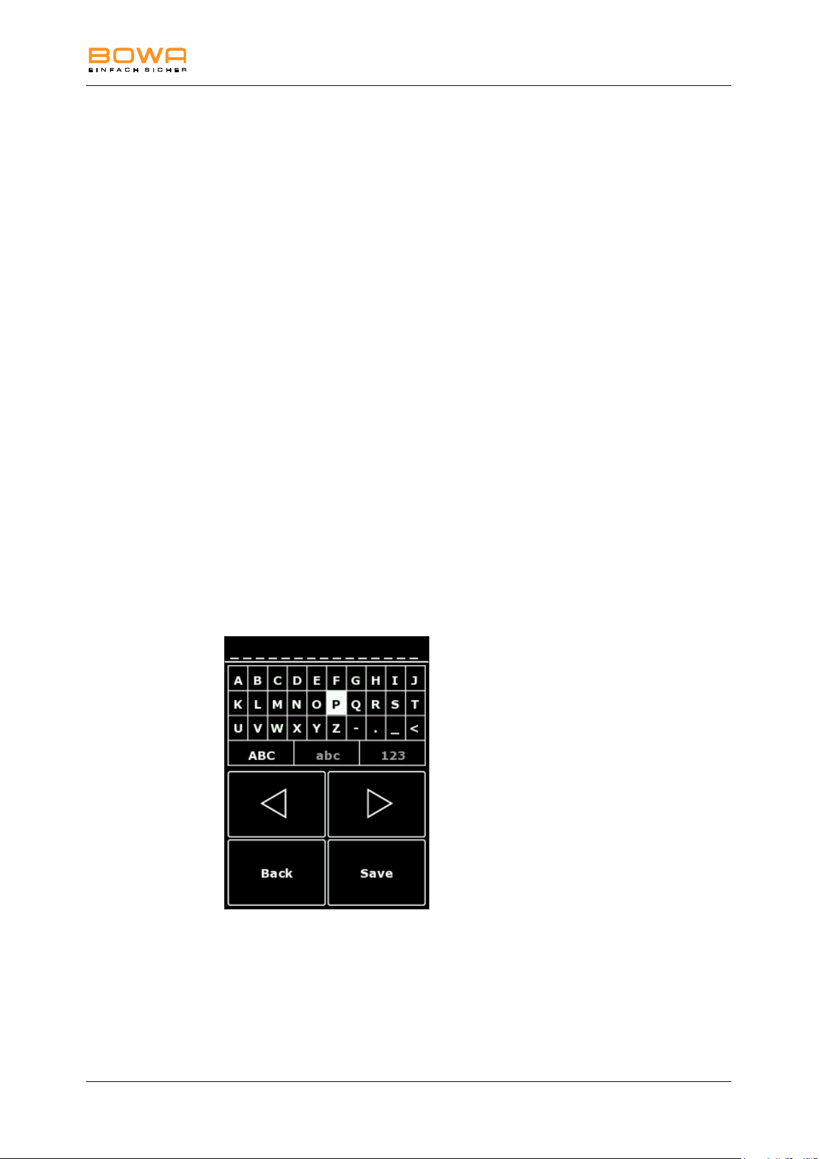
5 Operation
Delete Program
1. Tap "Delete program" to enter the program list
The system displays a red highlighted list of stored programs.
The currently loaded program is visualized by the orange arrow.
4. Select the program to be deleted with the arrow keys.
5. Confirm the selection with the "OK" button.
The main screen is displayed.
- orTo return to the main screen without changing the selection, select "Back" or
tap any button outside the selection menu.
Sort program
1. Tap “Sort program“ to sort the programs alphabetically, by favourites or by
storage date.
2. Select the required order by tapping on the desired parameter.
The “Program“ dialog is displayed.
Save program
1. Tap "Save program" to save the current setting under the same or another
program name.
2. Choose "Save" to maintain the same program name for the current setting.
- orSelect "Save As" to place a new program name for the current setting.
Figure 5-17: "Save program" dialog
In this menu, program names can be created. Several symbols, capital or small
letters or numbers are selection options.
The navigation is possible using the arrow keys.
Select the letter with "OK".
The selection is confirmed using "Save".
Use the ”Back” button to return to the main screen
900-351_IFU_V2.0.0_20221-S0-20150520-EN Operating Manual ARC 350 59
Page 60
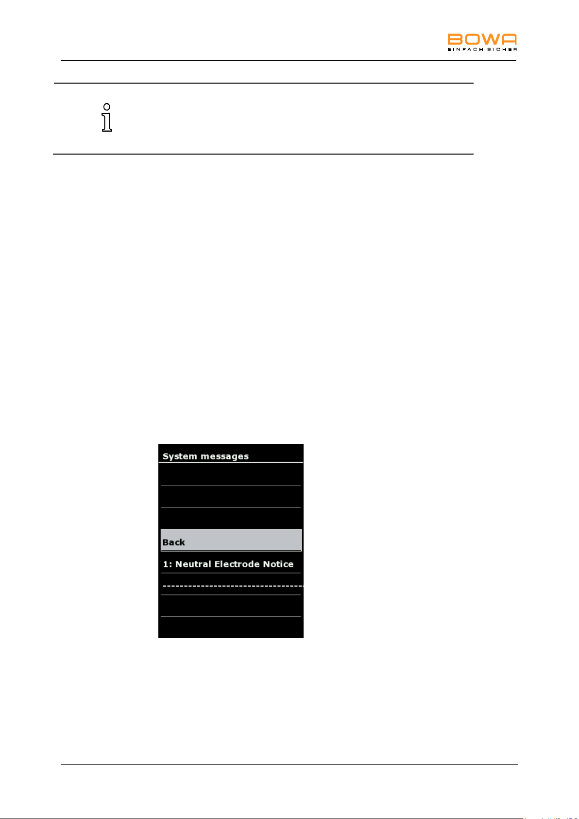
5 Operation
The following basic programs are provided with the full version of
ARC 350 (incl. the options GastroCut, Bipolar Resection and
LIGATION): Argon flex, Argon, Cardiac, GastroCut, Laparoscopy, Macro,
Micro, Open Surgery, Resection bipolar, Resection monopolar,
SimCoag, Standard
5.10.5. “Language“ dialog
The following languages are selectable in „language selection“:
German, English, French, Italian, Spanish, Russian, Polish, Turkish, Czech,
Portuguese
5.10.6. "System messages" dialog
In the "System messages" dialog, it is possible to open the saved system
messages which have occurred since switching on the HF device.
These messages are not saved when switching off the HF device.
Opening saved system messages:
1. Select a system message.
2. Tap ”OK” to open the system message again.
3. Press again "OK" to return to the overview.
4. To return to the main screen without changing the selection, tap any button
outside the selection menu.
Figure 5-18: “System messages“ dialog
60 Operating Manual ARC 350 900-351_IFU_V2.0.0_20221-S0-20150520-EN
Page 61
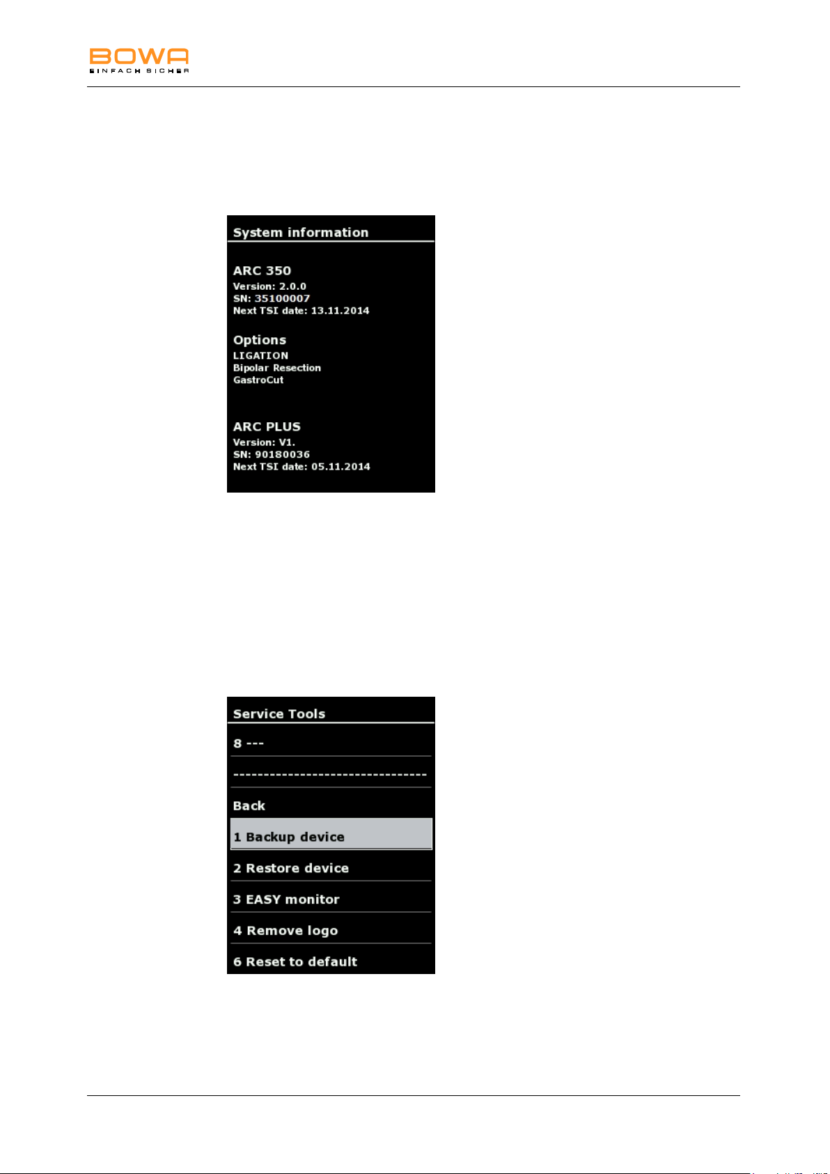
5 Operation
5.10.7. “System information“ dialog
The “System information“ dialog displays various system parameters such as
version, serial number, TSI dates for ARC 350 and ARC PLUS, as well as options.
Figure 5-19: “System information“ dialog
See also technical safety inspection (TSI), page 71.
5.10.8. "Service" dialog
In the "Service" dialog contact detail are displayed, after entering a password, you
can use the dialog to access additional options.
With the password 001224 you enter the service level.
Figure 5-20: “Service tools“ dialog
900-351_IFU_V2.0.0_20221-S0-20150520-EN Operating Manual ARC 350 61
Page 62

5 Operation
Saving device settings
With the function "Backup device" device settings can be saved on the BOWA
USB Stick (REF 900-402). This includes all stored programs and system settings.
Transferring device settings
Use "Restore device" to transfer saved device settings from a BOWA USB Stick
(REF 900-402) to the ARC 350 unit.
EASY resistance monitor
With "EASY monitor" the resistance at the neutral electrode is displayed.
Configuring the startup screen
In ARC 350 is a possibility to create a personalized startup screen. This appears
after switching on the device for a selectable duration.
1. Create a folder with the name "arc_logo" on the USB flash drive
(REF 900-402).
2. Open the Windows program " Notepad.exe " and enter a number between 5
and 60 for the displayed duration in seconds.
3. Save this file on the USB flash drive in the folder "arc_logo" under the name
"KH_Logo.conf". Make sure that the file is stored as type "All Files ( *. *)" and
encoding "UTF -8".
4. Create a startup screen with a resolution of 240 x 320 pixels and save it under
the name "KH_Logo_arc350.png" in the folder "arc_logo".
5. Plug the USB flash drive with the files created in the USB port of the ARC 400
and turn the unit on using the main switch.
6. Wait until the ARC 350 is fully booted and the user interface appears.
7. Turn on the ARC 350 and remove your USB flash drive.
Now your generated startup screen is permanently stored in the device and
appears after every switching-on for the specified duration.
In the service menu, the stored startup screen can be deleted using
"Remove logo".
Resetting to factory settings
The "Reset to default" function allows you to reset all settings and programs to
factory settings.
62 Operating Manual ARC 350 900-351_IFU_V2.0.0_20221-S0-20150520-EN
Page 63
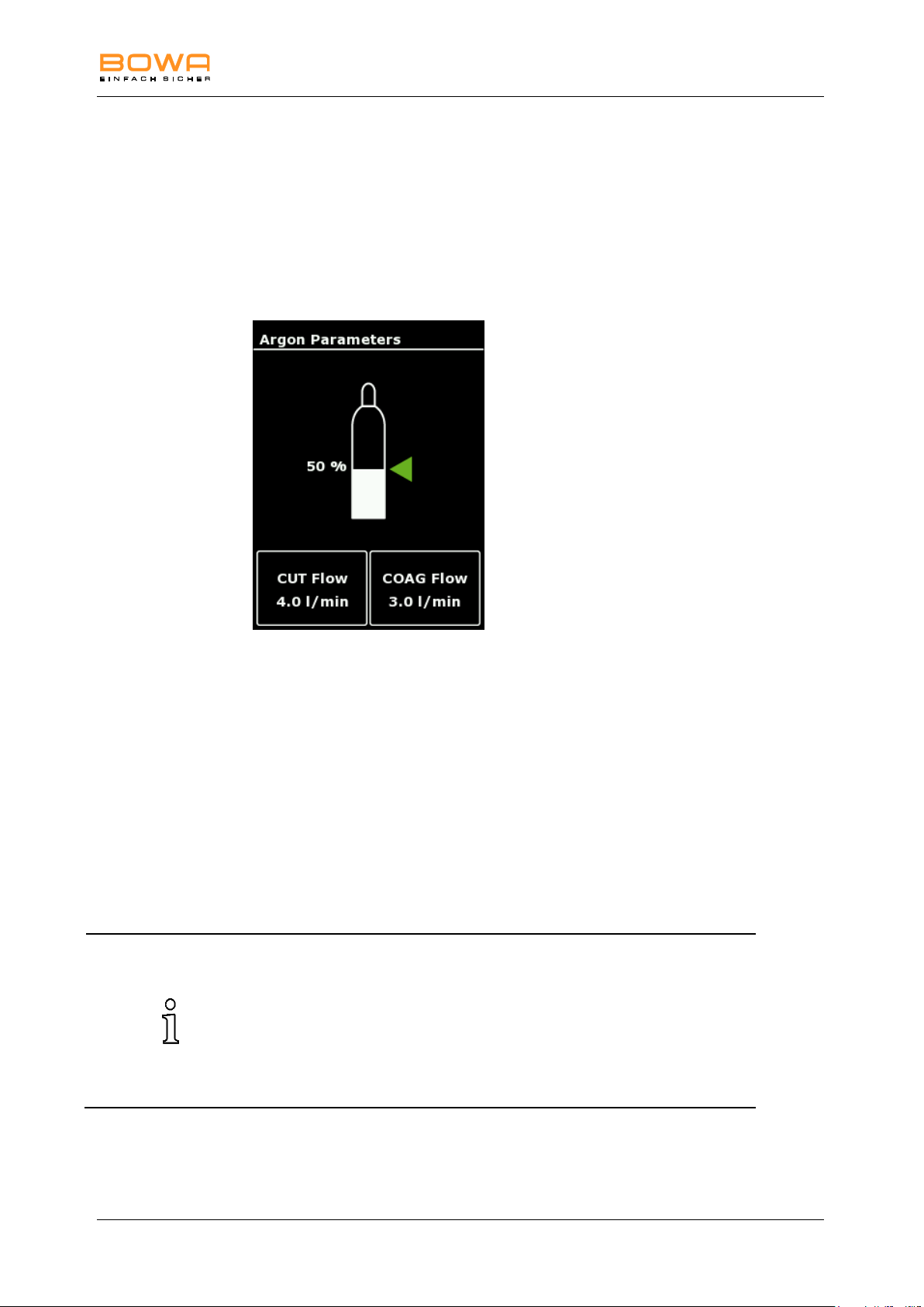
5 Operation
Default settings for argon flow rates according to the different modes are
selected automatically:
Argon open:
CUT flow rate: 4.0 l/min
COAG flow rate: 3.0 l/min
Argon flexible:
COAG flow rate: 0.4 l/min
5.10.9. "Argon" dialog
In case of the selection of an argon mode and a successful connection to ARC
PLUS, the main screen displays an argon dialog with currently stored flow rates for
cutting and coagulation.
The "Argon" dialog enables the selection of argon flow rates for cutting and
coagulation, as well as the selection of argon bottles and the display of filling
levels.
Figure 5-21: "Argon" dialog
1. Select the “Argon” menu by tapping the display of the flow rates.
The current filling level of the argon gas bottle is displayed when using a
pressure reducer with electronic pressure sensor.
2. Select the variable flow rate for cutting (CUT flow) or coagulation
(COAG flow).
3. Set the argon flow rate by using the arrow keys.
4. Confirm your selection by pressing the "OK" button.
- or Press the "Back" button to return to the main screen without changing the
selection.
900-351_IFU_V2.0.0_20221-S0-20150520-EN Operating Manual ARC 350 63
Page 64
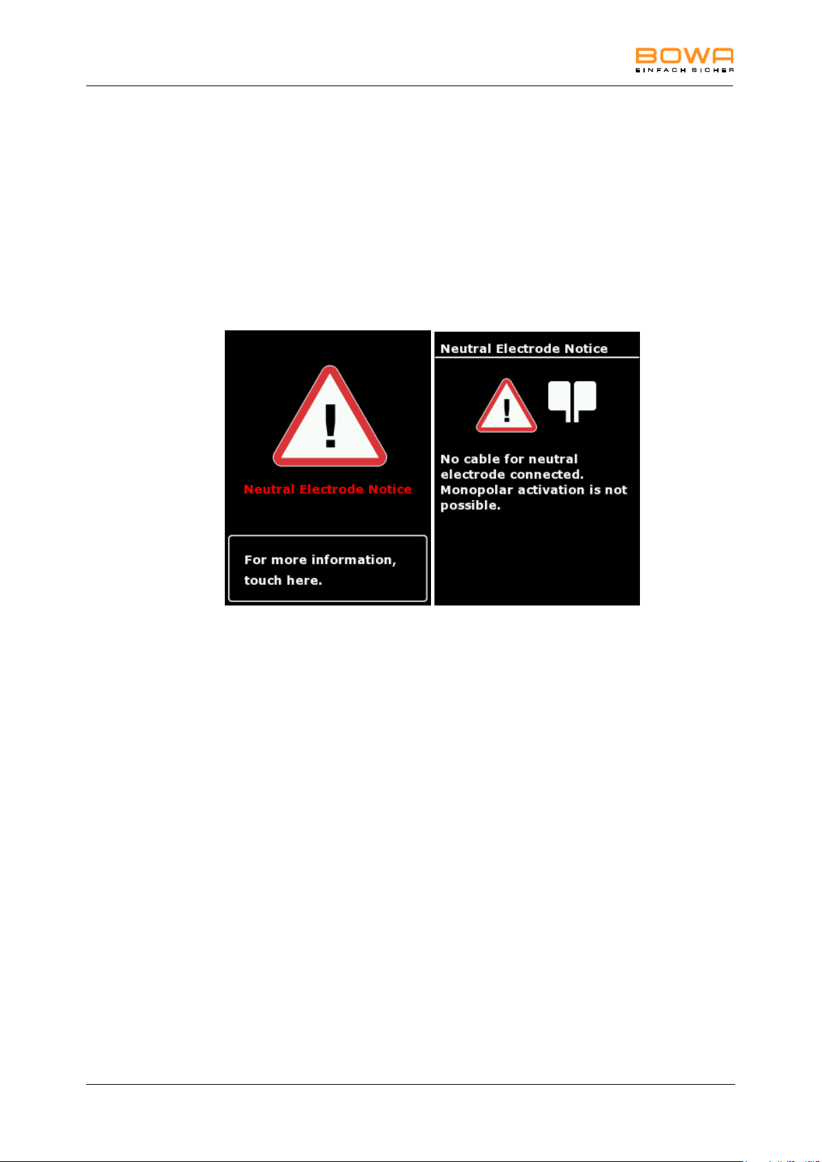
6 Detecting and correcting faults
6. Detecting and correcting faults
Two types of faults can occur:
system faults
EASY monitoring faults
6.1. System informations
A warning message appears on the display when a system fault occurs.
Figure 6-1: Confirmation neutral electrode
Further information to the cause and corrective measures for this message are
available pressing the lower area of the screen.
System informations have three different categories:
Notice (grey screen)
Warning (orange screen)
Error (red screen)
While an error is present, activations are prohibited.
The message is available using the orange marked „?“ in the system bar.
Moreover, these messages are available in the menu program system settings and
will be deleted when switching off the unit.
64 Operating Manual ARC 350 900-351_IFU_V2.0.0_20221-S0-20150520-EN
Page 65

6 Detecting and correcting faults
Heading
Fault message
Confirmation of
AUTOSTART Mode
You have selected an AUTOSTART mode.
Setting the AUTOSTART mode can result in unintentional
coagulations, e.g. when bipolar forceps are used for gripping while
the AUTOSTART Mode is on.
AUTOSTART Error
The instrument is in contact with tissue.
AUTOSTART cannot be selected when the instrument is in contact
with tissue. Open up the instrument.
TSI Warning
The annual Technical Safety Inspection (TSI) is due.
Neutral Electrode
Error
No neutral electrode connected.
No neutral electrode connected. Connect a neutral electrode.
Neutral Electrode
Error
Wrong neutral electrode connected..
The selection does not match the neutral electrode connected.
Connect the neutral electrode which matches the selected mode, or
change the mode to match the neutral electrode.
Neutral Electrode
Error
Poor contact with the patient.
The resistance between the neutral electrode and the patient is too
high. Establish better contact of the neutral electrode.
Neutral Electrode
Warning
Poor contact with the patient.
The contact resistance between the neutral electrode and the
patient is increasing.
Establish better contact of the neutral electrode.
Neutral Electrode
Error
No cable for neutral electrode connected.
No cable for neutral electrode connected. Connect a cable for
neutral electrodes.
Neutral Electrode
Notice
No cable for neutral electrode connected.
The cable for neutral electrode has been removed. Monopolar
activation is not possible.
Mode Error
No mode selected.
No mode was selected for this type of activation.
Select the desired mode or change the foot switch assignment.
Mode Error
This mode is not allowed for baby neutral electrodes. Use split
neutral electrodes with a large conductive surface for this mode.
Mode Error
This mode is not allowed for this socket. The current mode remains
active. Choose another socket for this mode.
Foot Switch Error
Foot switch not assigned to a socket.
The foot switch has not been assigned to a socket yet.
Assign a socket to the foot switch using the "Pedal" button.
The following table describes the cause of the fault and the appropriate corrective
action.
900-351_IFU_V2.0.0_20221-S0-20150520-EN Operating Manual ARC 350 65
Page 66

6 Detecting and correcting faults
Heading
Fault message
Foot Switch Notice
The assignation of the foot switch has been changed.
The orange button on the foot switch enables switching from socket
A to B and back. The active foot switch assignation is displayed in
the form of an orange dot.
Foot Switch Warning
Second foot switch assignment has not been set.
There is no second foot switch assignment in place.
The current assignment remains active.
To allocate the second foot switch assignment press the "Pedal"
push button on the desired socket.
Foot Switch Error
Fault on foot switch connection.
Check the foot switch. If this message appears again, please
contact the Technical Support. Internet: www.bowa.de Telephone:
+49707260020
Finger Switch Error
Fault on finger switch connection.
Check the handle and the connection cable. Please replace them if
damaged. If this message appears again please contact the
Technical Support. Internet: www.bowa.de Telephone:
+49707260020
Finger Switch Error
Fault on finger switch connection.
Check the handle and the connection cable. Please replace them if
damaged. Instruments with one pin have to be connected to the
marked socket. If this message appears again please contact the
Technical Support. Internet: www.bowa.de Telephone:
+49707260020
Finger Switch Error
Fault on finger switch connection.
Check the handle and the connection cable. Please replace them if
damaged. If this message appears again please contact the
Technical Support. Internet: www.bowa.de Telephone:
+49707260020
Temperature Warning
The temperature of the device is higher than normal.
The temperature of the device is elevated. This leads to a reduction
of the maximum power.
Limitation of
Continuous Activation
The maximum activation time has been exceeded.
Please only activate the generator in short intervals, in order to
avoid harming the patient and damaging the connected instruments
or the generator.
Mains Voltage Error
The mains voltage is too low.
Please ensure a constant mains voltage. If necessary, connect a
UPS (Uninterrupted Power Supply).
Activation Error
While switching on the device, there is an activation by foot switch,
finger switch or AUTOSTART.
Check the handles or foot switches for malfunctions.
Disconnect the handles / foot switches from the device. If the error
persists, please contact the Technical Support. Internet:
www.bowa.de Telephone: +49707260020
66 Operating Manual ARC 350 900-351_IFU_V2.0.0_20221-S0-20150520-EN
Page 67

6 Detecting and correcting faults
Heading
Fault message
Activation Error
There is an activation while connecting the foot switch or finger
switch.
Check the handles or foot switches for malfunctions.
Disconnect the handles / foot switch from the device. If the error
persists, please contact the Technical Support. Internet:
www.bowa.de Telephone: +49707260020
Activation Error
There is no instrument connected on the activated socket.
Connect an instrument on the designated socket.
Activation Warning
The mode for safety inspections is active. Activation is not possible.
Quit this mode before activating again.
Bipolar Resection
Warning
No activation of the bipolar resection.
Check the irrigation medium, the connection cable, the instrument
and the selected settings.
Make sure that NaCl is used as an irrigation medium.
GastroCut Notice
The polypectomy has been completed.
GastroCut Warning
Polypectomy snare not in contact with tissue, or check connection
cable at snare or generator. Please apply the snare and reactivate.
First of all establish contact between tissue and polypectomy snare,
or check the connection cable at the snare or the generator. Then
activate with the yellow foot pedal.
LIGATION Notice
The LIGATION has been completed.
LIGATION Warning
There is a short-circuit in the area of the sealing instrument. Please
check the instrument for foreign material or contact with other
objects.
The sealing point must be free of foreign objects.
LIGATION Warning
The sealing instrument is not in contact with tissue. Please grasp
tissue and reactivate LIGATION.
Check the connection between instrument and generator. To
perform LIGATION of vessel and tissue bundles it is necessary to
grasp tissue and close the sealing instrument before activating.
ARC PLUS Fault
Please check if the argon bottles are connected and open. Empty
bottles should be replaced. Subsequently restart ARC PLUS by
activating the flashing ""Purge"" button.
ARC PLUS Fault
The argon inlet pressure is too high.
Max. inlet pressure: <4.5bar
Close a source of argon gas in the appropriate pressure range.
Subsequently restart ARC PLUS by activating the flashing "Purge"
button.
ARC PLUS Fault
The argon inlet pressure has exceeded the permissible limits. Inlet
pressure range: 2 - 4.5bar
Close a source of argon gas in the appropriate pressure range.
Subsequently restart ARC PLUS by activating the flashing "Purge"
button.
ARC PLUS Warning
Please check if the argon bottles are connected and open. Empty
bottles should be replaced. Subsequently restart ARC PLUS by
activating the flashing "Purge" button.
900-351_IFU_V2.0.0_20221-S0-20150520-EN Operating Manual ARC 350 67
Page 68

6 Detecting and correcting faults
Heading
Fault message
ARC PLUS Warning
Mixed operation of argon bottles with and without an electric bottle
pressure gauge is not recommended
Connect two identical pressure reducers.
ARC PLUS Warning
Please check if the instrument is free of adhesions, and purge it with
argon.
If repeated purging does not solve the problem, the instrument and
cable must be replaced.
ARC PLUS Warning
The argon flow settings at ARC 350 are invalid
ARC PLUS Warning
The filling level of the argon bottle is low.
Please make sure that a replacement is available.
You can connect two argon bottles. The unit shifts automatically to
the second bottle.
ARC PLUS Fault
The argon bottle is empty.
Connect a replacement bottle to enable activation.
You can connect two argon bottles. The unit shifts automatically to
the second bottle
ARC PLUS Notice
The argon bottle is empty. The unit has shifted automatically to the
replacement bottle.
Please make sure that a replacement is available
TSI ARC PLUS
Warning
The annual Technical Safety Inspection (TSI) for ARC PLUS is due.
Plug'n Cut COMFORT
Notice
The lifetime of the instrument is ending soon.
Please order a replacement in good time.
Any use of the instrument beyond its lifetime is not covered by
warranty. Please contact your BOWA dealer in good time to
purchase a new instrument.
Plug'n Cut COMFORT
Warning
The maximum lifetime of the instrument has been reached. Any
further use is not covered by warranty. The maximum service
lifetime of the instruments must not be exceeded, in order to
guarantee safe usage. Any further use is at the user's risk.
Plug'n Cut COMFORT
Notice
You have connected a BOWA RFID instrument. X applications
remain available. The maximum lifetime of the instruments must not
be exceeded, in order to guarantee safe usage. Any further use is at
the user's risk.
Dr. Dongle Notice
You can save up to six of your preferred programs on your Dr.
Dongle and run them in a flexible way. With the "Load" button you
can call a selected program. You can use the "Save" button to enter
an explanatory text for the selected program.
Plug'n Cut COMFORT
Warning
A software update is necessary to use Plug'n Cut COMFORT with
this instrument. Only carry out manual settings at this instrument.
Please contact the Technical Support. Internet: www.bowa.de
Telephone: +49707260020
Internal Error 4177
If this message appears again, please contact the Technical
Support. Internet: www.bowa.de Telephone: +49707260020
Internal Errors have a number next to the description.
Please advise the Technical Service of this number.
68 Operating Manual ARC 350 900-351_IFU_V2.0.0_20221-S0-20150520-EN
Page 69

6 Detecting and correcting faults
EASY
monitoring
Cause
Indication
Corrective measures
Flashes yellow
Significant increase in
resistance
Depending on the
indication, there may be
heating under the neutral
electrode
–
Stopping the application is
not necessary.
Check the proper
application of the neutral
electrode.
Switches from
green to
continuous red
A significant problem
occurred when the
monopolar current was
activated
An acoustic
signal sounds.
A warning
message
appears on the
display
Check the neutral
electrode and neutral
electrode cable (see
Section EASY
neutral electrode
monitoring (EASY
monitoring), page 28.
Check the neutral
electrode cable for
proper connection and
external damage.
Loosened electrode
An acoustic
signal sounds.
A warning
message
appears on the
display
Reattach the neutral
electrode. If the fault
persists, replace the
neutral electrode.
6.2. Fault indications for EASY monitoring
Fault indications are displayed in three stages (green, yellow and red) when
problems occur.
When working with a split neutral electrode, the following faults may occur:
900-351_IFU_V2.0.0_20221-S0-20150520-EN Operating Manual ARC 350 69
Page 70
7 Preparation
NOTE
Incorrect handling of the HF device can cause damage to the unit!
Never sterilize the ARC 350 device. Instead, clean or disinfect it.
WARNING
Risk of electric shock and fire!
Unplug the power connection before cleaning the device.
For cleaning surfaces, use the approved cleaning
agents/disinfectants only as specified by the manufacturer.
Ensure that no liquid penetrates the device.
Ensure that the AUTOSTART function is deactivated.
7. Preparation
7.1. Preparation of the accessories
Prepare the accessories (e.g. surgical handles, instruments, active
electrodes, neutral electrodes and cables) as described in the corresponding
operating manuals.
Check the accessories before and after use for damage and to ensure that
they are working properly.
7.2. Disinfection and cleaning
1. Apply the cleaning agent and disinfectant.
2. Wipe the agent off with a sponge moistened with clean water or with a cloth.
3. Dry the device using a clean, lint-free cloth.
70 Operating Manual ARC 350 900-351_IFU_V2.0.0_20221-S0-20150520-EN
Page 71

8 Maintenance and repair
DANGER
Infection hazard!
Carry out a surface disinfection and wrap the device in addition to
the shipping packaging material before allowing the device to leave
the hospital or office to avoid spreading germs and infections.
Any shorter safety inspection cycles specified in national regulations
must be observed.
8. Maintenance and repair
8.1. Maintenance
Check the device, the device trolley and the accessories (e.g. foot switch,
cable) after each use for damage or defects. In particular, make sure that the
insulation is intact on all cables.
Do not use any damaged device, damaged device trolley or damaged
accessories.
Replace defective accessories immediately.
Have the safety inspection for the device performed once a year. Please
consult and comply with the respective service instructions for additional
technical information.
8.1.1. Safety inspection
Safety inspections must be performed once a year.
The next safety inspection date of ARC 400 can be displayed in the dialog,
see “BOWA Service” dialog, page 61
A warning message appears during system start-up if a safety inspection is
due. Further work is still possible, confirm this with “OK”.
The device and accessories may be inspected only by persons who have the
required training, knowledge or experience and who can perform the
inspection independently.
With regard to the safety inspection, you must comply with the country-
specific rules and regulations.
The inspector documents the inspection results and measured values
corresponding to the printed inspection protocol.
In the case of severe deviations from the values of the attached final acceptance
report, or if the specified maximum values were exceeded:
Send the HF device to the service centre, see section Technical service,
page 73.
900-351_IFU_V2.0.0_20221-S0-20150520-EN Operating Manual ARC 350 71
Page 72

8 Maintenance and repair
NOTE
You can damage the HF device by doing your own repairs and
modifications of medical equipment!
If a repair is necessary, contact the service address mentioned in
chapter 9.1.
Never carry out any repairs yourself.
Fast and satisfactory repairs can only be guaranteed when all required
data have been supplied in full.
8.2. Repairs
BOWA is liable for safety, reliability and performance of the HF device under the
following conditions:
Full compliance with all instructions regarding the installation and
proper use for the intended purpose contained in this operating manual
was maintained.
Changes, repairs, new settings and similar procedures were carried out
only by persons authorized to do this work by BOWA.
The electrical installations in the relevant room meet the local
requirements and statutory provisions.
The following information is required for returning the device:
complete address
model number
serial number
software version
Describe the problem, the appropriate application and the accessories used.
– or –
Describe the repairs to be made.
72 Operating Manual ARC 350 900-351_IFU_V2.0.0_20221-S0-20150520-EN
Page 73

9 Storage
9. Storage
If you store the HF device for longer that one year, pay specific attention to
the indicators during automatic functional testing, see section Functional test,
page 26.
Clean the HF device thoroughly before you put it into storage.
Store the HF device in a clean, dry place in accordance with the storage
conditions.
Storage conditions:
Temperature: -20 °C to +50 °C
Relative humidity 0 to 75 %, non-condensing
Atmospheric pressure: 500 to 1060 hPa
9.1. Technical service
Contact the following service center for maintenance and repair work:
BOWA-electronic GmbH & Co. KG
Heinrich-Hertz-Strasse 4–10
72810 Gomaringen, Germany
Phone +49 (0) 7072-6002-0
Fax +49 (0) 7072-6002-33
Email [email protected]
or visit our website:
www.bowa.de
900-351_IFU_V2.0.0_20221-S0-20150520-EN Operating Manual ARC 350 73
Page 74
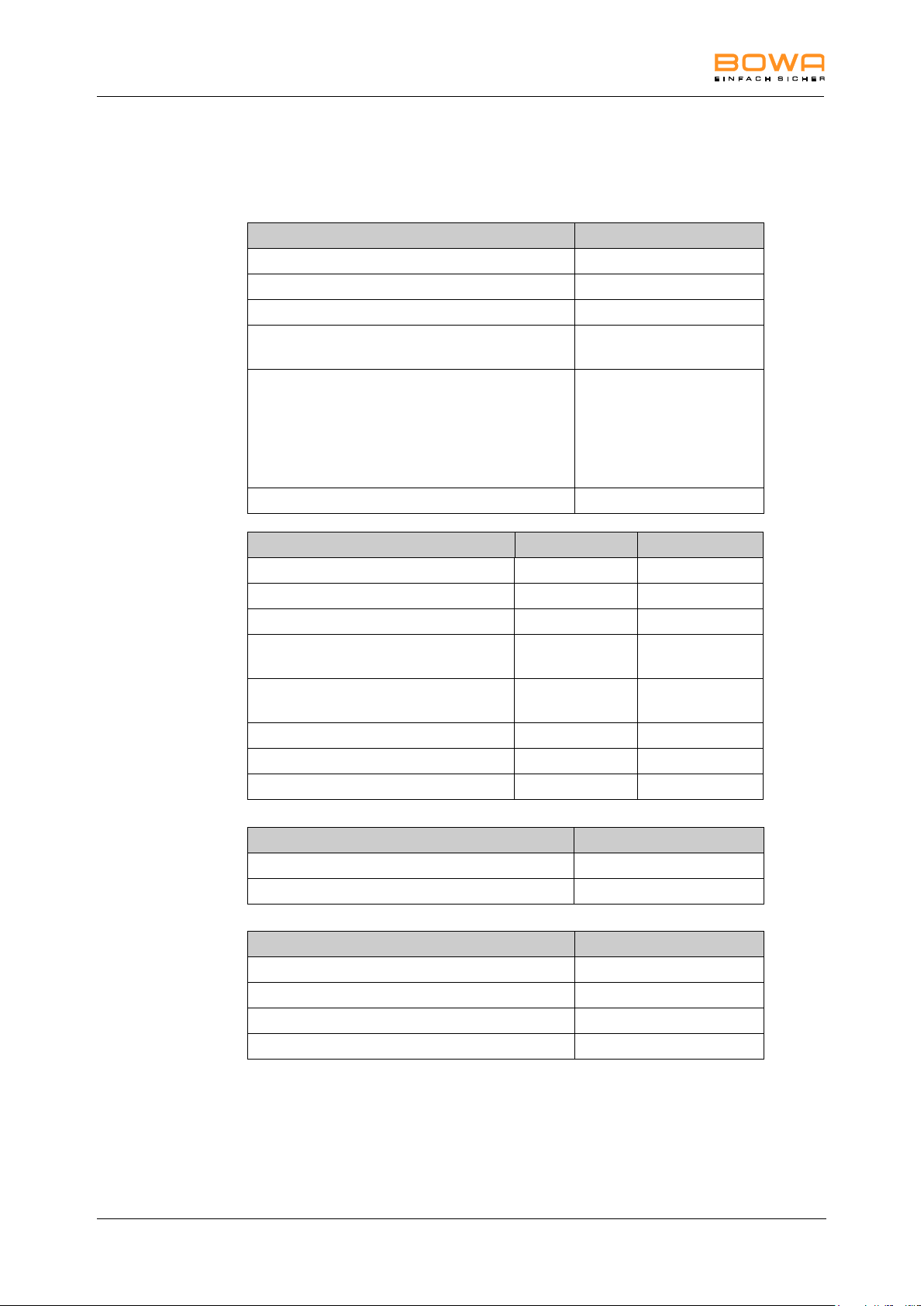
10 Technical specifications
Insulation type / Classification
EMC
IEC 60601-1-2
Level of protection provided by the housing
IP 21
Protection class according to EN 60601-1
I
Application component type according to
EN 60601-1
CF
Standards compliance
IEC 60601-1: 2005,
IEC 60601-1-2: 2007,
IEC 60601-2-2: 2009,
ISO 14971: 2007,
ISO 13485: 2003 +
Cor.1_2009
Classification according to EC Directive 93/42/EEC
IIb
Power connection
220 V - 240 V
100 V - 115 V
Power consumption in standby mode
3 W / 40 VA
3 W / 40 VA
Current consumption in standby mode
200 mA
400 mA
Maximum power consumption (at 350 W)
700 W / 1150 VA
700 W / 1150 VA
Maximum current consumption (at 350
W)
5 A
10 A
Line fuses
2 x 5 A slow-blow
2 x 10 A slowblow
Input voltage range
198 V to 264 V
90 V to 130 V
Line frequency
50 / 60 Hz
50 / 60 Hz
Terminal for potential equalization
Dimensions and weight
External dimensions: width x height x depth (mm)
430 x 180 x 475
Weight
approx. 12.5 kg
Programs
Number of programs in the device
350
Default programs, factory set
Individually programmable
Program number and data shown on the display
10. Technical specifications
10.1. ARC 350 technical data
74 Operating Manual ARC 350 900-351_IFU_V2.0.0_20221-S0-20150520-EN
Page 75
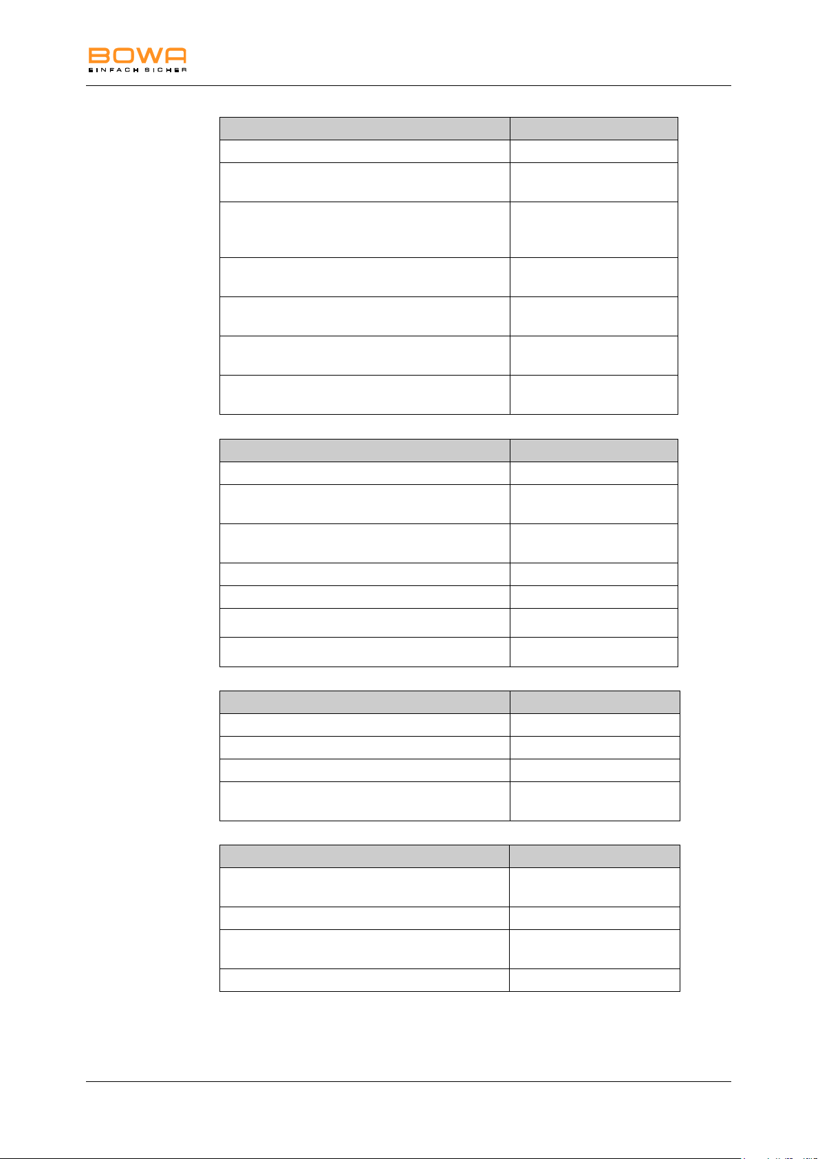
10 Technical specifications
Neutral electrode monitoring
EASY (Electrode Application System)
Display indication of one-piece or split or Baby
electrode in the main and neutral electrode menu
Contact resistance between individual sections of
split neutral electrodes shown on display with
column for control
Lead resistance shown on the display when a onepiece neutral electrode is used
Maximum allowable resistance between the
sections of a split electrode
300 Ω
Warning signal for hazardous conditions beneath
the neutral electrode
Visual, acoustic
Warning messages on display:
Text messages with further
information
Safety features
ISSys (Integrated Safety System)
Continuous monitoring of HF leakage current with
fault indication
Text messages with further
information
Dosage monitoring with fault indication on the
display
Continuous self-test
Continuous status indication on the display
Operating errors shown on the display
Text messages with further
information
System faults shown on the display
Text messages with further
information
Documentation
Data acquisition and storage in the device
System information with date
Fault states
Operating errors
Data retrieval via the display
Text messages with further
information
Communication
External interface for communication with ARC
PLUS (light wire cables)
USB interface for software updates
External PC interface, UART, using BOWA
software
Service support using BOWA software
900-351_IFU_V2.0.0_20221-S0-20150520-EN Operating Manual ARC 350 75
Page 76
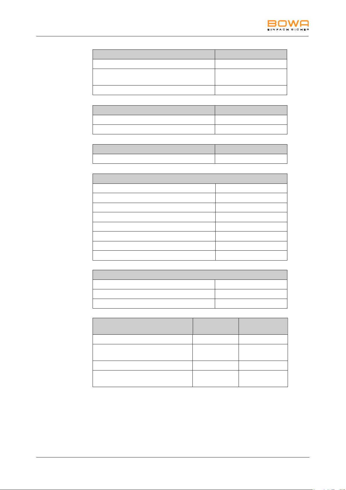
10 Technical specifications
Service support
Network port for service support
Service support by service programs integrated in
the device
Service support via ISSys
Cooling
Convection
Temperature-controlled fan
Duty factor
Intermittent
10 s / 30 s (on/off)
Characteristics
Max. CUT Power (at 500 Ω)
350 W
Max. COAG Power (at 25 Ω)
350 W
Monopolar sockets
2 x international / Erbe
Bipolar sockets
2 x international / Erbe
Connection for footswitch
2 x
AUTOSTART
Bipolar finger switch
Plug’n Cut COMFORT instrument identification
Optionen
Argon / GastroCut
REF 900-391
Bipolar Resection
REF 900-395
LIGATION
REF 900-396
Umweltbedingungen
Betrieb
Transport und
Lagerung
Temperature
+10°C to +40°C
-20°C to +50°C
Relative humidity
30 to 75%, noncondensing
0 to 90%, noncondensing
Atmospheric pressure
700 to 1060 hPa
500 to 1060 hPa
Operating altitude (max)
4000 m a. sea
level
76 Operating Manual ARC 350 900-351_IFU_V2.0.0_20221-S0-20150520-EN
Page 77

10 Technical specifications
Description
CCS
ARC
CONTROL
Form of HF
voltage
Max. power output
Peak
voltage
Default values
Effect
Power range
Effect
Max. Watt
Modes Monopolar Cutting
Standard
Yes
Yes
sinusoidal
constant
1
2
3
4
5
6
7
8
9
1 W - 350 W
400 Vp
450 Vp
560 Vp
650 Vp
650 Vp
700 Vp
700 Vp
700 Vp
750 Vp
5
100
Micro
Yes
yes
sinusoidal
constant
1
2
3
4
5
6
7
8
9
1 W - 50 W
280 Vp
340 Vp
380 Vp
400 Vp
400 Vp
400 Vp
450 Vp
450 Vp
450 Vp
5
20
Dry
Yes
yes
sinusoidal
modulated
1
2
3
4
5
6
7
8
9
1 W - 200 W
1.4 kVp
1.4 kVp
1.4 kVp
1.4 kVp
1.5 kVp
1.6 kVp
1.6 kVp
1.6 kVp
1.6 kVp
5
100
Argon
Yes
yes
sinusoidal
constant
1
2
3
4
5
6
7
8
9
1 W - 300 W
400 Vp
450 Vp
560 Vp
650 Vp
650 Vp
700 Vp
700 Vp
700 Vp
750 Vp
5
100
Resection
Yes
yes
sinusoidal
constant
1
2
3
4
5
250 W
650 Vp
700 Vp
700 Vp
700 Vp
750 Vp
2
---
MetraLOOP
Yes
Yes
sinusoidal
constant
1
2
3
100 W
150 W
200 W
650 Vp 1 ---
Laparoscopy
Yes
Yes
sinusoidal
constant
1
2
3
4
5
6
7
8
9
1 W - 200W
400 Vp
450 Vp
560 Vp
650 Vp
650 Vp
700 Vp
700 Vp
700 Vp
750 Vp
5
100
GastroLOOP
1
Yes
Yes
sinusoidal
alternating
Coag, Cut
and break
phases
1
2
3
4
5
6
7
8
9
-
750 Vp 5 ---
GastroLOOP
2
Yes
Yes
sinusoidal
alternating
Coag, Cut
and break
phases
1
2
3
4
5
6
7
8
9
-
750 Vp 5 ---
900-351_IFU_V2.0.0_20221-S0-20150520-EN Operating Manual ARC 350 77
Page 78

10 Technical specifications
Description
CCS
ARC
CONTROL
Form of HF
voltage
Max. power output
Peak
voltage
Default values
Effect
Power range
Effect
Max. Watt
Modes Monopolar Cutting
GastroLOOP
3
Yes
Yes
sinusoidal
alternating
Coag, Cut
and break
phases
1
2
3
4
5
6
7
8
9
-
750 Vp 5 ---
GastroKKNIF
E 1
Yes
Yes
sinusoidal
alternating
Coag and Cut
phases
1
2
3
4
5
6
7
8
9
-
650 Vp 5 ---
GastroKNIFE
2
Yes
Yes
sinusoidal
alternating
Coag and Cut
phases
1
2
3
4
5
6
7
8
9
-
650 Vp 5 ---
GastroKNIFE
3
Yes
Yes
sinusoidal
alternating
Coag and Cut
phases
1
2
3
4
5
6
7
8
9
-
650 Vp 5 ---
Modes Monopolar Coagulation
Moderate
sinusodial
constant
1
2 3 1 W - 120 W
250 Vp 2 60
Forced non
cutting
pulsed
modulated
-
1 W - 80 W
3.5 kVp
---
50
Forced mixed
sinusoidal
modulated
1
2 3 1 W - 120 W
2.3 kVp
2.5 kVp
2.8 kVp
2
60
Forced cutting
sinusoidal
modulated
1
2
3
4
1 W - 250 W
1.5 kVp
1.5 kVp
1.3 kVp
1.3 kVp
2
80
Spray
pulsed
modulated
1
2
3
4
1 W - 120 W
3.0 kVp
3.8 kVp
4.6 kVp
5.0 kVp
2
80
Argon open
pulsed
modulated
-
1 W - 120 W
4.6 kVp
---
80
Argon flexible
pulsed
modulated
-
1 W - 120 W
4.4 kVp
---
40
78 Operating Manual ARC 350 900-351_IFU_V2.0.0_20221-S0-20150520-EN
Page 79

10 Technical specifications
Description
CCS
ARC
CONTROL
Form of HF
voltage
Max. power output
Peak
voltage
Default values
Effect
Power range
Effect
Max. Watt
Modes Monopolar Coagulation
Argon flex.
pulse
pulsed
modulated
1
2 3 1 W – 80 W
4.4 kVp 2 20
Resection
sinusoidal
modulated
-
1 W -120 W
2.6 kVp
---
60
Cardiac
Mammary
sinusoidal
modulated
-
1 W - 60 W
2.3 kVp
---
15
Cardiac
Thorax
sinusoidal
modulated
-
1 W - 100 W
2.3 kVp
---
40
SimCoag
sinusoidal
modulated
pulsed
modulated
pulsed
modulated
1
2 3 1 W - 120 W
1.5 kVp
2.3 kVp
4.6 kVp
2
60
Gastro Coag
sinusoidal
modulated
1
2 3 1 W - 50 W
2.3 kVp
2.6 kVp
3.1 kVp
2
15
Laparoscopy
sinusoidal
modulated
-
1 W - 120 W
1.8 kVp
---
60
Modes Bipolar Cutting
Standard
Yes
Yes
sinusoidal
constant
-
1 W - 200 W
400 Vp
---
100
Bipolar
resection
Yes
Yes
sinusoidal
constant
1
2 3 250 W
500 Vp 2 ---
Bipolar
scissors
sinusoidal
constant
-
1 W - 120 W
200 Vp
---
60
Modes Bipolar Coagulation
Standard
forceps
sinusoidal
constant
-
1 W - 120 W
150 Vp
---
40
Standard
forceps
AUTO
sinusoidal
constant
-
5 W - 120 W
150 Vp
---
40
900-351_IFU_V2.0.0_20221-S0-20150520-EN Operating Manual ARC 350 79
Page 80

10 Technical specifications
Description
CCS
ARC
CONTROL
Form of HF
voltage
Max. power output
Peak
voltage
Default values
Effect
Power range
Effect
Max. Watt
Modes Bipolar Coagulation
Micro forceps
sinusoidal
constant
-
0.1 W - 20 W
150 Vp
---
10
Forceps
forced
sinusoidal
modulated
-
1 W - 100 W
550 Vp
---
70
LIGATION
sinusoidal
modulated
-
200 W
190 Vp
---
---
TissueSeal
PLUS
sinusoidal
modulated
-
200 W
190 Vp
---
---
Bipolar
scissors
sinusoidal
constant
-
1 W - 120 W
200 Vp
---
60
Laparoscopy
sinusoidal
constant
-
1 W - 120 W
150 Vp
---
50
Bipolar
resection
sinusoidal
constant
-
1 W - 350 W
190 Vp
---
200
The max. values are not necessarily created at rated load resistance.
The HF power is subject to a tolerance limit of ± 20%.
80 Operating Manual ARC 350 900-351_IFU_V2.0.0_20221-S0-20150520-EN
Page 81
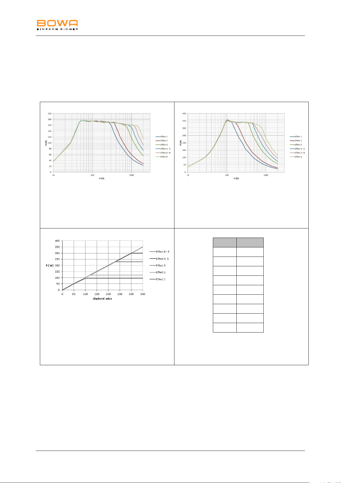
10 Technical specifications
Measurement at ohmic resistances
Diagram of power output P [W] as a
function of the load resistance R [] for
the setting "Monopolar Cutting
Standard"
= 175 W
Measurement at ohmic resistances
Diagram of power output P [W] as a
function of the load resistance R [] for
the setting "Monopolar Cutting
Standard"
= 350 W
Diagram of power output P [W] as a
function of the setting "Monopolar
Cutting Standard"
Rated load resistance = 500
Effect
U (Vp)
1
400
2
450
3
560
4
650
5
650
6
700
7
700
8
700
9
750
Table of HF output voltage U [Vp] as a
function of the setting "Monopolar
Cutting Standard" (idle mode)
10.2. Output, voltage and current diagrams
Monopolar Cutting – Standard
Pos: 53 /679-BOWA/HF-Geräte/ARC 300/
900-351_IFU_V2.0.0_20221-S0-20150520-EN Operating Manual ARC 350 81
Page 82
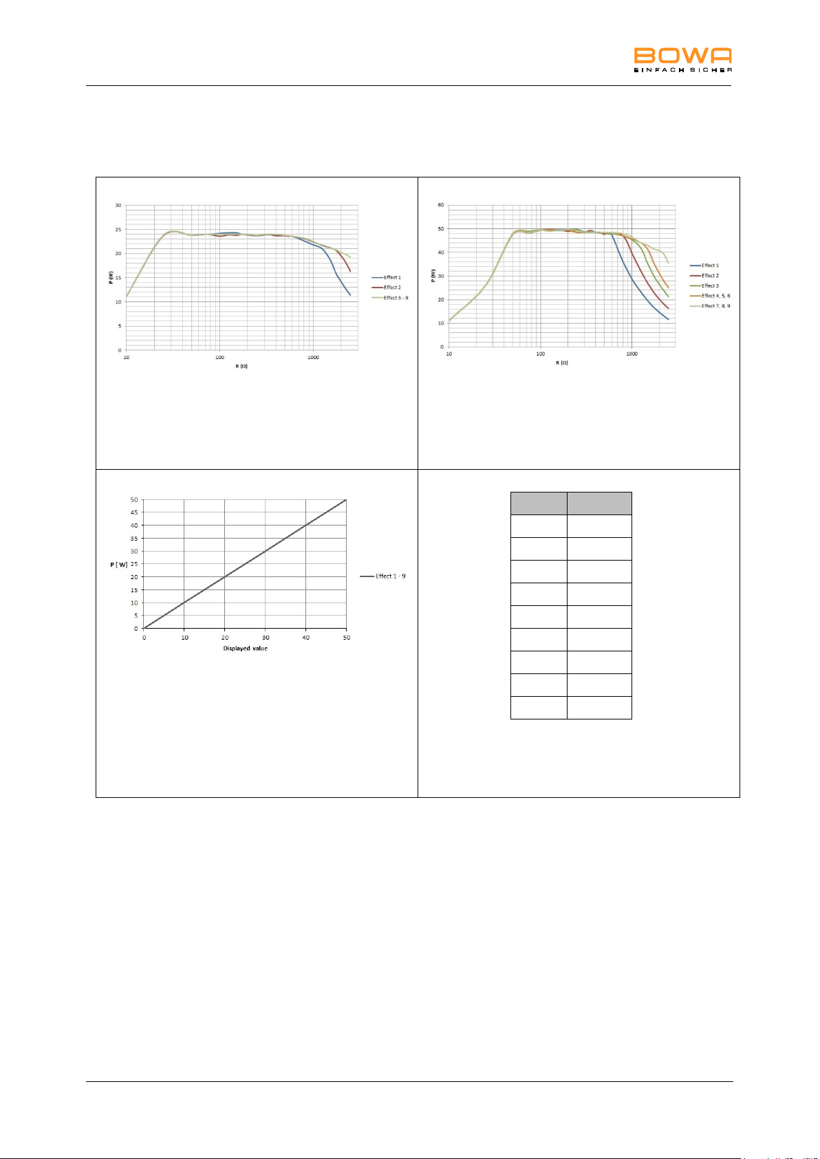
10 Technical specifications
Measurement at ohmic resistances
Diagram of power output P [W] as a
function of the load resistance R [] for
the setting "Monopolar Cutting Micro"
= 25 W
Measurement at ohmic resistances
Diagram of power output P [W] as a
function of the load resistance R [] for
the setting "Monopolar Cutting Micro"
= 50 W
Diagram of power output P [W] as a
function of the setting "Monopolar
Cutting Micro"
Rated load resistance = 500
Effect
U (Vp)
1
280
2
340
3
380
4
400
5
400
6
400
7
450
8
450
9
450
Table of HF output voltage U [Vp] as a
function of the setting "Monopolar
Cutting Micro" (idle mode)
Monopolar Cutting – Micro
82 Operating Manual ARC 350 900-351_IFU_V2.0.0_20221-S0-20150520-EN
Page 83
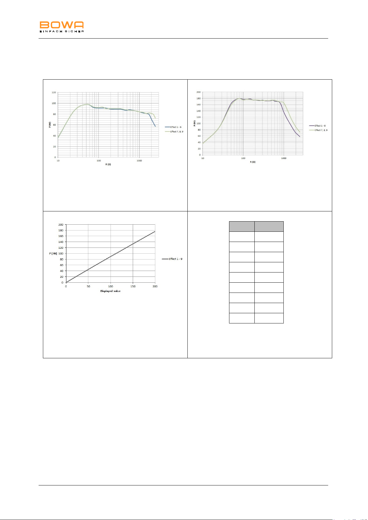
10 Technical specifications
Measurement at ohmic resistances
Diagram of power output P [W] as a
function of the load resistance R [] for
the setting "Monopolar Cutting Dry"
= 100 W
Measurement at ohmic resistances
Diagram of power output P [W] as a
function of the load resistance R [] for
the setting "Monopolar Cutting Dry"
= 200 W
Diagram of power output P [W] as a
function of the setting "Monopolar
Cutting Dry"
Rated load resistance = 500
Effect
U (Vp)
1
1400
2
1400
3
1400
4
1400
5
1500
6
1600
7
1600
8
1600
9
1600
Table of HF output voltage U [Vp] as a
function of the setting "Monopolar
Cutting Dry" (idle mode)
Monopolar Cutting – Dry
900-351_IFU_V2.0.0_20221-S0-20150520-EN Operating Manual ARC 350 83
Page 84
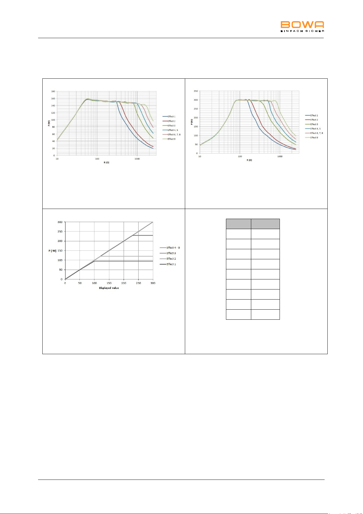
10 Technical specifications
Measurement at ohmic resistances
Diagram of power output P [W] as a
function of the load resistance R [] for
the setting "Monopolar Cutting Argon"
= 150 W
Measurement at ohmic resistances
Diagram of power output P [W] as a
function of the load resistance R [] for
the setting "Monopolar Cutting Argon"
= 300 W
Diagram of power output P [W] as a
function of the setting "Monopolar
Cutting Argon"
Rated load resistance= 500
Effect
U (Vp)
1
400
2
450
3
560
4
650
5
650
6
700
7
700
8
700
9
750
Table of HF output voltage U [Vp] as a
function of the setting "Monopolar
Cutting Argon" (idle mode)
Monopolar Cutting – Argon
84 Operating Manual ARC 350 900-351_IFU_V2.0.0_20221-S0-20150520-EN
Page 85
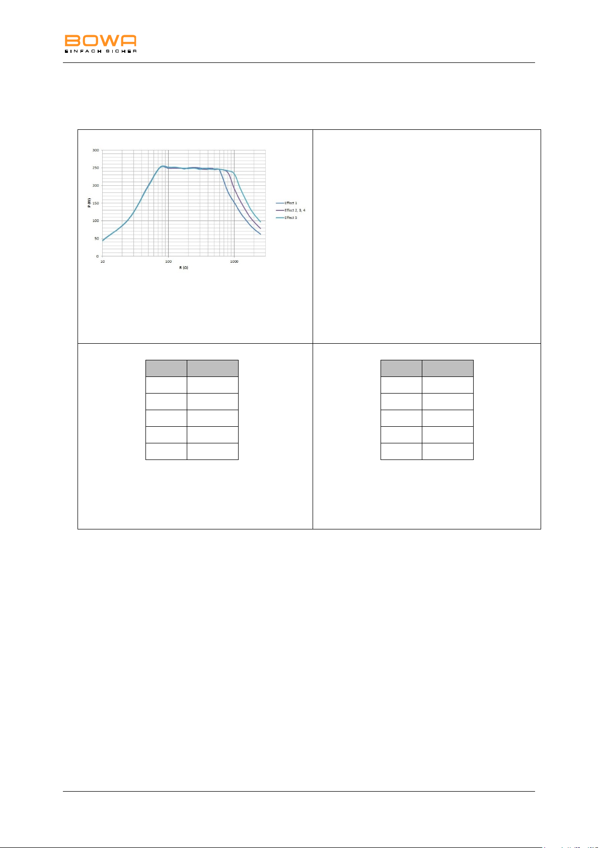
10 Technical specifications
Measurement at ohmic resistances
Diagram of power output P [W] as a
function of the load resistance R [] for
the setting "Monopolar Cutting
Resection"
Effect
P (W)
1
250
2
250
3
250
4
250
5
250
Table of power output P [W] as a
function of the setting "Monopolar
Cutting Resection"
Rated load resistance= 500
Effect
U (Vp)
1
650
2
700
3
700
4
700
5
750
Table of HF output voltage U [Vp] as
a function of the setting "Monopolar
Cutting Resection" (idle mode)
Monopolar Cutting – Resection
900-351_IFU_V2.0.0_20221-S0-20150520-EN Operating Manual ARC 350 85
Page 86
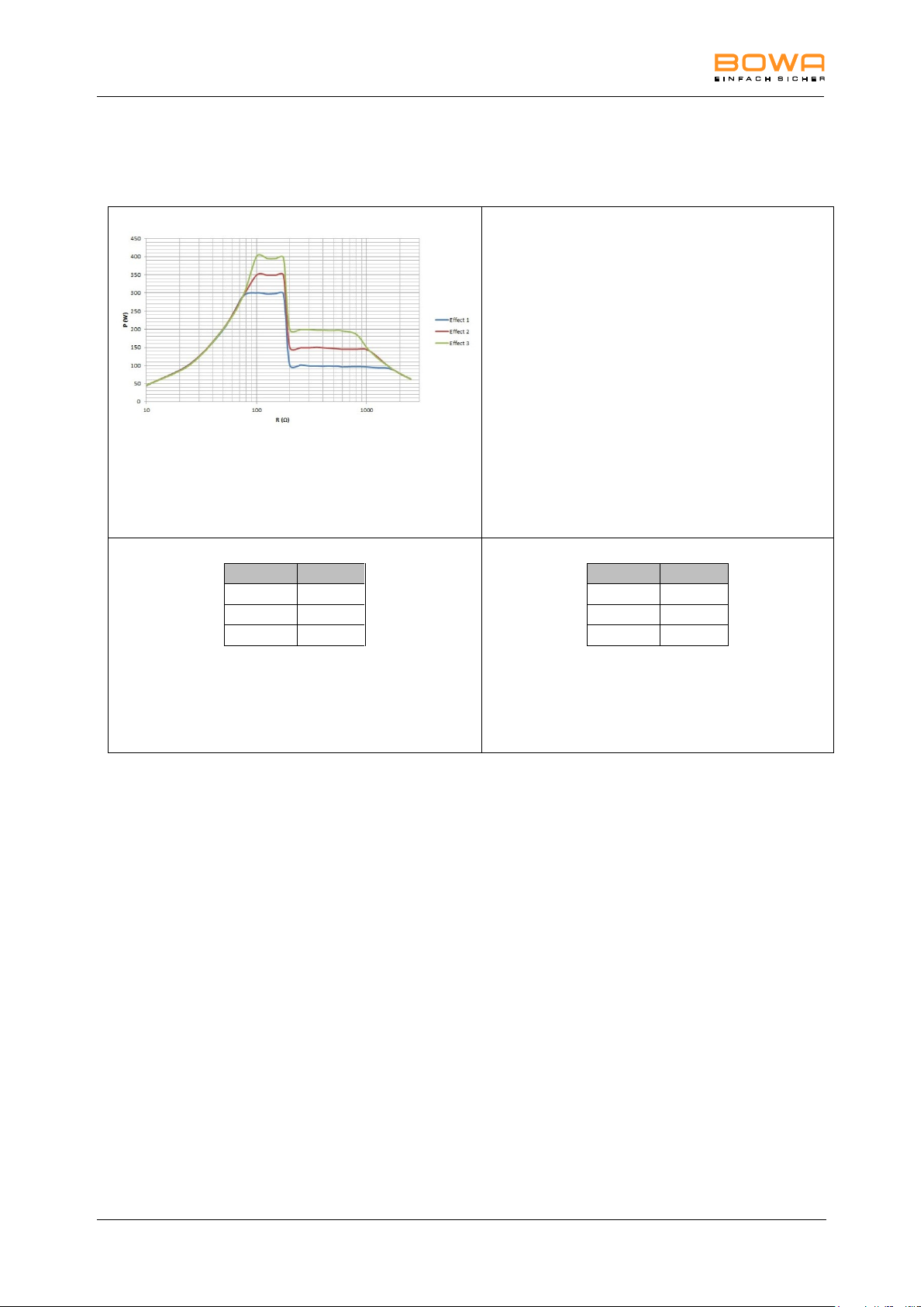
10 Technical specifications
Measurement at ohmic resistances
Diagram of power output P [W] as a
function of the load resistance R [] for
the setting "Monopolar Cutting
MetraLOOP"
Effect
P (W)
1
100
2
150 3 200
Table of power output P [W] as a function
of the setting "Monopolar Cutting
MetraLOOP"
Rated load resistance= 500
Effect
U (Vp)
1
650
2
650 3 650
Table of HF output voltage U [Vp] as a
function of the setting "Monopolar
Cutting MetraLOOP" (idle mode)
Monopolar Cutting – MetraLOOP
86 Operating Manual ARC 350 900-351_IFU_V2.0.0_20221-S0-20150520-EN
Page 87
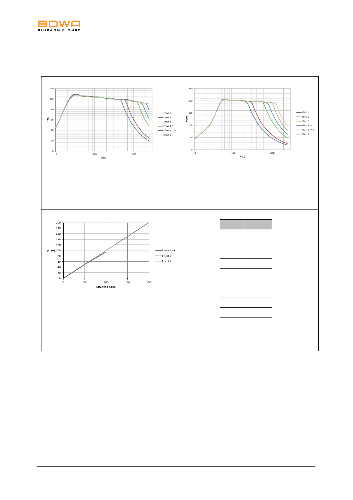
10 Technical specifications
Measurement at ohmic resistances
Diagram of power output P [W] as a
function of the load resistance R [] for
the setting "Monopolar Cutting
Laparoscopy"
= 100 W
Measurement at ohmic resistances
Diagram of power output P [W] as a
function of the load resistance R [] for
the setting "Monopolar Cutting
Laparoscopy"
= 200 W
Diagram of power output P [W] as a
function of the setting "Monopolar
Cutting Laparoscopy"
Rated load resistance= 500
Effect
U (Vp)
1
400
2
450
3
560
4
650
5
650
6
700
7
700
8
700
9
750
Table of HF output voltage U [Vp] as a
function of the setting "Monopolar
Cutting Laparoscopy" (idle mode)
Monopolar Cutting – Laparoscopy
900-351_IFU_V2.0.0_20221-S0-20150520-EN Operating Manual ARC 350 87
Page 88
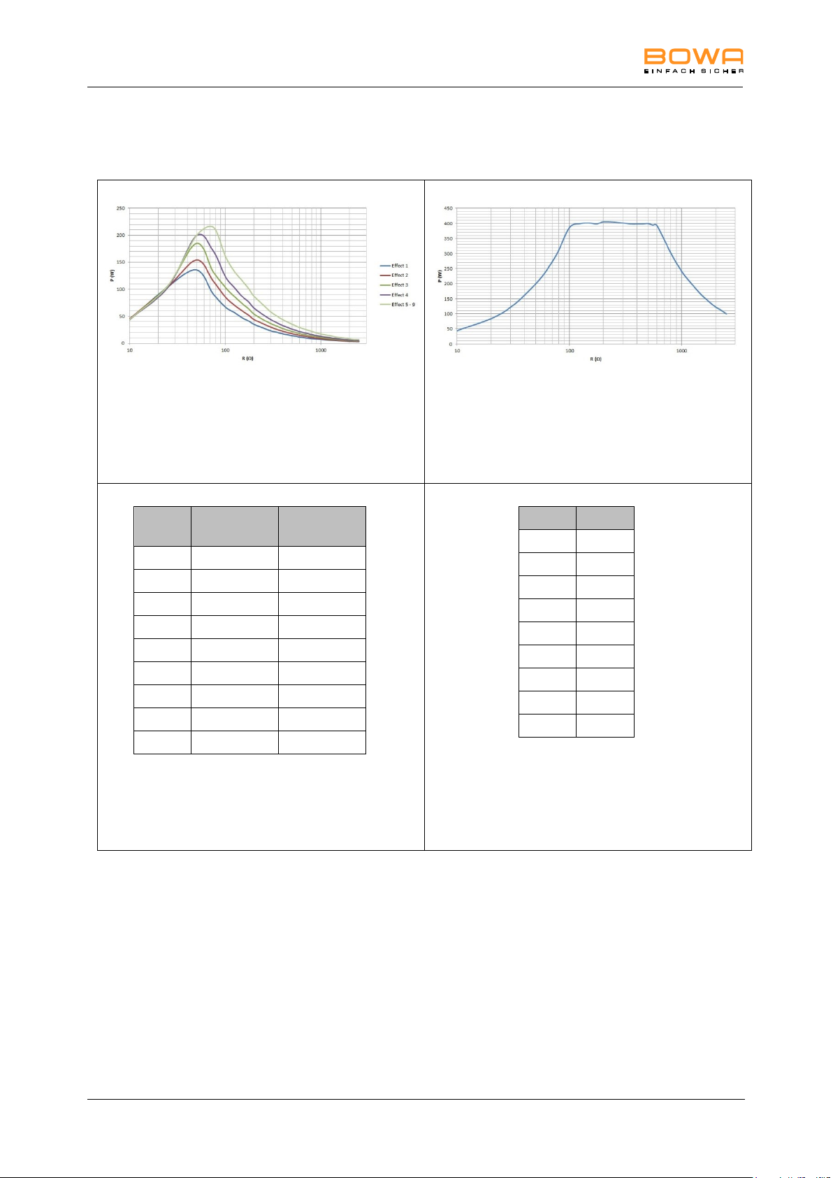
10 Technical specifications
Measurement at ohmic resistances
Diagram of power output P [W] as a
function of the load resistance R [] for
the setting "Monopolar Cutting
GastroLOOP 1"
coag phase
Measurement at ohmic resistances
Diagram of power output P [W] as a
function of the load resistance R [] for
the setting "Monopolar Cutting
GastroLOOP 1"
cut phase
Effect
P (W)
coag phase
P (W)
cut phase
1
14
400
2
18
400
3
22
400
4
26
400
5
35
400
6
35
400
7
35
400
8
35
400
9
35
400
Table of power output P [W] as a
function of the setting "Monopolar
Cutting GastroLOOP 1"
Rated load resistance= 500
Effect
U (Vp)
1
750
2
750
3
750
4
750
5
750
6
750
7
750
8
750
9
750
Table of HF output voltage U [Vp] as a
function of the setting "Monopolar
Cutting GastroLOOP 1"
(idle mode)
Monopolar Cutting – GastroLOOP 1
88 Operating Manual ARC 350 900-351_IFU_V2.0.0_20221-S0-20150520-EN
Page 89
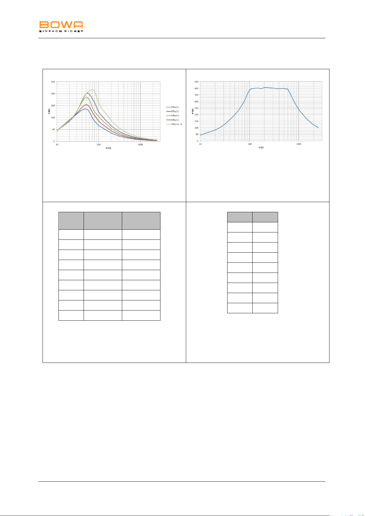
10 Technical specifications
Measurement at ohmic resistances
Diagram of power output P [W] as a
function of the load resistance R [] for
the setting "Monopolar Cutting
GastroLOOP 2"
coag phase
Measurement at ohmic resistances
Diagram of power output P [W] as a
function of the load resistance R [] for
the setting "Monopolar Cutting
GastroLOOP 2"
cut phase
Effect
P (W)
coag phase
P (W)
cut phase
1
14
400
2
18
400
3
22
400
4
26
400
5
35
400
6
35
400
7
35
400
8
35
400
9
35
400
Table of power output P [W] as a
function of the setting "Monopolar
Cutting GastroLOOP 2"
Rated load resistance= 500
Effect
U (Vp)
1
750
2
750
3
750
4
750
5
750
6
750
7
750
8
750
9
750
Table of HF output voltage U [Vp] as a
function of the setting "Monopolar
Cutting GastroLOOP 2"
(idle mode)
Monopolar Cutting – GastroLOOP 2
900-351_IFU_V2.0.0_20221-S0-20150520-EN Operating Manual ARC 350 89
Page 90
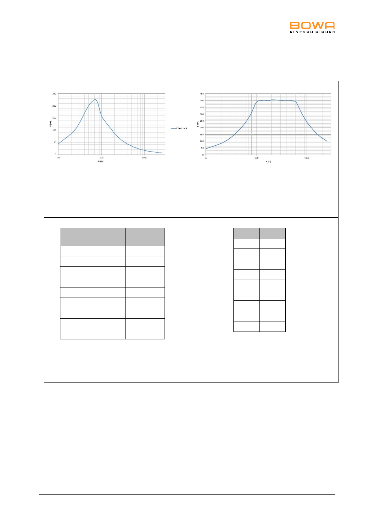
10 Technical specifications
Measurement at ohmic resistances
Diagram of power output P [W] as a
function of the load resistance R [] for
the setting "Monopolar Cutting
GastroLOOP 3"
coag phase
Measurement at ohmic resistances
Diagram of power output P [W] as a
function of the load resistance R [] for
the setting "Monopolar Cutting
GastroLOOP 3"
cut phase
Effect
P (W)
coag phase
P (W)
cut phase
1
35
400
2
35
400
3
35
400
4
35
400
5
35
400
6
35
400
7
35
400
8
35
400
9
35
400
Table of power output P [W] as a
function of the setting "Monopolar
Cutting GastroLOOP 3"
Rated load resistance= 500
Effect
U (Vp)
1
750
2
750
3
750
4
750
5
750
6
750
7
750
8
750
9
750
Table of HF output voltage U [Vp] as a
function of the setting "Monopolar
Cutting GastroLOOP 3"
(idle mode)
Monopolar Cutting – GastroLOOP 3
90 Operating Manual ARC 350 900-351_IFU_V2.0.0_20221-S0-20150520-EN
Page 91
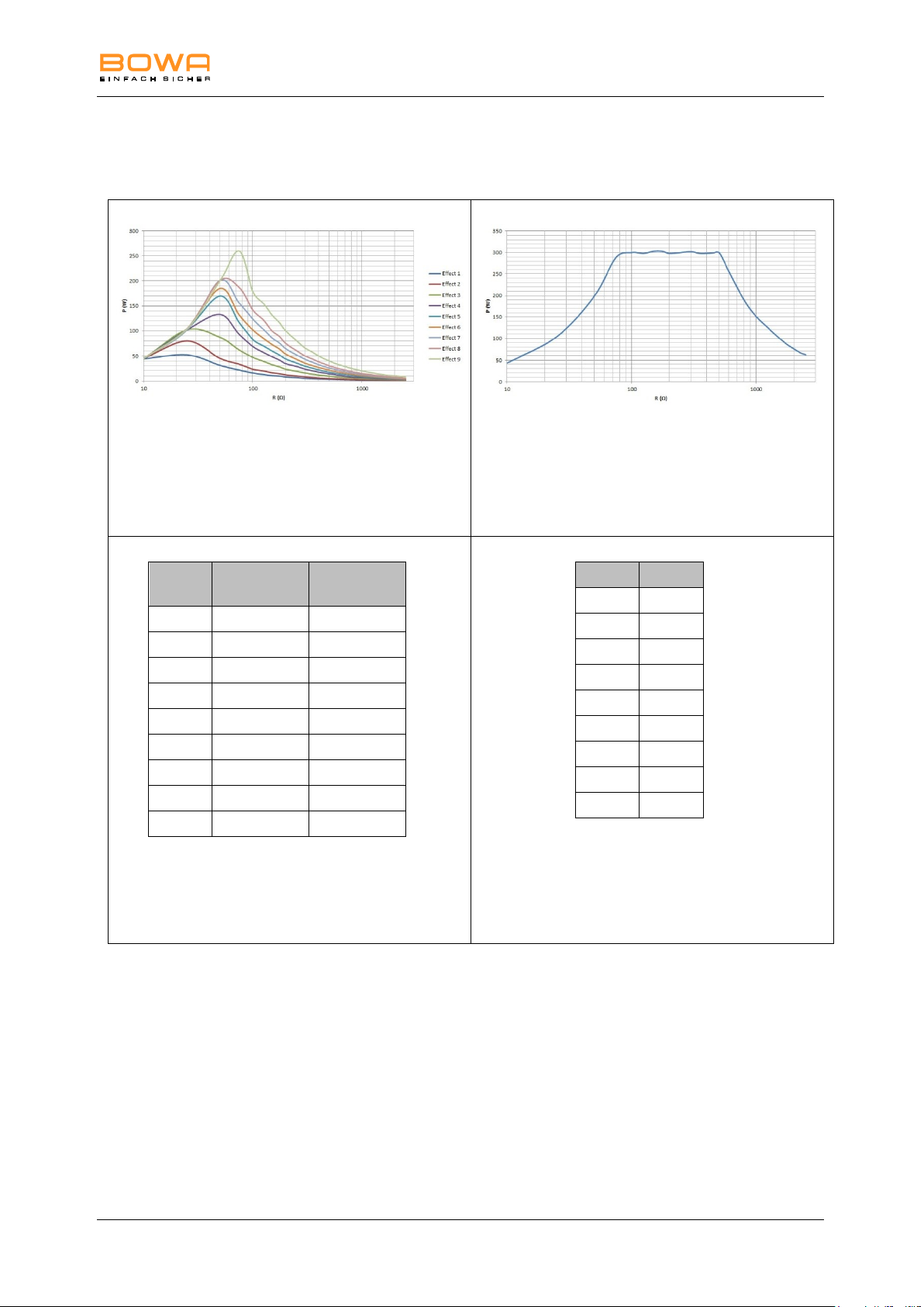
10 Technical specifications
Measurement at ohmic resistances
Diagram of power output P [W] as a
function of the load resistance R [] for
the setting "Monopolar Cutting
GastroKNIFE 1"
coag phase
Measurement at ohmic resistances
Diagram of power output P [W] as a
function of the load resistance R [] for
the setting "Monopolar Cutting
GastroKNIFE 1"
cut phase
Effect
P (W)
coag phase
P (W)
cut phase
1 3 300
2 5 300
3 9 300
4
14
300
5
17
300
6
22
300
7
26
300
8
30
300
9
40
300
Table of power output P [W] as a
function of the setting "Monopolar
Cutting GastroKNIFE 1"
Rated load resistance= 500
Effect
U (Vp)
1
650
2
650
3
650
4
650
5
650
6
650
7
650
8
650
9
650
Table of HF output voltage U [Vp] as a
function of the setting "Monopolar
Cutting GastroKNIFE 1"
(idle mode)
Monopolar Cutting – GastroKNIFE 1
900-351_IFU_V2.0.0_20221-S0-20150520-EN Operating Manual ARC 350 91
Page 92
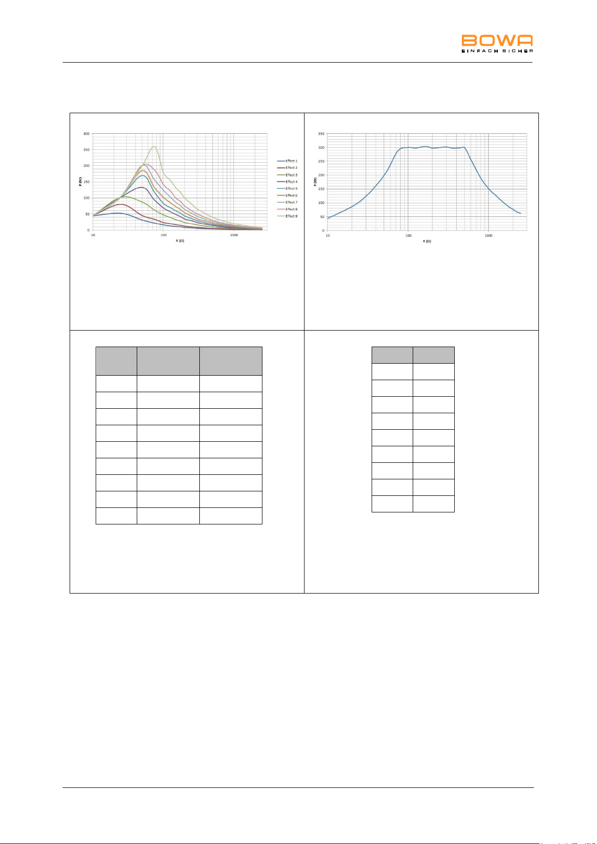
10 Technical specifications
Measurement at ohmic resistances
Diagram of power output P [W] as a
function of the load resistance R [] for
the setting "Monopolar Cutting
GastroKNIFE 2
coag phase
Measurement at ohmic resistances
Diagram of power output P [W] as a
function of the load resistance R [] for
the setting "Monopolar Cutting
GastroKNIFE 2"
cut phase
Effect
P (W)
coag phase
P (W)
cut phase
1 3 300
2 5 300
3 9 300
4
14
300
5
17
300
6
22
300
7
26
300
8
30
300
9
40
300
Table of power output P [W] as a
function of the setting "Monopolar
Cutting GastroKNIFE 2"
Rated load resistance= 500
Effect
U (Vp)
1
650
2
650
3
650
4
650
5
650
6
650
7
650
8
650
9
650
Table of HF output voltage U [Vp] as a
function of the setting "Monopolar
Cutting GastroKNIFE 2"
(idle mode)
Monopolar Cutting – GastroKNIFE 2
92 Operating Manual ARC 350 900-351_IFU_V2.0.0_20221-S0-20150520-EN
Page 93
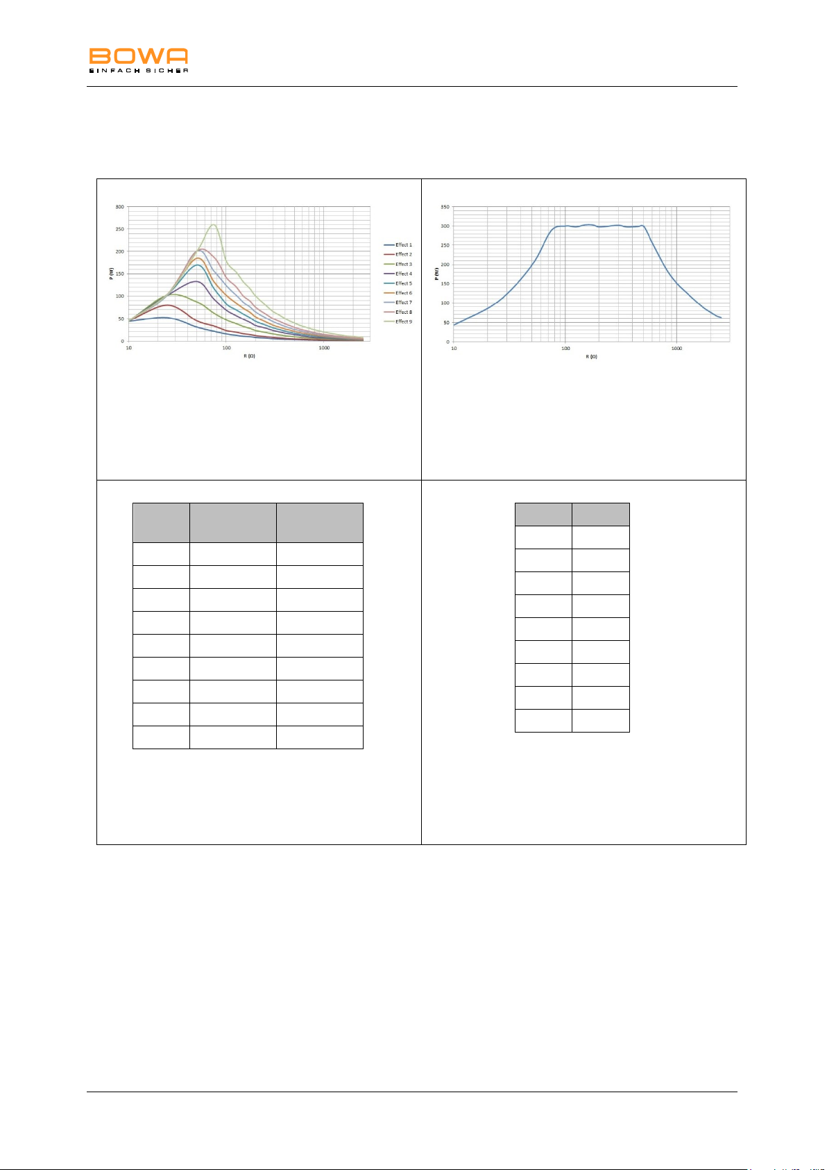
10 Technical specifications
Measurement at ohmic resistances
Diagram of power output P [W] as a
function of the load resistance R [] for
the setting "Monopolar Cutting
GastroKNIFE 3"
coag phase
Measurement at ohmic resistances
Diagram of power output P [W] as a
function of the load resistance R [] for
the setting "Monopolar Cutting
GastroKNIFE 3"
cut phase
Effect
P (W)
coag phase
P (W)
cut phase
1 3 300
2 5 300
3 9 300
4
14
300
5
17
300
6
22
300
7
26
300
8
30
300
9
40
300
Table of power output P [W] as a
function of the setting "Monopolar
Cutting GastroKNIFE 3"
Rated load resistance= 500
Effect
U (Vp)
1
650
2
650
3
650
4
650
5
650
6
650
7
650
8
650
9
650
Table of HF output voltage U [Vp] as a
function of the setting "Monopolar
Cutting GastroKNIFE 3"
(idle mode)
Monopolar Cutting – GastroKNIFE 3
900-351_IFU_V2.0.0_20221-S0-20150520-EN Operating Manual ARC 350 93
Page 94
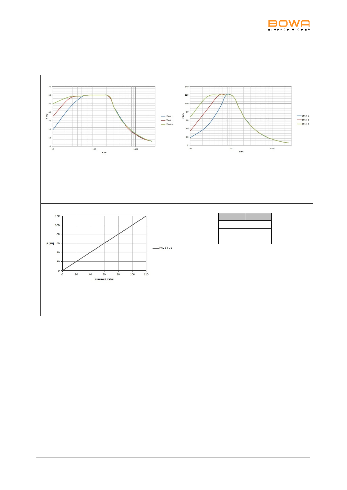
10 Technical specifications
Measurement at ohmic resistances
Diagram of power output P [W] as a
function of the load resistance R [] for
the setting "Monopolar Coagulation
Moderate"
= 60 W
Measurement at ohmic resistances
Diagram of power output P [W] as a
function of the load resistance R [] for
the setting "Monopolar Coagulation
Moderate"
= 120 W
Diagram of power output P [W] as a
function of the setting "Monopolar
Coagulation Moderate"
Rated load resistance= 75
Effect
U (Vp)
1
250 2 250
3
250
Table of HF output voltage U [Vp] as a
function of the setting "Monopolar
Coagulation Moderate"
(idle mode)
Monopolar Coagulation – Moderate
94 Operating Manual ARC 350 900-351_IFU_V2.0.0_20221-S0-20150520-EN
Page 95
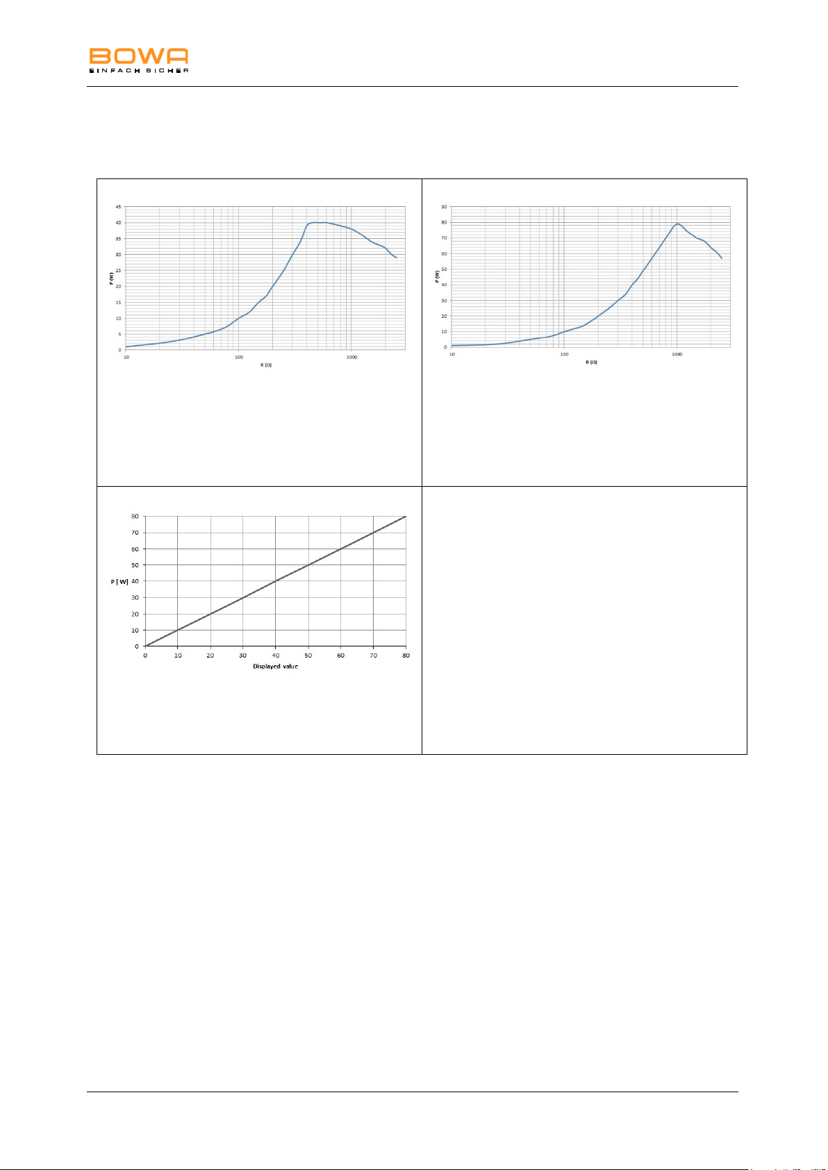
10 Technical specifications
Measurement at ohmic resistances
Diagram of power output P [W] as a
function of the load resistance R [] for
the setting "Monopolar Coagulation
Forced non cutting"
= 40 W
Measurement at ohmic resistances
Diagram of power output P [W] as a
function of the load resistance R [] for
the setting "Monopolar Coagulation
Forced non cutting"
= 80 W
Diagram of power output P [W] as a
function of the setting "Monopolar
Coagulation Forced non cutting"
Rated load resistance = 1000
HF output voltage U [Vp] for the setting
"Monopolar Coagulation Moderate"
(idle mode)
= 3500 Vp
Monopolar Coagulation – Forced non cutting
900-351_IFU_V2.0.0_20221-S0-20150520-EN Operating Manual ARC 350 95
Page 96
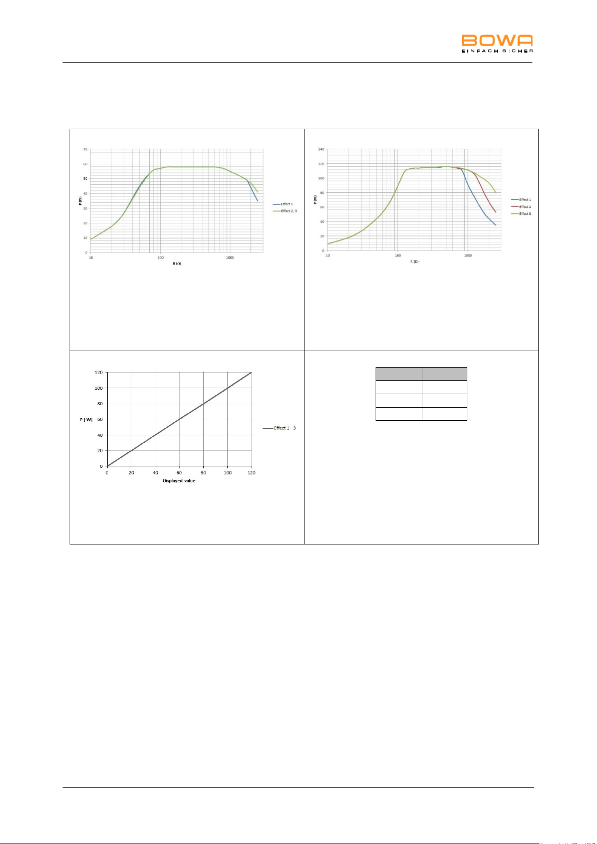
10 Technical specifications
Measurement at ohmic resistances
Diagram of power output P [W] as a
function of the load resistance R [] for
the setting "Monopolar Coagulation
Forced mixed"
= 60 W
Measurement at ohmic resistances
Diagram of power output P [W] as a
function of the load resistance R [] for
the setting "Monopolar Coagulation
Forced mixed"
= 120 W
Diagram of power output P [W] as a
function of the setting "Monopolar
Coagulation Forced mixed"
Rated load resistance = 500
Effect
U (Vp)
1
2300
2
2500
3
2800
Table of HF output voltage U [Vp] as a
function of the setting "Monopolar
Coagulation Forced mixed"
(idle mode)
Monopolar Coagulation – Forced mixed
96 Operating Manual ARC 350 900-351_IFU_V2.0.0_20221-S0-20150520-EN
Page 97
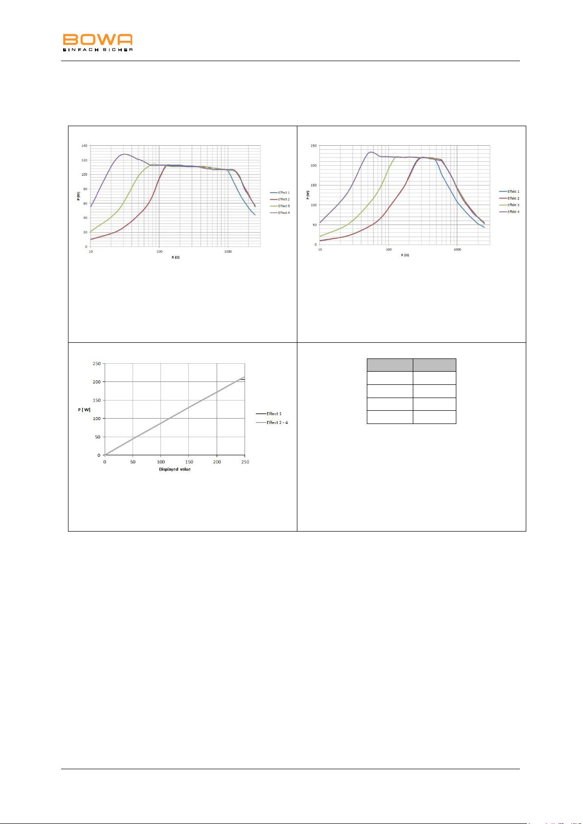
10 Technical specifications
Measurement at ohmic resistances
Diagram of power output P [W] as a
function of the load resistance R [] for
the setting "Monopolar Coagulation
Forced cutting"
= 125 W
Measurement at ohmic resistances
Diagram of power output P [W] as a
function of the load resistance R [] for
the setting "Monopolar Coagulation
Forced cutting"
= 250 W
Diagram of power output P [W] as a
function of the setting "Monopolar
Coagulation Forced cutting"
Rated load resistance = 500
Effect
U (Vp)
1
1500
2
1500
3
1300
4
1300
Table of HF output voltage U [Vp] as a
function of the setting "Monopolar
Coagulation Forced cutting"
(idle mode)
Monopolar Coagulation – Forced cutting
900-351_IFU_V2.0.0_20221-S0-20150520-EN Operating Manual ARC 350 97
Page 98
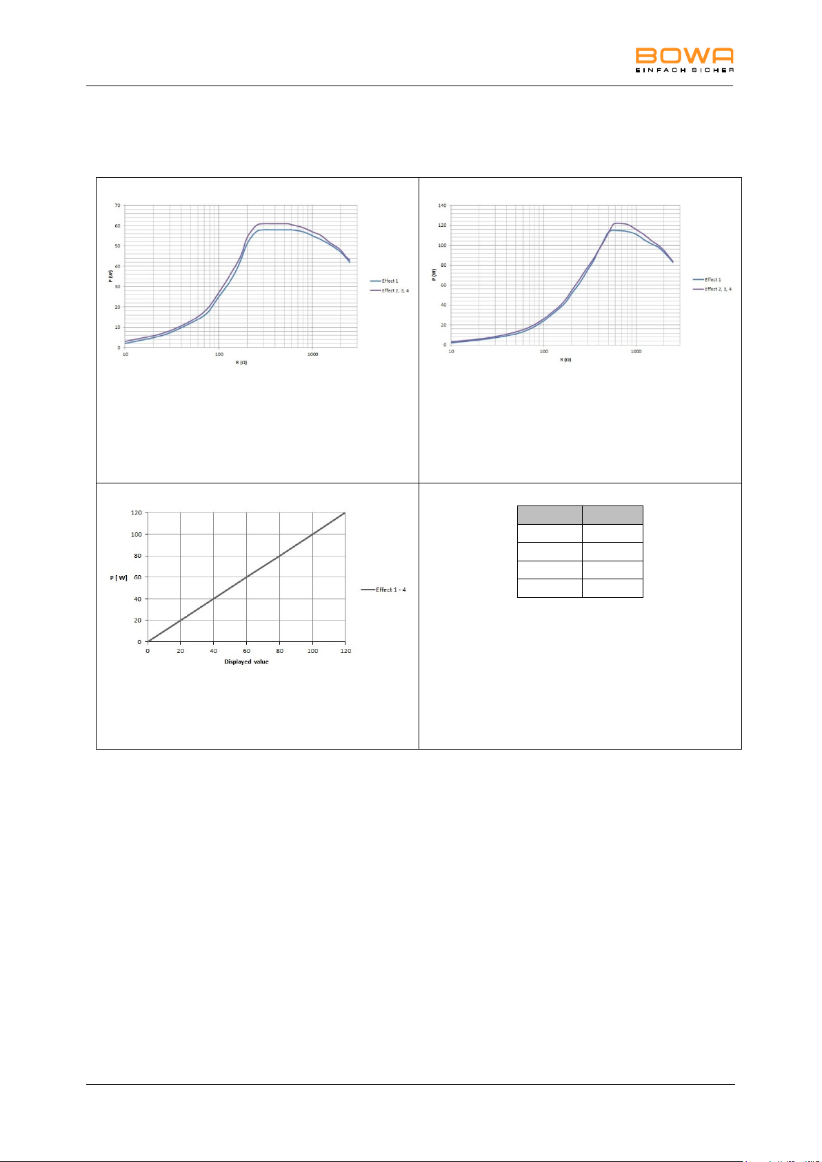
10 Technical specifications
Measurement at ohmic resistances
Diagram of power output P [W] as a
function of the load resistance R [] for
the setting "Monopolar Coagulation
Spray"
= 60 W
Measurement at ohmic resistances
Diagram of power output P [W] as a
function of the load resistance R [] for
the setting "Monopolar Coagulation
Spray"
= 120 W
Diagram of power output P [W] as a
function of the setting "Monopolar
Coagulation Spray"
Rated load resistance = 500
Effect
U (Vp)
1
3000
2
3800
3
4600
4
5000
Table of HF output voltage U [Vp] as a
function of the setting "Monopolar
Coagulation Spray" (idle mode)
Monopolar Coagulation – Spray
98 Operating Manual ARC 350 900-351_IFU_V2.0.0_20221-S0-20150520-EN
Page 99
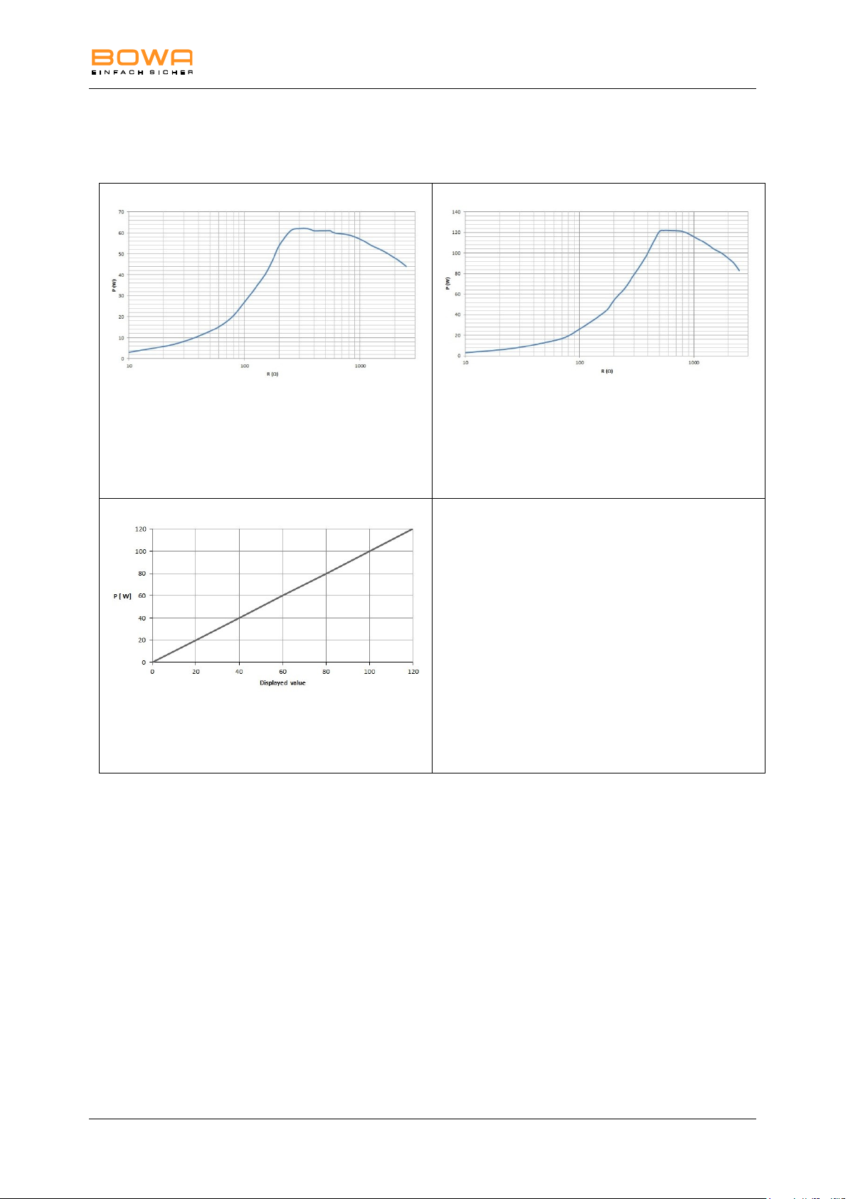
10 Technical specifications
Measurement at ohmic resistances
Diagram of power output P [W] as a
function of the load resistance R [] for
the setting "Monopolar Coagulation
Argon open"
= 60 W
Measurement at ohmic resistances
Diagram of power output P [W] as a
function of the load resistance R [] for
the setting "Monopolar Coagulation
Argon open"
= 120 W
Diagram of power output P [W] as a
function of the setting "Monopolar
Coagulation Argon open"
Rated load resistance = 500
HF output voltage U [Vp] for the setting
"Monopolar Coagulation Argon open"
(idle mode)
= 4600 Vp
Monopolar Coagulation – Argon open
900-351_IFU_V2.0.0_20221-S0-20150520-EN Operating Manual ARC 350 99
Page 100
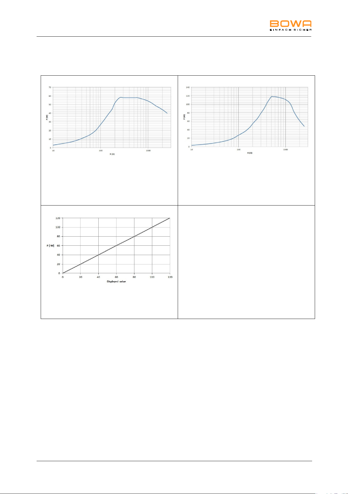
10 Technical specifications
Measurement at ohmic resistances
Diagram of power output P [W] as a
function of the load resistance R [] for
the setting "Monopolar Coagulation
Argon flexible"
= 60 W
Measurement at ohmic resistances
Diagram of power output P [W] as a
function of the load resistance R [] for
the setting "Monopolar Coagulation
Argon flexible"
= 120 W
Diagram of power output P [W] as a
function of the setting "Monopolar
Coagulation Argon flexible"
Rated load resistance = 500
HF output voltage U [Vp] for the setting
"Monopolar Coagulation Argon flexible"
(idle mode)
= 4400 Vp
Monopolar Coagulation – Argon flexible
100 Operating Manual ARC 350 900-351_IFU_V2.0.0_20221-S0-20150520-EN
 Loading...