

Page 1
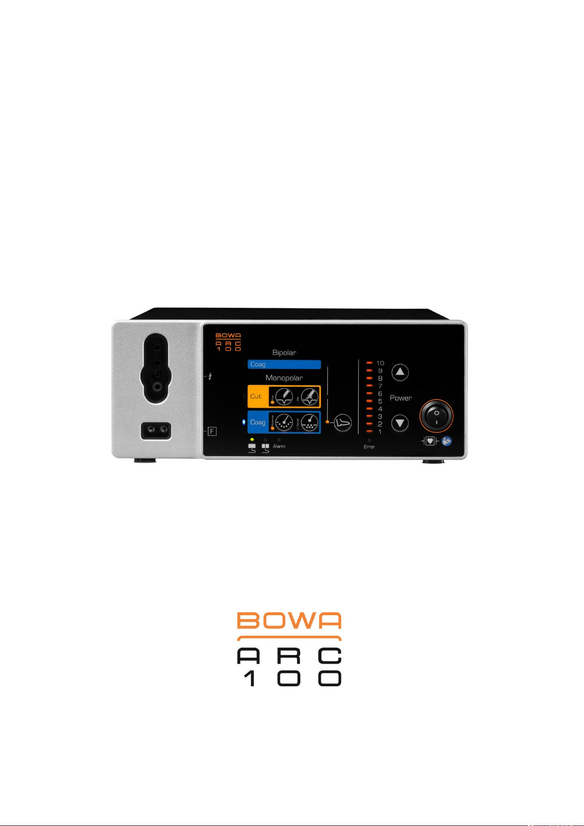
OPERATING MANUAL
ELECTROSURGICAL UNIT
Page 2

Page 3

900-100_IFU-V1.0_11587-S0-20141209-EN ARC 100 Operating Manual 3
Page 4
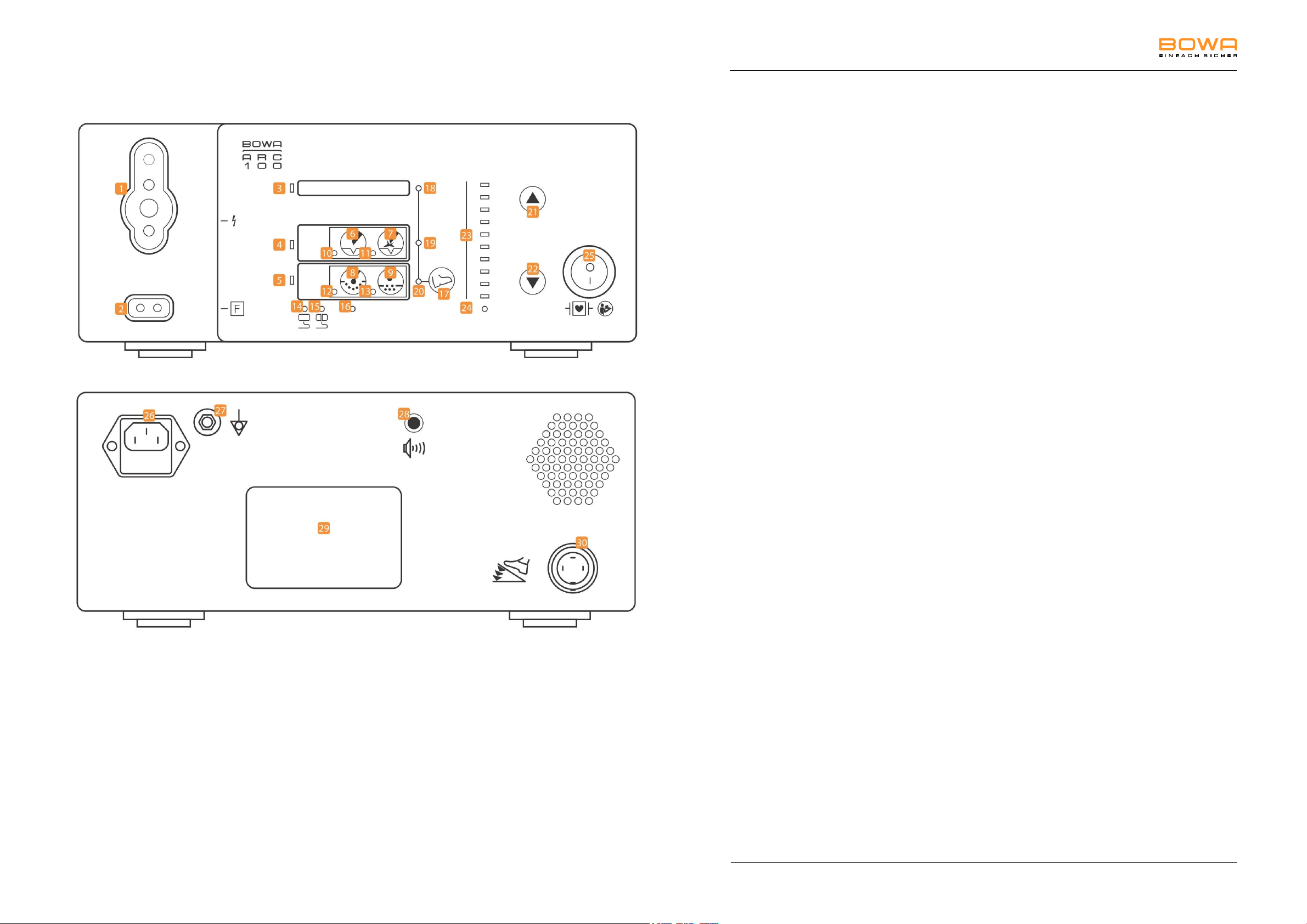
Legend
Front of ARC 100
1
Multifunction connection socket for monopolar instruments
with hand or foot switch or bipolar instruments with foot
switch *
2
Socket for the neutral electrode (NE) *
3
Activation indicator for bipolar coagulation (blue)
4
Activation indicator for monopolar cutting (yellow)
5
Activation indicator for monopolar coagulation (blue)
6
Key for "Pure" monopolar cutting current
7
Key for "Dry" monopolar cutting current
8
Key for "Moderate" monopolar coagulation current
9
Key for "Forced" monopolar coagulation current
10
Indicator for "Pure" monopolar cutting current
11
Indicator for "Dry" monopolar cutting current
12
Indicator for "Moderate" monopolar coagulation current
13
Indicator for "Forced" monopolar coagulation current
14
Neutral electrode monitoring, non-split
15
EASY neutral electrode monitoring, split
16
Indicator for EASY neutral electrode "Alarm" fault status
17
Key for foot switch assignment
18
Indicator for foot switched bipolar coagulation
19
Indicator for foot switched monopolar cutting
20
Indicator for foot switched monopolar coagulation
21/22
Keys for adjusting the power limitation
23
Power limitation indicator
24
Indicator for "Error" fault status
25
On/off switch
Rear of ARC 100
26
IEC chassis-mount power connector
27
Connection for equipotential bonding
28
Knob to adjust volume
29
Rating label
30
Connection socket for foot switch
*
Applied part of Type F according to IEC 60601-1
Legend
4 ARC 100 Operating Manual 900-100_IFU-V1.0_11587-S0-20141209-EN
Page 5

Table of contents
Table of contents
Legend ......................................................................................................................................................... 4
1. Using this operating manual ........................................................................................................... 8
1.1. Revision index ..................................................................................................................... 8
1.2. Scope of validity .................................................................................................................. 8
1.3. Other applicable documents ............................................................................................... 8
1.4. Symbols and notation ......................................................................................................... 9
1.4.1. Structure of warning instructions ......................................................................... 9
1.4.2. Hazard levels of warning instructions .................................................................. 9
1.4.3. Tips ...................................................................................................................... 9
1.4.4. Other symbols and notation............................................................................... 10
2. Safety ............................................................................................................................................... 11
2.1. Intended use ..................................................................................................................... 11
2.2. General safety instructions ............................................................................................... 12
2.3. Personal safety instructions .............................................................................................. 13
2.3.1. Ambient conditions ............................................................................................ 13
2.3.2. Patients with pacemakers.................................................................................. 13
2.3.3. Safe positioning of the patient ........................................................................... 14
2.3.4. Correct connection of the HF device ................................................................. 14
2.3.5. Correct use of the HF device ............................................................................. 14
2.3.6. Adjusting the settings of the HF device and use of the accessories ................. 15
2.4. Device-related safety instructions ..................................................................................... 16
2.5. Safe handling (general instructions) ................................................................................. 16
2.5.1. Surgical environment: Prevention of explosions and ignition ............................ 17
2.5.2. Application of the neutral electrode ................................................................... 17
3. Functionality ................................................................................................................................... 20
3.1. Monopolar modes ............................................................................................................. 20
3.2. Bipolar mode ..................................................................................................................... 20
3.3. Monopolar/bipolar multifunction socket ............................................................................ 21
3.4. Connection socket for neutral electrode ........................................................................... 21
3.5. Activation and alarm signals in monopolar and bipolar mode .......................................... 21
3.6. Emergency stop ................................................................................................................ 22
3.7. Monitoring functions .......................................................................................................... 22
3.7.1. Self-test.............................................................................................................. 22
900-100_IFU-V1.0_11587-S0-20141209-EN ARC 100 Operating Manual 5
Page 6

Table of contents
3.7.2. Cyclical test during operation ............................................................................ 22
3.8. Neutral electrode monitoring ............................................................................................. 22
3.8.1. General information ........................................................................................... 22
3.8.2. EASY neutral electrode monitoring (EASY monitoring) .................................... 23
3.9. Foot switches .................................................................................................................... 23
4. Description ...................................................................................................................................... 24
4.1. Symbols on the device ...................................................................................................... 24
4.1.1. Rating label ........................................................................................................ 24
4.2. Scope of delivery .............................................................................................................. 25
4.3. Components required for operation .................................................................................. 25
4.4. Operating conditions ......................................................................................................... 25
5. Preparation...................................................................................................................................... 26
5.1. Setting up the HF device................................................................................................... 26
5.2. Switching on the HF device .............................................................................................. 27
5.3. Connecting instruments .................................................................................................... 27
5.3.1. Instruments for monopolar applications ............................................................ 27
5.3.2. Instruments for bipolar applications ................................................................... 27
5.3.3. Connecting the foot switch ................................................................................ 28
5.3.4. Assigning a foot switch output ........................................................................... 28
5.4. Functional test ................................................................................................................... 28
5.4.1. Autotest function ................................................................................................ 28
5.4.2. Functional test execution ................................................................................... 28
5.4.3. Actions in case of problems............................................................................... 29
5.4.4. EASY neutral electrode monitoring (EASY monitoring) ................................... 29
6. Operation......................................................................................................................................... 30
6.1. Mode overview .................................................................................................................. 30
6.2. Basic settings .................................................................................................................... 31
6.2.1. Selecting the mode ............................................................................................ 31
6.2.2. Setting power levels .......................................................................................... 31
6.2.3. Changing the volume ......................................................................................... 31
6.3. Mode descriptions ............................................................................................................. 31
6.3.1. Monopolar cutting, "Pure" .................................................................................. 31
6.3.2. Monopolar cutting, "Dry" .................................................................................... 31
6.3.3. Monopolar coagulation, "Moderate" .................................................................. 32
6.3.4. Monopolar coagulation, "Forced" ...................................................................... 32
6 ARC 100 Operating Manual 900-100_IFU-V1.0_11587-S0-20141209-EN
Page 7

Table of contents
6.3.5. Bipolar coagulation ............................................................................................ 32
7. Detecting and correcting faults .................................................................................................... 33
7.1. System errors .................................................................................................................... 33
7.1.1. Error list ............................................................................................................. 33
7.2. Fault indications for EASY monitoring .............................................................................. 34
8. Cleaning .......................................................................................................................................... 35
8.1. Preparation of the accessories ......................................................................................... 35
8.2. Disinfection and cleaning .................................................................................................. 35
9. Maintenance and repair ................................................................................................................. 36
9.1. Maintenance ..................................................................................................................... 36
9.1.1. Safety inspection ............................................................................................... 36
9.2. Repairs .............................................................................................................................. 37
9.3. Technical service .............................................................................................................. 38
10. Storage ............................................................................................................................................ 38
11. Technical specifications ................................................................................................................ 39
11.1. Technical data for ARC 100 .............................................................................................. 39
11.2. Power, voltage and current charts .................................................................................... 42
12. Accessories and replacement parts ............................................................................................. 47
13. EMC .................................................................................................................................................. 47
13.1. Guidelines and manufacturer's declaration in accordance with DIN EN 60601-
1-2, para. 6.8.3.201 ........................................................................................................... 47
14. Disposal ........................................................................................................................................... 51
900-100_IFU-V1.0_11587-S0-20141209-EN ARC 100 Operating Manual 7
Page 8

1 Using this operating manual
Software version
Last revised
1.0
2014/12
1. Using this operating manual
This operating manual is part of the product.
BOWA-electronic GmbH & Co. KG, referred to in the following simply as
BOWA, assume no liability nor provide any warranty whatsoever for any
damage or consequential damages arising from non-compliance with
the operating manual.
Read the operating manual carefully and thoroughly before using
this device.
Store the operating manual in a safe place throughout the service
life of the device.
Keep the operating manual accessible to operating theatre
personnel.
Give the operating manual to each successive owner and/or user
of this device.
Always update the operating manual whenever you receive
additional information from the manufacturer.
-Index @ 7\mod_1308730384316_258.doc @ 52335 @ 2
1.1. Revision index
Pos: 5 /679-BOWA/HF-Geräte/ARC 3 00/350/1 Umga ng mit/Gültigkeit @ 4\mod_1261 040280413_2 58.doc @ 34386 @ 2
1.2. Scope of validity
This operating manual applies only to the devices designated on the title
page.
1.3. Other applicable documents
Comply with other applicable documents mentioned in the
appendix or in the other sections.
Provided in addition to this operating manual is an introductory
video; see accompanying CD.
8 ARC 100 Operating Manual 900-100_IFU-V1.0_11587-S0-20141209-EN
Page 9
1 Using this operating manual
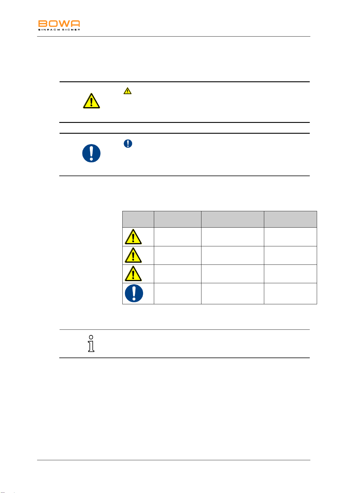
SIGNAL WORD
Type, source and consequences of the risk (personal injury)!
Measure for avoiding the risk.
NOTE
Type, source and consequences of the risk (property damage)!
Measure.
Symbol
Hazard level
Probability of
occurrence
Consequences of
non-compliance
DANGER
Immediate risk
Death or serious
injuries
WARNING
Possible risk
Death or serious
injuries
CAUTION
Possible risk
Minor injuries
NOTE
Possible risk
Property damage
Tips and additional information for easier working.
1.4. Symbols and notation
1.4.1. Structure of warning instructions
1.4.2. Hazard levels of warning instructions
1.4.3. Tips
900-100_IFU-V1.0_11587-S0-20141209-EN ARC 100 Operating Manual 9
Page 10
1 Using this operating manual
Symbol or notation
Meaning
Prerequisite for an activity
Activity with one step
1.
2.
3.
Activity with several steps in strict
sequence
Result of preceding activity
List (first level)
List (second level)
Emphasis
Emphasis
...; see Section xxx, page xxx
Cross reference
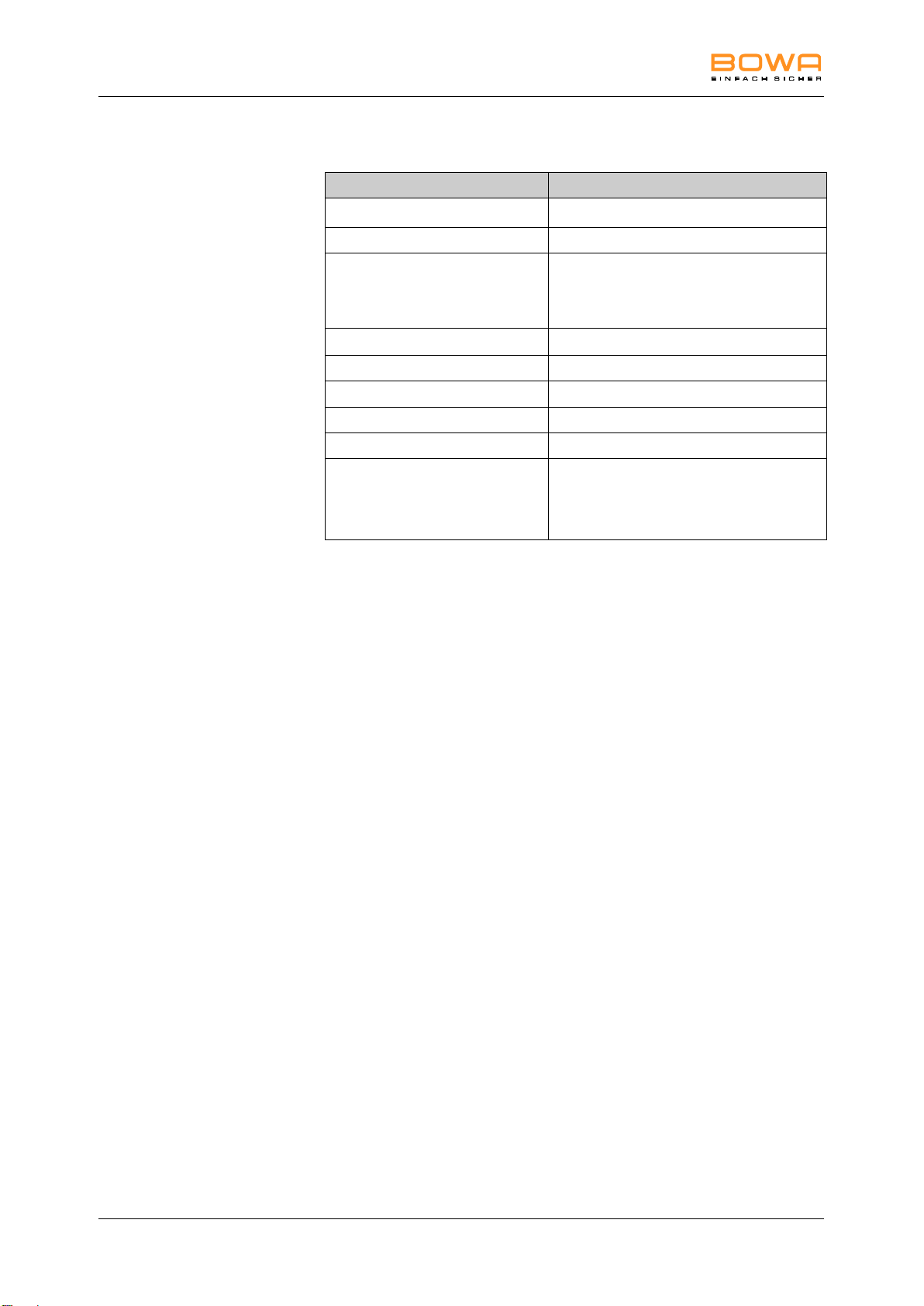
... "On/off switch" 25
Bolded numbers (here: 25) refer to a
schematic diagram of the ARC 100 and the
respective legend
(page 4)
1.4.4. Other symbols and notation
10 ARC 100 Operating Manual 900-100_IFU-V1.0_11587-S0-20141209-EN
Page 11

2 Safety
BOWA requires that the HF device is operated under the supervision of
qualified and authorized personnel. The surgeon and medical staff must
be trained in the fundamental principles, rules for use and risks of HF
surgery and must be familiar with these in order to safely and reliably
prevent putting patients, staff and equipment at risk.
Any other use is neither intended nor proper and must be effectively
prevented.
2. Safety
2.1. Intended use
The HF device is intended exclusively for the generation of electrical
power for monopolar cutting or monopolar and bipolar coagulation in
surgical operations.
It is used in the following areas:
General surgery
Paediatric surgery
Gynaecology
Hand surgery
Neurosurgery (not on the central nervous system)
Dermatology
Plastic surgery
Oral and maxillofacial surgery
Dentistry
ENT
Do not use the HF device if, in the opinion of an experienced physician
or according to current professional literature, such use would endanger
the patient, due for example to the general condition of the patient, or if
other contraindications are present.
900-100_IFU-V1.0_11587-S0-20141209-EN ARC 100 Operating Manual 11
Page 12

2 Safety
To protect personnel, BOWA recommends the use of a smoke evacuator
to extract electrosurgical smoke, e.g. BOWA SHE SHA.
2.2. General safety instructions
Ensure that no electronic devices that are subject to interference
from electromagnetic fields are set up in the vicinity of the HF
device.
Please comply with the instructions on electromagnetic
compatibility (EMC); see Section EMC, page 47.
Always connect the HF device to a mains power system with a
protective earth lead in order to prevent electric shock.
Additional devices that are connected to electrical medical devices must
demonstrably satisfy the relevant IEC or ISO standards (e.g. IEC 60950
for data processing devices). Furthermore, all configurations must
comply with the standardised requirements for medical systems (see
IEC 60601-1-1 or Section 16 of the 3rd edition of IEC 60601-1, as
relevant). Anyone who connects additional devices to medical electrical
devices is perforce a system configurator and therefore responsible for
meeting standardised system requirements. Please note that local laws
prevail over the aforementioned standard requirements. For further
advice, please contact your local specialist retailer or our technical
service; see Section Technical service, page 38.
12 ARC 100 Operating Manual 900-100_IFU-V1.0_11587-S0-20141209-EN
Page 13
2 Safety
2.3. Personal safety instructions
2.3.1. Ambient conditions
Excessive leakage currents may create a risk of burns to the patient.
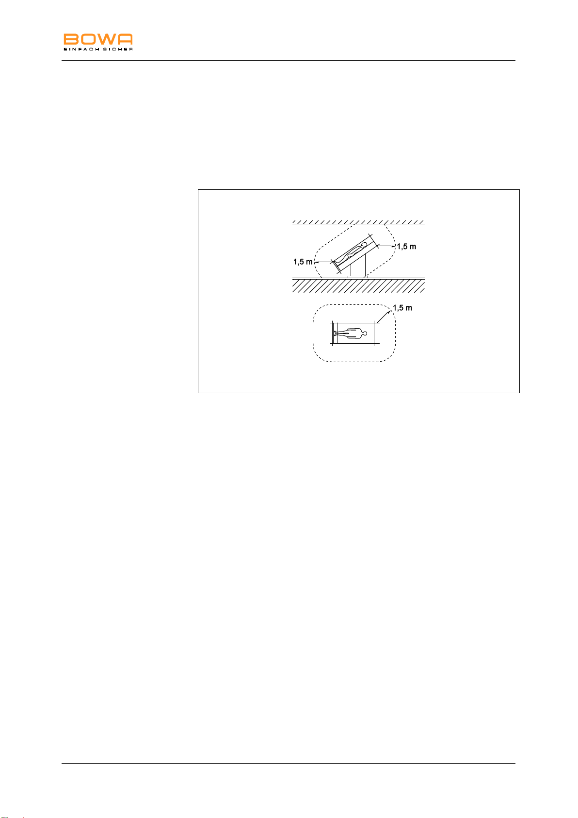
Do not operate the HF device in the immediate vicinity of the
patient. Observe the minimum distances recommended by BOWA,
as shown in the following figure.
2.3.2. Patients with pacemakers
Malfunction or destruction of the pacemaker can endanger the life of the
patient or result in irreversible injuries to the patient.
In cases of patients with pacemakers, consult the cardiologist
before carrying out HF surgery.
Use bipolar HF methods when possible.
Move the HF neutral electrode close to the operating field.
Set the demand pacemaker to a fixed frequency.
Ensure that the pacemaker does not come into contact with the HF
electrode.
Keep a fully operational defibrillator within reach.
Carry out a postoperative pacemaker check.
900-100_IFU-V1.0_11587-S0-20141209-EN ARC 100 Operating Manual 13
Page 14

2 Safety
2.3.3. Safe positioning of the patient
Position the patient so that the patient is not touching any metal
parts that are grounded or have considerable capacitance relative
to ground (e.g. operating table brackets). If necessary, place antistatic towels between the patient and the bedding.
Ensure that the patient does not touch any wet towels or bedding.
Place anti-static towels between areas of heavy sweating and skin-
to-skin contact on the patient's trunk.
Ensure a suitable support surface in order to prevent pressure
necrosis.
Drain urine via the catheter.
2.3.4. Correct connection of the HF device
Always ground the HF device via the equipotential bonding.
Also observe the requirements in Section 8 of ISO 60601-1
regarding medical electrical systems.
Do not use any needle electrodes for monitoring.
Attach electrodes of physiological monitoring devices without
protective resistors or HF regulators as far as possible from the HF
electrodes.
Attach lines from monitoring devices so that they do not lie on the
patient's skin.
Keep the leads to the HF electrodes as short as possible and
position them so that they do not touch the patient or other leads.
Do not place any objects on the HF device.
2.3.5. Correct use of the HF device
Inadvertent activation in the non-visible area of the HF device can injure
the patient.
Activate the HF device only when the electrode is in your field of
vision and you can quickly deactivate the HF device at all times.
After inadvertent activation of the HF device, switch off the device
immediately using the on/off switch.
Pay particular attention whenever you use the foot switch or the
manual switch.
Lack of preparation, errors in usage or faults in the HF device can cause
damage to the HF device.
Use the automatic monitoring functions to ensure that the HF
device works properly without errors. For information on the
automatic test functions, see Section Monitoring functions,
page 22.
Ensure that no conductive fluids (e.g. blood, amniotic fluid) have
penetrated the foot switch or the manual switch.
Ensure that the cables for the foot switch and manual switch are
free from short circuits and broken leads.
14 ARC 100 Operating Manual 900-100_IFU-V1.0_11587-S0-20141209-EN
Page 15

2 Safety
2.3.6. Adjusting the settings of the HF device and use of the
accessories
Setting the output power too high can injure the patient. Therefore,
before you increase the output power, ensure that:
the neutral electrode is correctly positioned,
the working electrodes are clean,
and the plug connections are all correct.
Setting the HF device correctly
To prevent inadvertent (thermal) tissue damage during operations
on body parts with small cross sections and in areas with high
resistance (bones or joints), use the bipolar method in these areas.
Set the acoustic signal that sounds when the electrode is activated
so that it is always clearly audible.
Nerve and muscle stimulation by low-frequency currents.
In HF surgical applications (especially applications in which an arc is
formed) part of the HF current is converted into a low-frequency current.
This current can trigger muscle contractions in patients.
To minimise the risk of patient injury, set the power and effect as
low as possible.
Correct usage of the accessories
Use only insulated accessories.
Check all electrodes for sharp edges and projecting parts before
use.
Use only electrodes that are free of defects and in good working
order.
Never place active electrodes on or near the patient.
Do not remove hot electrodes from the patient's body directly after
cutting or coagulation.
Ensure that there is sufficient distance between the patient cables
and the cables of the HF device.
Do not run the patient cable across the patient.
900-100_IFU-V1.0_11587-S0-20141209-EN ARC 100 Operating Manual 15
Page 16

2 Safety
2.4. Device-related safety instructions
Devices manufactured by BOWA are developed in accordance with the
current state of technology and generally accepted safety rules. Despite
this, risks to the life and health of the user or other parties and/or
damage to the device and other objects can occur.
Use only accessories that are approved by BOWA; see
Section Accessories and replacement parts, page 47.
Use the device only if it is free from technical defects and in good
working order and only for the intended purpose, always remaining
aware of safety requirements and risks while complying with this
operating manual.
Have malfunctions that can adversely affect safety (e.g. deviations
from the permissible operating conditions) repaired without delay.
Wipe down the HF device only with cleaning agents and
disinfectants that are nationally approved for surface cleaning. See
Section Disinfection and cleaning, page 35.
Never immerse the device in water or cleaning agents.
Never boil the device and never disinfect it mechanically.
Immediately drain any fluid that may have penetrated the device.
If the device is damaged, a malfunction may cause an undesirable
increase in output power.
2.5. Safe handling (general instructions)
Before each use of the device, check to ensure that it is functioning
properly and is in good working order and connected properly.
Comply with the instructions for use as specified by the standard;
see Section Error list, page 33.
Pay attention to and comply with the acoustic signals and error
indicators of the HF device during use; see Section Error list,
page 33.
The device and accessories may be operated and used only by
persons who have the necessary training, knowledge and
experience.
Regularly inspect the accessories, especially electrode cables,
endoscopic accessories and neutral electrodes, for proper
operation, damage to the insulation, and expiration date.
Do not place any instruments on the patients or on the devices.
Wear suitable gloves during surgery.
16 ARC 100 Operating Manual 900-100_IFU-V1.0_11587-S0-20141209-EN
Page 17

2 Safety
Observe the instructions for use of the neutral electrode in the operating
instructions and the instructions on the packaging of the neutral
electrode.
2.5.1. Surgical environment: Prevention of explosions and
ignition
Sparks fly during proper use of the HF device.
Do not use the HF device in areas where there is a risk of
explosion.
Do not use any flammable or explosive liquids.
If display components fail, do not use the HF device any longer.
During surgery in regions such as the head or thorax, avoid using
ignitable anaesthetics and gases which support combustion (e.g.
nitrous oxide or oxygen) or suck them away.
Wear suitable gloves during surgery.
Use only non-flammable cleaning agents, disinfectants and
solvents (for adhesives). If you use flammable cleaning agents,
disinfectants or solvents, ensure that they have fully evaporated
before using the HF surgical equipment.
Ensure that no flammable liquids collect beneath the patient or in
body cavities (e.g. the vagina). Suction and/or flush body cavities
before activating the device.
Wipe off all liquids before using the HF device.
Ensure that no endogenous gases are present that could ignite.
Ensure that all materials saturated with oxygen (e.g. cotton or
gauze) are kept far enough away from the HF environment that
they cannot ignite.
2.5.2. Application of the neutral electrode
In the monopolar HF method, the neutral electrode feeds the current
introduced into the patient's body at the surgical site back to the HF
device.
To prevent a rise in temperature at the current emergence point,
the following conditions must be ensured:
sufficiently large contact surface between the neutral
electrode and the patient's body
high electrical conductivity between the neutral electrode
and the patient's body
900-100_IFU-V1.0_11587-S0-20141209-EN ARC 100 Operating Manual 17
Page 18

2 Safety
To prevent the patient being burned by the neutral electrode, you
must comply with the following conditions:
Select the application point for the neutral electrode so
that the current paths between the active and neutral
electrodes are as short as possible and run longitudinally
or diagonally to the patient's body (because muscles are
more conductive in the direction of the fibrils).
Figure 2-1: Application site for the neutral electrode
During surgery in the thoracic region, do not run the
current path transversely across the patient's body and
ensure that the patient's heart is never in the path of the
current.
Depending on the surgical site, apply the neutral
electrode to the nearest upper arm or thigh if possible,
but never closer than 20 cm.
In the case of self-adhesive disposable electrodes,
comply with any further manufacturer specifications
regarding the point of application.
Ensure that the application point is free of scar tissue,
bony protuberances, surface hair and ECG electrodes.
Ensure that there are no implants (e.g. bone nails, bone
plates, endoprostheses) in the current path.
Ensure that no short circuits can occur at the neutral
electrode connection.
Avoid sites where liquids can collect.
18 ARC 100 Operating Manual 900-100_IFU-V1.0_11587-S0-20141209-EN
Page 19

2 Safety
For monitoring of the neutral electrode, see Section EASY neutral
electrode monitoring (EASY monitoring), page 23.
Before applying the neutral electrode
Shave the area where the neutral electrode will be applied.
Clean the application site, and do not use alcohol, as this dries out
the skin and increases contact resistance.
In case of poor circulation, massage or brush the application site.
Apply the neutral electrode using the entire contact surface. Secure
reusable neutral electrodes with rubber bands or elastic ties so that
they do not loosen or fall off when the patient moves. Ensure that
the patient's circulation is not impaired (risk of necrosis).
Never use wet towels or electropastes.
Ensure that no liquids (e.g. cleaning fluids, disinfectants, blood,
urine) get between the patient and the neutral electrode.
Do not place the neutral electrode under the patient's buttocks or
back.
Ensure that there are no ECG electrodes in the current path of the
HF device.
Example application using a disposable electrode
Remove the protective film and attach the self-adhesive disposable
electrode to the patient. Ensure that the long side of the disposable
electrode faces the operation site and the electrode is fully in
contact with the skin. This prevents the current density from
becoming excessive at the short edge.
Using both hands, press the self-adhesive disposable electrode
firmly against the patient’s skin.
Clamp the electrode tab to the neutral electrode cable.
After the operation, remove the disposable electrode carefully to
avoid skin damage.
Use of a one-piece neutral electrode
Check the one-piece neutral electrode during the surgery.
Use of a split neutral electrode
Apply the split neutral electrode correctly and without any additional
objects, as the HF device does not recognize the bridging of the
section surfaces by other objects.
Pos: 15 /679-BOWA/HF-Geräte/ARC 300/350/3 Fun ktionsweise/Funktio nsweise @ 4 \mod_126104042 4241_258.d oc @ 34595 @ 1
900-100_IFU-V1.0_11587-S0-20141209-EN ARC 100 Operating Manual 19
Page 20

3 Functionality
Special instruments are necessary in order to achieve optimal results
using the bipolar method (particularly with minimally invasive surgery).
3. Functionality
The HF device is controlled by a microprocessor and converts the mains
voltage into a high-frequency alternating current for monopolar or
bipolar applications.
For descriptions of the individual modes and their areas of application
as well as appropriate instruments, see Section Mode descriptions,
page 31.
3.1. Monopolar modes
In monopolar operation, the HF device has the following operating
modes:
"Pure" for cutting in low-resistance tissue
"Dry" for cutting with strong haemostasis
"Moderate" for contact coagulation
"Forced" for coagulation with light contact
Instruments can be connected to the multifunction socket 1.
3.2. Bipolar mode
Advantages of the bipolar method:
The required high-frequency output is only one-fourth of the
output required for the monopolar method.
It is not necessary to apply a neutral electrode to the patient,
which eliminates the associated risks to the patient.
Instruments can be connected to the multifunction socket 1.
20 ARC 100 Operating Manual 900-100_IFU-V1.0_11587-S0-20141209-EN
Page 21
3 Functionality
The volume of the activation signal should be increased as necessary by
turning the knob 28 for use in relatively noisy surroundings. The alarm
sound and the startup melody cannot be changed.
Mode
Frequency (Hz)
Signal type
Monopolar Cut
635
Continuous sound
Monopolar Coag
475
Continuous sound
Bipolar Coag
505
Continuous sound
Alarm
-
Beep sound
a
c
b
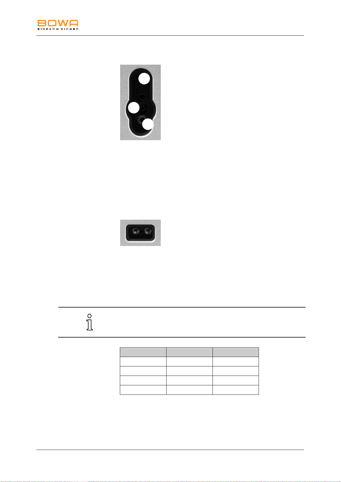
3.3. Monopolar/bipolar multifunction socket
a BOWA multifunction (monopolar and bipolar)
3-Pin US type (monopolar)
b Martin (bipolar)
c 4 mm (monopolar, foot switched)
The multifunction socket 1 allows the connection of a monopolar
instrument with hand or foot switching, or a bipolar instrument with foot
switching.
The BOWA multifunction cable REF 220-345 for ARC 100 combines a
monopolar handpiece and the connecting cable for bipolar forceps in
one connection.
3.4. Connection socket for neutral electrode
US-type neutral
Applied part of Type F according to IEC 60601-1
The neutral electrode connector socket is suitable for neutral electrode
plugs with two sockets.
3.5. Activation and alarm signals in monopolar and
bipolar mode
Pos: 19 /679-BOWA/HF-Geräte/ARC 200/250/300e/3 F unktionsweise/N ot-Aus @ 4\ mod_12701071 71492_258.doc @ 38126 @ 2
900-100_IFU-V1.0_11587-S0-20141209-EN ARC 100 Operating Manual 21
Page 22

3 Functionality
Always use the largest possible electrode when attaching a neutral
electrode.
BOWA recommends using split neutral electrodes, since only this type of
electrode allows the HF device to detect detachment of the neutral
electrode if this occurs.
3.6. Emergency stop
The HF device can be switched off at any time by using the on/off switch
25 as an emergency stop.
3.7. Monitoring functions
3.7.1. Self-test
When the HF device is switched on, it runs a self-test that checks the
operating elements, acoustic signal, microprocessor and hardware for
proper operation. If errors occur, see Section Detecting and correcting
faults, page 33.
3.7.2. Cyclical test during operation
During operation, safety-relevant functions and signals are tested
cyclically. If errors are detected, the HF generator will shut itself off. An
error code will be indicated using the power display. For further
information, see Section Detecting and correcting faults, page 33.
Pos: 21 /679-BOWA/HF-Geräte/ARC 300/350/3 Fun ktionsweise/ARC C ontrol-Technol ogie @ 4\mod _12610404799 28_258.doc @ 3 4728 @ 2
3.8. Neutral electrode monitoring
3.8.1. General information
Monitoring of the neutral electrode minimizes the risk of burns at the site
where the neutral electrode is attached.
Two types of neutral electrodes can be monitored:
Non-split neutral electrodes
Split neutral electrodes.
The split neutral electrodes are shown on indicator 15, and the onepiece neutral electrodes are shown on indicator 14; see Section Fault
indications for EASY monitoring, page 34.
22 ARC 100 Operating Manual 900-100_IFU-V1.0_11587-S0-20141209-EN
Page 23

3 Functionality
Article No.
Designation
901-012
Single pedal foot switch
3.8.2. EASY neutral electrode monitoring (EASY monitoring)
The EASY monitoring system measures changes in resistance between
the patient and the high-frequency surgery device both before and
during HF activation. If required, it requests personnel to intervene via
an optical and acoustic alarm. For this purpose, a split neutral electrode
with corresponding contact surfaces and suitable transition resistances
which is attached to the patient according to the manufacturer's
instructions is required. The EASY system does not monitor the currents
in the individual sections of split neutral electrodes.
3.9. Foot switches
In addition to the manual switch, the foot switch can be used to activate
various operating modes.
The foot switches are connected to socket connector 30.
The following foot switch can be connected to the HF device:
900-100_IFU-V1.0_11587-S0-20141209-EN ARC 100 Operating Manual 23
Page 24
4 Description
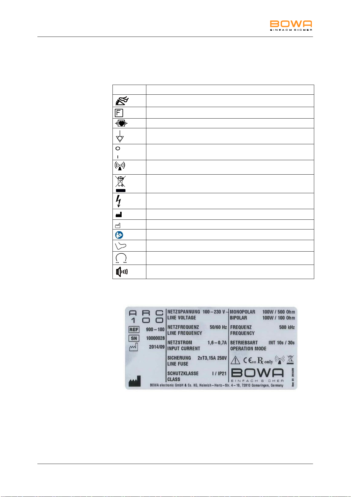
Symbol
Designation
Foot switch connection
Neutral electrode at HF insulated from ground
CF-type device with defibrillation protection
Potential equalization connection
On/off switch
HF energy in the range of 9 kHz to 400 GHz is used when the HF
device is activated. This energy generates electromagnetic radiation.
Labelling of electrical and electronic devices in accordance with
Directive 2002/96/EC (WEEE); see "Disposal"
Identification of (active) HF output; caution: dangerous electrical
voltage!
Manufacturer
Date of manufacture
Observe operating instructions
Foot switch
Volume adjustment range
Volume control
4. Description
4.1. Symbols on the device
4.1.1. Rating label
Figure 4-1: ARC 100 rating label
24 ARC 100 Operating Manual 900-100_IFU-V1.0_11587-S0-20141209-EN
Page 25

4 Description
4.2. Scope of delivery
ARC 100
Power cable
CD including training video
Operating instructions
You'll find detailed information on the scope of delivery in the current
catalogues.
4.3. Components required for operation
Power cable
Monopolar accessories:
Monopolar connecting cable
Monopolar instrument
Neutral electrode
Connecting cable for neutral electrode
Bipolar accessories:
Bipolar connecting cable
Bipolar instrument
- and / or Foot switch
Pos: 30 /679-BOWA/HF-Geräte/ARC 200/250/300e/1 1 Technische Date n/Betriebsbeding ungen @ 6\ mod_12985538 63128_258. doc @ 48688 @ 2
4.4. Operating conditions
Temperature: +10 °C to +40 °C
Relative humidity: 30% to 75%, non-condensing
Atmospheric pressure: 700 hPa to 1060 hPa
Maximum operating altitude: 3600 m AMSL
900-100_IFU-V1.0_11587-S0-20141209-EN ARC 100 Operating Manual 25
Page 26
5 Preparation
NOTE
Electromagnetic fields are generated during normal use of the HF
device. This can adversely affect other devices.
Ensure that no electronic devices are placed in the vicinity of the
HF device.
WARNING
Shock hazard
Always connect the HF device to a grounded power distribution
system in order to prevent electric shock.
DANGER
Risk of burns to patients due to excessive leakage current
Locate the HF device outside the immediate vicinity of the patient;
see Section Ambient conditions, page 13.
HF devices may be used only in rooms used for medical purposes that
meet the requirements of DIN VDE 0100-710.
If the HF device was previously stored or transported at temperatures
below +10 °C or at a relative humidity above 75%, non-condensing, it will
take approximately three hours to adjust to room temperature.
5. Preparation
5.1. Setting up the HF device
1. Observe the specified operating conditions; see Section Operating
conditions, page 25.
2. Place the HF device on one of the following platforms:
a table,
an equipment trolley;
a console suspended from a ceiling support or wall-
mounted brackets.
Do not place any device on the HF device.
3. Place the HF device a sufficient distance away from other
electronic equipment; see Section EMC, page 47.
4. Position the HF device with the front of the device facing the patient
and surgeon.
5. Do not place any other objects on or above the HF device.
6. Do not place the HF device on top of other devices.
26 ARC 100 Operating Manual 900-100_IFU-V1.0_11587-S0-20141209-EN
Page 27

5 Preparation
Do not use the HF device if the display components are not working. See
Section Detecting and correcting faults, page 33 for troubleshooting
instructions.
7. Connect the power cord.
5.2. Switching on the HF device
1. Switch the HF device on using the on/off switch 25.
The HF device carries out a self-test: all indicator lamps light up.
2. Check that all LEDs (3, 4, 5, 10, 11, 12, 13, 14, 15, 16,18, 19, 20,
23, 24) on the front panel light up.
The HF device is ready for operation.
The parameters for the most recently selected program appear on
the front panel.
Pos: 34 /679-BOWA/HF-Geräte/ARC 200/250/300e/5 Vor bereitung/Zu behör anschließ en @ 6\mod_1 29706613244 9_258.doc @ 47913 @ 233
5.3. Connecting instruments
Before connecting instruments, ensure that the following conditions
are met:
Combinations of accessories not mentioned in the
operating manual may be used only if they are explicitly
designed for the intended use. Performance features as
well as safety requirements must always be taken into
account.
The insulation of the accessories (e.g. HF cables,
instruments) must be sufficient for the maximum output
peak voltage (see IEC 60601-2-2 and IEC 60601-2-18).
Do not use accessories with defective insulation.
5.3.1. Instruments for monopolar applications
1. Plug the neutral electrode cable into the socket for the neutral
electrode 2.
2. Check monitoring for a non-split neutral electrode 14 or EASY
monitoring for a split neutral electrode 15 to ensure that it
corresponds to the type of neutral electrode connected.
3. Connect the electrode handpiece to the active connector socket 1.
– or –
For accessories without finger sensors: Connect the foot switch to
the connector socket 30. Connect the monopolar connection cable
with a 3-pin or 4 mm plug to connector socket 1.
5.3.2. Instruments for bipolar applications
1. Connect the bipolar cable with the instrument, e.g. the forceps.
2. Connect the bipolar cable to the active connector socket 1.
3. For bipolar use, connect the foot switch to the connector socket 30.
900-100_IFU-V1.0_11587-S0-20141209-EN ARC 100 Operating Manual 27
Page 28

5 Preparation
The neutral electrode used for this test may not later be used for an
operation.
5.3.3. Connecting the foot switch
Connect the desired foot switch to the foot switch connector socket
30.
5.3.4. Assigning a foot switch output
1. Press the button for "Foot switch" 17 repeatedly in order to assign
the foot switch to the desired current type.
When indicator 18 lights up, the foot switch is assigned to bipolar
coagulation; indicator lamp 19 is for monopolar cutting and
indicator 20 is for monopolar coagulation.
5.4. Functional test
5.4.1. Autotest function
The HF device automatically carries out a self-test after being switched
on and a cyclical test during operation. If errors occur, see
Section Detecting and correcting faults, page 33.
5.4.2. Functional test execution
Perform the following functional test before putting the device into
service:
1. Connect a split single-use neutral electrode and attach it to the
patient’s arm.
The EASY neutral electrode indicator 15 changes to green.
2. Remove the neutral electrode.
The indicator 16 changes to red, and the EASY neutral electrode
monitoring indicator 15 goes dark.
3. Press the surfaces of the neutral electrode against each other.
The EASY neutral electrode monitoring indicator 15 changes back
to green.
4. Connect a monopolar HF handpiece to the multifunction socket 1
and use the hand and foot switches to individually activate “Cut”
and “Coag”.
5. Check the settings on the display.
6. Connect a bipolar forceps to the multifunction socket 1 and activate
coagulation on a piece of wet gauze using the foot switch.
28 ARC 100 Operating Manual 900-100_IFU-V1.0_11587-S0-20141209-EN
Page 29
5 Preparation
NOTE
Risk of incorrect application of the neutral electrode
Ensure compliance with the specifications for correct application of
the neutral electrode with regard to size, adhesive properties and
full-surface contact of the complete electrode.
Actual status
Output
Measure
Cable for one-piece or split neutral
electrode not connected
Indicators for monitoring of non-split
neutral electrode 14 or EASY
monitoring of split neutral electrode
15 do not light up
Plug in the cable for the one-
piece or split neutral electrode.
Only the cable for the one-piece or
split neutral electrode is connected
Indicators for monitoring of non-split
neutral electrode 14 or EASY
monitoring of split neutral electrode
15 light up
Check the cable for a short
circuit.
Cable with split neutral electrode
plugged in but not attached to
patient.
Indicators for monitoring of non-split
neutral electrode 14 or EASY
monitoring of split neutral electrode
15 light up
Check whether the electrode is
correctly attached to the cable
connection.
The cable for the split or one-piece
neutral electrode is plugged in and
attached to the patient.
The indicators for monitoring of the
non-split neutral electrode 14 or
EASY monitoring of the split neutral
electrode 15 light up green, but the
type of neutral electrode is not
correctly detected.
Based on the assessment of
benefit and harm, decide
whether you should activate the
HF device.
5.4.3. Actions in case of problems
Proceed as follows in case of functional problems:
1. Immediately disconnect the patient from the HF device.
2. Inspect the HF device and perform a functional test.
3. Report incidents and near-accidents to the German Federal
Institute for Medications and Medical Products in accordance with
Section 3 of the German Ordinance on the Installation, Operation
and Use of Medical Products (MPBetreibV). Observe the provisions
of the in-house reporting system in this regard.
4. Contact our technical service; see Section Technical service,
page 38.
5.4.4. EASY neutral electrode monitoring
(EASY monitoring)
The following functions can be tested for split and one-piece neutral
electrodes:
900-100_IFU-V1.0_11587-S0-20141209-EN ARC 100 Operating Manual 29
Page 30
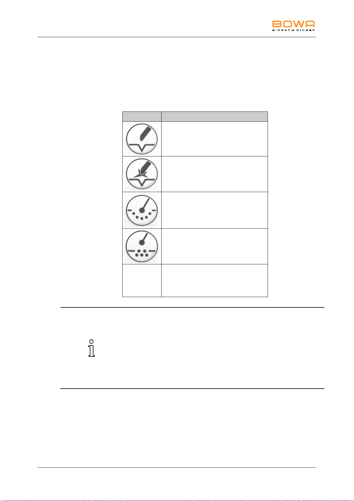
6 Operation
Mode icon
Designation
Monopolar cutting - Pure
Monopolar cutting - Dry
Monopolar coagulation - Moderate
Monopolar coagulation - Forced
-
Bipolar coagulation
The data about points of application and the use of instruments is based on
clinical practice. However, these are only basic guidelines which must be
tested and approved for suitability by the operator. Depending on the
individual conditions, it may be necessary to deviate from the specified data.
Medicine is continuously evolving and growing due to R&D and clinical
practice. These developments may also make deviations from the specified
data necessary.
Please contact the medical product consultants authorized by BOWA
regarding recommendations for settings.
6. Operation
6.1. Mode overview
An overview of the modes that can be employed with the HF device is
shown below.
30 ARC 100 Operating Manual 900-100_IFU-V1.0_11587-S0-20141209-EN
Page 31

6 Operation
6.2. Basic settings
6.2.1. Selecting the mode
Use the following procedure to call up the selectable current types:
1. For monopolar cutting or coagulation press the corresponding
button/display 6/7/8/9.
The corresponding LED 10/11/12/13 lights up.
2. Connect the instruments; see Section Connecting instruments,
page 27.
6.2.2. Setting power levels
Ten power levels are available for each mode.
1. Press the keys 21/22 to raise or to lower the power.
The number of lit LEDs 23 indicates the current power level.
6.2.3. Changing the volume
1. Turn the knob 28 on the rear of the device to adjust the volume.
6.3. Mode descriptions
The following recommendations are based on empirical values and
must be verified in each individual case by the surgeon.
Pos: 42 /679-BOWA/HF-Geräte/ARC 200/250/300e/6 Be dienung/Progra mm 0 "Standard" @ 5\mo d_12701083644 76_258.doc @ 38 299 @ 3
6.3.1. Monopolar cutting, "Pure"
In this mode a high-performance HF current with a low crest factor is
used for cutting biological tissue.
Application areas
Cutting tissue with low electrical resistance, such as muscle tissue or
vascular tissue.
Cutting or preparing fine structures.
Suitable instruments
Needle electrodes
Knife electrodes
Spatula electrodes
Sling electrodes
Pos: 43 /679-BOWA/HF-Geräte/ARC 200/250/300e/6 Be dienung/Progra mm 1 "Macr o" @ 6\mod_1 297072010043_2 58.doc @ 480 27 @ 3
6.3.2. Monopolar cutting, "Dry"
This mode is used for monopolar dry cutting. A large, controlled arc is
generated, which allows significantly deeper coagulation to be obtained.
Application areas
Operations in which pronounced haemostases are needed during the
cutting process.
900-100_IFU-V1.0_11587-S0-20141209-EN ARC 100 Operating Manual 31
Page 32

6 Operation
Cardiac surgery and blood coagulation in retracting blood vessels in the
sternum region.
Suitable instruments
Knife electrodes
Spatula electrodes
Ribbon snare electrodes
Pos: 44 /679-BOWA/HF-Geräte/ARC 200/250/300e/6 Be dienung/Progra mm 2 "Micro" @ 6\mod_12 97071058574 _258.doc @ 4798 9 @ 3
6.3.3. Monopolar coagulation, "Moderate"
This mode is used in contact coagulation for stopping haemorrhagic
oozing, haemostasis of larger tissue areas, and coagulation over
smaller surfaces. Carbonisation of the tissue is prevented and adhesion
of the electrode to the tissue is greatly reduced. A greater coagulation
depth is achieved in comparison to the other coagulation modes.
Application areas
Coagulation with high penetration, little adhesion of the electrode to the
tissue.
Suitable instruments
Electrodes with large contact area, e.g. ball-type electrodes
6.3.4. Monopolar coagulation, "Forced"
This mode is used for contact coagulation extending only over a small
area of the tissue, preferably with small surfaces and fine electrodes. A
high degree of coagulation with moderate cutting tendency is achieved.
Application areas
Rapid coagulation with low penetration and moderate cutting tendency.
Suitable instruments
Knife electrodes
Spatula electrodes
Isolated monopolar forceps
6.3.5. Bipolar coagulation
This mode is employed for arc-less contact coagulation when using
forceps. The use of a neutral electrode is not necessary.
Application areas
Bipolar coagulation
Suitable instruments
Bipolar forceps
Bipolar scissors
Pos: 47 /679-BOWA/HF-Geräte/ARC 200/250/300e/6 Be dienung/Progra mm 5 "Argon Fl ex" (nur mit O ption GastroCUT) @ 6\mo d_129707240169 9_258.doc @ 48065 @ 3
32 ARC 100 Operating Manual 900-100_IFU-V1.0_11587-S0-20141209-EN
Page 33

7 Detecting and correcting faults
LED code
Cause
Corrective measures
1
EASY neutral electrode fault
Check the neutral electrode and the neutral
electrode cable.
2
The YELLOW button on the
finger switch is in an actuated
state when switching on the
unit.
Switch on the device using the on/off switch
25 and do not actuate any other operating
elements at the same time.
If the problem persists, replace the
connected instrument and/or the foot switch.
3
The GREEN button on the
finger switch or the pedal on
the foot switch is in an
actuated state when switching
on the unit.
Switch on the device using the on/off switch
25 and do not actuate any other operating
elements at the same time.
If the problem persists, replace the
connected instrument and/or the foot switch.
4
Key on the front panel
pressed when switching on
the unit
Switch on the device using the on/off switch
25 and do not actuate any other operating
elements at the same time.
5-10
Internal fault
Restart the device.
If the error should recur, please contact our
technical service.
7. Detecting and correcting faults
Two types of faults can occur:
System errors
EASY monitoring faults
7.1. System errors
If a system error should occur, the fault status indicator 24 will light up
red. The combination with the lit display 23 indicates the corresponding
error.
7.1.1. Error list
Pos: 63 /679-BOWA/HF-Geräte/ARC 200/250/300e/7 F ehler/Fehler-List e @ 6\mod_ 1297147333340 _258.doc @ 48 257 @ 2
Errors not listed
Please contact the service centre in the event of errors that do not
appear in the error list; see Section Technical service, page 38.
If the expected change in the tissue does not occur and no error
message appears, check the parameters and the accessory
connections.
Visual and acoustic fault indications
The error messages are accompanied by visual and acoustic signals.
Furthermore, the generator cancels activation if certain errors occur and
the system is reset.
Please contact the service centre if the suggested corrective
measure does not eliminate the error; see Section Technical
service, page 38.
Errors are signalled with a lit Error LED 24 and Power LED 23:
900-100_IFU-V1.0_11587-S0-20141209-EN ARC 100 Operating Manual 33
Page 34

7 Detecting and correcting faults
Easy
monitoring 15
Cause
Indicator
Corrective measures
Switches from
green to
continuous red
When the monopolar
current is activated, a
significant problem
occurs
Marked increase in
the resistance
Depending on the
indication, there may
be heating under the
neutral electrode
An acoustic signal
sounds.
The Easy indicator 16
lights up red.
Check the neutral electrode
and the neutral electrode
cable; see Section Neutral
electrode monitoring,
page 22.
Check the neutral electrode
cable for proper connection
and external damage.
Loosened electrode
The Easy indicator 16
lights up red.
The device electronics
switch the output
socket 1 off.
Correct the position of the
neutral electrode. In the
case of continuing error
messages, replace the
neutral electrode.
7.2. Fault indications for EASY monitoring
When working with a split neutral electrode, the following faults may
occur:
34 ARC 100 Operating Manual 900-100_IFU-V1.0_11587-S0-20141209-EN
Page 35
8 Cleaning
NOTE
Incorrect use of the HF device can cause damage to the unit
Never sterilize the ARC 100 HF device. Instead, clean or disinfect
it.
WARNING
Risk of electric shock and fire!
Unplug the power cable before cleaning the device.
For surface cleaning, use approved cleaning agents and/or
disinfectants according to the manufacturer’s instructions.
Ensure that no liquid penetrates the device.
8. Cleaning
8.1. Preparation of the accessories
Prepare the accessories (e.g. surgical handpieces, instruments,
active electrodes, neutral electrodes and cables) as described in
the corresponding operating manuals.
Check the accessories before and after use for damage and
ensure that they are working properly.
8.2. Disinfection and cleaning
Pos: 66 /679-BOWA/HF-Geräte/ARC 200/250/300e/8 Aufbereitung/Desi nfizieren und R einigung @ 6\ mod_1297072 881168_258. doc @ 48122 @
1. Apply the cleaning agent and disinfectant.
2. Wipe the agent off with a sponge moistened with clean water or
with a cloth.
3. Dry the device using a clean, lint-free cloth.
Pos: 67 /679-BOWA/HF-Geräte/ARC 300/350/9 Wart ung/UE_Wartung/R eparatur @ 4\ mod_126104 0698397_258.doc @ 35203 @ 1
900-100_IFU-V1.0_11587-S0-20141209-EN ARC 100 Operating Manual 35
Page 36

9 Maintenance and repair
DANGER
Infection hazard
To avoid spreading germs and infections, disinfect the surface of
the device and pack it in addition to the shipping packaging before
it leaves the hospital or surgical practice.
9. Maintenance and repair
9.1. Maintenance
Check the device, the device trolley and the accessories (e.g. foot
switch, cable) after each use for damage or defects. In particular,
ensure that the insulation is intact on all cables.
Do not use any damaged device, damaged device trolley or
damaged accessories.
Replace defective accessories immediately.
Have the safety inspection for the device performed once a year.
Consult the appropriate service manual for additional technical
information.
9.1.1. Safety inspection
Safety inspections must be performed once a year.
The device and accessories may be inspected only by persons
who have the required training, knowledge or experience and who
can perform the inspection independently.
With regard to the safety inspection, you must comply with the
country-specific rules and regulations.
The inspector documents the inspection results and measured values
corresponding to the printed inspection protocol.
In the case of severe deviations from the values of the attached final
acceptance report, or if the specified maximum values were exceeded:
Send the HF device to the service centre; see Section Technical
service, page 38.
36 ARC 100 Operating Manual 900-100_IFU-V1.0_11587-S0-20141209-EN
Page 37

9 Maintenance and repair
NOTE
You can damage the HF device by doing your own repairs and
modifications of medical equipment
If a repair is necessary, have it done only by the service centre
specified below.
Never carry out any repairs yourself.
Fast and satisfactory repairs can only be guaranteed when all required
data have been supplied in full.
9.2. Repairs
BOWA is liable for safety, reliability and performance of the HF device
under the following conditions:
full compliance with all instructions regarding the installation
and proper use for the intended purpose contained in this
operating manual was maintained.
Changes, repairs, new settings and similar procedures have
been carried out only by persons authorised by BOWA to do
this work.
the electrical installations in the relevant room meet the local
requirements and statutory provisions.
The following information is required for returning the device:
complete address
model number
serial number
software version
Describe the problem, the appropriate application and the
accessories used.
– or –
Describe the repairs to be made.
900-100_IFU-V1.0_11587-S0-20141209-EN ARC 100 Operating Manual 37
Page 38

10 Storage
9.3. Technical service
Contact the following service centre for maintenance and repair work:
BOWA-electronic GmbH & Co. KG
Heinrich-Hertz-Strasse 4-10
72810 Gomaringen, Germany
Phone +49 (0) 7072-6002-0
Fax +49 (0) 7072-6002-33
E-mail: [email protected]
or visit our website:
www.bowa-medical.com
10. Storage
Pos: 71 /679-BOWA/HF-Geräte/ARC 300/350/10 Lag erung/Lagerung @ 4\mod_1261 040715569_25 8.doc @ 3527 9 @
If you store the HF device longer than one year, pay particular
attention to the indicators of the automatic function tests; see
Section Functional test, page 28.
Clean the HF device thoroughly before you put it into storage.
Store the HF device in a clean, dry place in accordance with the
storage conditions.
Storage conditions:
Temperature: -10 °C to +60 °C
Relative humidity 10 % to 85 %,
non-condensing
Atmospheric pressure: 500 hPa to 1060 hPa
38 ARC 100 Operating Manual 900-100_IFU-V1.0_11587-S0-20141209-EN
Page 39
11 Technical specifications
Insulation type / Classification
EMC
IEC 60601-1-2: 2007
Level of protection provided by the housing
IP 21
Protection class according to EN 60601-1
I
Type of application component as specified in EN
60601-1
CF
Compliance with standards
IEC 60601-1: 2005, +
Cor. 1:2006 + Cor. 2:2007 + A1:2013
IEC 60601-1-2: 2007,
IEC 60601-2-2: 2009,
IEC 60601-1-6:2010
IEC 60529:1989 + A1:1999
IEC 62304:2006
IEC 62366:2007
ISO 14971: 2007,
ISO 13485: 2003 + Cor.1: 2009
Classification according to EC Directive 93/42/EEC
IIb
Power connection
Power consumption in standby mode (100 V)
14 VA
Power consumption in standby mode (230 V)
30 VA
Line frequency
50/60 Hz
Maximum power consumption with 100 W HF output
power
160 VA
Connection for potential equalisation line
Yes
Voltage range 100 - 260 V
Input voltage range
100 V to 260 V
Current consumption in standby mode (100 V)
140 mA
Current consumption in standby mode (230 V)
130 mA
Current consumption at maximum HF output (100 V)
1.6 A
Current consumption at maximum HF output (230 V)
0.7 A
Mains fuses
2 x T3,15 A 250V
Dimensions and weight
External dimensions: width x height x depth (mm)
280 x 114 x 310
Weight
Approx. 5.6 kg
11. Technical specifications
11.1. Technical data for ARC 100
900-100_IFU-V1.0_11587-S0-20141209-EN ARC 100 Operating Manual 39
Page 40
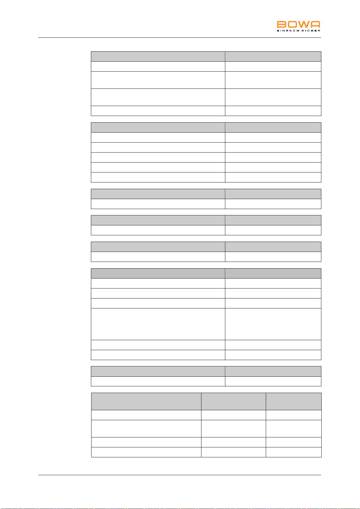
11 Technical specifications
Monitoring of the neutral electrode
EASY: Electrode Application System
Indicator for non-split or split electrode on the front
panel
Warning signal in the event of risk under the neutral
electrode
Visual, acoustic
Warning indicator on the front panel
Safety features
ISSys: Integrated Safety System
Self-test
Continuous status indication on the front panel
Display of operating errors on the front panel
Display of system errors on the front panel
Service support
Service support via ISSys
Cooling
Convection
Duty factor
Intermittent
10 sec / 30 sec (on/off)
Characteristics
Max. CUT power
100 W (at 500 Ω)
Max. COAG power
100 W (at 100 Ω)
Output frequency
500 kHz
Sockets
1x monopolar/bipolar multifunctional
socket, monopolar with foot switch
and finger switch, bipolar with foot
switch
Connection for foot switch
1x
Scope of delivery
Incl. User manual, mains cable
Compatibility
Permitted combination
Foot switch (REF 901-012)
Conditions of operation, transport and
storage
Operation
Transport and
storage
Temperature
+10°C to +40°C
-10°C to +60°C
Relative humidity
30 to 75%, noncondensing
10 to 85%, noncondensing
Atmospheric pressure
700 to 1060 hPa
500 to 1060 hPa
Operating altitude (max.)
3600 m above sea level
40 ARC 100 Operating Manual 900-100_IFU-V1.0_11587-S0-20141209-EN
Page 41
11 Technical specifications
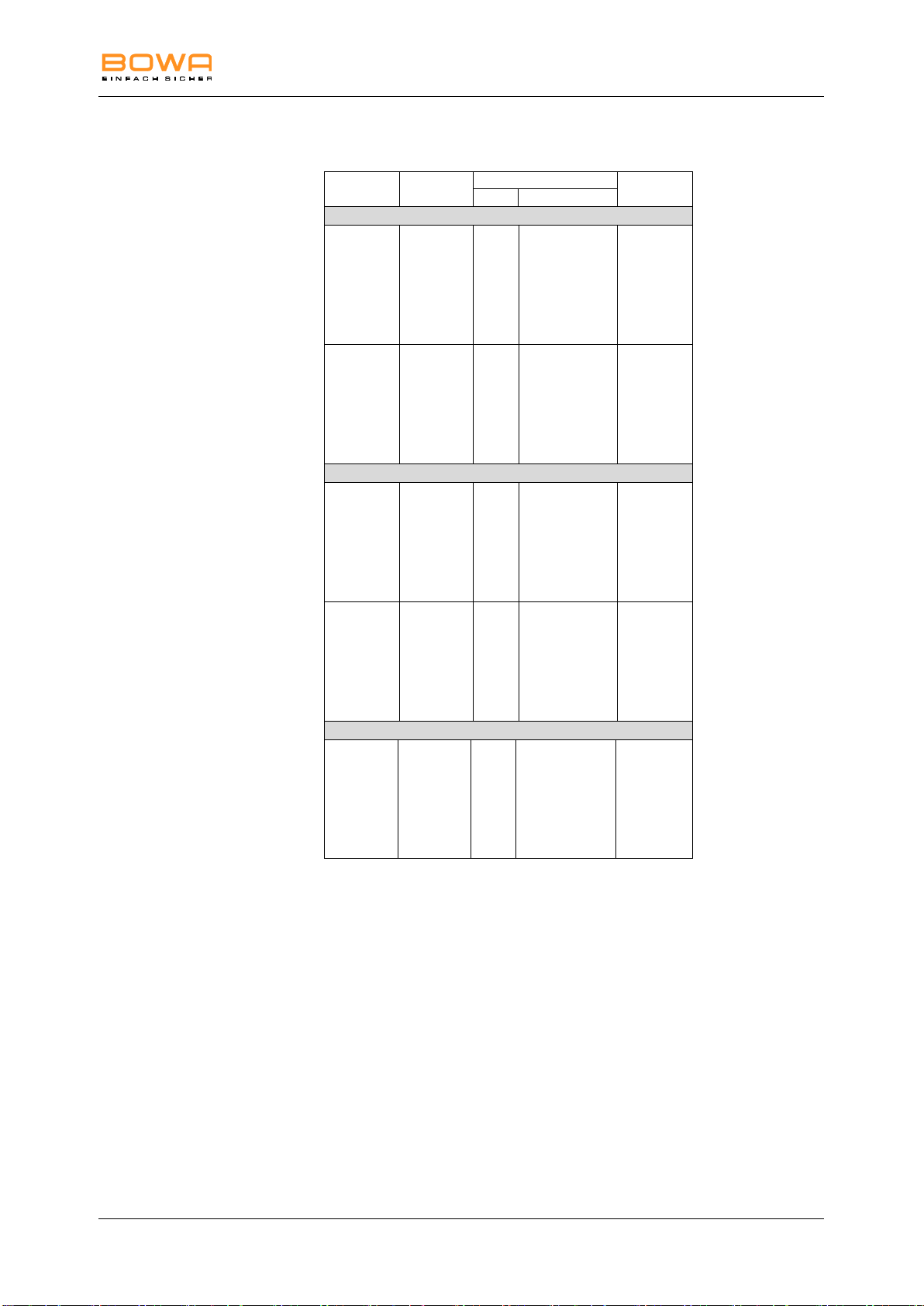
Description
Form of HF
voltage
Max. Power output
Peak voltage
Level
Power range
Monopolar Modes Cutting
Pure
Sinusoidal
constant
1
2
3
4
5
6
7
8
9
10
10 W - 100 W
300 Vp
480 Vp
600 Vp
730 Vp
810 Vp
950 Vp
1100 Vp
1200 Vp
1260 Vp
1380 Vp
Dry
Sinusoidal
modulated
1
2
3
4
5
6
7
8
9
10
10 W - 100 W
390 Vp
635 Vp
775 Vp
940 Vp
1100 Vp
1200 Vp
1250 Vp
1350 Vp
1440 Vp
1500 Vp
Monopolar Modes Coagulation
Moderate
Sinusoidal
constant
1
2
3
4
5
6
7
8
9
10
10 W - 100 W
150 Vp
190 Vp
250 Vp
295 Vp
317 Vp
360 Vp
370 Vp
100 Vp
420 Vp
440 Vp
Forced
Sinusoidal
modulated
1
2
3
4
5
6
7
8
9
10
10 W - 100 W
720 Vp
1040 Vp
1200 Vp
1380 Vp
1500 Vp
1680 Vp
1760 Vp
1890 Vp
2210 Vp
2340 Vp
Bipolar Mode Coagulation
Bipolar
Sinusoidal
constant
1
2
3
4
5
6
7
8
9
10
10 W - 100 W
117 Vp
158 Vp
195 Vp
227 Vp
246 Vp
270 Vp
290 Vp
315 Vp
335 Vp
346 Vp
Current types
900-100_IFU-V1.0_11587-S0-20141209-EN ARC 100 Operating Manual 41
Page 42
11 Technical specifications
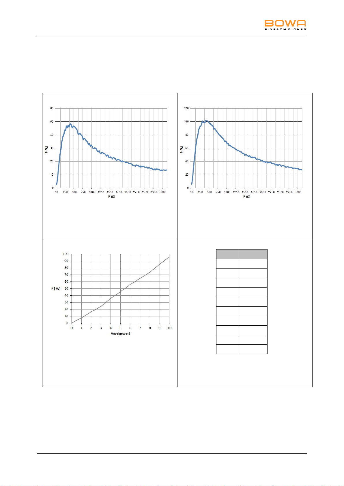
Values measured using non-inductive resistors
Graph of output power P [W] as a
function of the load resistance R [] for
the "Monopolar Cutting Pure" setting =
50 W
Values measured using non-inductive resistors
Graph of output power P [W] as a
function of the load resistance R [] for
the "Monopolar Cutting Pure" setting =
100 W
Graph of output power P [W] as a
function of the "Monopolar Cutting
Pure" setting. Design load resistance =
500
Level
U (Vp)
1
300
2
480
3
600
4
730
5
810
6
950
7
1100
8
1200
9
1260
10
1380
Table of HF output voltage U [Vp] as a
function of the "Monopolar Cutting
Pure" setting (no load)
11.2. Power, voltage and current charts
Monopolar cutting – Pure
42 ARC 100 Operating Manual 900-100_IFU-V1.0_11587-S0-20141209-EN
Page 43
11 Technical specifications
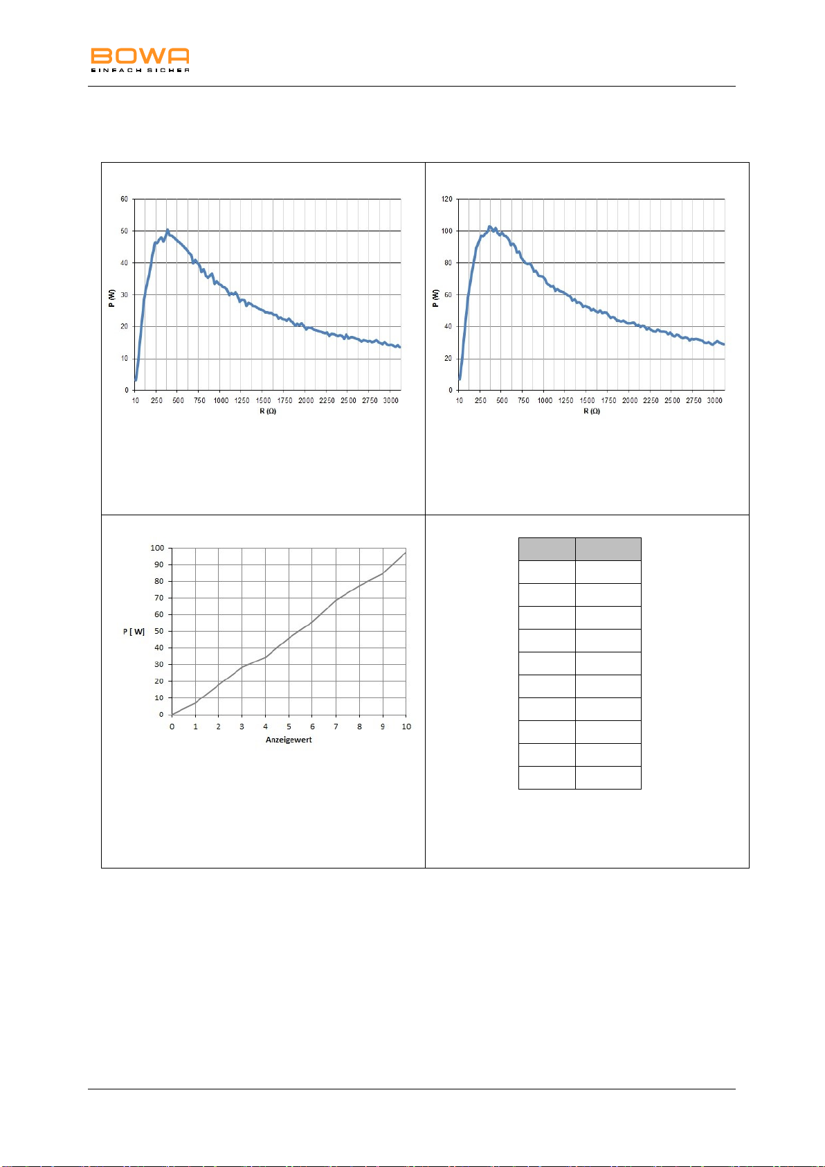
Values measured using non-inductive resistors
Graph of output power P [W] as a
function of the load resistance R [] for
the "Monopolar Cutting Dry" setting =
50 W
Values measured using non-inductive resistors
Graph of output power P [W] as a
function of the load resistance R [] for
the "Monopolar Cutting Dry" setting =
100 W
Graph of output power P [W] as a
function of the "Monopolar Cutting Dry"
setting. Design load resistance = 500
Level
U (Vp)
1
390
2
635
3
775
4
940
5
1100
6
1200
7
1250
8
1350
9
1440
10
1500
Table of HF output voltage U [Vp] as a
function of the "Monopolar Cutting Dry"
setting (no load)
Monopolar cutting – Dry
900-100_IFU-V1.0_11587-S0-20141209-EN ARC 100 Operating Manual 43
Page 44
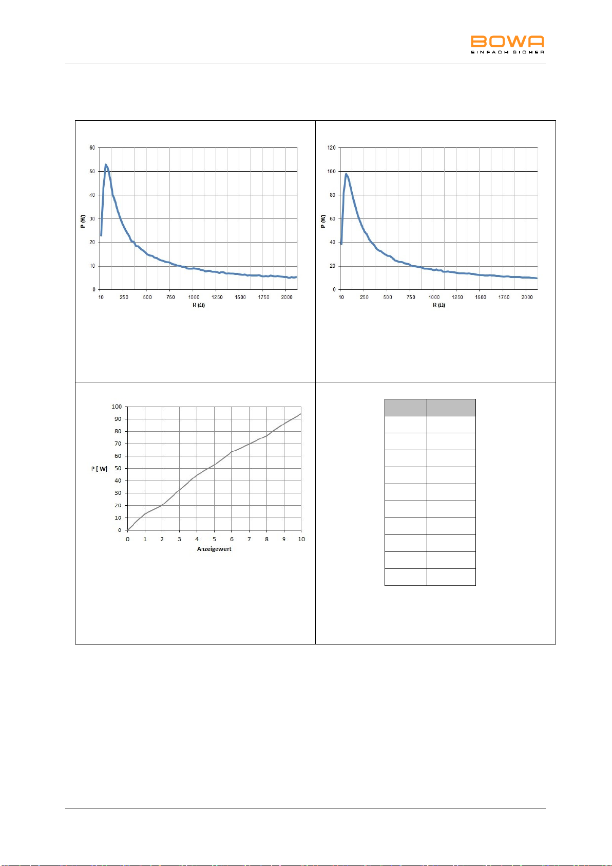
11 Technical specifications
Values measured using non-inductive resistors
Graph of output power P [W] as a
function of the load resistance R [] for
the "Monopolar Coagulation Moderate"
setting = 50 W
Values measured using non-inductive resistors
Graph of output power P [W] as a
function of the load resistance R [] for
the "Monopolar Coagulation Moderate"
setting = 100 W
Graph of output power P [W] as a
function of the "Monopolar Coagulation
Moderate" setting. Design load
resistance = 100
Level
U (Vp)
1
150
2
190
3
250
4
295
5
317
6
360
7
370
8
400
9
420
10
440
Table of HF output voltage U [Vp] as a
function of the "Monopolar Coagulation
Moderate" setting (no load)
Monopolar coagulation – Moderate
44 ARC 100 Operating Manual 900-100_IFU-V1.0_11587-S0-20141209-EN
Page 45
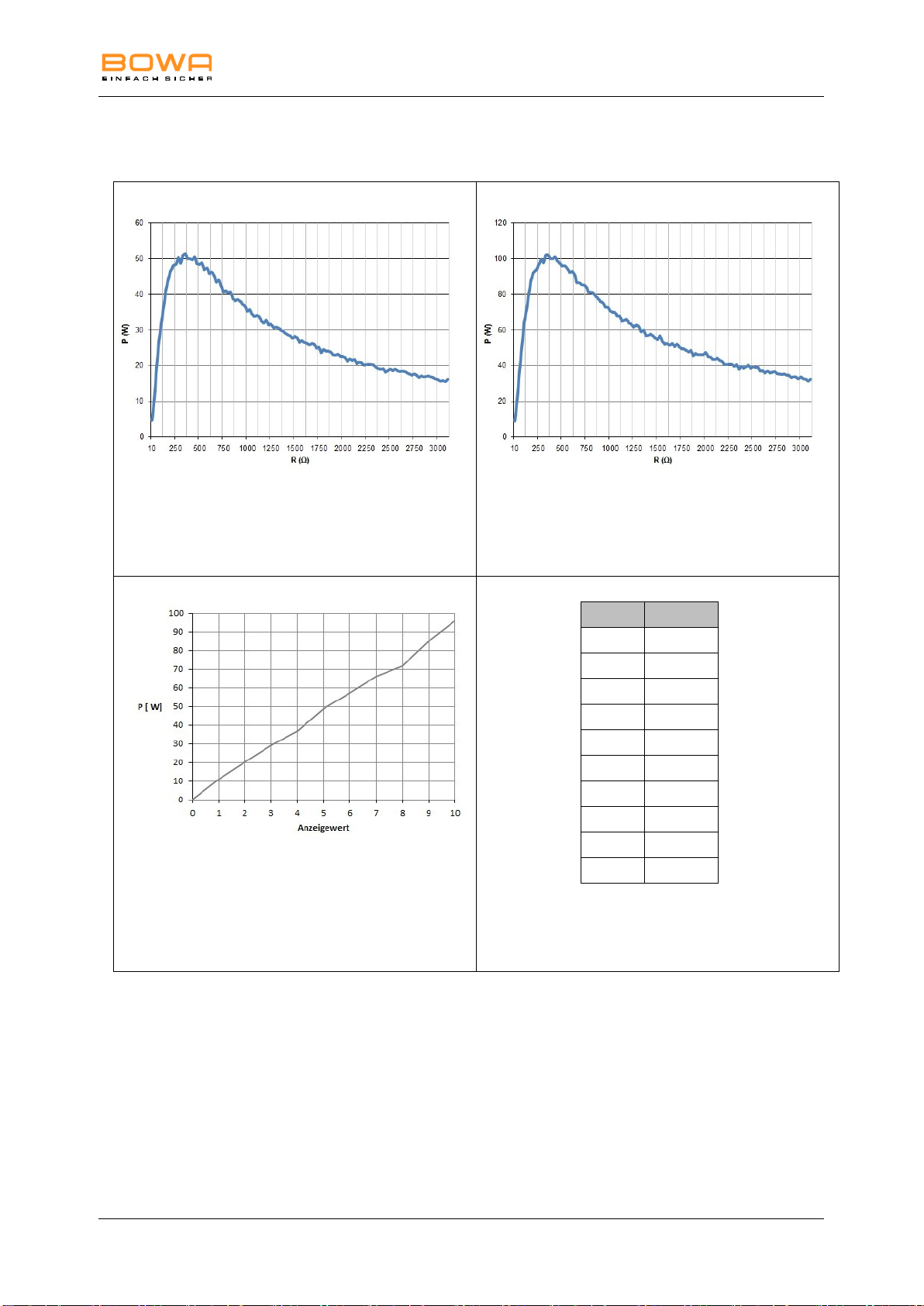
11 Technical specifications
Values measured using non-inductive resistors
Graph of output power P [W] as a
function of the load resistance R [] for
the "Monopolar Coagulation Forced"
setting = 50 W
Values measured using non-inductive resistors
Graph of output power P [W] as a
function of the load resistance R [] for
the "Monopolar Coagulation Forced"
setting = 100 W
Graph of output power P [W] as a
function of the "Monopolar Coagulation
Forced" setting. Design load resistance
= 500
Level
U (Vp)
1
720
2
1040
3
1200
4
1380
5
1500
6
1680
7
1760
8
1890
9
2210
10
2340
Table of HF output voltage U [Vp] as a
function of the "Monopolar Coagulation
Forced" setting (no load)
Monopolar coagulation – Forced
900-100_IFU-V1.0_11587-S0-20141209-EN ARC 100 Operating Manual 45
Page 46
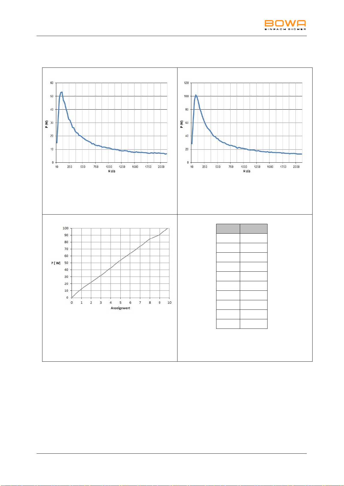
11 Technical specifications
Values measured using non-inductive resistors
Graph of output power P [W] as a
function of the load resistance R [] for
the "Bipolar Coagulation" setting =
50 W
Values measured using non-inductive resistors
Graph of output power P [W] as a
function of the load resistance R [] for
the "Bipolar Coagulation" setting = 100
W
Graph of output power P [W] as a
function of the "Bipolar Coagulation"
setting. Design load resistance = 100
Level
U (Vp)
1
117
2
158
3
195
4
227
5
246
6
270
7
290
8
315
9
335
10
346
Table of HF output voltage U [Vp] as a
function of the "Bipolar Coagulation"
setting (no load)
Bipolar coagulation
46 ARC 100 Operating Manual 900-100_IFU-V1.0_11587-S0-20141209-EN
Page 47

12 Accessories and replacement parts
Electromagnetic interference (IEC 60601-1-2, Table 201)
The ARC 100 is intended for operation in an electromagnetic environment as described below. The customer or
user of the ARC 100 should ensure that it is operated in such an environment.
Interference measurements
Conformity
Electromagnetic environment
guideline
HF emissions as specified in CISPR 11
Group 1
The ARC 100 must emit
electromagnetic energy in order to
perform its intended functions.
Nearby electronic devices may be
affected.
HF emissions as specified in CISPR 11
Class B
The ARC 100 is suitable for use in
facilities other than living areas and
those connected directly to the public
power supply network, which also
supplies buildings used for residential
purposes.
Emission of harmonics as specified in
IEC 61000-3-2
Class B
Emission of voltage fluctuations or flicker
as specified in IEC 61000-3-3
Conforms
12. Accessories and replacement parts
Pos: 76 /679-BOWA/HF-Geräte/ARC 300/350/12 Zube hör/Ersatzteile/Zu behör/Ersatzteil e @ 6\mod _129707781448 0_258.doc @ 4 8179 @
The BOWA multifunction cable REF 220-345 is optimally suited to the
operation of a monopolar handpiece and bipolar forceps on the ARC
100 because both connectors are combined in one plug.
Original BOWA accessories are suitable for use with devices in the ARC
and ARC PLUS families. When using accessories made by other
manufacturers, the user must ensure that they are designed for and
compatible with the maximum HF peak voltage of the HF device.
For the use and correct preparation of the autoclavable devices,
compliance with the relevant instruction manuals accompanying these
devices is required.
Detailed information on accessories and replacement parts is available
in the current accessories catalogue.
13. EMC
13.1. Guidelines and manufacturer's declaration in
accordance with DIN EN 60601-1-2, para.
6.8.3.201
900-100_IFU-V1.0_11587-S0-20141209-EN ARC 100 Operating Manual 47
Page 48

13 EMC
Electromagnetic immunity (IEC 60601-1-2, Table 202)
The ARC 100 is intended for operation in the electromagnetic environment described below. The customer or user
of the ARC 100 should ensure that it is operated in such an environment.
Tests for resistance to
interference
IEC 60601 test level
Conformity level
Electromagnetic
environment guidelines
Electrostatic discharge
(ESD) according to
IEC 61000-4-2
± 6 KV contact discharge
± 6 KV contact discharge
Floors should be made of
wood or cement or covered
with ceramic tiles. If the
floor is covered with
synthetic material, the
relative humidity must be at
least 30%.
± 8 KV air discharge
± 8 KV air discharge
Fast transient electrical
interference (bursts as per
IEC 61000-4-4
± 2 kV for power supply
lines
± 2 kV for power supply
lines
The quality of the mains
power should correspond to
that of a typical business or
hospital environment.
± 1 kV for input and output
lines
± 1 kV for input and output
lines
Surges as per
IEC 61000-4-5
± 1 kV voltage outer
conductor-outer conductor
± 1 kV voltage outer
conductor-outer conductor
The quality of the mains
power should correspond to
that of a typical business or
hospital environment.
± 2 kV voltage outer
conductor to ground
± 2 kV voltage outer
conductor to ground
Voltage collapses, brief
interruptions and
fluctuations in the power
supply as per IEC 610004-11
< 5% UT for ½ period
(> 95% dropout)
40 % UT for 5 periods
(60 % dropout)
70% UT for 25 periods
(30% dropout)
< 5% UT for 5 s
(> 95% dropout)
< 5% UT for ½ period
(> 95% dropout)
40 % UT for 5 periods
(60 % dropout)
70% UT for 25 periods
(30% dropout)
< 5% UT for 5 s
(> 95% dropout)
The quality of the mains
power should correspond to
that of a typical business or
hospital environment. If the
user of the ARC 100
requires it to continue
operating even in the
presence of power
interruptions, it is
recommended that the ARC
100 be supplied from an
uninterruptible power
supply or a battery.
Note: UT is the AC supply voltage prior to the application of the test level.
48 ARC 100 Operating Manual 900-100_IFU-V1.0_11587-S0-20141209-EN
Page 49
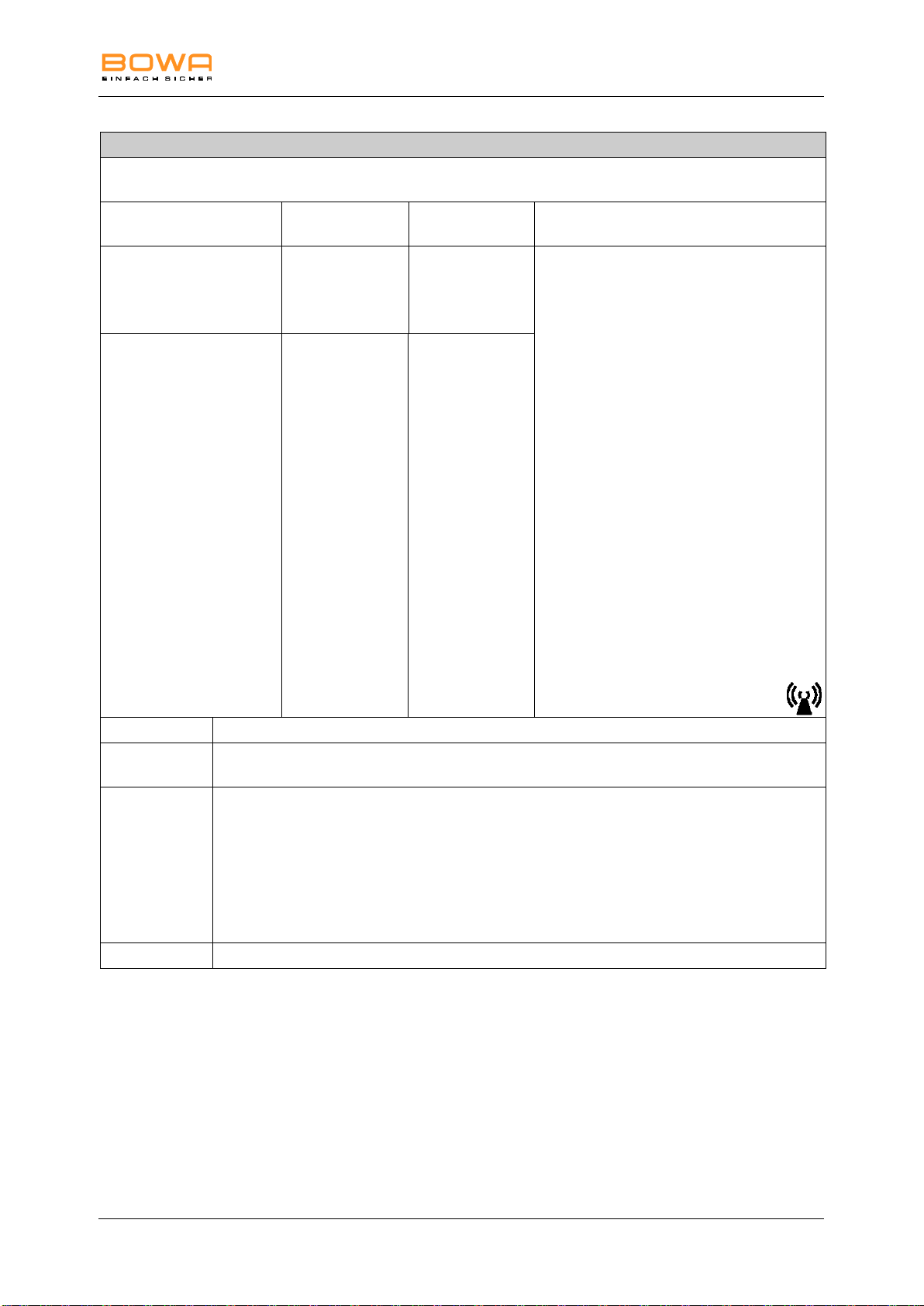
13 EMC
Electromagnetic immunity (IEC 60601-1-2, Table 204)
The ARC 100 is intended for operation in the electromagnetic environment described below. The customer or user
of the ARC 100 should ensure that it is operated in such an environment.
Tests for resistance to
interference
IEC 60601 test
level
Conformity level
Electromagnetic environment guidelines
Conducted HF interference
as per IEC 61000-4-6
3 V rms
150 kHz to
80 MHz
3 V
Portable and mobile wireless devices should
not be used within the recommended
protective working clearance from the ARC
100 and its cables, which is calculated using
the equation corresponding to the relevant
transmission frequency.
Recommended protective distance:
d = 0.35 × √P
d = 0.35 × √P for 80 MHz to 800 GHz
d = 0.7 × √P for 800 MHz to 2.5 GHz
where P is the nominal transmitter output in
watts (W) specified by the transmitter
manufacturer and d is the recommended
protective distance in meters (m).
The field strength of stationary transmitters
as determined by on-site measurementsa
should be lower than the compliance levelb at
all frequencies.
Interference is possible in the vicinity of
devices that bear the following symbol.
Radiated HF interference
as per IEC 61000-4-3
3 V/m
80 MHz to
2.5 GHz
3 V/m
Note 1
The higher frequency range applies in case of 80 MHz and 800 MHz.
Note 2
These guidelines may not be applicable in all cases. The propagation of electromagnetic waves
is influenced by their absorption and reflection by buildings, objects and people.
a
Field strengths from stationary transmitters such as base stations for wireless telephones and
land mobile radios, amateur radio, AM and FM radio broadcasting and TV broadcasting cannot
be predicted theoretically with accuracy. A study of the electromagnetic phenomena at the
location should be done to determine the electromagnetic environment resulting from stationary
transmitters. If the measured field strength at the location where the ARC 100 is being used
exceeds the aforementioned compliance level, the ARC 100 should be monitored to verify that it
is functioning properly. If unusual performance characteristics are observed, additional measures
may be necessary, such as repositioning or relocation of the ARC 100.
b
The field strength should be lower than 10 V/m over the frequency range of 150 kHz to 80 MHz.
900-100_IFU-V1.0_11587-S0-20141209-EN ARC 100 Operating Manual 49
Page 50
13 EMC
Recommended protective working clearances between portable and mobile HF
telecommunications devices and the ARC 100 (IEC 60601-1-2, Table 206)
The ARC 100 is designed for operation in an electromagnetic environment in which HF interference is monitored.
The customer or user of the ARC 100 can help to prevent electromagnetic interference by complying with the
minimum clearance between portable and mobile HF telecommunication devices (transmitters) and the ARC 100.
These clearances may vary depending on the output power of the relevant communication device as specified
below.
Nominal transmitter
output (W)
Protective distance (m) depending on transmission frequency
150 kHz to 80 MHz
d = 0.35 × √P
80 MHz to 800 MHz
d = 0.35 × √P
800 MHz to 2.5 GHz
d = 0.7 × √P
0.01
0.035
0.035
0.07
0.1
0.11
0.11
0.22
1
0.35
0.35
0.70
10
1.1
1.1
2.2
100
3.5
3.5
7.0
For transmitters whose maximum nominal output is not specified in the table above, the recommended protective
distance d in meters (m) can be determined using the equation in the corresponding column, where P is the
maximum nominal output power of the transmitter in watts (W) as specified by the transmitter manufacturer.
Note 1
The higher frequency range applies in case of 80 MHz and 800 MHz.
Note 2
These guidelines may not be applicable in all cases. The propagation of
electromagnetic waves is influenced by their absorption and reflection by buildings,
objects and people.
50 ARC 100 Operating Manual 900-100_IFU-V1.0_11587-S0-20141209-EN
Page 51
14 Disposal
Always comply with the national regulations of the relevant country when
disposing of or recycling the device or its components.
Symbol
Designation
A device marked with this symbol must be put into the separate
waste collection for electrical and electronic devices. Disposal
is carried out free of charge by the manufacturer within the
European Union.
14. Disposal
Pos: 80 /679-BOWA/HF-Geräte/ARC 300/350/14 Entsorgu ng/Entsorgu ng @ 4\mod_1 26104082952 2_258.doc @ 35 450 @
If you have any questions regarding the disposal of the device,
please contact our technical service; see Section Technical
service, page 38.
900-100_IFU-V1.0_11587-S0-20141209-EN ARC 100 Operating Manual 51
Page 52

0123
900-100_IFU-V1.0_11587-S0-20141209-EN
Printed in Germany Subject to technical and design changes Copyright by BOWA-electronic, Gomaringen │ Germany
BOWA-electronic GmbH & Co. KG
Heinrich-Hertz Strasse 4-10
D-72810 Gomaringen │ Germany
Phone: +49 (0) 7072-6002-0
Fax: +49 (0) 7072-6002-33
info@bowa-medical.com │ www.bowa-medical.com
CE-Kennzeichnung gemäß
Richtlinie 93/42/EWG
 Loading...