

Page 1

Gebrauchsanweisung
Prüfgerät für
Elektrodenhandgriffe und Kabel
050-230
MN030-423-IFU-M098-050230-S2-20100401 03/10
Page 2

Inhalt
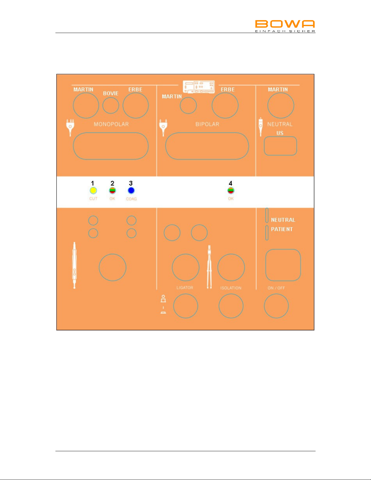
1. Anschluss-Positionen 3
2. Bestimmungsgemäße Verwendung 4
3. Bedienung 4
3.1 Einschalten und Funktionstest 4
3.2 Prüfen von Neutralelektroden-Anschlussleitungen 5
3.3 Prüfen von Bipolaren-Anschlussleitungen 5
3.4 Prüfen von Ligator-Anschlussleitungen 5
3.5 Prüfen von einpoligen Anschlussleitungen 6
3.6 Prüfen von Handgriffen mit Fingerschaltern 6
3.7 Prüfen von Pedal-Fußschaltern 6
4. Desinfizieren und Reinigen 7
5. Wartung/Reparatur 7
5.1 Technischer Service 7
6. Entsorgung 8
7. Technische Daten und Ausführung 8
8. Notizen 9
Seite 2 Prüfgerät MN030-423-IFU-M098-050230-S2-20100401
Page 3
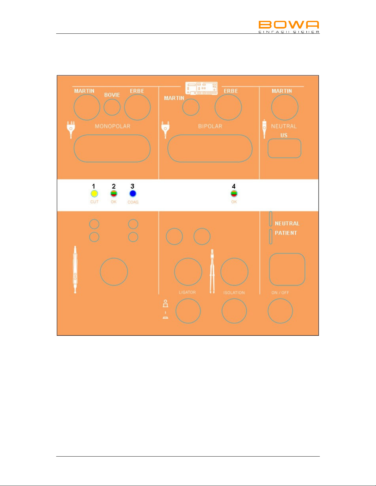
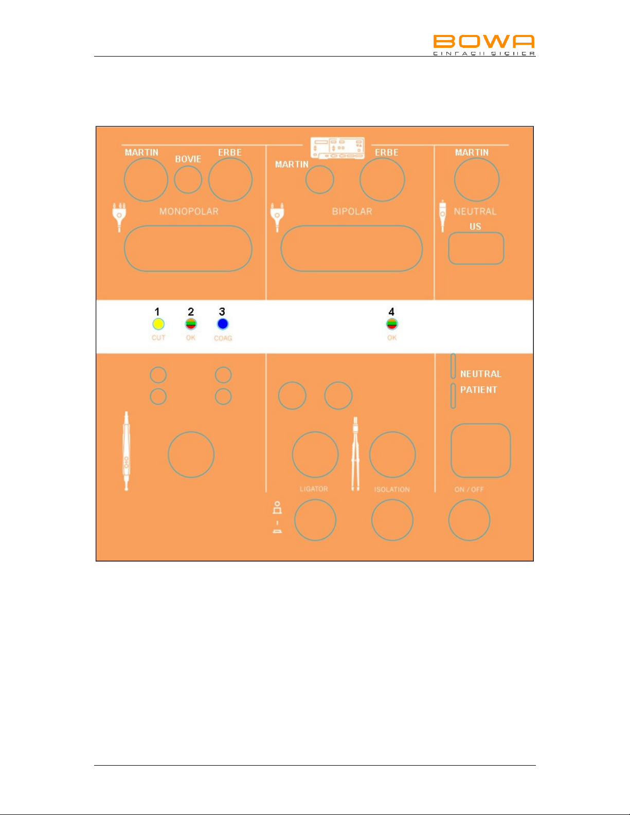
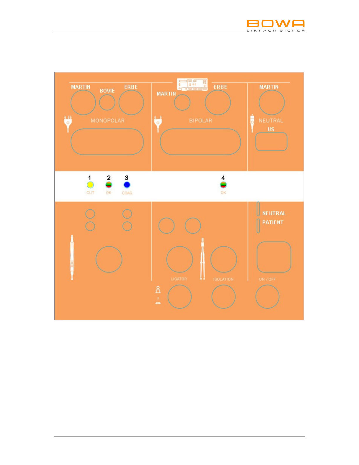
1. Anschluss-Positionen
050-230-IFU-V1.0-MN030-423-S2-20100401 Prüfgerät Seite 3
Page 4

2. Bestimmungsgemäße Verwendung
Das Prüfgerät dient zur Überprüfung von monopolaren Handgriffen sowie mono- und
bipolaren Handgriffen und Kabeln mit Valleylab-, ERBE- oder Martin-kompatiblem
Anschluss.
3. Bedienung
3.1 Einschalten und Funktionstest
• Steckernetzteil an Kleinspannungsbuchse mit Bajonettverschluss mit kurzer
Drehung anschließen.
• Steckernetzteil in Steckdose bauseitig stecken 100-240V AC möglich.
• Ein- / Ausschalter betätigen
Es folgt ein sichtbarer Einschalttest:
Alle LEDs leuchten
Ligator- & Isolation-Schalter blinken wechselseitig
danach leuchten die Statusanzeigen-LEDs von links nach rechts
1 2 3 4
Gelb – grün – blau – rot
Gelb – rot – blau – grün
Dummywiderstand wird in den Schaltkreis geschaltet um Sensor und OPV zu
testen.
- orange - orange
• Wenn Statusanzeige 2 und 4 orange leuchten wurde der Einschalt- und
Simulationstest erfolgreich abgeschossen.
Kabelprüfer ist nun betriebsbereit.
- oder -
Wenn Statusanzeige 4 orange / rot blinkt liegt ein Fehler vor.
Bitte wenden Sie sich an den technischen Service (siehe Kapitel
„5.1 Technischer Service“).
Achtung:
Aus messtechnischen Gründen darf immer nur ein Prüfling gesteckt sein!
Seite 4 Prüfgerät MN030-423-IFU-M098-050230-S2-20100401
Page 5
3.2 Prüfen von Neutralelektroden-Anschlussleitungen
Prüfen der unterschiedlichen Neutralelektrodenleitungen (rechte Seite des Gerätes).
Wählen Sie zu Ihrem Kabel die passende Steckung und adaptieren Sie zuerst die
Geräteseite danach die Instrumentenseite.
Statusanzeige „4“ wird bei gutem Prüfling grün leuchten. Jetzt sollte der Prüfling hin
und her bewegt werden um zu erkennen, ob ein Wackelkontakt vorhanden ist.
Gleichzeitig beginnt der Isolationsschalter zu blinken. Das bedeutet der
entsprechende Schalter muss betätigt werden um die Isolationsprüfung
durchzuführen.
Ist die Leitung in Ordnung, wird die Statusanzeige „4“ grün leuchten, auch hier muss
der Prüfling hin und her bewegt werden. Danach Prüfling entfernen.
Ist der Prüfling nicht in Ordnung leuchtet die Statusanzeige „4“ rot. In diesem Fall
den Prüfling entfernen und entsprechend markieren.
3.3 Prüfen von Bipolaren-Anschlussleitungen
Wählen Sie zu Ihrem Kabel die passende Steckung. Danach verfahren Sie wie bei
den Neutralelektrodenleitungen.
3.4 Prüfen von Ligator-Anschlussleitungen
Schalten Sie den Schalter, welcher mit Ligator bezeichnet, ist „EIN“.
Wählen Sie zu Ihrem Kabel die passende Steckung und adaptieren Sie zuerst die
Geräteseite danach die Instrumentenseite.
Statusanzeige „4“ wird bei gutem Prüfling grün leuchten. Jetzt sollte der Prüfling hin
und her bewegt werden, um zu erkennen ob ein Wackelkontakt vorhanden ist.
Gleichzeitig beginnt der Isolationsschalter zu blinken. Das bedeutet der
entsprechende Schalter muss betätigt werden um die Isolationsprüfung durch zu
führen.
Ist die Leitung in Ordnung wird die Statusanzeige „4“ grün leuchten, auch hier muss
der Prüfling hin und her bewegt werden. Danach Prüfling entfernen.
Ist der Prüfling nicht in Ordnung leuchtet die Statusanzeige „4“ rot oder bleibt
orange. In diesem Fall den Prüfling entfernen und entsprechend markieren.
050-230-IFU-V1.0-MN030-423-S2-20100401 Prüfgerät Seite 5
Page 6
3.5 Prüfen von einpoligen Anschlussleitungen
Wählen Sie zu Ihrem Kabel die passende Steckung auf der linken Seite des
Prüfgerätes und adaptieren Sie zuerst die Geräteseite danach die Instrumentenseite.
Statusanzeige „2“ wird bei gutem Prüfling grün leuchten jetzt sollte der Prüfling hin
und her bewegt werden, um einen evtl. vorhandenen Wackelkontakt festzustellen.
Ist die Leitung nicht in Ordnung wird die Statusanzeige „2“ rot blinken. In diesem
Fall den Prüfling entfernen und entsprechend markieren.
3.6 Prüfen von Handgriffen mit Fingerschaltern
Wählen Sie zu Ihrem Kabel die passende Steckung auf der linken Seite des
Prüfgerätes und adaptieren Sie zuerst die Geräteseite. Danach stecken Sie den
Handgriff in den vorgesehenen waagrechten Kontaktstift. Daraufhin muss die
Statusanzeige „2“ grün leuchten. Bewegen Sie das Kabel hin und her, die
Statusanzeige „2“ muss dauernd grün leuchten.
Ist das Kabel nicht in Ordnung wird die Statusanzeige „2“ rot blinken. In diesem Fall
den Prüfling entfernen und entsprechend markieren.
Betätigen Sie die Taste gelb für Cut. Es muss die Statusanzeige „1“ gelb leuchten.
Ist die Taste nicht in Ordnung wird die Statusanzeige „2“ rot blinken oder zeigt keine
Reaktion. In diesem Fall den Prüfling entfernen und entsprechend markieren.
Betätigen Sie die Taste blau für COAG. Es muss die Statusanzeige „3“ blau
leuchten.
Ist die Taste nicht in Ordnung wird die Statusanzeige „2“ rot blinken oder zeigt keine
Reaktion. In diesem Fall den Prüfling entfernen und entsprechend markieren.
3.7 Prüfen von Pedal-Fußschaltern
Wählen Sie die Buchse an der Frontseite des Prüfgerätes. Adaptieren Sie den Fußschalter.
Bedienen Sie nacheinander die Pedale. Die Statusanzeige wird entsprechend der
Pedalfarbe leuchten. Statusanzeige „2“ ist für das dritte Pedal und wird von orange
auf grün wechseln.
Ist der Pedalfußschalter nicht in Ordnung werden die Anzeigen nicht reagieren und
nicht leuchten, die Statusanzeige „2“ bleibt orange. In diesem Fall den Prüfling
entfernen und entsprechend markieren.
Seite 6 Prüfgerät MN030-423-IFU-M098-050230-S2-20100401
Page 7
4. Desinfizieren und Reinigen
Hinweis
Beschädigung des Prüfgerätes durch falsche Handhabung!
Sterilisieren Sie das Prüfgerät niemals. Reinigen oder desinfizieren Sie es.
Warnung
Stromschlag- und Brandgefahr!
Ziehen Sie vor der Reinigung den Netzstecker.
Verwenden Sie für die Flächenreinigung zugelassene Reinigungs-
/Desinfektionsmittel nur nach Anweisung des Herstellers.
Stellen Sie sicher, dass keine Flüssigkeit in das Gerät eindringt.
Reinigung
Das Gehäuse mit einem feuchten Lappen und mildem Reinigungsmittel abwischen.
Zur Reinigung keine Scheuer- oder Lösungsmittel verwenden. Schmutz
und/oder Feuchtigkeit in den Anschlüssen kann die Prüfungen beeinträchtigen.
5. Wartung/Reparatur
Hinweis
Beschädigung des Prüfgerätes durch eigenhändig ausgeführte Reparaturmaßnahmen und Modifikationen!
Wenden Sie sich im Reparaturfall ausschließlich an die unten genannte Service-
Adresse.
Führen Sie keinesfalls eigenhändig Reparaturen durch.
BOWA übernimmt die Haftung für Sicherheit, Zuverlässigkeit und Leistung des
Prüfgerätes unter folgenden Bedingungen:
• Alle Anweisungen zur Installation und zum bestimmungsgemäßen
Gebrauch gemäß dieser Gebrauchsanweisung wurden genau befolgt.
• Änderungen, Reparaturen, Neueinstellungen u. Ä. wurden nur von
Personen ausgeführt, die für diese Arbeiten von BOWA autorisiert wurden.
• Die elektrischen Installationen in dem betreffenden Raum entsprechen den
örtlichen Vorschriften und gesetzlichen Bestimmungen.
5.1 Technischer Service
Für Wartung und Reparatur wenden Sie sich an folgende Service-Adresse:
BOWA-electronic GmbH & Co. KG
Heinrich-Hertz-Strasse 4–10
72810 Gomaringen/Germany
Telefon +49 (0) 7072-6002-0
Telefax +49 (0) 7072-6002-33
oder im Internet unter:
www.bowa-medical.com
050-230-IFU-V1.0-MN030-423-S2-20100401 Prüfgerät Seite 7
Page 8

6. Entsorgung
Das Gerät kann am Ende seiner Nutungsdauer wie gewöhnlicher Elektronikschrott
entsorgt werden. Die Entsorgung des Prüfgerätes, des Verpackungsmaterials sowie
des Zubehörs muss unbedingt nach den jeweils geltenden länderspezifischen
Vorschriften und Gesetzen erfolgen.
7. Technische Daten und Ausführung
Steckernetzteil: 100 VAC – 240 AC, 50 / 60Hz
Eingangsstrom 400mA
Spannungsgeregelt, strombegrenzt
Ableitstrom < 10uA
Nennspannung: 15 Volt DC
Nennstrom: 0,5 A DC
Frequenz MCU: 16 MHz
Frequenz Handgriff: 20 kHz
Frequenz Kabelmessung: 5 bis 20 Hz
Schnittstelle intern: RS232
Prüfkriterien: Widerstand Anschlussleitungen < 10 Ohm
Status-Anzeigen: orange (beide Statusanzeigen) = Betriebsbereit
Gehäuse: Kunststoff mit Aufstellfüßen zum Pult.
Lagerbedingungen:
Umgebungs-
bedingungen:
Isolation / Klassifizierung:
Normenkonformität DIN EN 61010:2002 + A1:2002 + A2:2004
EMV DIN EN 61326-1:2006
Schutzklasse II
Austauschbare Primäradapter
Handgrifftasten < 220 Ohm
Handgriffaktivleitung < 20 Ohm
Isolationswiderstand Leiter z. Leiter > 1 MOhm
Von Instrumentenseite aus gemessen,
Ligator- Anschlusskabel entsprechend Spezifikation
grün (dauernd) = Prüfling IN ORDNUNG
gelb = CUT – Taste betätigt
blau = COAG – Taste betätigt
rot / keine Reaktion = FEHLER
Abmessungen: B 240 x T 198 x H 110 mm
Gewicht: 1,5 kg
Temperatur Rel. Feuchtigkeit Luftdruck
-20 °C bis +70 °C 10 - 100% 500 - 1060 hPa
-10 °C bis +60 °C 10 - 100% 800 - 1060 hPa
Seite 8 Prüfgerät MN030-423-IFU-M098-050230-S2-20100401
Page 9

8. Notizen
050-230-IFU-V1.0-MN030-423-S2-20100401 Prüfgerät Seite 9
Page 10
CE-Kennzeichnung gemäß
Richtlinie 2006/95/EG
BOWA-electronic GmbH & Co. KG
Heinrich-Hertz-Straße 4-10
D-72810 Gomaringen │ Germany
Telefon +49 (0) 7072 / 6002 - 0
Telefax +49 (0) 7072 / 6002 - 33
[email protected] │ bowa-medical.com
Technische Änderungen vorbehalten! MADE IN GERMANY
050-230-IFU-V1.0-MN030-423-S2-20100401
Page 11

Operating Manual
Testing Device for
Electrode Handles and Cables
050-230
MN030-423-IFU-M098-050230-S2-20100401 03/10
Page 12

Contents
1. Connection Positions 3
2. Intended Use 4
3. Operation 4
3.1 Switching on and functional test 4
3.2 Testing neutral electrode connecting cables 5
3.3 Testing bipolar connecting cables 5
3.4 Testing Ligator connecting cables 5
3.5 Testing unipolar connecting cables 6
3.6 Testing handles with finger switches 6
3.7 Testing pedal foot switches 6
4. Disinfecting and Cleaning 7
5. Maintenance/Repairs 7
5.1 Technical Service Center 7
6. Disposal 8
7. Technical Data and Version 8
8. Notes 9
Page 2 Testing Device MN030-423-IFU-M098-050230-S2-20100401
Page 13
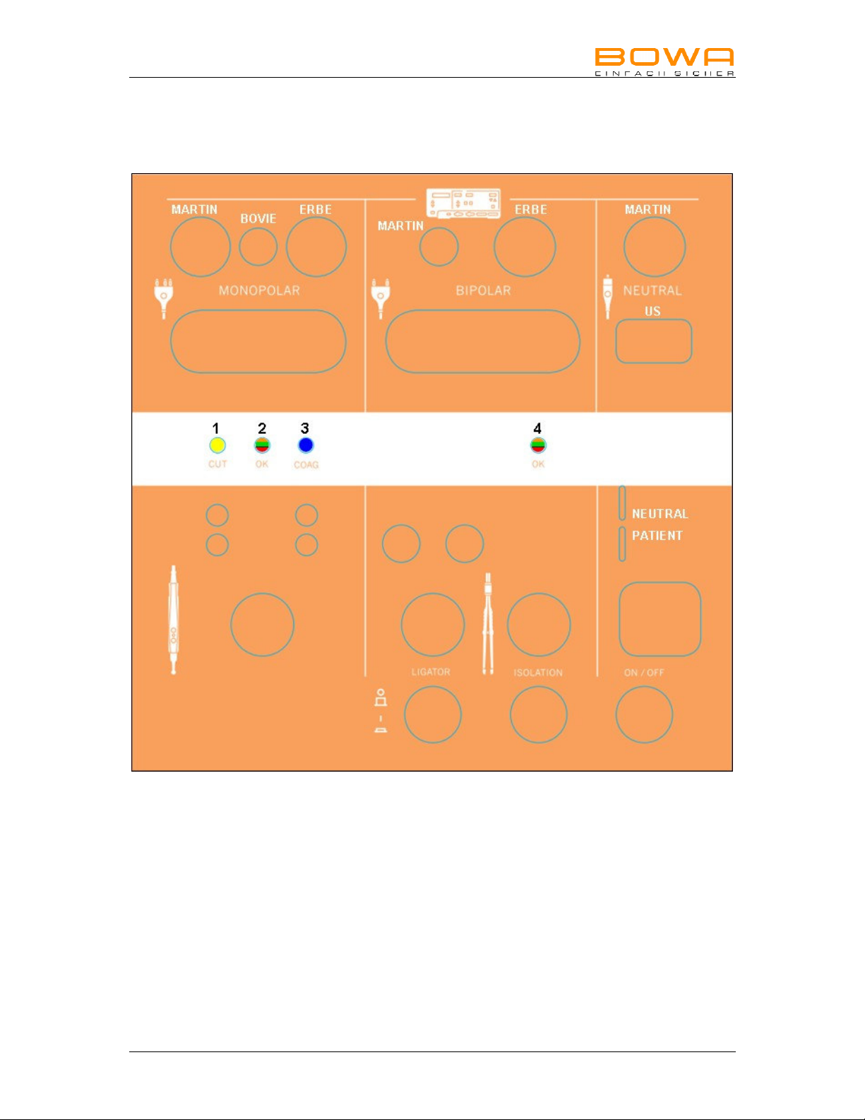
1. Connection Positions
MN030-423-IFU-M098-050230-S2-20100401 Testing Device Page 3
Page 14

2. Intended Use
The testing device is designed for testing monopolar handles as well as monopolar
and bipolar handles and cables with a Valleylab, ERBE or Martin-compatible
connection.
3. Operation
3.1 Switching on and functional test
• Connect the adapter to the low-voltage socket with a ‘push and turn’ bayonet
fitting.
• Plug the adapter into a locally provided socket; 100-240V AC possible.
• Press the On / Off switch
A visible switch-on test is executed:
All the LEDs illuminate
The Ligator and the Insulation switch flash alternately,
the status indicator LEDs subsequently illuminate from left to right
1 2 3 4
Yellow – Green – Blue – Red
Yellow – Red – Blue – Green
The dummy resistance is activated in the circuit in order to test the sensor and
operational amplifier.
- Orange - Orange
• The switch-on test and the simulation test have been successfully completed
when the status indicators 2 and 4 illuminate orange.
The cable testing device is now ready for operation.
- or -
An error is indicated by the status indicator 4 flashing orange / red.
Please contact the Technical Service Center (see section “5.1 Technical
Service Center”).
Caution:
Due to technical-measurement reasons, only one test item can be inserted at a
time!
Page 4 Testing Device MN030-423-IFU-M098-050230-S2-20100401
Page 15

3.2 Testing neutral electrode connecting cables
Test the various neutral electrode cables (right-hand side of the cable testing device).
Select the appropriate plug-in mount for your cable; then connect the device side and
subsequently the instrument side.
Status indicator “4” illuminates green if the test item is ok. The test item should now
be moved back and forth to test whether there is a defective contact or not. The
Insulation switch starts to flash at the same time. This means that the respective
switch must be pressed to initiate the insulation test.
If the cable is ok, the status indicator “4” illuminates green; the test item should also
be moved back and forth. Subsequently remove the test item.
If the test item is not ok, the status indicator “4” illuminates red. In this case, remove
the test item and mark it accordingly.
3.3 Testing bipolar connecting cables
Select the appropriate plug-in mount for your cable. Then proceed as described for
the neutral electrode cables.
3.4 Testing Ligator connecting cables
Set the Ligator switch to “ON”.
Select the appropriate plug-in mount for your cable; then connect the device side and
subsequently the instrument side.
The status indicator “4” illuminates green if the test item is ok. The test item should
now be moved back and forth to test whether there is a defective contact or not. The
insulation switch starts to flash at the same time. This means that the respective
switch must be pressed to initiate the insulation test.
If the cable is ok, the status indicator “4” illuminates green; the test item should also
be moved back and forth. Subsequently remove the test item.
If the test item is not ok, the status indicator “4” illuminates red or remains orange. In
this case, remove the test item and mark it accordingly.
MN030-423-IFU-M098-050230-S2-20100401 Testing Device Page 5
Page 16
3.5 Testing unipolar connecting cables
Select the appropriate plug-in mount on the left-hand side of the testing device for
your cable; then connect the device side and subsequently the instrument side.
The status indicator “2” illuminates green if the test item is ok. The test item should
now be moved back and forth to test whether there is a defective contact or not.
If the cable is not ok, the status indicator “2” flashes red. In this case, remove the
test item and mark it accordingly.
3.6 Testing handles with finger switches
Select the appropriate plug-in mount on the left-hand side of the testing device for
your cable; then connect the device side. Then insert the handle into the provided
horizontal contact pin. The status indicator “2” must illuminate green. Move the cable
back and forth, the status indicator “2” must continuously illuminate green.
If the cable is not ok, the status indicator “2” flashes red. In this case, remove the
test item and mark it accordingly.
Press the yellow key for Cut. The status indicator “1” must illuminate yellow.
If the key is not ok, the status indicator “2” flashes red or there is no reaction at all.
In this case, remove the test item and mark it accordingly.
Press the blue key for COAG. The status indicator “3” must illuminate blue.
If the key is not ok, the status indicator “2” flashes red or there is no reaction at all.
In this case, remove the test item and mark it accordingly.
3.7 Testing pedal foot switches
Select the socket located on the front of the testing device. Connect the foot switch.
Operate the pedals one after the other. The status indicator illuminates according to
the pedal color. The status indicator “2” is for the third pedal and changes from
orange to green.
If the pedal switch is not ok, the indicators do not react or illuminate; the status
indicator “2” remains orange. In this case, remove the test item and mark it
accordingly.
Page 6 Testing Device MN030-423-IFU-M098-050230-S2-20100401
Page 17

4. Disinfecting and Cleaning
Note
Incorrect handling of the testing device may result in damage!
Never sterilize the testing device. Always clean or disinfect it instead.
Warning
Risk of electric shock and fire!
Always disconnect the power plug prior to cleaning.
When cleaning surfaces, only use cleaning agents/disinfectants approved by the
manufacturer.
Make sure that liquid does not enter the device.
Cleaning
Use a damp cloth and mild cleaning agent to clean the casing. Never use abrasive
cleaning agents or solvents. Dirt and/or moisture in the connections can have a
negative effect on testing.
5. Maintenance/Repairs
Note
To prevent damages, do not attempt repairs or modifications to the testing
device yourself!
If repairs are necessary, contact the Technical Service Center specified below.
Never attempt repairs to the device yourself.
BOWA will be liable for the safety, reliability and performance of the testing device
under the following conditions:
• All the instructions regarding installation as well as correct and intended
usage contained in this operating manual have been followed precisely.
• Modifications, repairs, new settings, etc. have been carried out by BOWA
authorized service technicians.
• Electrical installations in the relevant room meet local requirements and
statutory provisions.
5.1 Technical Service Center
Contact the following Technical Service Center for maintenance and repair work:
BOWA-electronic GmbH & Co. KG
Heinrich-Hertz-Strasse 4–10
72810 Gomaringen, Germany
Phone +49 (0) 7072-6002-0
Fax +49 (0) 7072-6002-33
or visit our website:
www.bowa-medical.com
MN030-423-IFU-M098-050230-S2-20100401 Testing Device Page 7
Page 18

6. Disposal
At the end of its service life, the device can be disposed of as normal electrical and
electronic equipment waste. The disposal of the testing device, packaging material
and accessories must be in accordance with relevant country-specific regulations
and laws.
7. Technical Data and Version
Adapter: 100 VAC – 240 AC, 50 / 60Hz
Input current 400mA
Voltage regulated, current limited
Leakage current < 10uA
Rated voltage: 15 V DC
Rated current: 0.5 A DC
Frequency MCU: 16 MHz
Frequency handle: 20 kHz
Frequency cable measurement: 5 to 20 Hz
Internal interface: RS232
Test criteria: Connecting cable resistance < 10 Ohms
Status indicators: Orange (both status indicators) = ready for operation
Casing: Plastic with feet for console position.
Storage conditions:
Ambient conditions:
Insulation / Classification:
Compliance with standards DIN EN 61010:2002 + A1:2002 + A2:2004
EMC DIN EN 61326-1:2006
Protection rating II
Replaceable primary adapter
Handle keys < 220 Ohms
Active cable handle < 20 Ohms
Insulation resistance conductor to conductor > 1 mOhms
Measured from the instrument side,
Ligator connection cable according to specifications
Green (continuously) = test IS OK
Yellow = CUT – key pressed
Blue = COAG – key pressed
Red / No reaction = ERROR
Dimensions: W 240 x D 198 x H 110 mm
Weight: 1.5 kg
Temperature Rel. humidity
Atmospheric
pressure
-20 °C to +70 °C 10 - 100% 500 - 1060 hPa
-10 °C to +60 °C 10 - 100% 800 - 1060 hPa
Page 8 Testing Device MN030-423-IFU-M098-050230-S2-20100401
Page 19

8. Notes
MN030-423-IFU-M098-050230-S2-20100401 Testing Device Page 9
Page 20
CE Mark in accordance with
Directive 2006/95/EC
BOWA-electronic GmbH & Co. KG
Heinrich-Hertz-Straße 4-10
D-72810 Gomaringen │ Germany
Technical details subject to change! MADE IN GERMANY
050-230-IFU-V1.0-MN030-423-S2-20100401
Page 21

Mode d’emploi
Testeur pour
manches de bistouri et câbles
050-230
MN030-423-IFU-M098-050230-S2-20100401 03/10
Page 22

Table des matières
1. Emplacement des connexions 3
2. Conditions prévues d’utilisation 4
3. Manipulation 4
3.1 Activation et test de fonctionnalité 4
3.2 Contrôle des câbles de raccordement d’électrodes neutres 5
3.3 Contrôle des câbles de raccordement bipolaires 5
3.4 Contrôle des câbles de raccordement du Ligator 5
3.5 Contrôle des câbles de raccordement monopolaires 6
3.6 Contrôle de manches à boutons 6
3.7 Contrôle d’interrupteurs à pied 6
4. Nettoyage et désinfection 7
5. Maintenance/Réparation 7
5.1 Service technique 7
6. Mise au rebut 8
7. Données techniques et modèle 8
8. Notes 9
Page 2 Testeur MN030-423-IFU-M098-050230-S2-20100401
Page 23
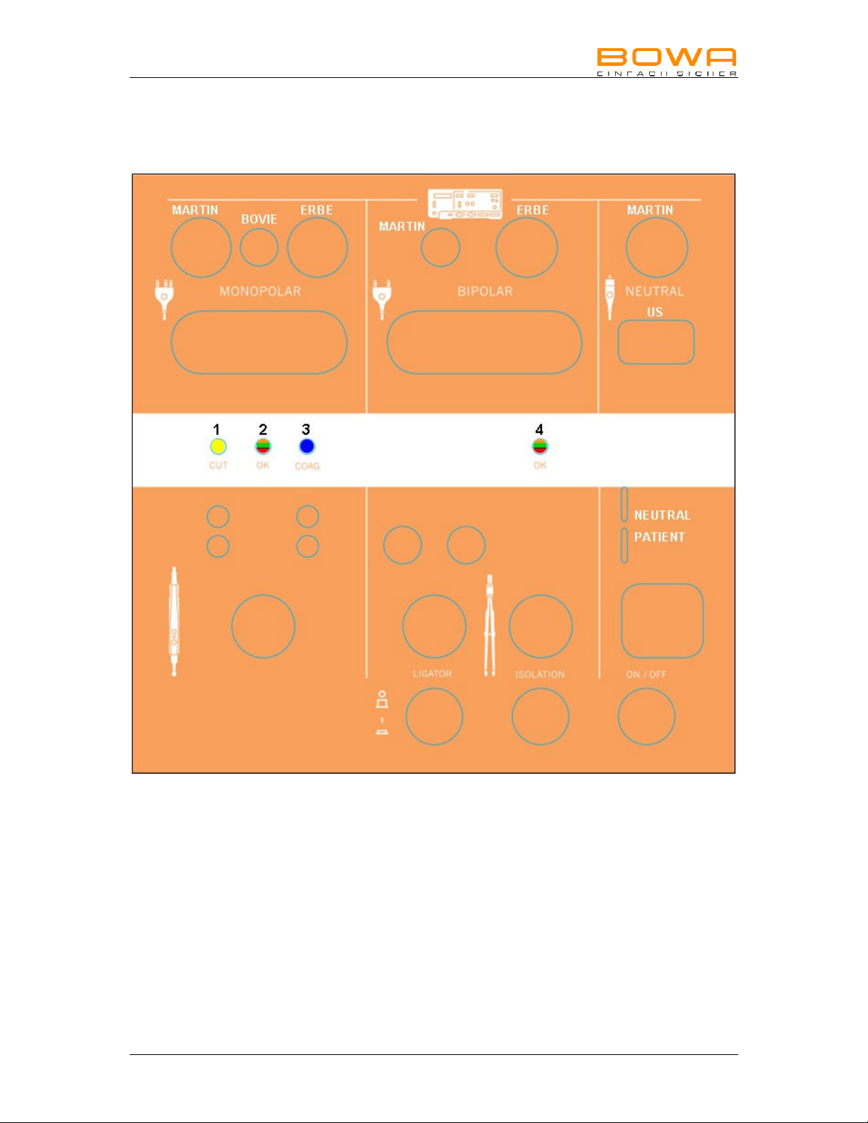
1. Emplacement des connexions
MN030-423-IFU-M098-050230-S2-20100401 Testeur Page 3
Page 24

2. Conditions prévues d’utilisation
Le testeur sert au contrôle de manches de bistouri monopolaires ainsi que de
manches de bistouri monopolaires/bipolaires et de leurs câbles destinés à être
utilisés avec des générateurs Valleylab, ERBE ou Martin.
3. Manipulation
3.1 Activation et test de fonctionnalité
• Connectez le bloc secteur à la prise à baïonnette basse tension en effectuant une
courte rotation.
• Raccordez le bloc secteur à la prise de courant présente sur le site – CA 100240 V admis.
• Actionnez l’interrupteur Marche/Arrêt
Un test d’activation visible est effectué :
Toutes les DEL s’allument
Les commutateurs de l’instrument Ligator et d’isolement clignotent en
alternance
Les témoins lumineux de statut s’allument ensuite de gauche à droite
1 2 3 4
Jaune – vert – bleu – rouge
Jaune – rouge – bleu – vert
La résistance d’essai est intégrée dans le circuit électrique afin que le
détecteur et l’AOP soient testés
- orange - orange
• Si les témoins de statut 2 et 4 brillent d’une lumière orange, le test d’activation et
de simulation a été effectué avec succès.
Le testeur de câbles est opérationnel.
- ou -
Si le témoin de statut 4 brille d’une lumière orange / rouge, une anomalie est
constatée.
Veuillez contacter le service technique (consultez le chapitre « 5.1 Service
technique »).
Attention :
Pour des raisons de technique de mesurage, un seul instrument peut être testé
à la fois !
Page 4 Testeur MN030-423-IFU-M098-050230-S2-20100401
Page 25
3.2 Contrôle des câbles de raccordement d’électrodes neutres
Contrôle des différents câbles d’électrodes neutres (partie droite du testeur)
Choisissez la connexion correspondant à votre câble ; raccordez tout d’abord
l’appareil, puis l’instrument.
Si la pièce testée est en bon état, l’indicateur de statut « 4 » brille d’une lumière
verte. Elle doit maintenant être mise en mouvement afin que le testeur puisse
déterminer un éventuel mauvais contact. Parallèlement, le commutateur d’isolement
se met à clignoter : le commutateur correspondant doit alors être actionné afin que
soit effectué le contrôle d’isolement.
Si le câble ne pose aucun problème, l’indicateur « 4 » brille d’une lumière verte – ici
aussi, la pièce testée doit être mise en mouvement. Déconnectez ensuite cette
dernière.
Si une anomalie est à constater, l’indicateur « 4 » brille d’une lumière rouge. La
pièce testée est alors à déconnecter et à identifier en conséquence.
3.3 Contrôle des câbles de raccordement bipolaires
Choisissez la connexion correspondant à votre câble. Procédez ensuite de la même
manière que pour les câbles des électrodes neutres.
3.4 Contrôle des câbles de raccordement du Ligator
Activez le commutateur portant le terme « Ligator ».
Choisissez la connexion correspondant à votre câble ; raccordez tout d’abord
l’appareil, puis l’instrument.
Si la pièce testée est en bon état, l’indicateur de statut « 4 » brille d’une lumière
verte. Elle doit maintenant être mise en mouvement afin que le testeur puisse
déterminer un éventuel mauvais contact. Parallèlement, le commutateur d’isolement
se met à clignoter : le commutateur correspondant doit alors être actionné afin que
soit effectué le contrôle d’isolement.
Si le câble ne pose aucun problème, l’indicateur « 4 » brille d’une lumière verte – ici
aussi, la pièce testée doit être mise en mouvement. Déconnectez ensuite cette
dernière.
Si une anomalie est à constater, l’indicateur « 4 » brille d’une lumière rouge ou reste
orange. La pièce testée est alors à déconnecter et à identifier en conséquence.
MN030-423-IFU-M098-050230-S2-20100401 Testeur Page 5
Page 26
3.5 Contrôle des câbles de raccordement monopolaires
Choisissez la connexion correspondant à votre câble (partie gauche du testeur) ;
raccordez tout d’abord l’appareil, puis l’instrument.
Si la pièce testée est en bon état, l’indicateur de statut « 2 » brille d’une lumière
verte. Elle doit maintenant être mise en mouvement afin que le testeur puisse
déterminer un éventuel mauvais contact.
Si une anomalie est à constater sur le câble, l’indicateur « 2 » clignote d’une lumière
rouge. La pièce testée est alors à déconnecter et à identifier en conséquence.
3.6 Contrôle de manches à boutons
Choisissez la connexion correspondant à votre câble (partie gauche du testeur) ;
raccordez tout d’abord l’appareil. Branchez le manche au connecteur mâle horizontal
prévu à cet effet. L’indicateur de statut « 2 » doit alors se mettre à briller d’une
lumière verte. Mettez le câble en mouvement, l’indicateur « 2 » doit briller en
permanence d’une lumière verte.
Si une anomalie est à constater sur le câble, l’indicateur « 2 » clignote d’une lumière
rouge. La pièce testée est alors à déconnecter et à identifier en conséquence.
Activez la touche jaune de Coupe (Cut). L’indicateur de statut « 1 » doit se mettre à
briller d’une lumière jaune.
Si une anomalie est à constater pour cette touche, l’indicateur « 2 » clignote d’une
lumière rouge ou ne réagit pas. La pièce testée est alors à déconnecter et à identifier
en conséquence.
Activez la touche bleue de Coagulation (COAG). L’indicateur de statut « 3 » doit se
mettre à briller d’une lumière bleue.
Si une anomalie est à constater pour cette touche, l’indicateur « 2 » clignote d’une
lumière rouge ou ne réagit pas. La pièce testée est alors à déconnecter et à identifier
en conséquence.
3.7 Contrôle d’interrupteurs à pied
Utilisez la prise située sur la face avant du testeur. Connectez l’interrupteur à pied.
Activez les pédales successivement. L’indicateur de statut brillera alors selon la
couleur de la pédale. L’indicateur « 2 » est destiné à la troisième pédale et brille
d’une couleur orange puis verte alternativement.
Si l’interrupteur à pied présente une anomalie, les indicateurs ne réagissent ni ne
brillent et l’indicateur « 2 » reste orange. La pièce testée est alors à déconnecter et à
identifier en conséquence.
Page 6 Testeur MN030-423-IFU-M098-050230-S2-20100401
Page 27
4. Nettoyage et désinfection
Indication
Endommagement du testeur dû à une manipulation inappropriée !
Ne stérilisez jamais le testeur. Il doit être nettoyé et désinfecté.
Avertissement
Risque de choc électrique et d’incendie !
Débranchez l’appareil avant le nettoyage.
Nettoyez les surfaces uniquement avec des produits nettoyants/désinfectants
autorisés en respectant impérativement les consignes du fabricant.
Assurez-vous qu’aucun liquide ne pénètre dans l’appareil.
Nettoyage
Utilisez un chiffon légèrement humide et un nettoyant doux pour nettoyer le boîtier du
testeur. Ne procédez jamais au nettoyage avec un produit abrasif ou un solvant.
La présence de crasse et/ou d’humidité sur les connexions est susceptible de gêner
le contrôle.
5. Maintenance/Réparation
Indication
Endommagement du testeur suite à des réparations ou à des modifications
effectuées de votre propre initiative !
Si une réparation est requise, veuillez vous adresser exclusivement au support
technique dont l’adresse est indiquée ci-dessous.
N’effectuez en aucun cas de réparation de votre propre initiative.
BOWA assume la responsabilité quant au fonctionnement en toute sécurité, à la
fiabilité et aux performances du testeur sous les conditions suivantes :
• Toutes les instructions concernant l’installation et l’utilisation conforme à la
destination d’usage énoncées dans ce manuel d’utilisation ont été
scrupuleusement respectées.
• Les modifications, les réparations et les nouveaux réglages ont été
effectués uniquement par des personnes autorisées par BOWA pour
l’exécution de ces travaux.
• Les installations électriques du site concerné répondent à la législation
locale et aux dispositions juridiques.
5.1 Service technique
Pour tous travaux de maintenance et de réparation, adressez-vous à notre service
d’assistance technique à l’adresse suivante :
BOWA-electronic GmbH & Co. KG
Heinrich-Hertz-Strasse 4–10
72810 Gomaringen/Allemagne
Téléphone +49 (0) 7072-6002-0
Téléfax +49(0) 7072/-6002-33
ou visitez notre site :
www.bowa-medical.com
MN030-423-IFU-M098-050230-S2-20100401 Testeur Page 7
Page 28

6. Mise au rebut
Sa durée de vie utile une fois écoulée, l’appareil est à éliminer conformément aux
dispositions en vigueur en matière de déchets électroniques. La mise au rebut du
testeur, du matériel d’emballage et des instruments doit impérativement être
effectuée dans le respect des règlements et des lois propres au pays d’utilisation.
7. Données techniques et modèle
Bloc secteur : 100 V CA – 240 V CA, 50 / 60Hz
Courant d’entrée 400 mA
Tension régulée, courant limité
Courant de fuite < 10uA
Fiches secteurs interchangeables
Tension nominale : 15 volts CC
Courant nominal : 0,5 A CC
Fréquence MCU : 16 MHz
Fréquence manche : 20 kHz
Fréquence mesurage cable : de 5 à 20 Hz
Interface interne : RS232
Critères de test : Résistance câble de raccordement < 10 ohms
Touches du manche < 220 ohms
Câble activé du manche < 20 ohms
Résistance diélectrique câble à câble > 1 Mohm
Mesuré sur l’instrument,
câble de raccordement du Ligator selon les spécifications
Indic. de statut : orange (les 2 indic. de statut) = Opérationnel
vert (constant) = pièce testée OK
jaune = CUT – touche activée
bleu = COAG – touche activée
rouge / aucune réaction = ANOMALIE
Boîtier : Matière synthétique avec pieds support.
Dimensions : L 240 x P 198 x H 110 mm
Poids : 1,5 kg
Conditions de stockage :
Conditions ambiantes :
Isolement / Classification :
Conformité aux normes DIN EN 61010:2002 + A1:2002 + A2:2004
Compatibilité électromagnétique DIN EN 61326-1:2006
Classe de protection II
Température Humidité relative Pression atm.
-20 °C à +70 °C 10 - 100% 500 - 1 060 hPa
-10 °C à +60 °C 10 - 100% 800 - 1 060 hPa
Page 8 Testeur MN030-423-IFU-M098-050230-S2-20100401
Page 29

8. Notes
MN030-423-IFU-M098-050230-S2-20100401 Testeur Page 9
Page 30
Marquage CE conformément à
la directive 2006/95/CE
BOWA-electronic GmbH & Co. KG
Heinrich-Hertz-Strasse 4-10
D-72810 Gomaringen │ Allemagne
Téléphone +49 (0) 7072 / 6002 - 0
Téléfax +49 (0) 7072 / 6002 - 33
[email protected] │ bowa-medical.com
Sous réserve de modification technique. FABRIQUÉ EN ALLEMAGNE
050-230-IFU-V1.0-MN030-423-S2-20100401
Page 31

Instrucciones de uso
Comprobador para
Mangos de electrodos y Cables
050-230
MN030-423-IFU-M098-050230-S2-20100401 03/10
Page 32

Contenido
1. Posiciones de conexión 3
2. Uso conforme a lo prescrito 4
3. Mando 4
3.1 Encender y hacer la prueba de funcionamiento 4
3.2 Revisar los cables de conexión de electrodos neutros 5
3.3 Revisar los cables de conexión bipolares 5
3.4 Revisar los cables de conexión del Ligator 5
3.5 Revisar los cables de conexión molopolares 6
3.6 Revisar de mangos con interruptores digitales 6
3.7 Comprobación de interruptores de pedal 6
4. Desinfectar y limpiar 7
5. Mantenimiento/Reparación 7
5.1 Servicio técnico 7
6. Eliminación 8
7. Datos técnicos y modelo 8
8. Notas 9
Página 2 Comprobador MN030-423-IFU-M098-050230-S2-20100401
Page 33
1. Posiciones de conexión
MN030-423-IFU-M098-050230-S2-20100401 Comprobador Página 3
Page 34
2. Uso conforme a lo prescrito
El comprobador sirve para comprobar mangos monopolares, mangos mono y
bipolares y cables con conexión compatible con Valleylab, ERBE o Martin.
3. Mando
3.1 Encender y hacer la prueba de funcionamiento
• Conectar el transformador de enchufe en la clavija de tensión baja con cierre de
bayoneta efectuando un breve giro.
• Es posible conectar el transformador de enchufe en la caja de enchufe a cargo
del propietario con 100-240V AC.
• Pulsar el conectador / desconectador
Resulta una prueba de conexión visible:
Se encienden todos los LEDs
El interruptor Ligator y el de aislamiento parpadean recíprocamente
Luego se encienden los LEDs de indicación de estado de izquierda a derecha
1 2 3 4
Amarillo – verde – azul – rojo
Amarillo – rojo – azul – verde
Se conmuta la resistencia ficticia en el circuito de conmutación para probar el
sensor y el amplificador operacional
- naranja - naranja
• Si los indicadores 2 y 4 alumbran de color naranja, se ha concluido con éxito la
prueba de conexión y de simulación.
El comprobador de cables está listo para el servicio.
–o bien–
Si el indicador de estado 4 naranja / rojo parpadea, entonces hay un error.
Por favor diríjase al servicio técnico (véase el capítulo “5.1 Servicio técnico“).
Atención:
¡Por razones de técnica de medición debe estar enchufada sólo una pieza de
ensayo!
Página 4 Comprobador MN030-423-IFU-M098-050230-S2-20100401
Page 35

3.2 Revisar los cables de conexión de electrodos neutros
Revisar los diferentes cables de electrodos neutros (lado derecho del comprobador
de cables)
Elija para su cable el enchufe adecuado y adapte primero el lado del aparato,
después el lado de los instrumentos.
El indicador de estado “4“ se encenderá con una buena pieza de ensayo. Ahora, la
pieza de ensayo deberá ser agitada para ver si hay algún contacto flojo. Al mismo
tiempo, el interruptor de aislamiento empezará a parpadear. Esto significa que deben
ser pulsados los interruptores correspondientes para realizar las pruebas de
aislamiento.
Si el cable está en orden, entonces el indicador de estado “4“ alumbrará en verde;
aquí también deberá moverse en vaivén la pieza de ensayo. A continuación, alejar la
pieza de ensayo.
Si la pieza de ensayo no está en orden, el indicador de estado “4“ alumbrará en
rojo. En este caso, alejar la pieza de ensayo y marcarla correspondientemente.
3.3 Revisar los cables de conexión bipolares
Elija para su cable el enchufe adecuado. A continuación, proceda del mismo modo
como con los cables de electrodo neutro.
3.4 Revisar los cables de conexión del Ligator
Conecte el interruptor denominado Ligator.
Elija para su cable el enchufe adecuado y adapte primero el lado del aparato,
después el lado de los instrumentos.
El indicador de estado “4“ se encenderá con una buena pieza de ensayo. Ahora, la
pieza de ensayo deberá ser movida en vaivén para ver si hay algún contacto flojo. Al
mismo tiempo, el interruptor de aislamiento empezará a parpadear. Esto significa
que deberá ser pulsado el interruptor correspondiente para realizar la prueba de
aislamiento.
Si el cable está en orden, entonces el indicador de estado “4“ alumbrará en verde;
aquí también deberá moverse en vaivén la pieza de ensayo. A continuación, alejar la
pieza de ensayo.
Si la pieza de ensayo no está en orden, el indicador de estado “4“ alumbrará en rojo
o permanecerá en color naranja. En este caso, alejar la pieza de ensayo y marcarla
correspondientemente.
MN030-423-IFU-M098-050230-S2-20100401 Comprobador Página 5
Page 36
3.5 Revisar los cables de conexión molopolares
Elija para su cable el enchufe adecuado en el lado izquierdo y adapte primero el lado
del comprobador, después el lado de los instrumentos.
El indicador de estado “2“ alumbrará en verde si se presenta una buena pieza de
ensayo; ahora, la pieza de ensayo deberá ser movida en vaivén para comprobar si
eventualmente existe un contacto flojo.
Si el cable no está en orden, el indicador de estado “2“ parpadeará en rojo. En este
caso, alejar la pieza de ensayo y marcarla correspondientemente.
3.6 Revisar de mangos con interruptores digitales
Elija para su cable el enchufe adecuado en el lado izquierdo y adapte primero el lado
del aparato. A continuación, enchufe usted el mango en la clavija de contacto
horizontal prevista para ello. A continuación, el indicador de estado “2“ deberá
alumbrar en verde. Mueva en vaivén el cable; el indicador de estado “2“ deberá
alumbrar permanentemente en verde.
Si el cable no está en orden, el indicador de estado “2“ parpadeará en rojo. En este
caso, alejar la pieza de ensayo y marcarla correspondientemente.
Pulse la tecla amarilla para Cut (corte). A continuación, el indicador de estado “1“
deberá alumbrar en amarillo.
Si el cable no está en orden, el indicador de estado “2“ parpadeará en rojo o no
mostrará ninguna reacción. En este caso, alejar la pieza de ensayo y marcarla
correspondientemente.
Pulse la tecla azul para COAG. El indicador de estado “3“ deberá alumbrar en azul.
Si el cable no está en orden, el indicador de estado “2“ parpadeará en rojo o no
mostrará ninguna reacción. En este caso, alejar la pieza de ensayo y marcarla
correspondientemente.
3.7 Comprobación de interruptores de pedal
Elija la clavija en la cara frontal del comprobador. Adapte el interruptor de pedal.
Opere los pedales sucesivamente. El indicador de estado alumbrará conforme al
color del pedal. El indicador de estado “2“ es para el tercer pedal y cambiará de
color naranja a verde.
Si el interruptor de pedal no está en orden, los indicadores no reaccionarán ni
alumbrarán; el indicador de estado “2“ permanecerá en color naranja. En este caso,
alejar la pieza de ensayo y marcarla correspondientemente.
Página 6 Comprobador MN030-423-IFU-M098-050230-S2-20100401
Page 37

4. Desinfectar y limpiar
Nota
¡El uso incorrecto puede dañar el comprobador!
Nunca esterilice el comprobador. Límpielo o desinféctelo.
Aviso
¡Peligro de descargas eléctricas y de incendio!
Desenchufe de la red antes de limpiarlo.
Utilice únicamente productos de limpieza o desinfección admisibles para la
limpieza de superficies sólo según las instrucciones del fabricante.
Asegúrese de que no pueda penetrar ningún líquido en el aparato.
Limpieza
Limpiar la carcasa con un paño húmedo y un detergente suave. No utilizar ningún
limpiador abrasivo o disolvente para la limpieza. Cualquier suciedad y/o humedad en
las conexiones puede menoscabar los ensayos.
5. Mantenimiento/Reparación
Nota
¡Daño del comprobador debido a medidas de reparación y modificaciones
realizadas de propia mano!
Cuando sea necesaria una reparación, diríjase únicamente a la dirección de
servicio técnico que se indica más abajo.
No realice nunca las reparaciones usted mismo.
BOWA asume la responsabilidad sobre la seguridad, el funcionamiento y
rendimiento del comprobador bajo las siguientes condiciones:
• Cumplimiento exacto de todas las instrucciones relativas a la instalación y
el uso correcto según estas instrucciones de uso.
• Realización de cambios, reparaciones, reajustes, etc. únicamente por parte
de personas autorizadas por BOWA para ejecutar esos trabajos.
• Cumplimiento de la normativa local y las disposiciones legales respectivas
en las instalaciones eléctricas en la sala de trabajo correspondiente.
5.1 Servicio técnico
Para el mantenimiento o la reparación, diríjase a la siguiente dirección de servicio
técnico:
BOWA-electronic GmbH & Co. KG
Heinrich-Hertz-Strasse 4–10
72810 Gomaringen/Germany
Teléfono +49 (0) 7072-6002-0
Telefax +49 (0) 7072-6002-33
o bien en Internet en:
www.bowa-medical.com
MN030-423-IFU-M098-050230-S2-20100401 Comprobador Página 7
Page 38

6. Eliminación
Al final de su vida útil, el aparato podrá ser eliminado como chatarra electrónica
común y corriente. La eliminación del comprobador, del material de embalaje y de
los accesorios deberá efectuarse de acuerdo con la legislación y la normativa
específica vigente en el país de uso.
7. Datos técnicos y modelo
Transformador de enchufe: 100 VAC – 240 AC, 50 / 60Hz
Corriente de entrada 400mA
Regulado por tensión, limitado de corriente
Corriente de fuga < 10uA
Tensión nominal: 15 voltios DC
Corriente nominal: 0,5 A DC
Frecuencia del MCU: 16 MHz
Frecuencia del mango: 20 kHz
Frecuencia de medición de cable: de 5 a 20 Hz
Interfaz interna: RS232
Criterios de ensayo: Resistencia de cables de conexión < 10 ohmios
Teclas de mango < 220 ohmios
Cable activo de mango < 20 ohmios
Resistencia de aislamiento de conductor > 1 Mohmio
Medido del lado del instrumento,
Cable de conexión de Ligator según especificación
Indicaciones de estado:
naranja (ambas indicaciones de estado) = Listo para el servicio
verde (permanente) = Pieza de prueba EN ORDEN
amarillo = CUT – Tecla pulsada
azul = COAG – Tecla pulsada
rojo / ninguna reacción = ERROR
Carcasa: Plástico con pies de montaje para el pupitre.
Dimensiones: Ancho 240 x profundidad 198 x alto 110 mm
Peso: 1,5 kg
Temperatura Humedad relativa Presión del aire
Condiciones de
almacenamiento:
Condiciones
externas:
de -20 °C a +70 °C 10 - 100% 500 - 1060 hPa
de -10 °C a +60 °C 10 - 100% 800 - 1060 hPa
Aislamiento / Clasificación:
Conformidad con las normas DIN EN 61010:2002 + A1:2002 + A2:2004
CEM DIN EN 61326-1:2006
Clase de protección II
Adaptador primario intercambiable
Página 8 Comprobador MN030-423-IFU-M098-050230-S2-20100401
Page 39

8. Notas
MN030-423-IFU-M098-050230-S2-20100401 Comprobador Página 9
Page 40
Caracterización CE conforme
a la Directiva 2006/95/CE
BOWA-electronic GmbH & Co. KG
Heinrich-Hertz-Straße 4-10
D-72810 Gomaringen │ Germany
Teléfono +49 (0) 7072 / 6002 - 0
Telefax +49 (0) 7072 / 6002 - 33
[email protected] │ bowa-medical.com
Salvo modificaciones técnicas. MADE IN GERMANY
050-230-IFU-V1.0-MN030-423-S2-20100401
Page 41

Istruzioni per l’uso
Apparecchio di prova per
manipoli degli elettrodi e cavi
050-230
MN030-423-IFU-M098-050230-S2-20100401 03/10
Page 42

Contenuto
1. Posizioni di collegamento 3
2. Utilizzo corretto 4
3. Utilizzo 4
3.1 Accensione e test funzionale 4
3.2 Verifica dei cavi di collegamento degli elettrodi neutri 5
3.3 Verifica dei cavi di collegamento bipolari 5
3.4 Verifica dei cavi di collegamento LIGATOR 5
3.5 Verifica dei cavi di collegamento monopolari 6
3.6 Verifica di manipoli con interruttori manuali 6
3.7 Verifica dei comandi a pedale 6
4. Disinfezione e pulizia 7
5. Manutenzione/Riparazione 7
5.1 Assistenza tecnica 7
6. Smaltimento 8
7. Dati tecnici ed esecuzione 8
8. Appunti 9
Pagina 2 Apparecchio di prova 050-230-IFU-V1.0-MN030-423-S2-20100401
Page 43
1. Posizioni di collegamento
MN030-423-IFU-M098-050230-S2-20100401 Apparecchio di prova Pagina 3
Page 44

2. Utilizzo corretto
L’apparecchio di prova è concepito per la verifica di manipoli monopolari, nonché di
manipoli monopolari e bipolari e di cavi con attacco compatibile con Valleylab, ERBE
o Martin.
3. Utilizzo
3.1 Accensione e test funzionale
• Collegare l’adattatore alla presa a bassa tensione con attacco a baionetta, quindi
ruotarlo.
• Inserire l’adattatore in una presa presente in loco (100-240 V CA possibile).
• Premere l’interruttore ON/OFF.
Si avvia una prova di accensione visibile:
Tutti i LED si accendono
Gli interruttori LIGATOR e ISOLATION lampeggiano alternativamente
In seguito gli indicatori di stato a LED si illuminano da sinistra verso destra
1 2 3 4
giallo – verde – blu – rosso
giallo – rosso – blu – verde
Nel circuito viene attivata una resistenza fittizia per la verifica del sensore e
dell’amplificatore operazionale
- arancione - arancione
• Se si accendono gli indicatori di stato 2 e 4, la prova di accensione e quella di
simulazione si sono concluse correttamente.
Il tester per cavi è pronto per l’uso.
- oppure -
Se l’indicatore di stato 4 lampeggia con luce arancione/rossa si è verificato un
errore.
Rivolgersi all’Assistenza tecnica (vedere capitolo “5.1 Assistenza tecnica”).
Attenzione:
Per motivi legati alla tecnica di misurazione è necessario collegare sempre un
solo elemento da esaminare alla volta!
Pagina 4 Apparecchio di prova 050-230-IFU-V1.0-MN030-423-S2-20100401
Page 45

3.2 Verifica dei cavi di collegamento degli elettrodi neutri
Verifica dei diversi cavi degli elettrodi neutri (lato destro del tester per cavi).
Selezionare l’attacco adatto al proprio cavo, quindi connettere per prima cosa il lato
apparecchio, quindi il lato strumenti.
Se l’elemento da esaminare non presenta anomalie, l’indicatore di stato “4” si
accende con luce verde. A questo punto è necessario spostare avanti e indietro
l’elemento in esame per stabilire l’eventuale presenza di un contatto allentato.
Contemporaneamente l’interruttore ISOLATION inizia a lampeggiare. Ciò significa
che è necessario premerlo per effettuare una verifica dell’isolamento.
Se il cavo non presenta anomalie, l’indicatore di stato “4” si accende con luce verde;
anche in questo caso occorre spostare l’elemento da esaminare avanti e indietro.
Successivamente rimuovere tale elemento.
Se l’elemento in esame presenta anomalie, l’indicatore di stato “4” si accende con
luce rossa. In tal caso rimuovere l’elemento e contrassegnarlo in modo
corrispondente.
3.3 Verifica dei cavi di collegamento bipolari
Selezionare l’attacco adatto al proprio cavo. Procedere quindi come per i cavi degli
elettrodi neutri.
3.4 Verifica dei cavi di collegamento LIGATOR
Portare l’interruttore LIGATOR su “ON”.
Selezionare l’attacco adatto al proprio cavo, quindi connettere per prima cosa il lato
apparecchio, quindi il lato strumenti.
Se l’articolo da esaminare non presenta anomalie, l’indicatore di stato “4” si accende
con luce verde. A questo punto è necessario spostare l’elemento avanti e indietro per
individuare l’eventuale presenza di un contatto allentato. Contemporaneamente
l’interruttore ISOLATION inizia a lampeggiare. Ciò significa che è necessario
premerlo per effettuare una verifica dell’isolamento.
Se l’elemento da esaminare non presenta anomalie, l’indicatore di stato “4” si
accende con luce verde; anche in questo caso occorre spostare l’elemento avanti e
indietro. Successivamente rimuovere tale elemento.
Se l’elemento in esame presenta anomalie, l’indicatore di stato “4” si accende con
luce rossa oppure rimane arancione. In tal caso rimuovere l’elemento e
contrassegnarlo in modo corrispondente.
MN030-423-IFU-M098-050230-S2-20100401 Apparecchio di prova Pagina 5
Page 46
3.5 Verifica dei cavi di collegamento monopolari
Selezionare l’attacco adatto al proprio cavo sul lato sinistro dell’apparecchio di prova;
connettere per prima cosa il lato apparecchio, quindi il lato strumenti.
Se l’elemento da esaminare non presenta anomalie, l’indicatore di stato “2” si
accende con luce verde; spostare l’elemento avanti e indietro per individuare un
eventuale contatto allentato.
Se il cavo presenta anomalie, l’indicatore di stato “2” lampeggia con luce rossa. In
tal caso rimuovere l’elemento e contrassegnarlo in modo corrispondente.
3.6 Verifica di manipoli con interruttori manuali
Selezionare l’attacco adatto al proprio cavo sul lato sinistro dell’apparecchio di prova,
quindi connettere per prima cosa il lato apparecchio. Successivamente inserire il
manipolo nell’apposito pin di contatto orizzontale. L’indicatore di stato “2” deve
accendersi con luce verde. Spostare il cavo avanti e indietro; l’indicatore di stato “2”
deve rimanere costantemente acceso con luce verde.
Se il cavo presenta anomalie, l’indicatore di stato “2” lampeggia con luce rossa. In
tal caso rimuovere l’elemento e contrassegnarlo in modo corrispondente.
Premere il tasto giallo per la funzione “Cut”. L’indicatore di stato “1” deve accendersi
con luce gialla.
Se il tasto presenta anomalie l’indicatore di stato “2” lampeggia con luce rossa
oppure non risponde in alcun modo. In tal caso rimuovere l’elemento in esame e
contrassegnarlo in modo corrispondente.
Premere il tasto blu per la funzione “COAG”. L’indicatore di stato “3” deve
accendersi con luce blu.
Se il tasto presenta anomalie l’indicatore di stato “2” lampeggia con luce rossa
oppure non risponde in alcun modo. In tal caso rimuovere l’elemento in esame e
contrassegnarlo in modo corrispondente.
3.7 Verifica dei comandi a pedale
Scegliere la boccola sul lato frontale dell’apparecchio di prova e connettere il
comando a pedale.
Azionare i pedali in successione. L’indicatore di stato si illumina in base al colore del
pedale. L’indicatore di stato “2” si riferisce al terzo pedale e il suo colore passa
dall’arancione al verde.
Se il comando a pedale presenta anomalie, gli indicatori non rispondono in alcun
modo e non si accendono; l’indicatore di stato “2” rimane arancione. In tal caso
rimuovere l’elemento in esame e contrassegnarlo in modo corrispondente.
Pagina 6 Apparecchio di prova 050-230-IFU-V1.0-MN030-423-S2-20100401
Page 47

4. Disinfezione e pulizia
Avvertenza
Danneggiamento dell’apparecchio di prova in seguito a manipolazione errata!
L’apparecchio di prova non deve mai essere sterilizzato, bensì pulito o disinfettato.
Avvertimento
Pericolo di scossa elettrica e incendio!
Scollegare il connettore di rete prima della pulizia.
Per la pulizia delle superfici utilizzare detergenti/disinfettanti autorizzati,
rispettando le avvertenze del relativo produttore.
Assicurarsi che nell’apparecchio non penetri alcun liquido.
Pulizia
Pulire l’alloggiamento con un panno umido e con l’ausilio di un detergente non
aggressivo. Non impiegare detergenti abrasivi o solventi. L’eventuale presenza di
sporcizia e/o umidità nei collegamenti può compromettere le verifiche.
5. Manutenzione/Riparazione
Avvertenza
Danneggiamento dell’apparecchio di prova in seguito a riparazioni eseguite
autonomamente e a modifiche!
Se è necessaria una riparazione, rivolgersi esclusivamente al servizio di
assistenza indicato di seguito.
Non effettuare in alcun caso riparazioni in modo autonomo.
BOWA si assume la responsabilità per la sicurezza, l’affidabilità e la prestazione
dell’apparecchio di prova, previo rispetto delle condizioni seguenti:
• Tutte le indicazioni per l’installazione e l’utilizzo corretto di cui nelle presenti
istruzioni d’uso sono state seguite scrupolosamente.
• Modifiche, riparazioni, nuove regolazioni ecc. sono state effettuate solo da
persone autorizzate da BOWA all’esecuzione di tali interventi.
• Le installazioni elettriche nel locale di utilizzo sono conformi alle prescrizioni
e alle disposizioni di legge.
5.1 Assistenza tecnica
Per interventi di manutenzione e riparazione, rivolgersi al servizio di assistenza:
BOWA-electronic GmbH & Co. KG
Heinrich-Hertz-Strasse 4–10
72810 Gomaringen/Germany
Telefono +49 (0) 7072-6002-0
Fax +49 (0) 7072-6002-33
Oppure tramite Internet all’indirizzo:
www.bowa-medical.com
MN030-423-IFU-M098-050230-S2-20100401 Apparecchio di prova Pagina 7
Page 48

6. Smaltimento
Al termine della vita utile l’apparecchio deve essere smaltito come un normale rifiuto
elettronico. Lo smaltimento dell’apparecchio di prova, del materiale di imballaggio e
degli accessori deve avvenire in conformità alle disposizioni e alle leggi vigenti nei
paesi di utilizzo.
7. Dati tecnici ed esecuzione
Adattatore: 100 V CA – 240 CA, 50 / 60Hz
Corrente d’ingresso 400 mA
Tensione regolata, corrente limitata
Corrente di dispersione < 10 uA
Tensione nominale: 15 Volt CC
Corrente nominale: 0,5 A CC
Frequenza MCU: 16 MHz
Frequenza manipolo: 20 kHz
Frequenza misurazione cavi: da 5 a 20 Hz
Interfaccia interna: RS232
Criteri di verifica: Resistenza cavi di collegamento < 10 Ohm
Indicatori di stato: Arancione (entrambi gli indicatori di stato) = pronto per l’uso
Alloggiamento: Plastica con piedi di appoggio per il banco di manovra.
Condizioni di
conservazione:
Condizioni ambientali:
Isolamento / Classificazione:
Conformità alle norme DIN EN 61010:2002 + A1:2002 + A2:2004
Compatibilità elettromagnetica (CEM) DIN EN 61326-1:2006
Classe di protezione II
Adattatore primario sostituibile
Tasti manipolo < 220 Ohm
Cavo attivo manipolo < 20 Ohm
Resistenza isolamento da conduttore a conduttore > 1 MOhm
Misurazione a partire dal lato strumenti,
cavo di collegamento LIGATOR in base alla specifica
Verde (permanente) = elemento in esame OK
Giallo = tasto CUT premuto
Blu = tasto COAG premuto
Rosso / Nessuna reazione = ERRORE
Misure: L 240 x P 198 x A 110 mm
Peso: 1,5 kg
Temperatura Umidità relativa
da -20 °C a +70
°C
da -10 °C a +60
°C
10 - 100% 500 - 1060 hPa
10 - 100% 800 - 1060 hPa
Pressione
atmosferica
Pagina 8 Apparecchio di prova 050-230-IFU-V1.0-MN030-423-S2-20100401
Page 49

8. Appunti
MN030-423-IFU-M098-050230-S2-20100401 Apparecchio di prova Pagina 9
Page 50
Marchio CE secondo la
direttiva 2006/95/CE
BOWA-electronic GmbH & Co. KG
Heinrich-Hertz-Straße 4-10
D-72810 Gomaringen │ Germany
Con riserva di modifiche tecniche. MADE IN GERMANY
050-230-IFU-V1.0-MN030-423-S2-20100401
Page 51

Instrukcja obsługi
Przyrząd kontrolny do
uchwytów do elektrod i kabli
050-230
MN030-423-IFU-M098-050230-S2-20100401 03/10
Page 52

Spis treści
1. Pozycje podłączeń 3
2. Użytkowanie zgodne z przeznaczeniem 4
3. Obsługa 4
3.1 Włączenie i test działania 4
3.2 Kontrola przewodów przyłączeniowych elektrod neutralnych 5
3.3 Kontrola przewodów przyłączeniowych elektrod dwubiegunowych 5
3.4 Kontrola przewodów przyłączeniowych Ligatora 5
3.5 Kontrola przewodów przyłączeniowych jednobiegunowych 6
3.6 Sprawdzanie uchwytów z przełącznikami palcowymi 6
3.7 Sprawdzanie przełączników nożnych pedałowych 6
4. Dezynfekcja i czyszczenie 7
5. Konserwacja / naprawa 7
5.1 Serwis techniczny 7
6. Złomowanie 8
7. Dane techniczne i wersja 8
8. Notatki 9
Strona 2 Przyrząd kontrolny MN030-423-IFU-M098-050230-S2-20100401
Page 53
9. Pozycje podłączeń
MN030-423-IFU-M098-050230-S2-20100401 Przyrząd kontrolny Strona 3
Page 54

10. Użytkowanie zgodne z przeznaczeniem
Przyrząd kontrolny służy do kontroli jednobiegunowych uchwytów oraz jedno- i
dwubiegunowych uchwytów i kabli z końcówkami kompatybilnymi z Valleylab, ERBE
lub Martin.
11. Obsługa
11.1 Włączenie i test działania
• Zasilacz niewielkim obrotem przyłączyć do gniazdka niskiego napięcia z zamkiem
bagnetowym.
• Wtyczkę zasilacza włożyć do zewnętrznego gniazdka. Możliwe 100-240 V AC.
• Uruchomić włącznik / wyłącznik.
Następuje widoczny test włączenia:
Świecą wszystkie diody LED
Okienka Ligatora i izolacji migają naprzemiennie
potem LED stanu świecą od lewej do prawej
1 2 3 4
Żółta – zielona – niebieska – czerwona
Żółta – czerwona – niebieska – zielona
Do obwodu zostaje włączony opór symulowany w celu przetestowania
sensora i wzmacniacza operacyjnego.
- pomarańczowa - pomarańczowa
• Jeśli świecą się pomarańczowe wskaźniki stanu 2 i 4, to test symulacyjny
zakończył się pomyślnie.
Tester kabli jest teraz gotowy do pracy.
- albo -
Jeśli wskaźnik stanu 4 miga pomarańczowo / czerwono, to występuje usterka.
Proszę zwrócić się do serwisu technicznego (patrz rozdział „5.1 Serwis
techniczny”).
Uwaga:
Z powodu wymagań techniki pomiarowej wolno włożyć tylko jeden element
kontrolowany!
Strona 4 Przyrząd kontrolny MN030-423-IFU-M098-050230-S2-20100401
Page 55

11.2 Kontrola przewodów przyłączeniowych elektrod neutralnych
Kontrola różnych przewodów elektrod neutralnych (prawa strona testera kabli).
Proszę wybrać gniazdo pasujące do kabla i włożyć najpierw końcówkę urządzenia, a
potem końcówkę instrumentów.
Jeśli element kontrolowany jest dobry, wskaźnik stanu „4“ będzie migał zielono.
Teraz kontrolowanym elementem należy poruszać tam i z powrotem, aby stwierdzić,
czy występuje styk chwiejny. Jednocześnie zaczyna migać okienko izolacji. Oznacza
to, że należy uruchomić odpowiedni przełącznik, aby przeprowadzić kontrolę izolacji.
Jeśli przewód jest dobry, to będzie zielono świecił wskaźnik stanu „4“, również tu
należy kontrolowany element poruszać tam i z powrotem. Następnie wyjąć
kontrolowany element.
Jeśli kontrolowany element nie jest dobry, to wskaźnik stanu „4“ świeci czerwono.
W takim wypadku wyjąć sprawdzany element i odpowiednio go oznaczyć.
11.3 Kontrola przewodów przyłączeniowych elektrod
dwubiegunowych
Proszę wybrać gniazdo pasujące do kabla. Następnie postępować jak w wypadku
przewodów elektrod neutralnych.
11.4 Kontrola przewodów przyłączeniowych Ligatora
Proszę przełączyć przełącznik oznaczony symbolem Ligatora na „EIN“.
Proszę wybrać gniazdo pasujące do kabla i włożyć najpierw końcówkę urządzenia, a
potem końcówkę instrumentów.
Jeśli element kontrolowany jest dobry, wskaźnik stanu „4“ będzie migał zielono.
Teraz kontrolowanym elementem należy poruszać tam i z powrotem, aby stwierdzić,
czy występuje styk chwiejny. Jednocześnie zaczyna migać okienko izolacji. Oznacza
to, że należy uruchomić odpowiedni przełącznik, aby przeprowadzić kontrolę izolacji.
Jeśli przewód jest dobry, to będzie zielono świecił wskaźnik stanu „4“, również tu
należy kontrolowany element poruszać tam i z powrotem. Następnie wyjąć
kontrolowany element.
Jeśli kontrolowany element nie jest dobry, to wskaźnik stanu „4“ świeci czerwono
lub pozostaje pomarańczowy. W takim wypadku wyjąć sprawdzany element i
odpowiednio oznaczyć.
MN030-423-IFU-M098-050230-S2-20100401 Przyrząd kontrolny Strona 5
Page 56
11.5 Kontrola przewodów przyłączeniowych jednobiegunowych
Proszę wybrać gniazdo pasujące do kabla i włożyć najpierw końcówkę urządzenia, a
potem końcówkę instrumentów.
Wskaźnik stanu „2“ będzie świecił zielono przy dobrym elemencie sprawdzanym.
Teraz należy kontrolowanym elementem poruszać tam i z powrotem, aby stwierdzić
ewentualny styk chwiejny.
Jeśli przewód nie jest dobry, to wskaźnik stanu „2“ miga czerwono. W takim
wypadku wyjąć kontrolowany element i odpowiednio oznaczyć.
11.6 Sprawdzanie uchwytów z przełącznikami palcowymi
Proszę wybrać gniazdo pasujące do kabla po lewej stronie przyrządu i włożyć
najpierw końcówkę urządzenia. Potem włożyć uchwyt w przewidziany do tego
poziomy kołek wtykowy. W wyniku tego musi zielono świecić wskaźnik stanu „2“.
Proszę poruszać kablem tam i z powrotem, wskaźnik stanu „2“ musi ciągle świecić
zielono.
Jeśli kabel nie jest dobry, to wskaźnik stanu „2“ miga czerwono. W takim wypadku
wyjąć sprawdzany element i odpowiednio oznaczyć.
Proszę uruchomić przycisk żółty dla Cut. Musi żółto świecić wskaźnik stanu „1“.
Jeśli przycisk nie jest dobry, to wskaźnik stanu „2“ miga czerwono lub nie wykazuje
żadnej reakcji. W takim wypadku wyjąć sprawdzany element i odpowiednio
oznaczyć.
Proszę uruchomić przycisk niebieski dla COAG. Musi niebiesko świecić wskaźnik
stanu „3“.
Jeśli przycisk nie jest dobry, to wskaźnik stanu „2“ miga czerwono lub nie wykazuje
żadnej reakcji. W takim wypadku wyjąć sprawdzany element i odpowiednio
oznaczyć.
11.7 Sprawdzanie przełączników nożnych pedałowych
Proszę wybrać gniazdo na czołowej stronie przyrządu kontrolnego. Podpiąć
przełącznik nożny.
Proszę obsługiwać pedały jeden po drugim. Wskaźnik stanu będzie świecił
odpowiednio do koloru pedała. Wskaźnik stanu „2“ jest dla trzeciego pedału i będzie
się zmieniał z pomarańczowego na zielony.
Jeśli przełącznik pedałowy nożny nie jest dobry, to wskaźniki nie będą reagować i nie
będą świecić, wskaźnik stanu „2“ pozostaje pomarańczowy. W takim wypadku wyjąć
sprawdzany element i odpowiednio oznaczyć.
Strona 6 Przyrząd kontrolny MN030-423-IFU-M098-050230-S2-20100401
Page 57

12. Dezynfekcja i czyszczenie
Wskazówka
Uszkodzenie przyrządu kontrolnego przez niewłaściwe postępowanie!
Proszę nigdy nie sterylizować przyrządu. Proszę go czyścić lub dezynfekować.
Ostrzeżenie
Porażenie prądem i niebezpieczeństwo pożaru!
Przed czyszczeniem proszę wyciągnąć wtyczkę sieciową.
Do czyszczenia powierzchni proszę używać dozwolonego środka czyszczącego /
dezynfekcyjnego tylko według zaleceń producenta.
Proszę nie dopuścić do wniknięcia cieczy do przyrządu.
Czyszczenie
Obudowę przetrzeć wilgotną szmatką z łagodnym środkiem czyszczącym. Do
czyszczenia nie używać środków szorujących ani rozpuszczalników. Brud i / lub
wilgoć w końcówkach może zakłócić pomiary kontrolne.
13. Konserwacja / naprawa
Wskazówka
Uszkodzenie przyrządu kontrolnego przez własnoręcznie przeprowadzane
naprawy i modyfikacje!
W sprawie naprawy proszę zwracać się wyłącznie pod podany poniżej adres
serwisu.
W żadnym wypadku proszę nie przeprowadzać napraw własnoręcznie.
BOWA ponosi odpowiedzialność za bezpieczeństwo, niezawodność i wydajność przyrządu
kontrolnego pod następującymi warunkami:
• Wszystkie zalecenia w sprawie instalacji i zgodnego z przeznaczeniem
użytkowania według niniejszej instrukcji obsługi były dokładnie
przestrzegane.
• Zmiany, naprawy, nowe ustawienia itp. były wykonywane tylko przez osoby,
które do tych prac zostały upoważnione przez BOWA.
• Instalacje elektryczne w pomieszczeniu użytkowania spełniają wymagania
miejscowych przepisów i regulacji prawnych.
13.1 Serwis techniczny
W sprawie konserwacji i napraw proszę zwracać się pod poniższy adres:
BOWA-electronic GmbH & Co. KG
Heinrich-Hertz-Strasse 4-10
72810 Gomaringen / Niemcy
Telefon +49 (0) 7072-6002-0
Telefaks +49 (0) 7072-6002-33
lub w internecie na:
www.bowa-medical.com
MN030-423-IFU-M098-050230-S2-20100401 Przyrząd kontrolny Strona 7
Page 58

14. Złomowanie
Przyrząd na końcu okresu użytkowania może być złomowany jak zwykły złom
elektroniczny. Złomowanie przyrządu kontrolnego, zagospodarowanie odpadów z
opakowania i akcesoriów musi przebiegać zgodnie z przepisami i regulacjami
prawnymi obowiązującymi w danym kraju.
15. Dane techniczne i wersja
Wtyczka zasilająca: 100 VAC – 240 AC, 50 / 60Hz
Prąd wejściowy 400 mA
Regulowana napięciowo, z ograniczeniem prądu
Prąd upływności < 10uA
Napięcie znamionowe: 15 Volt DC
Prąd znamionowy: 0,5 A DC
Częstotliwość MCU: 16 MHz
Częstotliwość uchwyt: 20 kHz
Częstotliwość test kabla: 5 do 20 Hz
Złącze wewnętrzne: RS232
Kryteria kontrolne:Opór przewody połączeniowe < 10 Omów
przyciski uchwytu < 220 Omów
aktywny uchwyt przewodu < 20 Omów
Opór izolacji przewód do przewodu > 1 MOm
Mierzone od strony instrumentu,
Kabel przyłączeniowy Ligatora według specyfikacji
Wskaźniki stanu: pomarańczowy (oba wskaźniki) = gotowy do pracy
zielony (ciągły) = kontrolowany element DOBRY
żółty = uruchomiony przycisk CUT
niebieski = uruchomiony przycisk COAG
czerwony / brak reakcji = USTERKA
Obudowa: Tworzywo sztuczne z nóżkami umożliwiającymi ustawienie w formie
pulpitu.
Wymiary: szer. 240 x gł. 198 x wys. 110 mm
Masa: 1,5 kg
Warunki składowania:
Wymienne adaptery pierwotne
Temperatura
Wilgotność
względna
Ciśnienie
powietrza
-20°C do +70°C 10 - 100% 500 – 1 060 hPa
Warunki otoczenia: -10℃ do +60℃
10 - 100% 800 – 1 060 hPa
Izolacja / Klasyfikacja:
Zgodność z normami DIN EN 61010:2002 + A1:2002 + A2:2004
EMV DIN EN 61326-1:2006
Klasa ochrony II
Strona 8 Przyrząd kontrolny MN030-423-IFU-M098-050230-S2-20100401
Page 59

16. Notatki
MN030-423-IFU-M098-050230-S2-20100401 Przyrząd kontrolny Strona 9
Page 60
Oznaczenie CE wg
dyrektywy 2006/95/EG
BOWA-electronic GmbH & Co. KG
Heinrich-Hertz-Strasse 4-10
D-72810 Gomaringen │ Niemcy
Telefon +49 (0) 7072 / 6002 - 0
Telefaks +49 (0) 7072 / 6002 - 33
[email protected] │ bowa-medical.com
Zmiany techniczne zastrzeżone MADE IN GERMANY
050-230-IFU-V1.0-MN030-423-S2-20100401
 Loading...