

Page 1
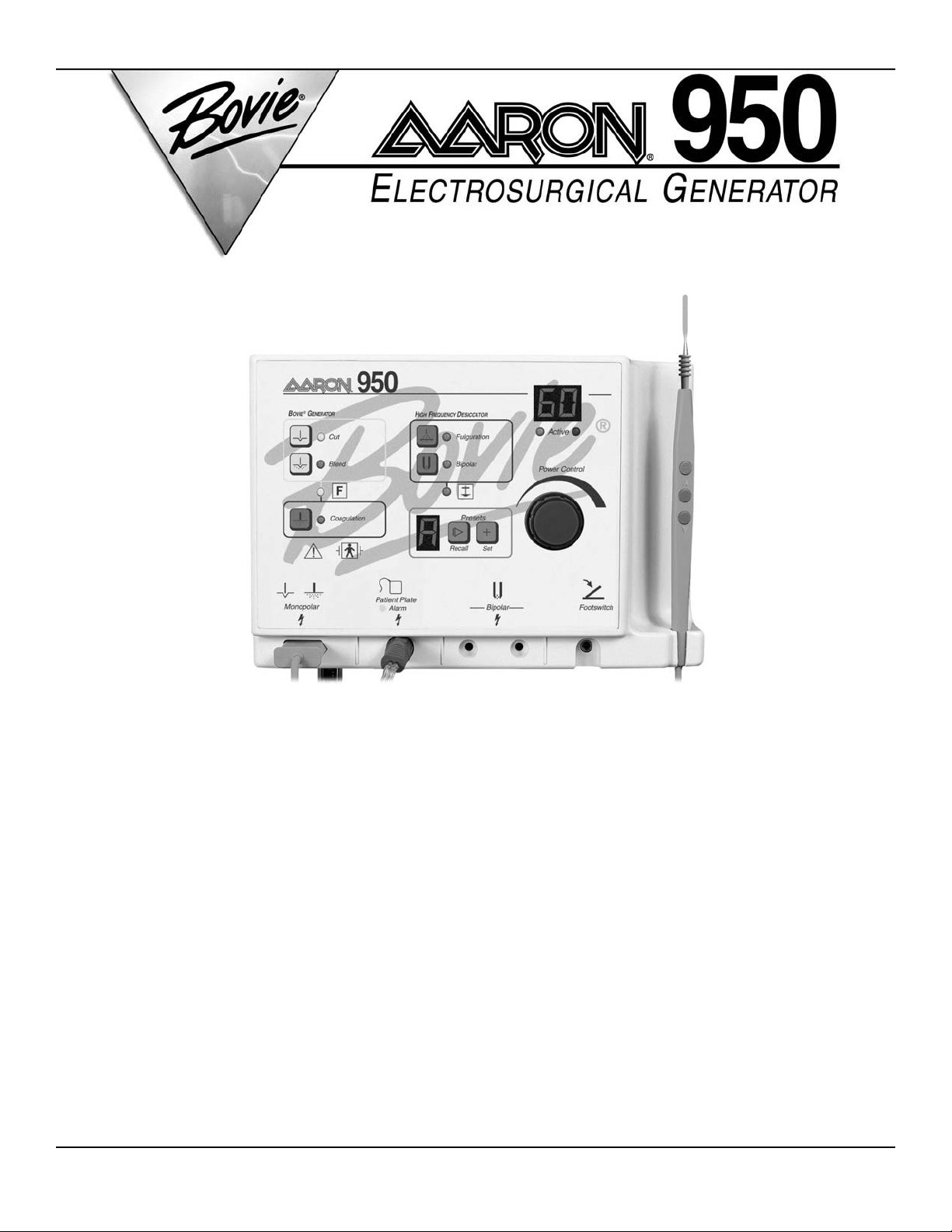
iUser’s Guide • Aaron 950
USER’S GUIDE
Page 2

ii Bovie / Aaron Medical
Page 3

This manual and the equipment it describes are for use only by qualified medical professionals trained in the
WARNING:
Indicates a potentially hazardous situation which, if not avoided, could result in death or serious
injury.
CAUTION:
Indicates a hazardous situation which, if not avoided, may result in minor or moderate injury.
NOTICE:
Indicates an operating tip, a maintenance suggestion, or a hazard that may result in product
damage.
iiiUser’s Guide • Aaron 950
particular technique and surgical procedure to be performed. It is intended as a guide for using the Aaron 950
Electrosurgical Generator only.
Additional technical information is available in the Aaron 950 Service Guide.
Equipment Covered in this Manual
Aaron 950 Electrosurgical Generator:
110 VAC Model No.: A950
220 VAC Model No.: A950-220
For Information Call
Aaron Medical, A Bovie Company • St. Petersburg, FL 33710
U.S. Phone 1-800-537-2790 Fax 1-800-323-1640 • International Phone +1-727-384-2323 Fax +1-727-347-9144
www.aaronmed.com • [email protected]
EU Representative: Peter J. Smith
Medical Products Marketing
18 Yeates Close
Thame OX9 3AR, UK
Made in USA
Printed in USA
©2006 Aaron Medical, A Bovie Company. All rights reserved. Contents of this publication may not be reproduced
without the written permission of Bovie / Aaron Medical.
Aaron Part Number: MC-55-055-001 Rev. 4
CONVENTIONS USED IN THIS GUIDE
Page 4

TABLE OF CONTENTS
Equipment Covered in this Manual ............................................................................iii
For Information Call....................................................................................................iii
Conventions Used in this Guide.........................................................................................iii
Introducing the Aaron 950 Electrosurgical Generator ......................................................1-1
Key Features ...................................................................................................................1-2
Components and Accessories.........................................................................................1-2
Safety ..............................................................................................................................1-2
Controls, Indicators, and Receptacles ................................................................................2-1
Front Panel......................................................................................................................2-2
Symbols on the Front Panel....................................................................................2-3
Cut, Blend, and Coag Controls .......................................................................................2-4
Fulguration, Bipolar, and Preset Controls .......................................................................2-5
Indicators and Receptacles .............................................................................................2-6
Rear and Side Panels .....................................................................................................2-7
Symbols on the Rear Panel ....................................................................................2-7
Symbols on the Side Panel .....................................................................................2-7
Getting Started ......................................................................................................................3-1
Initial Inspection...............................................................................................................3-2
Installing the Unit.............................................................................................................3-2
Using the AARON 950...........................................................................................................4-1
Inspecting the Generator and Accessories .....................................................................4-2
Setup Safety....................................................................................................................4-2
Setting Up........................................................................................................................4-3
Using and Understanding The Aaron 950 Memory Features .........................................4-4
Storing and Recalling Preset Settings.....................................................................4-4
Preparing for Monopolar Surgery....................................................................................4-4
Applying the Patient Return Electrode ....................................................................4-4
Preparing for Bipolar Surgery..........................................................................................4-5
Activation Safety..............................................................................................................4-6
Activating the Unit ...........................................................................................................4-7
Monopolar Activation ...............................................................................................4-7
Bipolar Activation .....................................................................................................4-7
Maintaining the Aaron 950 ...................................................................................................5-1
Cleaning ..........................................................................................................................5-2
Periodic Inspection ..........................................................................................................5-2
Troubleshooting ....................................................................................................................6-1
Repair Policy and Procedures .............................................................................................7-1
Responsibility of the Manufacturer..................................................................................7-2
Returning the Generator for Service ...............................................................................7-2
Step 1 – Obtain a Returned Goods Authorization Number.....................................7-2
Step 2 – Clean the Generator .................................................................................7-2
Step 3 – Ship the Generator ...................................................................................7-3
iv Bovie / Aaron Medical
Page 5

Technical Specifications......................................................................................................A-1
Performance Characteristics...........................................................................................A-2
Input Power .............................................................................................................A-2
Duty Cycle...............................................................................................................A-2
Dimensions and Weight ..........................................................................................A-2
Operating Parameters.............................................................................................A-2
Transport and Storage ............................................................................................A-2
Audio Volume..........................................................................................................A-3
Low Frequency (50–60 Hz) Leakage Current.........................................................A-3
High Frequency (RF) Leakage Current ..................................................................A-3
Standards and IEC Classifications .................................................................................A-4
Class I Equipment (IEC 60601-1) ...........................................................................A-4
Type BF Equipment (IEC 60601-1) / Defibrillator Proof..........................................A-4
Drip Proof (IEC 60601-2-2) .....................................................................................A-4
Electromagnetic Interference ..................................................................................A-4
Electromagnetic Compatibility (IEC 60601-1-2 and IEC 60601-2-2) ......................A-4
Voltage Transients (Emergency Generator Mains Transfer)...................................A-4
Output Characteristics ....................................................................................................A-5
Maximum Output for Bipolar and Monopolar Modes ..............................................A-5
Output Power Curves......................................................................................................A-6
Monopolar Cut Curves ............................................................................................A-6
Monopolar Coag Curves .........................................................................................A-8
Bipolar Curves.......................................................................................................A-10
Accessories...........................................................................................................................B-1
Footswitches ...................................................................................................................B-2
Electrosurgical Pencils....................................................................................................B-2
Dispersive Electrodes .....................................................................................................B-2
Disposable Active Electrodes..........................................................................................B-3
Blade Electrodes .....................................................................................................B-3
Needle Electrodes...................................................................................................B-3
Ball Electrodes ........................................................................................................B-3
LLETZ Electrodes ...........................................................................................................B-4
Ball Electrodes ........................................................................................................B-4
Loop Electrodes ......................................................................................................B-4
Reusable Active Electrodes ............................................................................................B-5
Bipolar Forceps (Reusable) ............................................................................................B-5
Mounting Options............................................................................................................B-6
Warranty ................................................................................................................................C-1
vUser’s Guide • Aaron 950
Page 6

LIST OF FIGURES
Figure 2 – 1 Layout of controls, indicators, and receptacles on the front panel....................2-2
Figure 2 – 2 Controls for the cut, blend, and coag modes ....................................................2-4
Figure 2 – 3 Controls for the fulguration and bipolar modes and presets .............................2-5
Figure 2 – 4 Indicators and receptacles.................................................................................2-6
Figure 2 – 5 Layout of controls and indicators on the rear and side panels .........................2-7
Figure 3 – 1 Mounting kit .......................................................................................................3-2
Figure 4 – 1 Setup procedures ..............................................................................................4-8
Figure A – 1 Output power versus impedance for cut mode .................................................A-6
Figure A – 2 Peak voltage versus power setting for cut mode..............................................A-6
Figure A – 3 Output power versus impedance for blend mode .............................................A-7
Figure A – 4 Peak voltage versus power setting for blend mode..........................................A-7
Figure A – 5 Output power versus impedance for coagulation mode ...................................A-8
Figure A – 6 Peak voltage versus power setting for coagulation mode ................................A-8
Figure A – 7 Output power versus impedance for fulguration mode .....................................A-9
Figure A – 8 Peak voltage versus power setting for fulguration mode .................................A-9
Figure A – 9 Output power versus impedance for bipolar mode .........................................A-10
Figure A – 10 Peak voltage versus power setting for bipolar mode....................................A-10
vi Bovie / Aaron Medical
Page 7

1-1User’s Guide • Aaron 950
INTRODUCING THE AARON 950
ELECTROSURGICAL GENERATOR
This section includes the following information:
●● Key Features
●● Components and Accessories
●● Safety
CAUTIONS
Read all warnings, cautions, and instructions provided with this generator before using.
Read the instructions, warnings, and cautions provided with electrosurgical accessories before
using. Specific instructions are not included in this manual.
Page 8

KEY FEATURES
The Aaron 950 Electrosurgical Generator includes the latest technology. This unit offers unsurpassed performance,
flexibility, reliability, and convenience.
It includes the following features:
•Two levels of coagulation: Pinpoint Coagulation and Fulguration
Pinpoint Coagulation provides precise control of bleeding in localized areas.
Fulguration provides greater control of bleeding in highly vascular tissue over broad surface areas.
•Presets
The unit incorporates six user-defined presets for easy recall of frequently used settings.
• Isolated RF output for Cut, Blend, and Coag modes
This minimizes the potential of alternate site burns.
•Ground Referenced RF output for Fulguration mode
• Self diagnostics
These diagnostics continually monitor the unit to ensure proper performance.
COMPONENTS AND ACCESSORIES
You should receive the following components with your generator:
•Aaron 950 Electrosurgical Generator • A901 Handpiece
• 50 sharp and 50 blunt non-sterile dermal tips • Ten A910 handpiece drapes
•Five disposable electrodes (3 blades, 1 ball, 1 needle) • Hospital-grade power cord
• One reusable grounding cord • Wall mount bracket
•Five disposable grounding pads • User’s Guide
SAFETY
The safe and effective use of electrosurgery depends to a large degree on factors solely under the control of the
operator. There is no substitute for a properly trained and vigilant medical staff. It is important that they read,
understand, and follow the operating instructions supplied with this electrosurgical equipment.
Physicians have used electrosurgical equipment safely in numerous procedures. Before starting any surgical procedure,
the surgeon should be familiar with the medical literature, complications, and hazards of using electrosurgery in that
procedure.
To promote the safe use of the Aaron 950 Electrosurgical Generator, this section presents the warnings and
cautions that appear throughout this user’s guide. So that you can operate this equipment with maximum safety,
it is important that you read, understand, and follow the instructions in these warnings and cautions. It is also
important that you read, understand, and follow the instructions for use in this user’s guide.
1-2 Bovie / Aaron Medical
Page 9

WARNINGS:
Hazardous Electrical Output - This equipment is for use only by trained, licensed physicians.
Danger: Fire / Explosion Hazard - Do not use the Aaron 950 electrosurgical generator in the
presence of flammable anesthetics.
Fire / Explosion Hazard - The following substances will contribute to increased fire and
explosion hazards in the operating room:
• Flammable substances (such as alcohol based skin prepping agents and tinctures)
• Naturally occurring flammable gases which may accumulate in body cavities such as
the bowel
• Oxygen enriched atmospheres
• Oxidizing agents (such as nitrous oxide [N20] atmospheres)
The sparking and heating associated with electrosurgery can provide an ignition source.
Observe fire precautions at all times. When using electrosurgery in the same room with any
of these substances or gases, prevent their accumulation or pooling under surgical drapes,
or within the area where electrosurgery is performed.
Connect the power cord to a properly polarized and grounded power source with the frequency
and voltage characteristics that match those listed on the back of the unit.
Electric Shock Hazard - Connect the generator power cord to a properly grounded receptacle.
Do not use power plug adapters.
Electric Shock Hazard - Always turn off and unplug the generator before cleaning.
Fire Hazard - Do not use extension cords.
Patient Safety - Use the generator only if the self-test has been completed as described.
Otherwise, inaccurate power outputs may result.
Failure of the high frequency electrosurgical equipment could result in an unintended increase
of output power.
The instrument receptacles on this generator are designed to accept only one instrument at
a time. Do not attempt to connect more than one instrument at a time into a given receptacle.
Doing so will cause simultaneous activation of the instruments.
Use the lowest output setting necessary to achieve the desired surgical effect. Use the active
electrode only for the minimum time necessary in order to lessen the possibility of unintended
burn injury. Pediatric applications and/or procedures performed on small anatomic structures
may require reduced power settings. The higher the current flow, and the longer the current is
applied, the greater the possibility of unintended thermal damage to tissue, especially during
use on small structures.
Use electrosurgery with caution in the presence of internal or external pacemakers. Interference
produced by the use of electrosurgical devices can cause devices such as a pacemaker to
enter an asynchronous mode or can block the pacemaker effect entirely. Consult the pacemaker
manufacturer or hospital Cardiology Department for further information when use of electrosurgical
appliances is planned for patients with cardiac pacemakers.
If the patient has an Implantable Cardioverter Defibrillator (ICD), contact the ICD manufacturer
for instructions before performing an electrosurgical procedure. Electrosurgery may cause
multiple activation of ICDs.
Do not use electrosurgical equipment unless properly trained to use it in the specific procedure
being undertaken. Use by physicians without such training has resulted in serious, unintended
patient injury, including bowel perforation and unintended, irreversible tissue necrosis.
For surgical procedures where the high frequency current could flow through parts of the body
having a relatively small cross-sectional area, the use of bipolar techniques may be desirable to
avoid unwanted coagulation.
In some circumstances, potential exists for alternate site burns at points of skin contact
(e.g., between the arm and the side of the body). This occurs when electrosurgical current
seeks a path to the patient return electrode that includes the skin-to-skin contact point.
Current passing through small skin-to-skin contact points is concentrated and may cause
a burn. This is true for grounded, ground referenced, and isolated output generators.
1-3User’s Guide • Aaron 950
Page 10

WARNINGS:
To reduce the potential for alternate site burns, do one or more of the following:
•Avoid skin-to-skin contact points, such as fingers touching leg, when positioning the patient.
• Place 5 to 8 cm (2 to 3 in.) of dry gauze between contact points to ensure that contact does
not occur.
• Position the patient return electrode to provide a direct current route between the surgical
site and the return electrode which avoids skin-to-skin contact areas.
• In addition, place patient return electrodes according to the manufacturer’s instructions.
Potential for alternate site burns increases if the return electrode is compromised.
Do not wrap the accessory cords or patient return electrode cords around metal objects. This
may induce currents that could lead to shocks, fires, or injury to the patient or surgical team.
CAUTIONS:
At no time should you touch the active electrode or bipolar forceps. A burn could result.
Do not stack equipment on top of the generator or place the generator on top of electrical
equipment. These configurations are unstable and/or do not allow adequate cooling.
Provide as much distance as possible between the electrosurgical generator and other electronic
equipment (such as monitors). An activated electrosurgical generator may cause interference
with them.
Nonfunction of the generator may cause interruption of surgery. A backup generator should be
available for use.
Do not turn the activation tone down to an inaudible level. The activation tone alerts the surgical
team when an accessory is active.
When using a smoke evacuator in conjunction with the electrosurgical generator, place the smoke
evacuator a distance from the generator and set the generator volume control at a level that
ensures that the activation tones can be heard.
The use of high frequency current can interfere with the function of other electromagnetic
equipment.
When high frequency surgical equipment and physiological monitoring equipment are used
simultaneously on the same patient, place any monitoring electrodes as far as possible from
the surgical electrodes. Monitoring systems incorporating high frequency current limiting devices
are recommended.
Do not use needles as monitoring electrodes during electrosurgical procedures. Inadvertent
electrosurgical burns may result.
To avoid the possibility of an electrosurgical burn to either the patient or the physicians, do
not allow the patient to come in contact with a grounded metal object during activation.
When activating the unit, do not allow direct skin contact between the patient and the physician.
Remove any loose fitting jewelry from the patient before activation.
Examine all accessories and connections to the electrosurgical generator before use. Ensure that
the accessories function as intended. Improper connection may result in arcs, sparks, accessory
malfunction, or unintended surgical effects.
When not using active accessories, place them in a holster or in a clean, dry, nonconductive,
and highly visible area not in contact with the patient. Inadvertent contact with the patient may
result in burns.
Studies have shown that smoke generated during electrosurgical procedures can be potentially
harmful to patients and the surgical team. These studies recommend adequately ventilating the
smoke by using a surgical smoke evacuator or other means.
1
1. U.S. Department of Health and Human Services. National Institute for Occupational Safety
and Health (NIOSH). Control of Smoke from Laser / Electric Surgical Procedures. HAZARD
CONTROLS, Publication No. 96-128, September, 1996).
1-4 Bovie / Aaron Medical
Page 11

NOTICES:
Do not clean the generator with abrasive cleaning or disinfectant compounds, solvents, or other
materials that could scratch the panels or damage the generator.
1-5User’s Guide • Aaron 950
Page 12

1-6 Bovie / Aaron Medical
Page 13

2-1User’s Guide • Aaron 950
CONTROLS, INDICATORS, AND RECEPTACLES
This section describes:
●● The Front, Rear, and Side Panels
●● Controls, Indicators, and Receptacles
Page 14
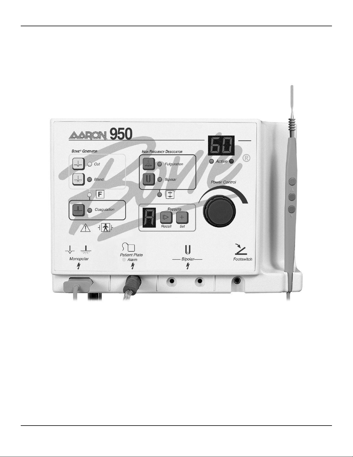
FRONT PANEL
Figure 2 – 1 Layout of controls, indicators, and receptacles on the front panel
2-2 Bovie / Aaron Medical
Page 15
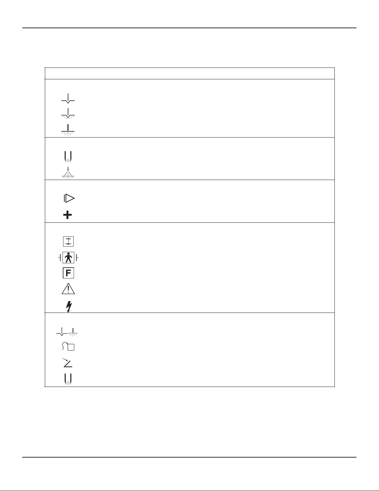
Symbols on the Front Panel
The following table lists descriptions for symbols found on the front panel of the Aaron 950.
2-3User’s Guide • Aaron 950
SYMBOLS DESCRIPTION
Generator Controls
Cut mode
Blend mode
Coagulation mode
High Frequency Desiccator Controls
Bipolar mode
Fulguration mode
Presets
Select next preset
Set new preset
Indicators
RF ground referenced
Defibrillator proof type BF equipment
RF Isolated – patient connections are isolated from earth at high frequency.
Read instructions before use.
Caution - high voltage
Handpiece Connectors
Monopolar handpiece
Patient return electrode
Footswitch
Bipolar forceps
Page 16
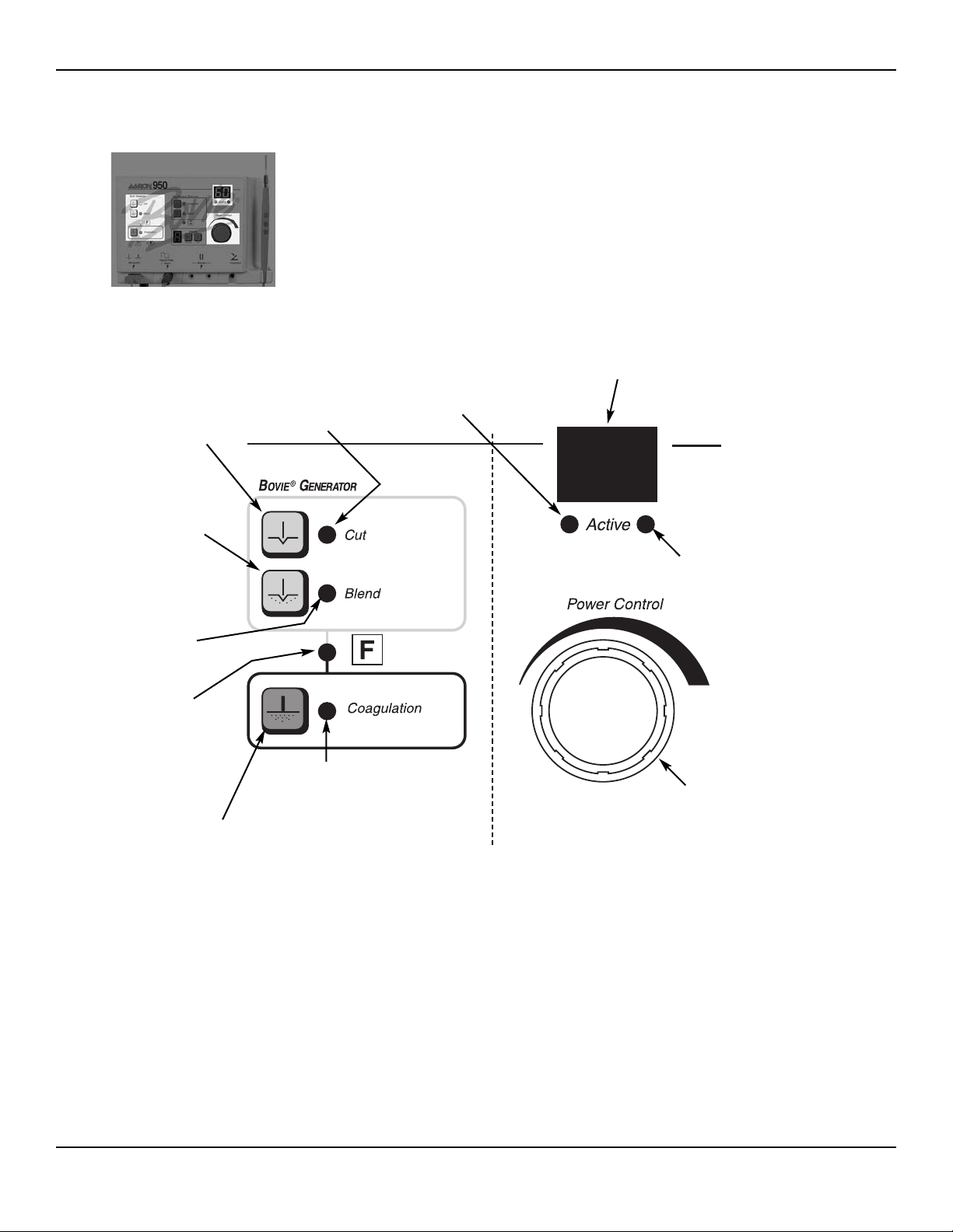
CUT, BLEND, AND COAG CONTROLS
Figure 2 – 2 Controls for the cut, blend, and coag modes
Cut Mode
Selector
When pressed,
selects the pure
cut mode.
Blend Mode
Selector
When pressed,
selects the
blended cut mode.
Blend Indicator
Indicates when
blended cut
mode is selected.
Cut Indicator
Indicates when
pure cut mode
is selected.
Cut, Blend Active Indicator
Indicates that the power
has been activated in the
selected mode.
Power Display (watts)
Indicates the power set for
the selected mode.
Coag, Fulguration, Bipolar
Active Indicator
Indicates that the power
has been activated in the
selected mode.
RF Isolated Indicator
Indicates when the
RF output is isolated
from the ground.
Coag Mode Selector
When pressed, selects
the coagulation mode.
Coag Indicator
Indicates when
coagulation mode
is selected.
Power Output
Control Knob
Turn clockwise to
increase power output,
counterclockwise to
decrease power output.
2-4 Bovie / Aaron Medical
Page 17
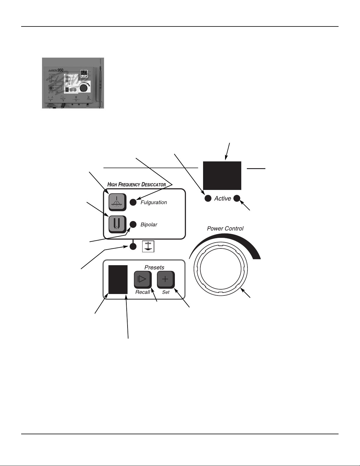
FULGURATION, BIPOLAR, AND PRESET CONTROLS
Figure 2 – 3 Controls for the fulguration and bipolar modes and presets
2-5User’s Guide • Aaron 950
Power Display (watts)
Indicates the power set for
the selected mode.
Cut, Blend Active Indicator
Indicates that the power
has been activated in the
selected mode.
Fulguration Indicator
Indicates when
fulguration mode
is selected.
Fulguration
Mode Selector
When pressed,
selects the
fulguration mode.
Bipolar Mode
Selector
When pressed,
selects the
bipolar mode.
Bipolar Indicator
Indicates when
bipolar mode is
selected.
Presets Display
Indicates which preset is
selected (A-F). “b” and “d” are
displayed in lowercase letters.
RF Ground
Referenced Indicator
Indicates when the RF
output is ground referenced. Only applies to
the fulguration mode.
Presets Recall
Selector
When pressed,
selects the next
preset setting.
No Presets Indicator
Dot blinks to indicate
when no user defined
preset is being used.
Presets Set Button
When depressed for
2 seconds, makes
the current settings
the preset letter
shown in the indicator window.
Coag, Fulguration Bipolar
Active Indicator
Indicates that the power
has been activated in the
selected mode.
Power Output
Control Knob
Turn clockwise to
increase power output,
counterclockwise to
decrease power output.
Page 18
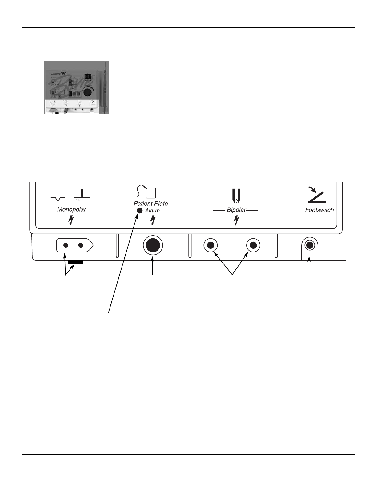
INDICATORS AND RECEPTACLES
Figure 2 – 4 Indicators and receptacles
Monopolar Handpiece
Receptacle
Accepts the Aaron A901
3-button handpiece cord.
Patient Plate Alarm Indicator
Indicates an alarm condition
regarding the patient return
cord or pad.
Patient Plate
Grounding Receptacle
Accepts the Aaron
A1202C reusable
grounding cord.
Bipolar Cord Receptacle
Accepts the Aaron A827EU
bipolar forceps cord.
Footswitch Receptacle
Accepts the Aaron
A1203W footswitch cord.
2-6 Bovie / Aaron Medical
Page 19
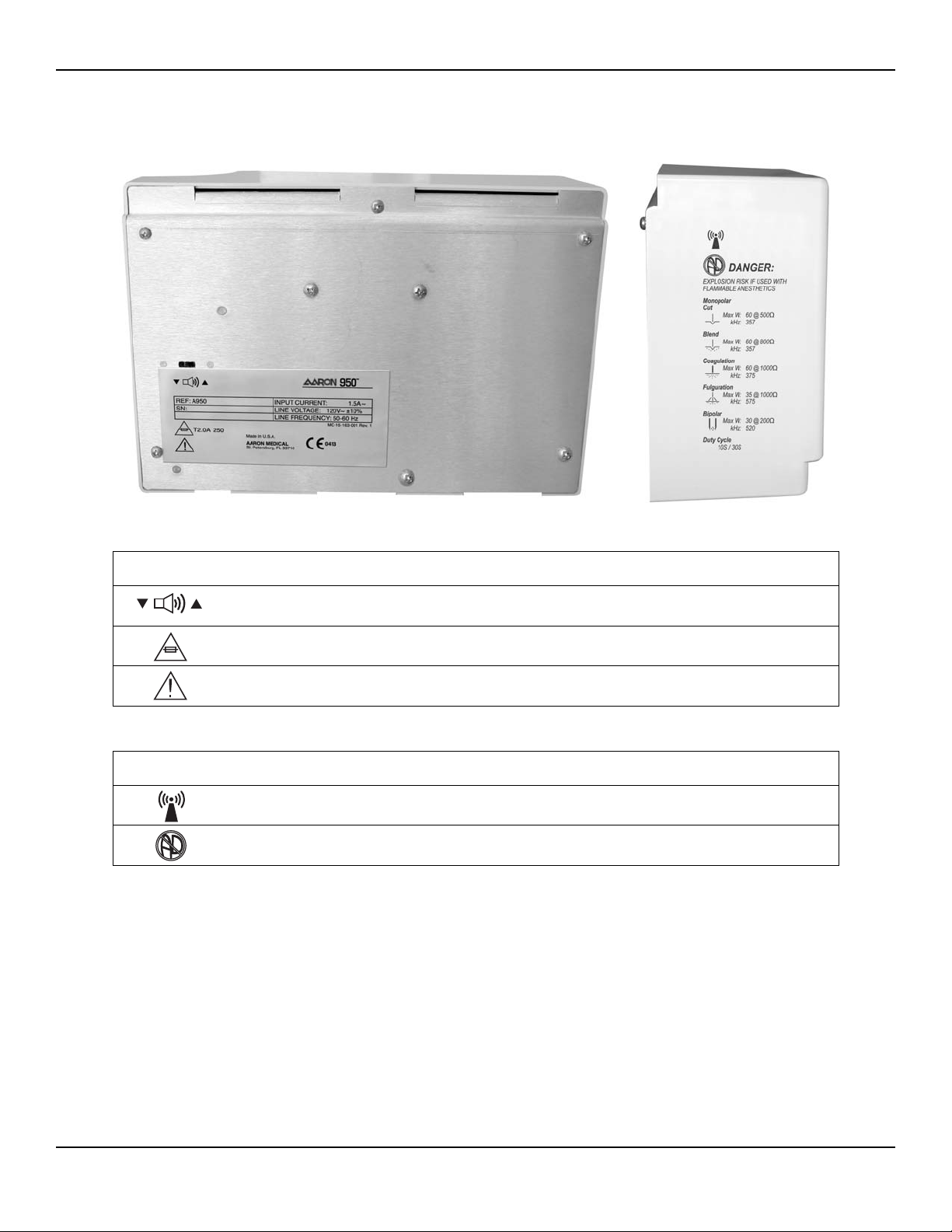
REAR AND SIDE PANELS
Figure 2 – 5 Layout of controls and indicators on the rear and side panels
Symbols on the Rear Panel
Symbols on the Side Panel
2-7User’s Guide • Aaron 950
SYMBOLS DESCRIPTION
Volume control
Fuse enclosed
Read Instructions Before Use
SYMBOLS DESCRIPTION
Non-ionizing Radiation
Danger - Explosion Risk If Used With Flammable Anesthetics.
Page 20

2-8 Bovie / Aaron Medical
Page 21

3-1User’s Guide • Aaron 950
GETTING STARTED
This section includes the following information:
●● Initial Inspection
●● Installing the Unit
Page 22
INITIAL INSPECTION
When you first unpack your Aaron 950 Electrosurgical Generator, inspect it visually:
• Look for any signs of damage.
• Verify that the shipping package contains all items listed on the packing list.
If the unit or any accessories are damaged, notify Aaron Medical’s Customer Service immediately. Do not use any
damaged equipment.
INSTALLING THE UNIT
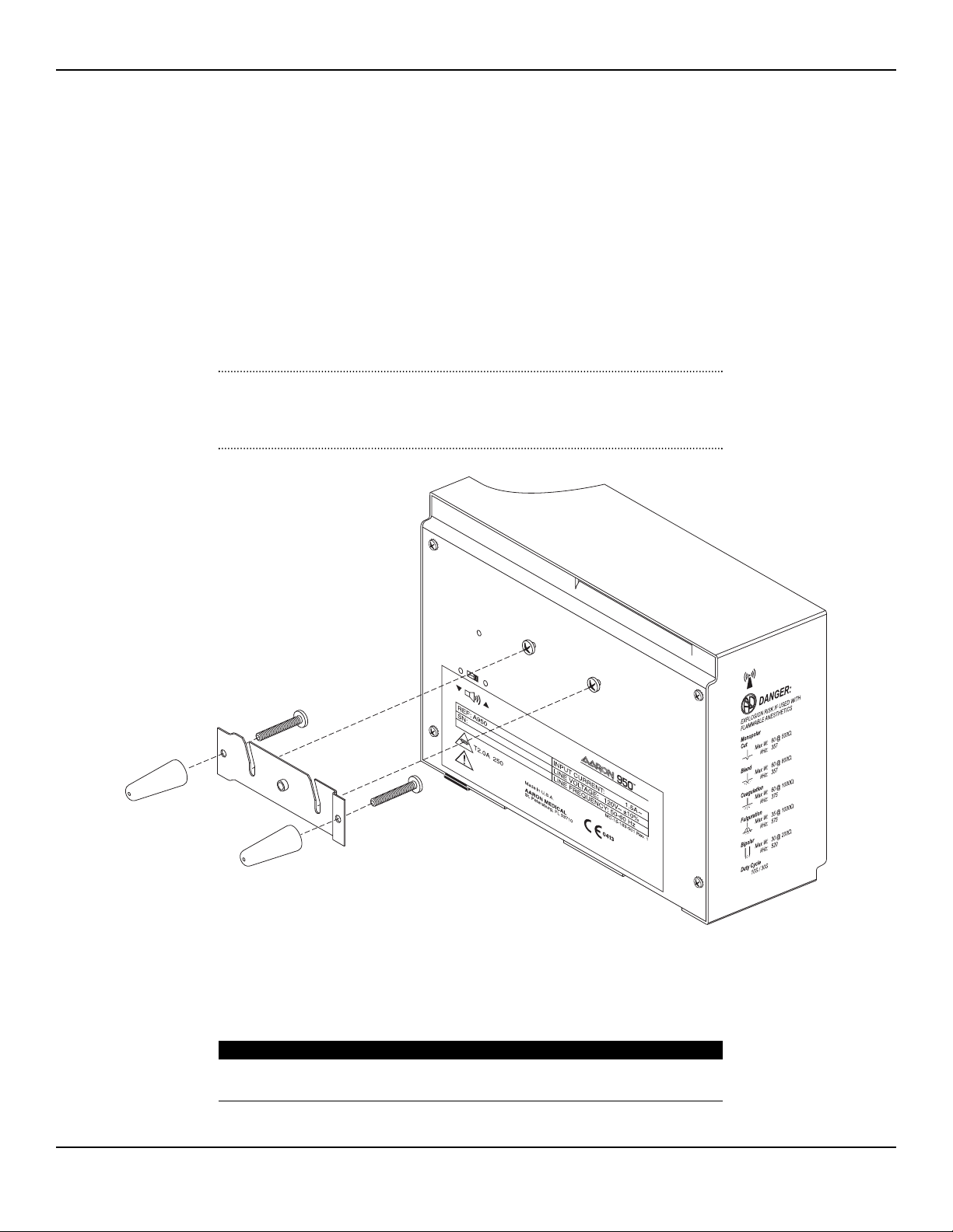
1. Mount the Aaron 950 Electrosurgical Generator on the wall or optional stand using the mounting kit.
(See Figure 3 - 1)
CAUTION:
The unit is not to be utilized in the horizontal position, as liquids may easily spill into the unit.
If mounting on a wall surface, a qualified individual should be consulted to avoid damage to the
wall surface.
Figure 3 – 1 Mounting kit
2. Plug the female end of the supplied power cord into the base of the unit and the male end into a grounded
wall receptacle.
WARNING:
Connect the power cord to a properly polarized and grounded power source with the frequency
and voltage characteristics that match those listed on the back of the unit.
3-2 Bovie / Aaron Medical
Page 23

4-1User’s Guide • Aaron 950
USING THE AARON 950
This section contains the following procedures:
●● Inspecting the Generator and Accessories
●● Setup Safety
●● Setting Up
●● Preparing for Monopolar Surgery
●● Preparing for Bipolar Surgery
●● Activation Safety
●● Activating the Unit
CAUTIONS
Read all warnings, cautions, and instructions provided with this generator before use.
Read the instructions, warnings, and cautions provided with electrosurgical accessories before
use. Specific instructions are not included in this manual.
Page 24

INSPECTING THE GENERATOR AND ACCESSORIES
Before each use of the Aaron 950 Electrosurgical Generator, verify that the unit and all accessories are in good
working order:
•Inspect for damage to the Electrosurgical Generator and all its connections.
•Verify that the appropriate accessories and adapters are present.
•Inspect all cords and connectors for signs of wear, damage, and abrasion.
•Verify that no errors occur when you turn on the unit.
SETUP SAFETY
WARNINGS
Hazardous Electrical Output - This equipment is for use only by trained, licensed physicians.
Electric Shock Hazard - Connect the generator power cord to a properly grounded receptacle.
Do not use power plug adapters.
Connect the power cord to a properly polarized and grounded power source with the frequency
and voltage characteristics that match those listed on the back of the unit.
Fire Hazard - Do not use extension cords.
Patient Safety - Use the generator only if the self-test has been completed as described.
Otherwise, inaccurate power outputs may result.
The instrument receptacles on this generator are designed to accept only one instrument at a
time. Do not attempt to connect more than one instrument at a time into a given receptacle.
Doing so will cause simultaneous activation of the instruments.
Failure of the high frequency electrosurgical equipment could result in an unintended increase of
output power.
Do not use electrosurgical equipment unless properly trained to use it in the specific procedure
being undertaken. Use by physicians without such training has resulted in serious, unintended
patient injury, including bowel perforation and unintended, irreversible tissue necrosis.
For surgical procedures where the high frequency current could flow through parts of the body
having a relatively small cross-sectional area, the use of bipolar techniques may be desirable to
avoid unwanted coagulation.
If the patient has an Implantable Cardioverter Defibrillator (ICD), contact the ICD manufacturer for
instructions before performing an electrosurgical procedure. Electrosurgery may cause multiple
activation of ICDs.
In some circumstances, potential exists for alternate site burns at points of skin contact (e.g.,
between the arm and the side of the body). This occurs when electrosurgical current seeks a path
to the patient return electrode that includes the skin-to-skin contact point. Current passing through
small skin-to-skin contact points is concentrated and may cause a burn. This is true for grounded,
ground referenced, and isolated output generators.
To reduce the potential for alternate site burns, do one or more of the following:
•Avoid skin-to-skin contact points, such as fingers touching leg, when positioning the patient.
• Place 5 to 8 cm (2 to 3 in.) of dry gauze between contact points to ensure that contact does
not occur.
• Position the patient return electrode to provide a direct current route between the surgical
site and the return electrode which avoids skin-to-skin contact areas.
• In addition, place patient return electrodes according to the manufacturer’s instructions.
Potential for alternate site burns increases if the return electrode is compromised.
4-2 Bovie / Aaron Medical
Page 25

CAUTIONS
Do not stack equipment on top of the generator or place the generator on top of electrical
equipment. These configurations are unstable and/or do not allow adequate cooling.
Provide as much distance as possible between the electrosurgical generator and other electronic
equipment (such as monitors). An activated electrosurgical generator may cause interference
with them.
Nonfunction of the generator may cause interruption of surgery. A backup generator should be
available for use.
Do not turn the activation tone down to an inaudible level. The activation tone alerts the surgical
team when an accessory is active.
When using a smoke evacuator in conjunction with the electrosurgical generator, place the smoke
evacuator a distance from the generator and set the generator volume control at a level that
ensures that the activation tones can be heard.
NOTICES
If required by local codes, connect the generator to the hospital equalization connector with an
equipotential cable.
Connect the power cord to a wall outlet having the correct voltage. Otherwise product damage
may result.
SETTING UP
1. If the unit is not already installed refer to Section 3 of this manual for the installation procedure.
2. Turn on the generator by pressing the power switch ON (|) (see figure 4-1, letter G). [Figure 4-1 is located at the end of this
Section]
. Verify the following:
• All visual indicators and displays on the front panel illuminate.
•Activation tones sound to verify that the speaker is working properly.
3. If the self-test is successful, a tone sounds. Verify the following:
• The unit resets to the last activated Preset setting. The Preset display will display a letter from A-F.
Preset letters “b” and “d” will display in lowercase.
• The power display will show the power level for the last used Preset setting.
• The mode for the last activated Preset setting is selected.
If the self-test is not successful, an alarm tone sounds. An error code may appear on the power display, in most
cases, the generator is disabled. Note the error code and refer to Section 6, Troubleshooting.
Once the self-test is successful, connect the accessories and set the generator controls. Refer to Preparing for
Monopolar Surgery or Preparing for Bipolar Surgery later in this section.
4-3User’s Guide • Aaron 950
Page 26

USING AND UNDERSTANDING THE AARON 950 MEMORY FEATURES
The Aaron 950 incorporates six user-defined Presets for easy recall of frequently used settings.
Storing and Recalling Preset Settings
Select the desired preset location (A-F) by pressing the Recall button (see figure 4-1, letter H).
Select the desired mode to be stored by pressing one of the mode membrane switches (see figure 4-1, letter A)
Select the desired power to be stored by utilizing the power output control knob. (see figure 4-1, letter J).
Once all the settings are selected, depress and hold the Presets Set Button (see figure 4-1, letter I) for 2 seconds.
To indicate the settings have been stored, the letter on the Presets indicator will blink.
To r ecall a preset simply press the Presets’ Recall button to toggle through all the presets.
NOTICE:
A small dot blinking in the lower left corner of the Presets indicator indicates that the unit is not
presently set to a user-defined preset.
PREPARING FOR MONOPOLAR SURGERY
Cut, Blend, and Coagulation modes require a patient return electrode.
Applying the Patient Return Electrode
Refer to the manufacturer’s instructions for application site and placement procedures. When using metal plate
patient return electrodes, use a conductive gel specifically designed for electrosurgery. Select a patient return electrode
site with good blood flow. While a properly applied electrode results in minimal tissue heating beneath the electrode,
a good blood flow helps carry heat away from the site.
1. Plug the handpiece into the monopolar output on the lower left of the front of the unit (see figure 4-1, letter B).
The plug is designed to fit in only one direction. Plug the smaller round connector from the handpiece into the
receptacle on the bottom of the unit. The three button handpiece is designed to give the doctor complete fingertip
control of the power settings. The Aaron A901 handpiece is unique: handpieces manufactured by other manufacturers will not function with this unit. Do not use the Aaron A901 handpiece on other brand units.
2. Slide the desired active electrode into the handpiece until it is firmly seated (see figure 4-1, letter M). The handpiece
will accept most standard 3/32” (.24 cm) electrodes.
3. Slide the handpiece from above into the holder on the right side of the unit.
4. Plug the male end of the reusable grounding cord into the Patient Plate receptacle located to the right of the
monopolar output
the snap connector on the end of the reusable grounding cord.
5. An optional footswitch may be used with monopolar procedures. If the footswitch is utilized, plug the footswitch
cable into the footswitch jack (see figure 4-1, letter E). While using a footswitch the output will be delivered via the
handpiece. The activation button on the handpiece will continue to function while a footswitch is connected to
the unit.
(see figure 4-1, letter C). Remove the disposable dispersive electrode from its pouch and attach to
NOTICE:
A return electrode is not required for the fulguration mode. The patient plate alarm is not used for
this mode. Procedures may be performed without the use of a return electrode.
4-4 Bovie / Aaron Medical
Page 27

6. Choose the Monopolar mode of operation by pressing the desired membrane switch on the front panel
(see figure 4-1, letter A). Monopolar modes include Cut, Blend, Coagulation, and Fulguration.
7. Set the output power either by using the dial on the front of the unit (see figure 4-1, letter J) or by the up and down
buttons on the handpiece
(see figure 4-1, letter K). When power level adjustment is being made by the handpiece an
audible tone will sound to indicate that the power level has been changed. Depressing and holding the up or down
buttons will cause the power settings to change more rapidly for quick adjustment of the output power. Power output is displayed in one watt increments for Cut, Blend, and Coagulation mode. The maximum power for each of
these modes is 60 watts. Power is displayed in “.1” watt increments below ten watts and in whole numbers from ten
to 35 watts.
NOTICE:
The output settings cannot be adjusted when the unit is being activated.
8. The unit is now ready to perform surgery. Refer to Activating the Unit later in this section.
PREPARING FOR BIPOLAR SURGERY
1. Insert the two connectors from the bipolar cable into the bipolar cord receptacles (see figure 4-1, letter D).
2. Connect the desired forcep to the operating end of the bipolar cord.
3. Plug the footswitch cable into the footswitch jack
(see figure 4-1, letter E). A footswitch is required to activate the
Bipolar mode.
NOTICE:
Dispersive electrodes are not utilized during bipolar procedures.
4. Select the Bipolar mode by pressing the membrane switch on the front of the unit (see figure 4-1, letter A).
5. Set the output power either by using the dial on the front of the unit (see figure 4-1, letter J) or by the up and down
buttons on the handpiece (see figure 4-1, letter K). When power level adjustment is being made by the handpiece an
audible tone will sound to indicate that the power level has been changed. Depressing and holding the up or down
buttons will cause the power settings to change more rapidly for quick adjustment of the output power. Power is
displayed in “.1” watt increments below ten watts and in whole numbers from ten to 30 watts.
NOTICE:
The output settings cannot be adjusted when the unit is being activated.
6. The unit is now ready to perform surgery. Refer to Activating the Unit later in this section.
4-5User’s Guide • Aaron 950
Page 28

ACTIVATION SAFETY
WARNINGS
Do not wrap the accessory cords or patient return electrode cords around metal objects.
This may induce currents that could lead to shocks, fires, or injury to the patient or surgical team.
Danger: Fire / Explosion Hazard - Do not use the Aaron 950 Electrosurgical Generator in the
presence of flammable anesthetics.
Fire / Explosion Hazard - The following substances will contribute to increased fire and explosion
hazards in the operating room:
• Flammable substances (such as alcohol based skin prepping agents and tinctures)
• Naturally occurring flammable gases that may accumulate in body cavities such as the bowel
• Oxygen enriched atmospheres
• Oxidizing agents (such as nitrous oxide [N2O] atmospheres)
The sparking and heating associated with electrosurgery can provide an ignition source. Observe
fire precautions at all times. When using electrosurgery in the same room with any of these
substances or gases, prevent their accumulation or pooling under surgical drapes, or within the
area where electrosurgery is performed.
Use the lowest output setting necessary to achieve the desired surgical effect. Use the active
electrode only for the minimum time necessary in order to lessen the possibility of unintended
burn injury. Pediatric applications and/or procedures performed on small anatomic structures may
require reduced power settings. The higher the current flow, and the longer the current is applied,
the greater the possibility of unintended thermal damage to tissue, especially during use on small
structures.
Use electrosurgery with caution in the presence of internal or external pacemakers. Interference
produced by the use of electrosurgical devices can cause devices such as a pacemaker to enter
an asynchronous mode or can block the pacemaker effect entirely. Consult the pacemaker
manufacturer or hospital Cardiology Department for further information when use of
electrosurgical appliances is planned for patients with cardiac pacemakers.
CAUTIONS
The use of high frequency current can interfere with the function of other electromagnetic
equipment.
When high frequency surgical equipment and physiological monitoring equipment are used
simultaneously on the same patient, place any monitoring electrodes as far as possible from
the surgical electrodes. Monitoring systems incorporating high frequency current limiting devices
are recommended.
Do not use needles as monitoring electrodes during electrosurgical procedures. Inadvertent
electrosurgical burns may result.
To avoid the possibility of an electrosurgical burn to either the patient or the physicians, do not
allow the patient to come in contact with a grounded metal object during activation. When
activating the unit, do not allow direct skin contact between the patient and the physician.
Remove any loose fitting jewelry from the patient before activation.
Examine all accessories and connections to the electrosurgical generator before use. Ensure that
the accessories function as intended. Improper connection may result in arcs, sparks, accessory
malfunction, or unintended surgical effects.
When not using active accessories, place them in a holster or in a clean, dry, nonconductive,
and highly visible area not in contact with the patient. Inadvertent contact with the patient
may result in burns.
Studies have shown that smoke generated during electrosurgical procedures can be potentially
harmful to patients and the surgical team. These studies recommend adequately ventilating the
smoke by using a surgical smoke evacuator or other means.
1. U.S. Department of Health and Human Services. National Institute for Occupational Safety
and Health (NIOSH). Control of Smoke from Laser / Electric Surgical Procedures. HAZARD
CONTROLS, Publication No. 96-128, September, 1996.)
1
4-6 Bovie / Aaron Medical
Page 29

ACTIVATING THE UNIT
Monopolar Activation
1. If the unit is not already set up, follow the set up procedure to prepare the unit for operation.
2. Remove the handpiece from the holder. Place the handpiece in the desired position.
3. To activate the unit, depress the activation button on the handpiece (see figure 4-1, letter L) or depress the pedal on
the footswitch. While the unit is activated, the appropriate audible tone is sounded and one of the activation LEDs
will illuminate (see figure 4-1, letter N).
4. When the procedure is completed, turn the unit off.
5. Return the handpiece to the holder on the right side of the unit and remove the electrode. The electrode should
be disposed of after each procedure. If contamination has occurred to the handpiece, the handpiece should be
sterilized.
NOTICE:
When sterilizing the handpiece follow the manufacturer’s sterilization instructions that accompany
the handpiece.
Bipolar Activation
1. If the unit is not already set up, follow the set up procedure to prepare the unit for operation.
2. Place the forceps in the desired position.
3. To activate the unit depress the footswitch pedal. While the unit is activated, an audible tone is sounded and the
blue activation LED will illuminate (see figure 4-1, letter N).
4. When the procedure is completed, turn the unit off.
5. Remove the forceps from the bipolar cord and sterilize.
NOTICE:
When sterilizing the forceps follow the manufactures sterilization instructions that accompany the
forceps.
4-7User’s Guide • Aaron 950
Page 30
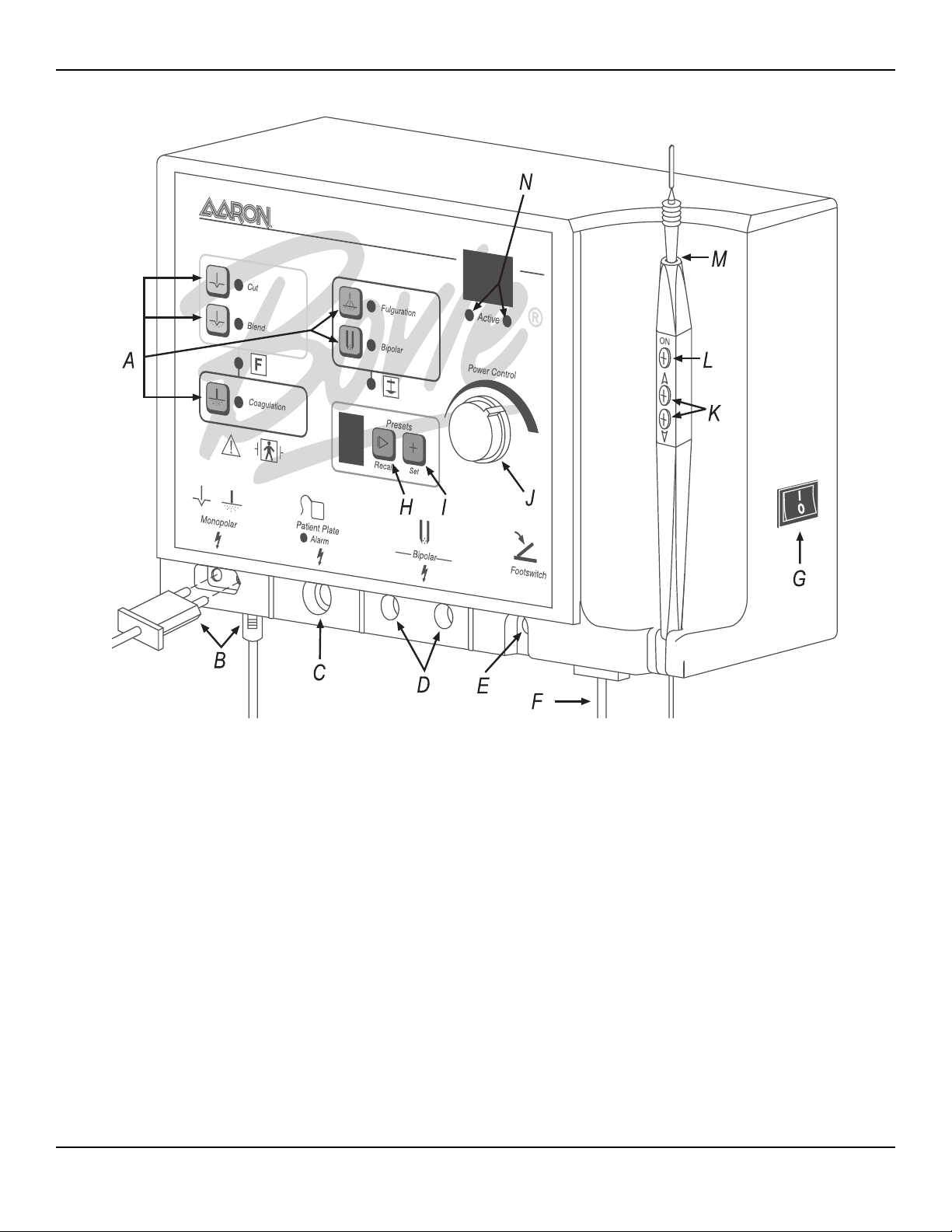
Figure 4 – 1 Setup procedures
950
B
OVIE
®
G
ENERATOR
H
IGH
F
REQUENCY
D
ESICCATOR
4-8 Bovie / Aaron Medical
Page 31

5-1User’s Guide • Aaron 950
MAINTAINING THE AARON 950
This section covers the following topics:
●● Cleaning
●● Per iodic Inspection
Page 32

Aaron Medical recommends that you complete periodic inspection and performance testing. Perform inspections and
performance testing every six months. A qualified biomedical technician should conduct this testing to ensure that
the unit is operating effectively and safely.
CLEANING
After each use, clean the unit.
WARNING:
Electric Shock Hazard - Always turn off and unplug the generator before cleaning.
NOTICE:
Do not clean the generator with abrasive cleaning or disinfectant compounds, solvents, or other
materials that could scratch the panels or damage the generator.
1. Tu rn off the generator, and unplug the power cord from the wall outlet.
2. Thoroughly wipe all surfaces of the generator and power cord with a mild cleaning solution or disinfectant and
a damp cloth. Follow the procedures approved by your institution or use a validated infection control procedure.
Do not allow fluids to enter the chassis. Do not sterilize the generator.
PERIODIC INSPECTION
Every six months, visually inspect the Aaron 950 Electrosurgical Generator for signs of wear or damage.
In particular, look for any of the following problems:
• Damage to the power cord
• Damage to the power cable receptacle
•Obvious damage to the unit
• Damage to any receptacle
•Accumulation of lint or debris in or around the unit
5-2 Bovie / Aaron Medical
Page 33

6-1User’s Guide • Aaron 950
TROUBLESHOOTING
This section includes error code descriptions and actions to take to resolve them.
Page 34

The Aaron 950 Electrosurgical Generator includes automatic self-diagnostics. If the diagnostics detect an error, the
system displays an error code, sounds an audible tone, and deactivates the unit output power.
Most error codes result from faults in accessories attached to the unit. The following table lists the error codes,
describes the error, and recommends actions to take to resolve the error.
Error Code Description Recommended Action
1. Turn off, then turn on the generator. Do not press buttons or activate
accessory devices during the self-test.
2. If the error code reappears, disconnect all accessories.
F1
E2
Handswitch or monopolar
footswitch pedal may be stuck
Line voltage error
(Line voltage is too high)
Turn off, then turn on the generator again.
3. If the problem persists, replace the handpiece or footswitch
and repeat the restart.
4. If the error code reappears, record the number and call
Aaron customer service.
1. Turn the unit off.
2. Verify that the unit is connected to the correct line voltage
3. If the error code reappears, record the number and contact
Aaron customer service.
1. Turn the unit off.
E5
If the unit displays any other error code, it requires service.
Internal temperature of the unit
exceeded limit
2. Allow the unit to cool for 20 minutes.
3. Turn the unit on.
4. If the error code reappears, record the number and contact
Aaron customer service.
6-2 Bovie / Aaron Medical
Page 35

7-1User’s Guide • Aaron 950
REPAIR POLICY AND PROCEDURES
Refer to this section for information on:
●● The Manufacturer’s Responsibility
●● Returning the Generator for Service
Page 36

RESPONSIBILITY OF THE MANUFACTURER
Aaron Medical is responsible for the safety, reliability, and performance of the generator only under the following
circumstances:
• The user has followed the installation and setup procedures in this user’s guide.
•Persons authorized by Aaron Medical performed assembly operation, readjustments, modifications, or repairs.
• The electrical installation of the relevant room complies with local codes and regulatory requirements, such as
IEC and BSI.
•Equipment use is in accordance with the Aaron Medical instructions for use.
For warranty information, refer to Appendix C – Warranty.
RETURNING THE GENERATOR FOR SERVICE
Before you return the generator, call your Aaron Medical representative for assistance. If instructed to send the
generator to Aaron Medical, first obtain a Returned Goods Authorization Number. Then clean the Generator
and ship it to Aaron Medical for service.
Step 1 – Obtain a Returned Goods Authorization Number
Call the Aaron Medical Customer Service Center to obtain a Returned Goods Authorization Number.
Have the following information ready when you call:
• Hospital / clinic name / customer number
•Telephone number
• Department / address, city, state, and zip code
•Model number
• Serial number
• Description of the problem
•Type of repair to be done
Step 2 – Clean the Generator
WARNING:
Electric Shock Hazard - Always turn off and unplug the generator before cleaning.
NOTICE:
Do not clean the generator with abrasive cleaning or disinfectant compounds, solvents, or other
materials that could scratch the panels or damage the generator.
A. Turn off the generator, and unplug the power cord from the wall outlet.
B. Thoroughly wipe all surfaces of the generator and power cord with a mild cleaning solution or disinfectant and
a damp cloth. Follow the procedures approved by your institution or use a validated infection control procedure.
Do not allow fluids to enter the chassis. You cannot sterilize the generator.
7-2 Bovie / Aaron Medical
Page 37

Step 3 – Ship the Generator
A. Attach a tag to the generator that includes the Returned Goods Authorization Number and the information
(hospital, phone number, etc.) listed in Step 1 – Obtain a Returned Goods Authorization Number.
B. Be sure the generator is completely dry before you pack it for shipment. Package it in its original shipping
container, if available.
C. Ship the generator, prepaid, to the address given to you by the Aaron Medical Service Center.
7-3User’s Guide • Aaron 950
Page 38

7-4 Bovie / Aaron Medical
Page 39

A-1User’s Guide • Aaron 950
TECHNICAL SPECIFICATIONS
All specifications are nominal and subject to change without notice. A specification referred to as “typical”
is within ± 20% of a stated value at room temperature (25° C / 77° F) and a nominal input power voltage.
Page 40

PERFORMANCE CHARACTERISTICS
Input Power
120 VAC ± 10% 220 VAC ± 10%
Mains line frequency: 50 – 60 Hz Mains line frequency: 50 – 60 Hz
Power consumption: 240 VA Power consumption: 240 VA
Fuses (two): 2.0 A (Slow Blow) Fuses (two): 1.0 A (Slow Blow)
Duty Cycle
Under maximum power settings and rated load conditions (Pure Cut, 60 watt @ 500 Ω load), the generator is
suitable for activation times of 10 seconds on, 30 seconds off for one hour.
Dimensions and Weight
Width
Height
26 cm (10.25 in.)
17.8 cm (7.0 in.)
Operating Parameters
Ambient temperature range
Relative humidity
Atmospheric pressure
Warm-up time
Transport and Storage
Ambient temperature range
Relative humidity
Atmospheric pressure
Depth
Weight
10° to 40° C (50° to 104° F)
30% to 75%, non-condensing
700 hPa to 1060 hPa
If transported or stored at temperatures outside the operating temperature range,
allow one hour for the generator to reach room temperature before use.
-34˚ to 65˚ C (-29˚ to 149˚ F)
0% to 75%, non-condensing
500 hPa to 1060 hPa
11.4 cm (4.5 in.)
< 15.4 kg (< 7 lbs)
A-2 Bovie / Aaron Medical
Page 41

Audio Volume
The audio levels stated below are for activation tones (bipolar, cut, and coag) and alarm tones (return electrode and
system alarms) at a distance of one meter. Alarm tones meet the requirements for IEC 60601-2-2.
Activation Tone
Alarm Tone
Low Frequency (50–60 Hz) Leakage Current
High Frequency (RF) Leakage Current
A-3User’s Guide • Aaron 950
Volume (adjustable)
45 to 65 dB
Frequency
Cut: 1 kHz
Blend: 1 kHz
Coagulation: 2 kHz
Fulguration: 2 kHz
Bipolar: 2 kHz
Duration
Continuous while the generator is activated
Volume (not adjustable)
70 dB ± 5 dB
Frequency
2 kHz 1⁄
2 seconds / 1 kHz
1
⁄
2 seconds
Duration
2 s
Enclosure source current, ground open
< 500 µA
Source current, patient leads, all outputs
Normal polarity, intact ground: < 50 µA
Normal polarity, ground open: < 50 µA
Reverse polarity, ground open: < 50 µA
Sink current at high line, all inputs
< 50 µA
Bipolar RF leakage current
< 39 mA
rms
Monopolar RF leakage current (additional tolerance)
< 150 mA
rms
Page 42

STANDARDS AND IEC CLASSIFICATIONS
Class I Equipment (IEC 60601-1)
Accessible conductive parts cannot become live in the event of a basic insulation failure because of the way in which
they are connected to the protective earth conductor.
Type BF Equipment (IEC 60601-1) / Defibrillator Proof
The Aaron 950 Electrosurgical Generator provides a high degree of protection against electric shock,
particularly regarding allowable leakage currents. It is type BF equipment. Patient connections are isolated
from earth and resist the effects of defibrillator discharge.
Drip Proof (IEC 60601-2-2)
The generator enclosure is constructed so that liquid spillage in normal use does not wet electrical insulation or other
components which, when wet, are likely to affect adversely the safety of the generator.
Electromagnetic Interference
When other equipment is placed on or beneath an activated Aaron Medical electrosurgical generator, the Aaron 950
Electrosurgical Generator operates without interference. The generator minimizes electromagnetic interference to
video equipment used in the operating room.
Electromagnetic Compatibility (IEC 60601-1-2 and IEC 60601-2-2)
The Aaron 950 Electrosurgical Generator complies with the appropriate IEC 60601-1-2 and IEC 60601-2-2
specifications regarding electromagnetic compatibility.
Vo ltage Transients (Emergency Generator Mains Transfer)
The Aaron 950 Electrosurgical Generator operates in a safe manner when the transfer is made between line AC and
an emergency generator voltage source.
A-4 Bovie / Aaron Medical
Page 43

OUTPUT CHARACTERISTICS
Maximum Output for Bipolar and Monopolar Modes
Power readouts agree with actual power into rated load to within 20% or 5 watts, whichever is greater.
A-5User’s Guide • Aaron 950
Mode Output Power Output Frequency Repetition Rate Vp-p max
Cut 60 W @ 500 Ω 357 kHz ± 50 kHz N / A 1.5 KV
Blend 60 W @ 800 Ω 357 kHz ± 50 kHz 30 kHz ± 5 kHz 2.0 KV
Coagulation 60 W @ 1000 Ω 375 kHz ± 50 kHz 60 kHz ± 5 kHz 3.8 KV
Fulguration 35 W @ 1000 Ω 575 kHz ± 50 kHz 30 kHz ± 5 kHz 6.5 KV
Bipolar 30 W @ 200 Ω 520 kHz ± 50 kHz 19 kHz ± 5 kHz 2.0 KV
Page 44
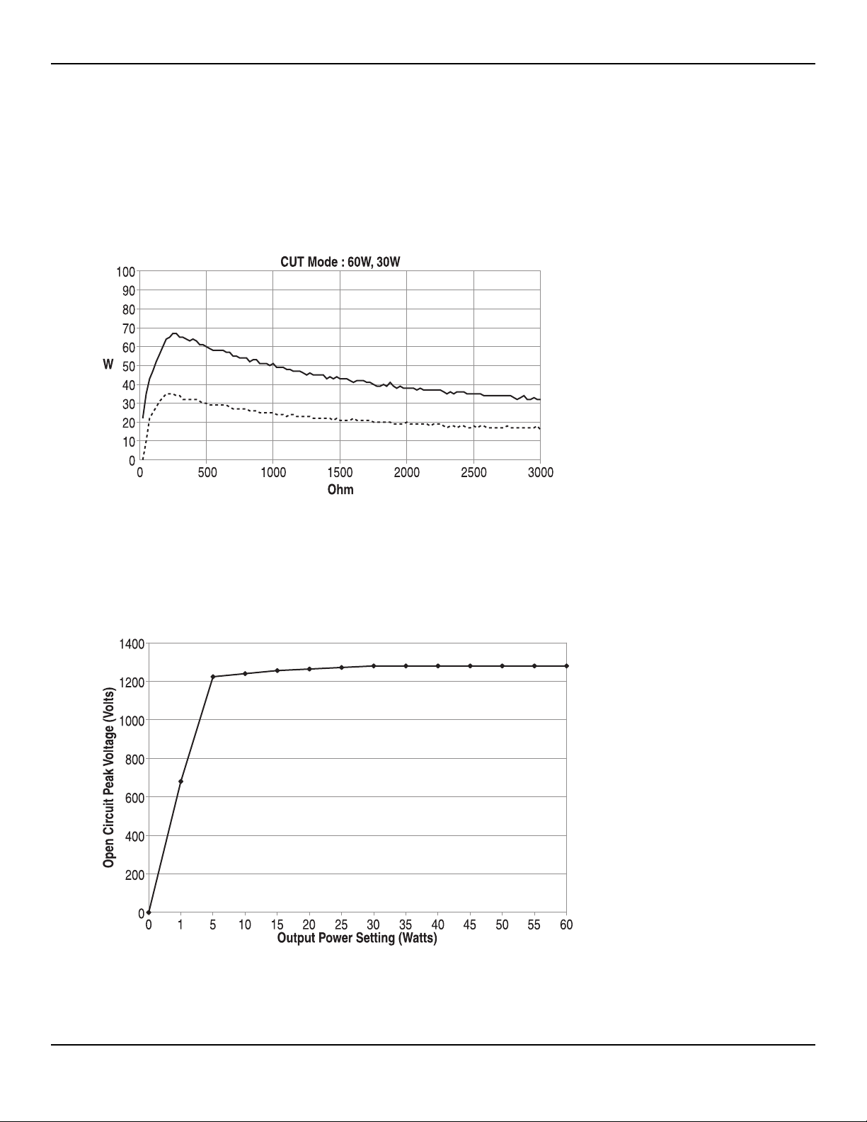
OUTPUT POWER CURVES
The curves that follow depict the changes for each mode at specific power settings.
Monopolar Cut Curves
These measurements were taken using short (< 0.5 meter) leads. For each output power vs. impedance curve, the
upper curve represents readings taken at full power; the lower curve, readings taken at half power.
Figure A – 1 Output power versus impedance for cut mode
Figure A – 2 Peak voltage versus power setting for cut mode
A-6 Bovie / Aaron Medical
Page 45
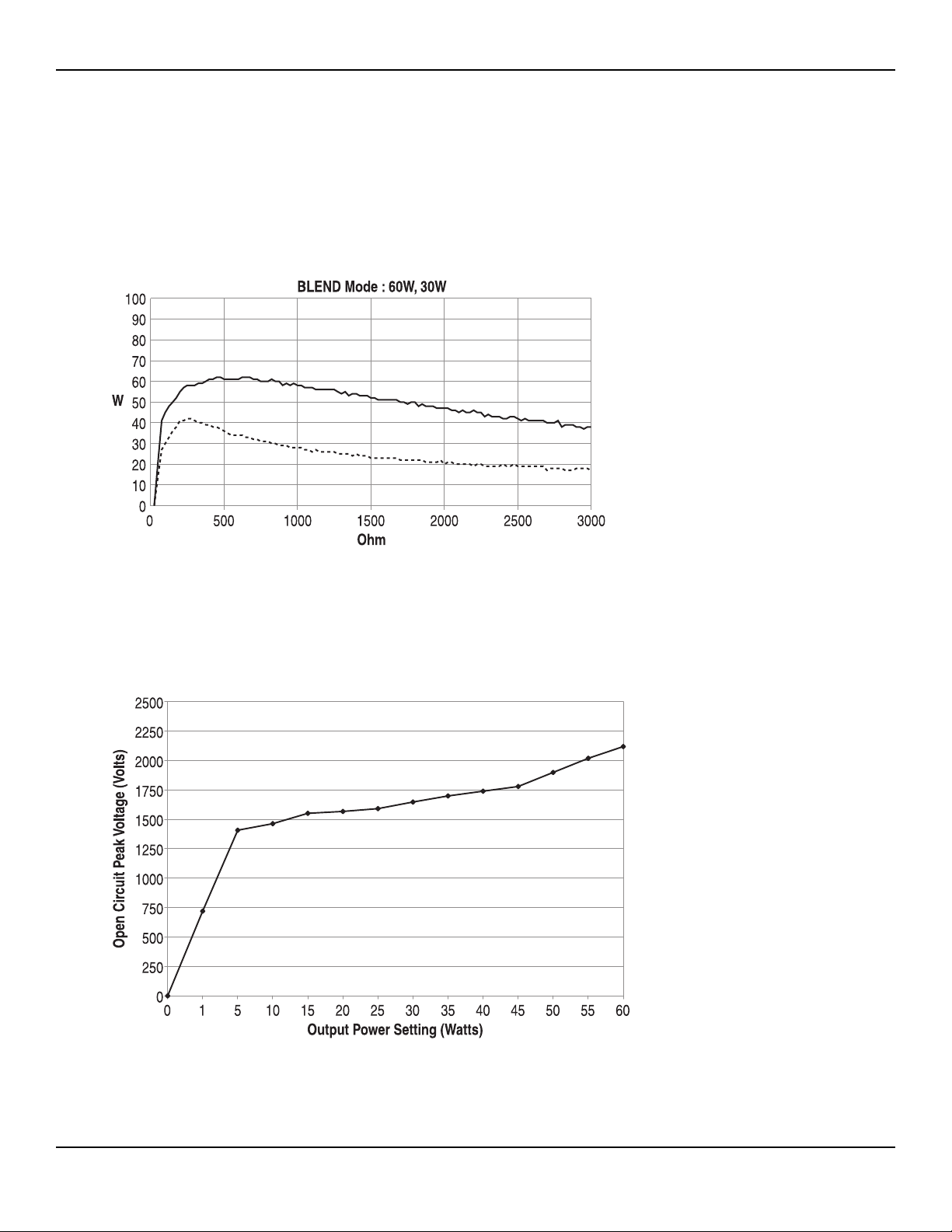
Figure A – 3 Output power versus impedance for blend mode
Figure A – 4 Peak voltage versus power setting for blend mode
A-7User’s Guide • Aaron 950
Page 46
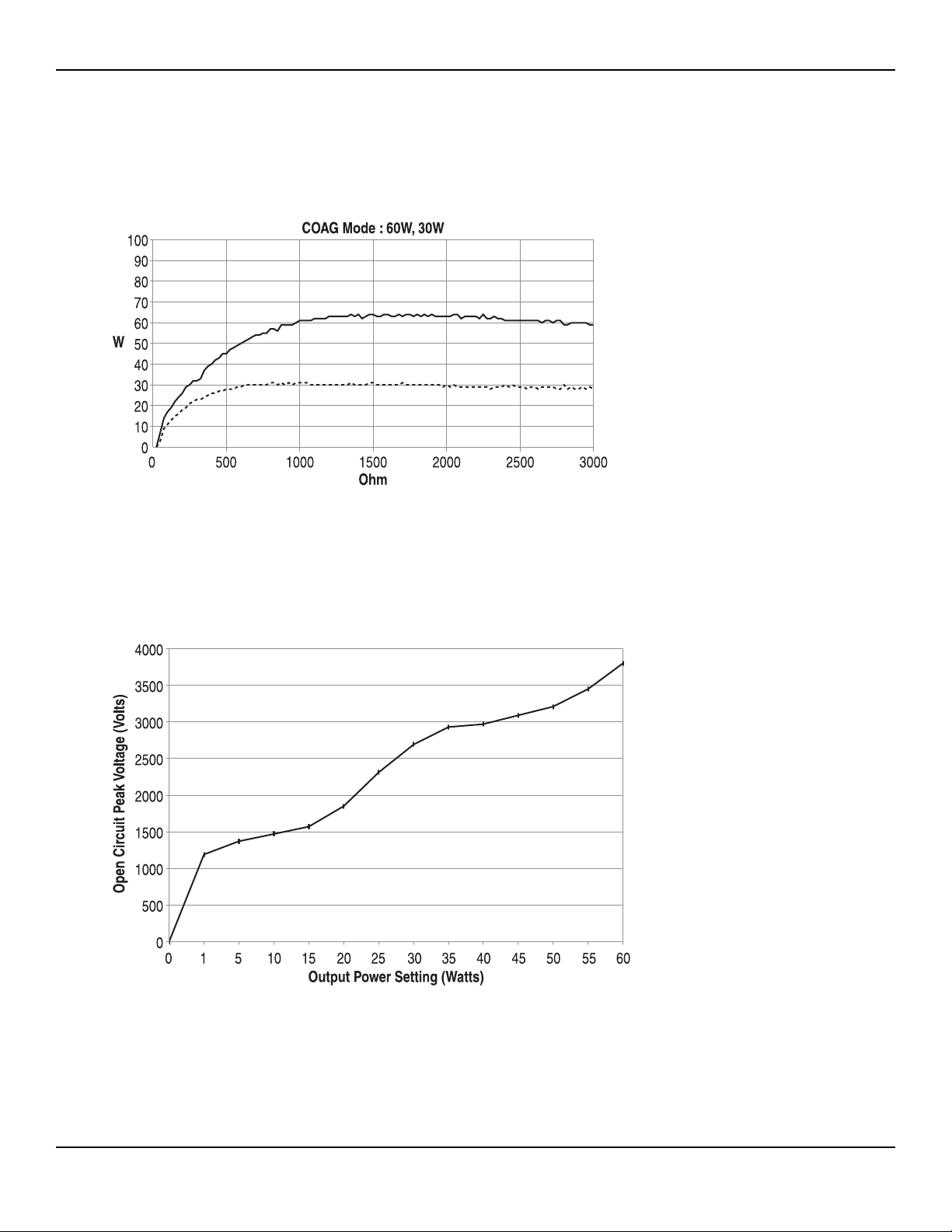
Monopolar Coag Curves
These measurements were taken using short (< 0.5 meter) leads.
Figure A – 5 Output power versus impedance for coagulation mode
Figure A – 6 Peak voltage versus power setting for coagulation mode
A-8 Bovie / Aaron Medical
Page 47
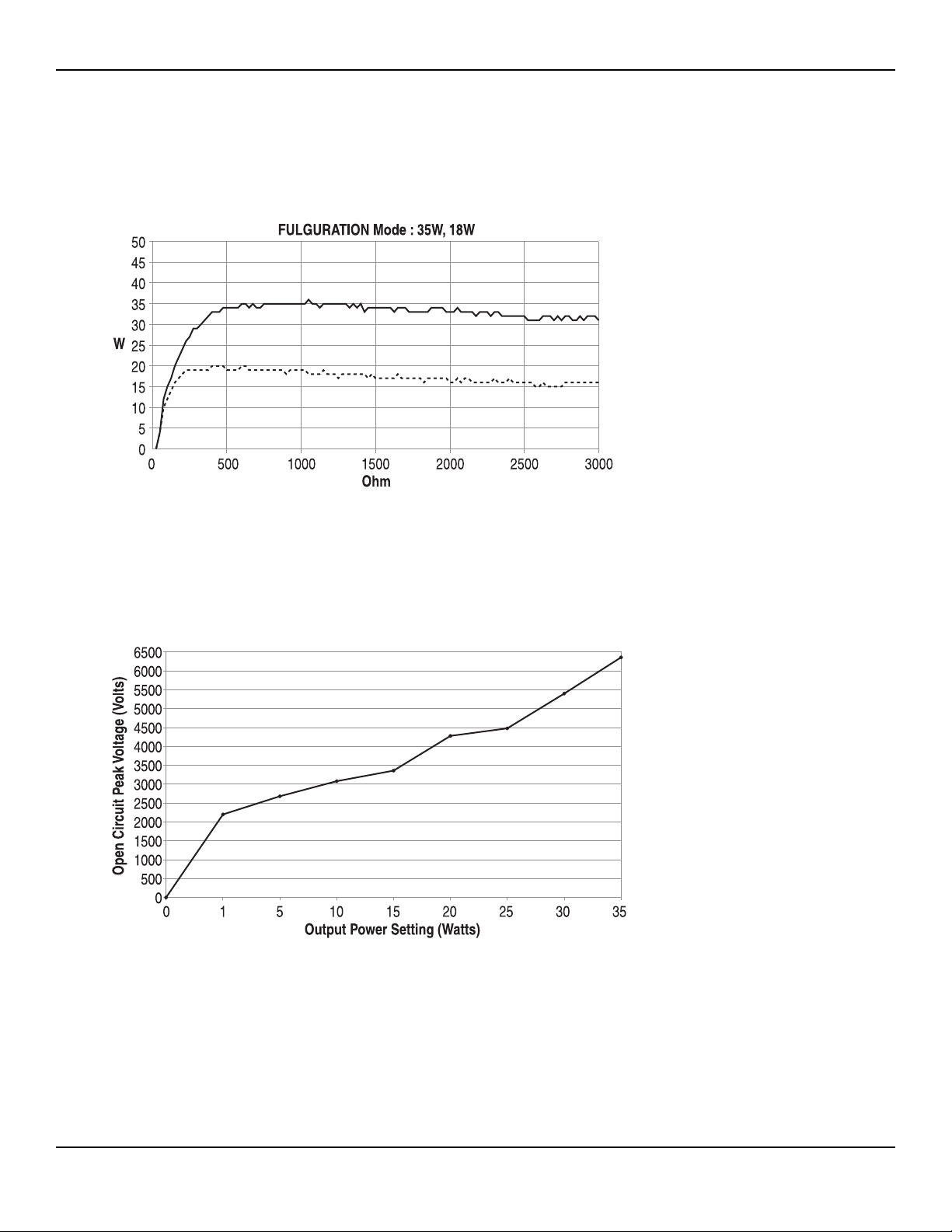
Figure A – 7 Output power versus impedance for fulguration mode
Figure A – 8 Peak voltage versus power setting for fulguration mode
A-9User’s Guide • Aaron 950
Page 48
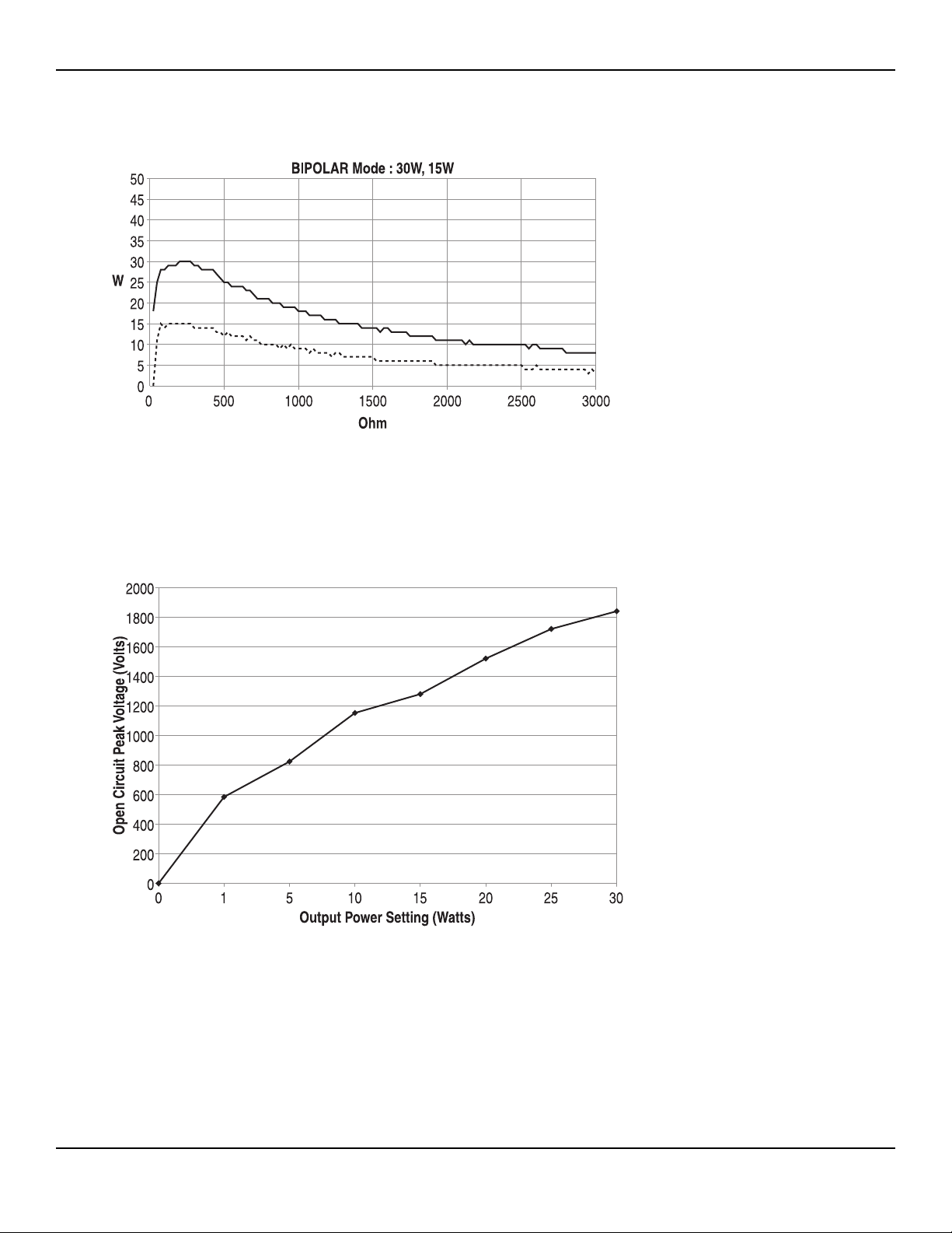
Bipolar Curves
Figure A – 9 Output power versus impedance for bipolar mode
Figure A – 10 Peak voltage versus power setting for bipolar mode
A-10 Bovie / Aaron Medical
Page 49

B-1User’s Guide • Aaron 950
ACCESSORIES
The accessories listed in this section are recommended for use with the Aaron 950 Electrosurgical Generator. Ensure
all accessories are rated for at least the maximum peak output voltage of the generator.
Page 50
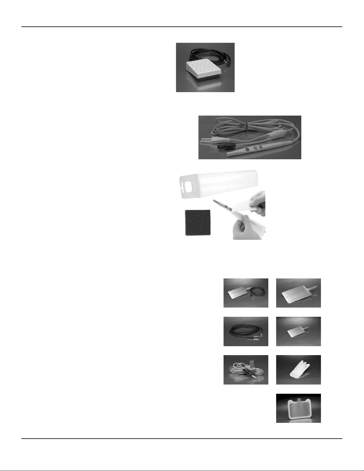
FOOTSWITCHES
A1203W Aaron 950 Footswitch, Each
ELECTROSURGICAL PENCILS
The Standard Aaron 3-button pencil features up down controls
and activation button as well as being able to be activated by the
footswitch.
A901 3-button Handpiece, Each
ESPH Holster for ES Pencil (sterile), Box/40
A910 Disposable Handpiece Sheath, Box/100
ESSP Scratch Pads (sterile), Box/40
DISPERSIVE ELECTRODES
Aaron disposable dispersive electrodes with super adhesive gel are designed
for single use with safety and quality built in. Where reusability is needed a
reusable electrode and cable are available.
A1204Reusable Metal Plate and Cord, Each
A1204P Reusable Replacement Plate for A1204, Each
A1204C Reusable Replacement Cord for A1204, Each
A1207Reusable Metal Pediatric Plate, Each
A1202C Reusable Connecting Cord for A1202/ESRS, Each
A1202Disposable Solid Adult Return Electrode w/o Cable, Box/5
ESRS Disposable Solid Adult Return Electrode w/o Cable, Box/50
B-2 Bovie / Aaron Medical
A1203W
A901
ESRS
A1202A1202C
A1207A1204C
A1204PA1204
ESPH
A910
ESSP
Page 51
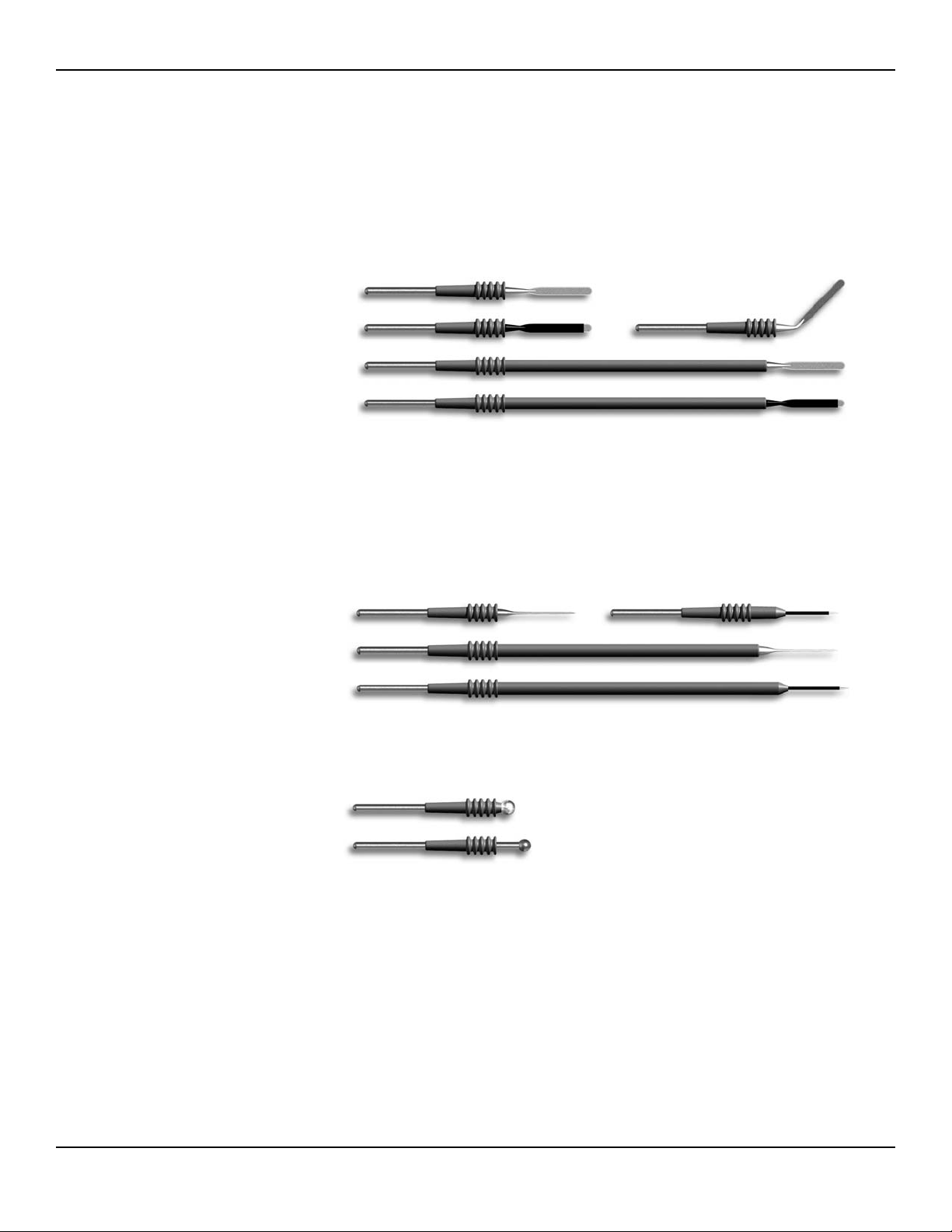
DISPOSABLE ACTIVE ELECTRODES
All electrodes utilize the standard 3/32" stainless steel shafts. All electrodes feature safety grip insulators combining
patient and user safety with easy insertion into and removal from the surgical pencil. All disposable electrodes are
manufactured to the highest standards.
They come individually packaged and are sterile.
Blade Electrodes
ES01 Standard Blade, Box/50
ES37 Modified Blade, Box/25
ES18 Angled Blade Electrode, Box/25
ES04 Extended Blade, Box/25
ES39 Ext. Modified Blade, Box/25
ES55 4" Standard Blade, Box/50
(not pictured)
ES54 4" Modified Blade, Box/25
(not pictured)
Needle Electrodes
ES02 Standard Needle, Box/25
ES38 Modified Needle, Box/25
ES03 Extended Needle, Box/25
ES40 Extended Modified Needle,
Box/25
Ball Electrodes
ES20 3/16" Ball, Box/25
ES21 5/32" Ball, Box/25
B-3User’s Guide • Aaron 950
ES01
ES37 ES18
ES04
ES39
ES02
ES03
ES40
ES20
ES21
ES38
Page 52
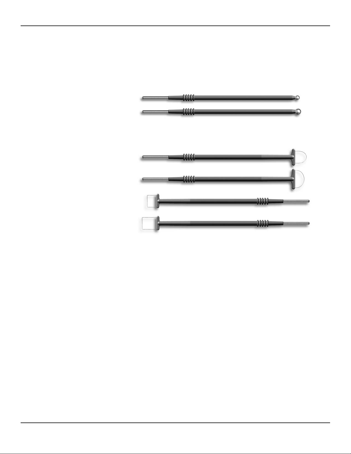
LLETZ ELECTRODES
All Aaron LLETZ Loop and Square electrodes feature tungsten wire for superior shape and integrity throughout the
excision procedure. All loops are packaged with a unique protective shell to prevent damage during shipping. Ball
electrodes are available in 3mm & 5mm sizes for fulguration and desiccation while the needle electrodes are available
for pinpoint coagulation.
Ball Electrodes
ES06 Extended 3mm Ball, Box/5
ES07 Extended 5mm Ball, Box/5
Loop Electrodes
ES08 5mm X 5mm Loop, Box/5
ES09 10mm X 10mm Loop, Box/5
ES10 15mm X 8mm Loop, Box/5
ES11 15mm X 10mm Loop, Box/5
ES12 20mm X 8mm Loop, Box/5
ES13 20mm X 15mm Loop, Box/5
ES31 20mm X 20mm Loop, Box/5
ES42 20mm X 12mm Loop, Box/5
ES43 15mm x 15mm Loop, Box/5
ES44 15mm x 5mm Loop, Box/5
ES45 13mm x 13mm Loop, Box/5
ES46 10mm x 5mm Loop, Box/5
ES47 25mm x 10mm Loop, Box/5
ES51 13mm X 8mm Loop, Box/5
ES52 10mm X 8mm Loop, Box/5
ES53 15mm X 12mm Loop, Box/5
ES41 5mm X 10mm Square, Box/5
ES14 5mm X 5 mm Square, Box/5
ES15 10mm X 4mm Square, Box/5
ES16 10mm X 8mm Square, Box/5
For additional products for LLETZ/LEEP procedures, contact your Aaron Distributor.
B-4 Bovie / Aaron Medical
ES06
ES08
ES46
ES14
All sizes not pictured.
ES41
ES07
Page 53

REUSABLE ACTIVE ELECTRODES
A834 Angled, Fine Needle, Each
A811 Reusable Electrode, Each
A830 Angled, Sharp Electrode, Each
A831 Short Angled, Ball, Each
A832 Short Straight, Ball, Each
A832M Short Straight, Ball, 3/32”, Each
A833 Short Straight, Needle, 3/16”, Each
A835 Long, Straight Ball, Each
A836 Long, Straight Needle, Each
BIPOLAR FORCEPS (REUSABLE)
Reusable Bipolar Forceps are available in micro,
1.0 and 2.0mm tip size and in lengths ranging
from 4.5" to 8". These forceps are guaranteed
for twenty cycles of autoclaving. Reusable Bipolar
cord is also available with quality silicone construction.
A827EU Forceps Cord, Each (not pictured)
A826 5" Straight, Fine, Smooth, Each
A825 5 1/2" Straight, Med., Smooth, Each
A824 5" Curved, Fine, Smooth, Each
A823 7" Curved, Fine, Smooth, Each
A822 7" Straight, Fine, Smooth, Each
A821 7 1/2" Bayonet Med., Smooth, Each
A820 7 1/2" Bayonet Fine, Smooth, Each
A840 4" Tenzel with 5mm Tip, Coated, Each
A841 3 1/2" McPherson Curved with 5mm Tip, Coated, Each
A842 3 1/2" McPherson Straight with 5mm Tip, Coated, Each
A843 4" Tenzel with 5mm Tip, Uncoated, Each
A844 3 1/2" McPherson Curved with 5mm Tip, Uncoated, Each
A845 3 1/2" McPherson Straight with 5mm Tip, Uncoated, Each
B-5User’s Guide • Aaron 950
A826
A825
A824
A823
A822
A821
A820
All sizes and styles not pictured.
A834
A811
A830
A831
A832
A833
A835
A836
A832M
Page 54
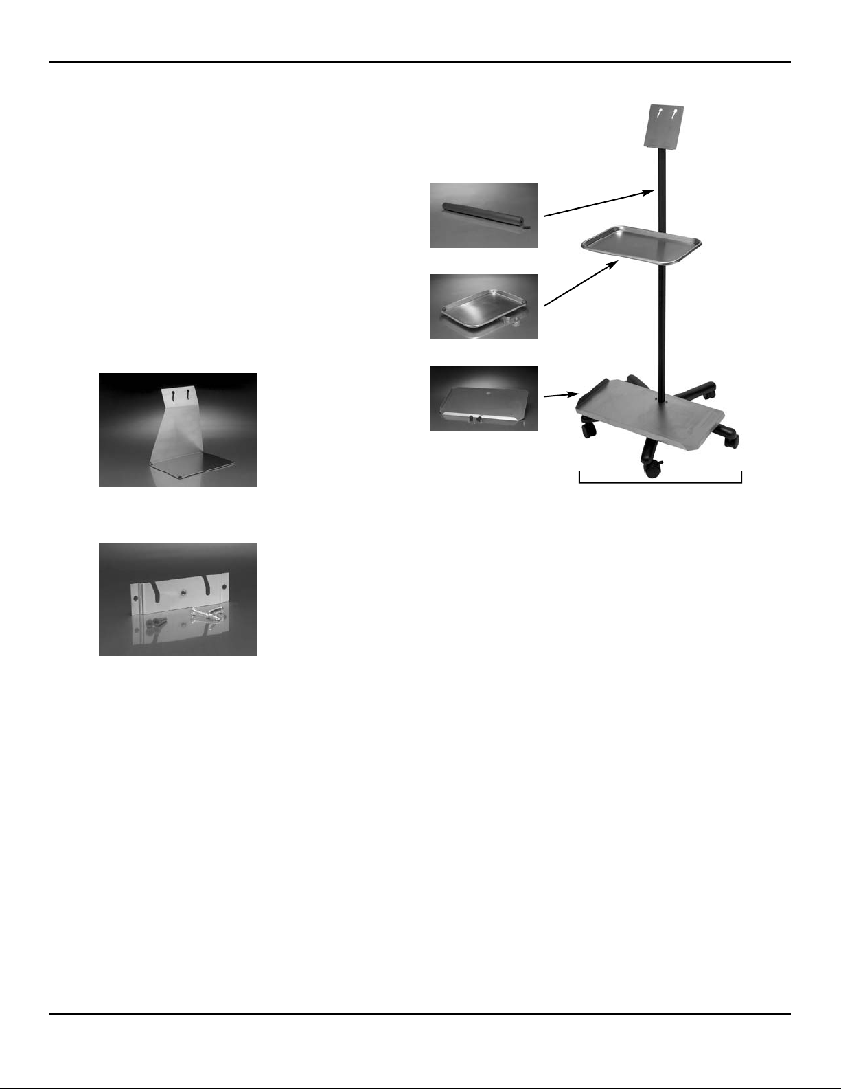
MOUNTING OPTIONS
The Aaron 950 comes with a wall mount kit. A mobile stand is available with
optional instrument tray and smoke evacuator shelf. A stainless steel table top stand
is also available.
A812-C Mobile Stand with Bottom Tray, Top Tray, Clamp,
and 12" Height Extender, Each
A812 Mobile Stand, Each
A812-BTOptional Bottom Tray for Smoke Evacuator, Each
A808-T Optional Top Tray for Instruments, Each
A812-E Optional 12" Height Extender, Each
A813 Stainless Steel Table Top Stand, Each
A837 Replacement Wall Mount Kit, Each
B-6 Bovie / Aaron Medical
A812-C
A812-E
A812-BT
A808-T
A812
(Stand Only)
Page 55

C-1User’s Guide • Aaron 950
WARRANTY
Aaron Medical, a Bovie Company, warrants each product manufactured by it to be free from defects in material and
workmanship under normal use and service for the period(s) set forth below.
Aaron Medical’s obligation under this warranty is limited to the repair or replacement, at its sole option, of any
product, or part thereof, which has been returned to it or its Distributor within the applicable time period shown
below after delivery of the product to the original purchaser, and which examination discloses, to Aaron Medical’s
satisfaction, that the product is indeed, defective.
This warranty does not apply to any product, or part thereof, which has been repaired or altered outside Aaron
Medical’s factory in a way so as, in Aaron Medical’s judgment, to affect its stability or reliability, or which has been
subjected to misuse, neglect, or accident.
The warranty periods for Aaron Medical products are as follows:
• Electrosurgical Generators: Two years from date of shipment
• Mounting Fixtures (all models): Two years from date of shipment
• Footswitches (all models): Ninety days from date of shipment
• Patient Return Electrodes: Shelf life only as stated on packaging
• Sterile Single Use Accessories: Only as stated on packaging
• Handpiece: Only as stated on packaging
Page 56

This warranty is in lieu of all other warranties, express or implied, including without limitation, the warranties of
merchantability and fitness for a particular purpose, and of all other obligations or liabilities on the part of Aaron
Medical.
Aaron Medical neither assumes nor authorizes any other person to assume for it any other liability in connection
with the sale or use of any of Aaron Medical’s products.
Notwithstanding any other provision herein or in any other document or communication, Aaron Medical’s liability
with respect to this agreement and products sold hereunder shall be limited to the aggregate purchase price for the
goods sold by Aaron Medical to the customer.
Aaron Medical disclaims any liability hereunder or elsewhere in connection with the sale of this product, for indirect
or consequential damages.
This warranty and the rights and obligations hereunder shall be construed under and governed by the laws of the
State of Florida, USA.
The sole forum for resolving disputes arising under or relating in any way to this warranty is the District Court of the
County of Pinellas, State of Florida, USA.
Aaron Medical, its dealers, and representatives reserve the right to make changes in equipment built and/or sold by
them at any time without incurring any obligation to make the same or similar changes on equipment previously
built and/or sold by them.
C-2 Bovie / Aaron Medical
 Loading...