

Page 1
1Service Guide • Aaron 1250
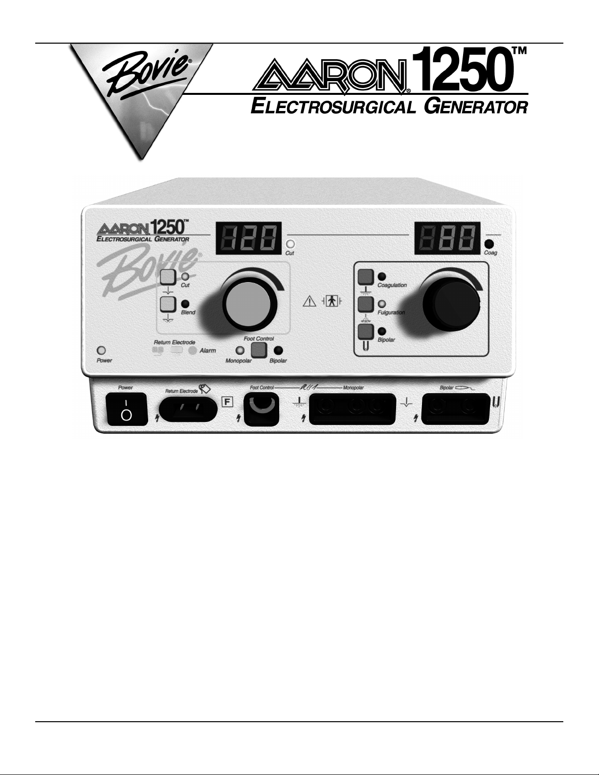
SERVICE GUIDE
Page 2

PREFACE
This Service Guide and the equipment it describes are for qualified technicians who maintain and repair the Aaron
1250 Electrosurgical Generator. Additional User information is available in the Aaron 1250 Electrosurgical Generator
User’s Guide.
This document covers technical descriptions of the Aaron 1250 including its physical appearance, all operator controls and indications, operational specifications, component functional descriptions (module level), diagrams of the
electronic circuits used, and troubleshooting guidelines (with chart comparisons).
The Aaron 1250 was constructed with the highest quality components, and was built in a registered
environment. In the unlikely event that your generator fails within 1 year of purchase date, Bovie / Aaron Medical
will warranty the product and effect factory repairs. Please refer to Appendix A Warranty for what is covered, how
long, and “How to Receive a Return Authorization Number”.
Equipment covered in this manual
Aaron 1250 Electrosurgical Generator (110 VAC Model) A1250
Aaron 1250 Electrosurgical Generator (220 VAC Model) A1250-220
For Information Call
Bovie Aaron Medical • St. Petersburg, FL 33710
U.S. Phone 1-800-537-2790 Fax 1-800-323-1640 • International Phone +1-727-384-2323 Fax +1-727-347-9144
www.aaronmed.com • [email protected]
EU Authorized Representative:
Peter J. Smith Medical Products Marketing
18 Yeates Close
Thame OX9 3AR
United Kingdom
Made in USA
Printed in USA
©2006 Bovie Aaron Medical, A Bovie Company.
All rights reserved.
Contents of this publication may not be reproduced without the written permission of Bovie Aaron Medical.
Bovie Aaron part number, MC-55-039-001 Rev. 3
2 Bovie / Aaron Medical
Page 3

SAFETY PRECAUTIONS WHEN OPERATING THE GENERATOR
The safe and effective use of electrosurgery depends to a large degree on factors solely under the control of the
operator. There is no substitute for a properly trained and vigilant medical staff. It is important that they read,
understand, and follow the operating instructions supplied with this electrosurgical equipment.
To promote the safe use of the Aaron 1250 Electrosurgical Generator, please refer to the User’s Guide for standard
operating precautions.
APPLICABLE SAFETY STANDARDS
CSA C22.2, NO. 601.1 – M90
UL 2601 – 1 – UL
IEC 60601 – 2 – 2 (1998 – 90) CLASS 1 EQUIPMENT, TYPE BF
CENELEC EN 60601 – 1 – 2
FCC PART 15, CLASS A
IEC 60601-1 2nd Edition (1988)
CONVENTIONS USED IN THIS GUIDE
WARNING
Indicates a potentially hazardous situation which, if not avoided, could result in death or serious
injury.
CAUTION
Indicates a hazardous situation which, if not avoided, may result in minor or moderate injury.
NOTICE
Indicates an operating tip, a maintenance suggestion, or a hazard that may result in product
damage.
3Service Guide • Aaron 1250
Page 4

Table of Contents
Preface .....................................................................................................................................2
Safety Precautions when Operating the Generator ...............................................................3
Applicable Safety Standards ...................................................................................................3
Conventions Used in this Guide ...........................................................................................3
List of Figures .........................................................................................................................7
List of Board Drawings and Schematics ................................................................................7
Section 1. The Aaron 1250 Electrosurgical Generator
Functional Description .........................................................................................................10
Unit Description ...................................................................................................................11
Safety Precautions when Repairing the Generator ..............................................................11
General Warnings, Cautions, and Notices ...................................................................11
Active Accessories ..........................................................................................................11
Fire / Explosion Hazards ..............................................................................................12
Generator Electric Shock Hazards ................................................................................12
Servicing ........................................................................................................................13
Cleaning ........................................................................................................................13
Section 2. Controls, Indicators, and Receptacles
Front Panel ............................................................................................................................16
Controls and Indicators Overview .......................................................................................17
Cut and Blend Controls .......................................................................................................18
Coag and Bipolar Controls ..................................................................................................19
Indicators ..............................................................................................................................20
Power Switch and Receptacles ..............................................................................................21
Symbols on the Front Panel .................................................................................................22
Rear Panel .............................................................................................................................23
Symbols on the Rear Panel ..................................................................................................23
Section 3. Technical Specifications
Performance Characteristics .................................................................................................25
Input Power ...................................................................................................................25
Duty Cycle .....................................................................................................................26
Dimensions and Weight ...............................................................................................26
Operating Parameters ....................................................................................................26
Transport and Storage ...................................................................................................26
Audio Volume ...............................................................................................................26
Patient Return Electrode Sensing .................................................................................27
Low Frequency (50–60 Hz) Leakage Current ...............................................................27
High Frequency (RF) Leakage Current .........................................................................27
Standards and IEC Classifications .......................................................................................28
Class I Equipment (IEC 60601-1) ................................................................................28
Type BF Equipment (IEC 60601-1)/Defibrillator Proof ..............................................28
Drip Proof (IEC 60601-2-2) ..........................................................................................28
Electromagnetic Interference ........................................................................................28
Electromagnetic Compatibility (IEC 60601-1-2 and IEC 60601-2-2) ..........................28
Voltage Transients (Emergency Generator Mains Transfer) .........................................28
Output Power Characteristics ..............................................................................................28
Maximum Output for Bipolar and Monopolar Modes ...............................................28
Output Power Curves ...........................................................................................................29
4 Bovie / Aaron Medical
Page 5

Monopolar Cut Curves .................................................................................................29
Monopolar Coag Curves ......................................................................................................31
Bipolar Curves ......................................................................................................................33
Reference Output Waveforms ..............................................................................................34
Section 4. Theory Of Operation
Block Diagram ......................................................................................................................38
Functional Overview of Key Circuits ...................................................................................38
High Voltage DC Supply ......................................................................................................38
Low Voltage DC Supplies ....................................................................................................38
DC Supply Check Circuit ....................................................................................................39
Temperature Sensing Circuit ................................................................................................39
Four Request Activation Sensing Circuits ...........................................................................39
Speaker Circuit .....................................................................................................................39
Patient Return Electrode Sensing Circuit ............................................................................39
RF Amplifier Circuit ............................................................................................................40
Monopolar Select Circuit .....................................................................................................40
Monopolar / Bipolar Select Relays ......................................................................................40
Controls and Indicators .......................................................................................................40
Digital PWM Circuit ............................................................................................................40
System Logic .........................................................................................................................40
Aaron 1250 Control Signal Inputs and Outputs ................................................................41
Section 5. Operating the Aaron 1250
Inspecting the Generator and Accessories ...........................................................................46
Service Personnel Safety .......................................................................................................46
Installation and Placement ...................................................................................................47
Functional (Operational) Checks .........................................................................................47
How to Set Up and Start the Aaron 1250 Unit ..................................................................47
How to Check the Patient Return Electrode Alarm Function ............................................47
How to Check the Bipolar Mode (with Footswitch) ...........................................................48
How to Check the Monopolar Mode (with Footswitch) .....................................................48
How to Check the Monopolar Mode (with Handswitch) ...................................................48
Operating the Unit ...............................................................................................................49
Section 6. Maintenance
Cleaning the Unit ................................................................................................................52
Performing Periodic Inspection ............................................................................................52
Replacing Fuses .....................................................................................................................52
Section 7. Troubleshooting
Recommended Equipment for Troubleshooting .................................................................54
Troubleshooting the Aaron 1250 .........................................................................................54
Inspecting the Generator .....................................................................................................54
Inspecting the Receptacles ....................................................................................................54
Inspecting Internal Components .........................................................................................55
Understanding Error Codes and Audio Tones ...................................................................56
Correcting Common Problems ............................................................................................57
Main Board Test Points ........................................................................................................61
Display Board Test Points .....................................................................................................61
5Service Guide • Aaron 1250
Page 6

Section 8. Repair Policy and Procedures
Responsibility of the Manufacturer .....................................................................................64
Returning the Generator for Service ...................................................................................64
Obtain a Return Authorization Number .............................................................................64
Clean the Generator .............................................................................................................64
Ship the Generator ...............................................................................................................64
Appendix A. Warranty.........................................................................................................65
Appendix B. Board Drawings and Schematics...................................................................67
6 Bovie / Aaron Medical
Page 7

List of Figures
Figure 2-1 Layout of controls, indicators, and receptacles on the front panel ..................16
Figure 2-2 Controls for the Cut and Blend modes ............................................................18
Figure 2-3 Controls for the Coagulation, Fulguration, and Bipolar modes ......................19
Figure 2-4 Indicators for power, return electrodes, and footswitch control .......................20
Figure 2-5 Location of the unit power switch and front panel receptacles ........................21
Figure 2-6 Layout of connectors and controls on the rear panel .......................................23
Figure 3-1 Output power vs. impedance for Cut mode .....................................................29
Figure 3-2 Peak voltage vs. power setting for Cut mode .....................................................29
Figure 3-3 Output power vs. impedance for Blend mode ..................................................30
Figure 3-4 Peak voltage vs. power setting for Blend mode .................................................30
Figure 3-5 Output power vs. impedance for Coagulation mode ........................................31
Figure 3-6 Peak voltage vs. power setting for Coagulation mode .......................................31
Figure 3-7 Output power vs. impedance for Fulguration mode .........................................32
Figure 3-8 Peak voltage vs. power setting for Fulguration mode ........................................32
Figure 3-9 Output power vs. impedance for Bipolar mode ................................................33
Figure 3-10 Peak voltage vs. power setting for Bipolar mode .............................................33
Figure 3-11 Cut mode waveform .........................................................................................34
Figure 3-12 Blend mode waveform .....................................................................................34
Figure 3-13 Coagulation mode waveform ...........................................................................35
Figure 3-14 Fulguration mode waveform ............................................................................35
Figure 3-15 Bipolar mode waveform ...................................................................................36
Figure 4-1 Functional block diagram of the Aaron 1250 system .......................................38
Board Drawings and Schematics
Schematic 1 Main board .....................................................................................................69
Schematic 2 Power Supply ...................................................................................................70
Schematic 3 RF Amplifier Circuit ......................................................................................71
Schematic 4 Request Sense Circuit Hand A ......................................................................72
Schematic 5 Request Sense Circuit Hand B .......................................................................73
Schematic 6 Request Sense Circuit Foot A ........................................................................74
Schematic 7 Request Sense Circuit Foot B .........................................................................75
Schematic 8 Display Board ..................................................................................................76
Schematic 9 Display Logic ...................................................................................................77
Schematic 10 Monopolar Select Circuit .............................................................................78
Schematic 11 Main Printed Circuit Board .........................................................................79
Schematic 12 Display Printed Circuit Boards ....................................................................80
Schematic 13 Relay Printed Circuit Board .........................................................................81
Schematic 14 Final Assembly ..............................................................................................82
Schematic 15 Front Panel Assembly ...................................................................................83
Schematic 16 Back Panel Assembly .....................................................................................84
7Service Guide • Aaron 1250
Page 8

8 Bovie / Aaron Medical
Page 9

THE AARON 1250 ELECTROSURGICAL GENERATOR
This section includes the following information:
Functional Description
Unit Description
Safety precautions when Repairing the Generator
General Warnings, Cautions, and Notices
Active Accessories
Fire/Explosion Hazards
Generator Electric Shock Hazards
Servicing
Cleaning
CAUTION
Read all warnings, cautions, and instructions provided with this generator before using.
Read the instructions, warnings, and cautions provided with electrosurgical accessories before
using. Specific instructions are not included in this manual.
9Service Guide • Aaron 1250
Page 10

FUNCTIONAL DESCRIPTION
The Aaron 1250 is a multipurpose electrosurgical generator for use in physician’s offices and surgi-centers. It provides
unsurpassed performance, flexibility, reliability, and user convenience in one compact package.
The Aaron 1250 Electrosurgical Generator includes digital technology. This new technology is evident in the selfchecking circuitry and error code readouts. The unit offers monopolar and bipolar electrosurgical operations.
The following are Aaron 1250 key advantages and benefits.
Power Capabilities Up to 120 watts of Pure Cut @ 500 Ω.
Up to 90 watts of Blend @ 800 Ω.
Up to 80 watts of Coagulation @ 1000 Ω.
Up to 40 watts of Fulguration @ 1000 Ω.
Up to 30 watts of Bipolar @ 200 Ω.
Two Levels of Coagulation: Pinpoint coagulation provides precise control of bleeding
Pinpoint Coagulation and Fulguration in localized areas.
Fulguration provides greater control of bleeding in highly
vascular tissue over broader tissue surface areas.
Return Electrode Monitoring System The unit incorporates a return electrode contact quality
monitoring system (RECQMS). This system determines
the type of patient return electrode attached (single plate
or split plate).
It also continuously monitors the contact impedance
between the patient and the split plate patient return
electrode.
Contact impedance is only monitored when approved split
plate patient return electrodes are used.
Memory The generator automatically powers up to the last modes
selected, and previously set power settings.
Floating RF Output This minimizes the potential of alternate site burns.
Standard Front Panel Connectors These connectors accept the latest monopolar and bipolar
instruments.
Self Diagnostics These diagnostics continually monitor the unit to ensure
proper performance.
Whenever they detect a problem, medical personnel
receive audible and visual alarm responses, and the output
is suspended until the alarm condition is cleared.
10 Bovie / Aaron Medical
Page 11

UNIT DESCRIPTION
The Aaron 1250 electrosurgical generator is a self-contained unit, consisting of the main enclosure and power cord.
The main components incorporated in the generator include:
• FRONT PANEL COMPONENTS Power switch; two dials for controlling power output; membrane switches for
selecting modes; receptacles for connecting electrosurgical accessories; and indicators that show the current settings
and patient return electrode status.
• REAR PANEL COMPONENTS Volume control; footswitch receptacle; power cable receptacle and fuse holder;
equipotential grounding lug; and remote accessory receptacle.
• INTERNAL COMPONENTS Display board; main board; pad sensing module; speaker board; and relay board.
SAFETY PRECAUTIONS WHEN REPAIRING THE GENERATOR
Before servicing the Aaron 1250 Generator it is important that you read, understand, and follow the instructions
supplied with it. Also, be familiar with any other equipment used to install, test, adjust, or repair this generator.
General Warnings, Cautions, and Notices
WARNINGS
Use the generator only if the self-test has been completed as described. Otherwise, inaccurate
power outputs may result.
The instrument receptacles on this generator are designed to accept only one instrument at a
time. Do not attempt to connect more than one instrument at a time into a given receptacle.
Doing so will cause simultaneous activation of the instruments.
CAUTIONS
Do not stack equipment on top of the generator or place the generator on top of electrical
equipment. These configurations are unstable and / or do not allow adequate cooling.
Provide as much distance as possible between the electrosurgical generator and other electronic
equipment (such as monitors). An activated electrosurgical generator may cause electrical
interference with them.
Do not turn the activation tone down to an inaudible level. The activation tone alerts the surgical
team when an accessory is active.
NOTICES
If required by local codes, connect the generator to the hospital equalization (grounding) connector
with an equipotential cable.
Connect the power cord to a wall receptacle having the correct voltage. Otherwise, product damage may result.
Active Accessories
WARNINGS
Shock Hazard
– Do not connect wet accessories to the generator.
Shock Hazard
– Ensure that all accessories and adapters are correctly connected and that no
metal is exposed.
11Service Guide • Aaron 1250
Page 12

CAUTIONS
Accessories must be connected to the proper receptacle type. In particular, bipolar accessories
must be connected to the Bipolar Instrument receptacle only. Improper connection may result in
inadvertent generator activation or a Contact Quality Monitor alarm.
Set power levels to the lowest setting before testing an accessory.
NOTICE
During Bipolar Electrosurgery, do not activate the generator until the forceps have made contact
with the patient. Product damage may occur.
Fire / Explosion Hazards
WARNINGS
Explosion Hazard
– Do not install the generator in the presence of flammable anesthetics, gases,
liquids, or objects.
Fire Hazard
– Do not place active accessories near or in contact with flammable materials (such
as gauze or surgical drapes). Electrosurgical accessories that are activated or hot from use can
cause a fire. Use a holster to hold electrosurgical accessories safely away from personnel and
flammable materials.
Fire Hazard
– Do not use extension cords.
Fire Hazard
– For continued protection against fire hazard, replace fuses only with fuses of the
same type and rating as the original fuse.
Generator Electric Shock Hazards
WARNINGS
Connect the generator power cord to a properly grounded receptacle. Do not use power plug
adapters.
Do not connect a wet power cord to the generator or to the wall receptacle.
To allow stored energy to dissipate after power is disconnected (caps discharge) wait at least five
minutes before replacing parts.
Always turn off and unplug the generator before cleaning.
Do not touch any exposed wiring or conductive surfaces while the generator is disassembled and
energized. Never wear a grounding strap when working on an energized generator.
When taking troubleshooting measurements use appropriate precautions such as using isolated
tools and equipment, using the “one hand rule,” etc.
Potentially lethal AC and DC voltages are present in the AC line circuitry, high voltage DC circuitry,
and associated mounting and heat sink hardware described in this manual. These potentials are
not isolated from the AC line. Take appropriate precautions when testing and troubleshooting this
area of the generator.
High frequency, high voltage signals that can cause severe burns are present in the RF output
stage and in the associated mounting and heat sink hardware. Take appropriate precautions when
testing and troubleshooting this area of the generator.
12 Bovie / Aaron Medical
Page 13

Servicing
CAUTION
Read all warnings, cautions, and instructions provided with this generator before servicing.
The generator contains electrostatic-sensitive components. When repairing the generator, work at
a static-control workstation. Wear a grounding strap when handling electrostatic-sensitive components, except when working on an energized generator. Handle circuit boards by their nonconductive edges. Use an anti-static container for transport of electrostatic-sensitive components and circuit boards.
NOTICE
After installing a new low voltage power supply, verify that the voltages are correct.
Cleaning
NOTICE
Do not clean the generator with abrasive cleaning or disinfectant compounds, solvents, or other
materials that could scratch the panels or damage the generator.
13Service Guide • Aaron 1250
Page 14

14 Bovie / Aaron Medical
Page 15

CONTROLS, INDICATORS, AND RECEPTACLES
This section describes the front and rear panels, including all controls, indicators, receptacles, the fuse drawer,
and ports.
15Service Guide • Aaron 1250
Page 16
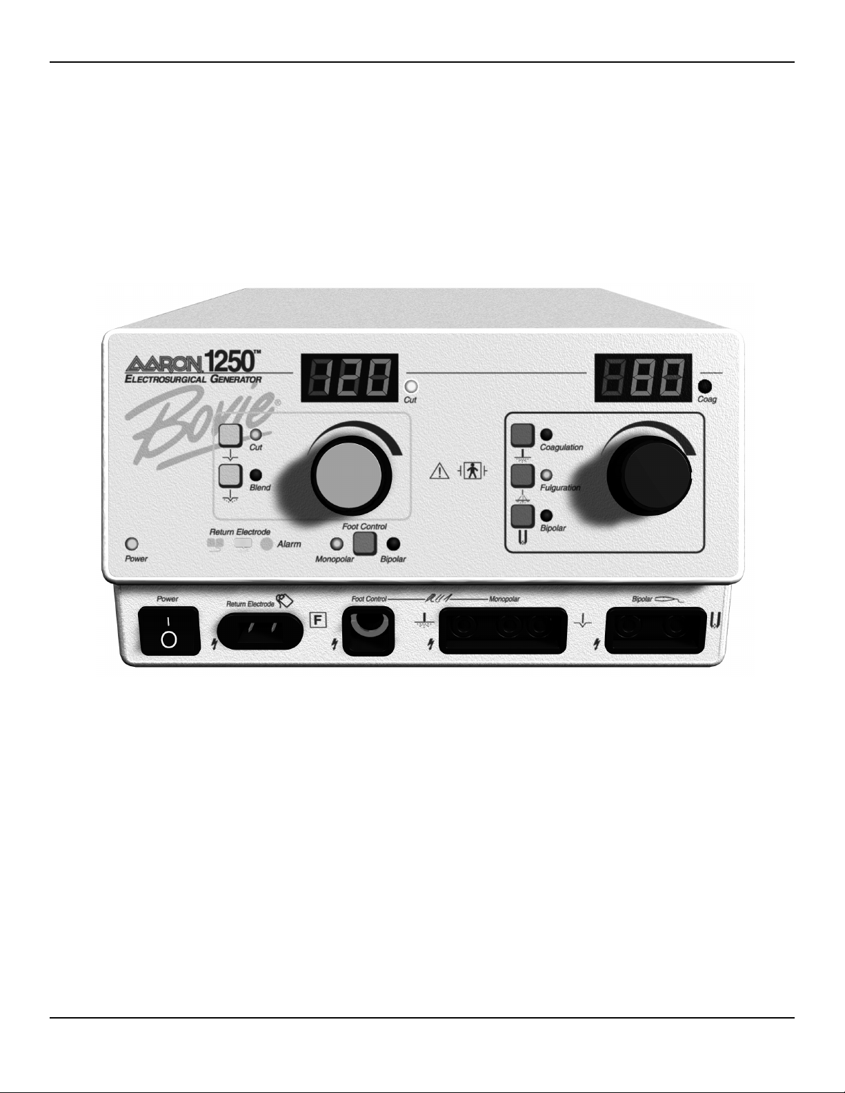
FRONT PANEL
Figure 2-1 Layout of controls, indicators, and receptacles on the front panel
16 Bovie / Aaron Medical
Page 17

CONTROLS AND INDICATORS OVERVIEW
Users may control most Aaron 1250 functions from the front panel. Each Control is plainly marked and
colored on the front panel for quick reference. Volume control and a footswitch connector are located on
the rear panel.
Normal operations involve activating the generator with either a front connected handswitch OR a rearconnected footswitch. The following components are the User Interface for the Aaron 1250 Electrosurgical
Generator.
Power Switch The rocker ON / OFF switch on the lower left corner
allows the Aaron 1250 to be shut off when the unit is not
in use.
Membrane Function Switches The front panel overlay contains 6 membrane function
switches (sometimes called matrix switches). There is a
membrane switch dedicated for each operational mode.
These switches toggle the unit between mode settings.
Power Control Knob These rotary knobs allow you to select the desired
RF power level for all modes of operation. The Power
Control Knobs move at a graduated 1 watt per notch
(incrementally).
Watts Display A & B (Cut and Coag) These large Power Output Displays report the generator’s
output power setting from 1 to 120 watts in 1 watt
increments (at the rated load). During operation, the
numeral output of the display gives the surgeon an
indication of available generator power.
Visual LED Indictors Mode LEDs indicate the mode setting.
The YELLOW indicators and controls indicate cutting
and blending operations. A yellow field LED indicates that
either a Cut or Blend mode is activated.
The BLUE indicators and controls indicate Coagulation,
Fulguration, and Bipolar operation. The blue field LED
indicates either Coagulation, Fulguration or Bipolar mode
is activated.
The Footswitch Control LED Indicator indicates which
mode the footswitch is presently in.
Monopolar footswitch control allows the user to activate
the monopolar mode when using footswitch controlled
accessories.
Bipolar footswitch control allows the user to activate the
bipolar mode.
17Service Guide • Aaron 1250
Page 18
Visual LED Indictors A Return Electrode Indicator displays which type of
patient Return Electrode is attached to the patient. It also
has an associated audio alarm that sounds when a patient
return electrode is not detected during activation.
Audible Indicators An activation tone sounds whenever the Aaron 1250
Electrosurgical Generator is activated. The volume may be
adjusted up or down on the rear of the unit.
An Alarm Siren sounds during all alarm conditions. The
volume of this alarm cannot be adjusted.
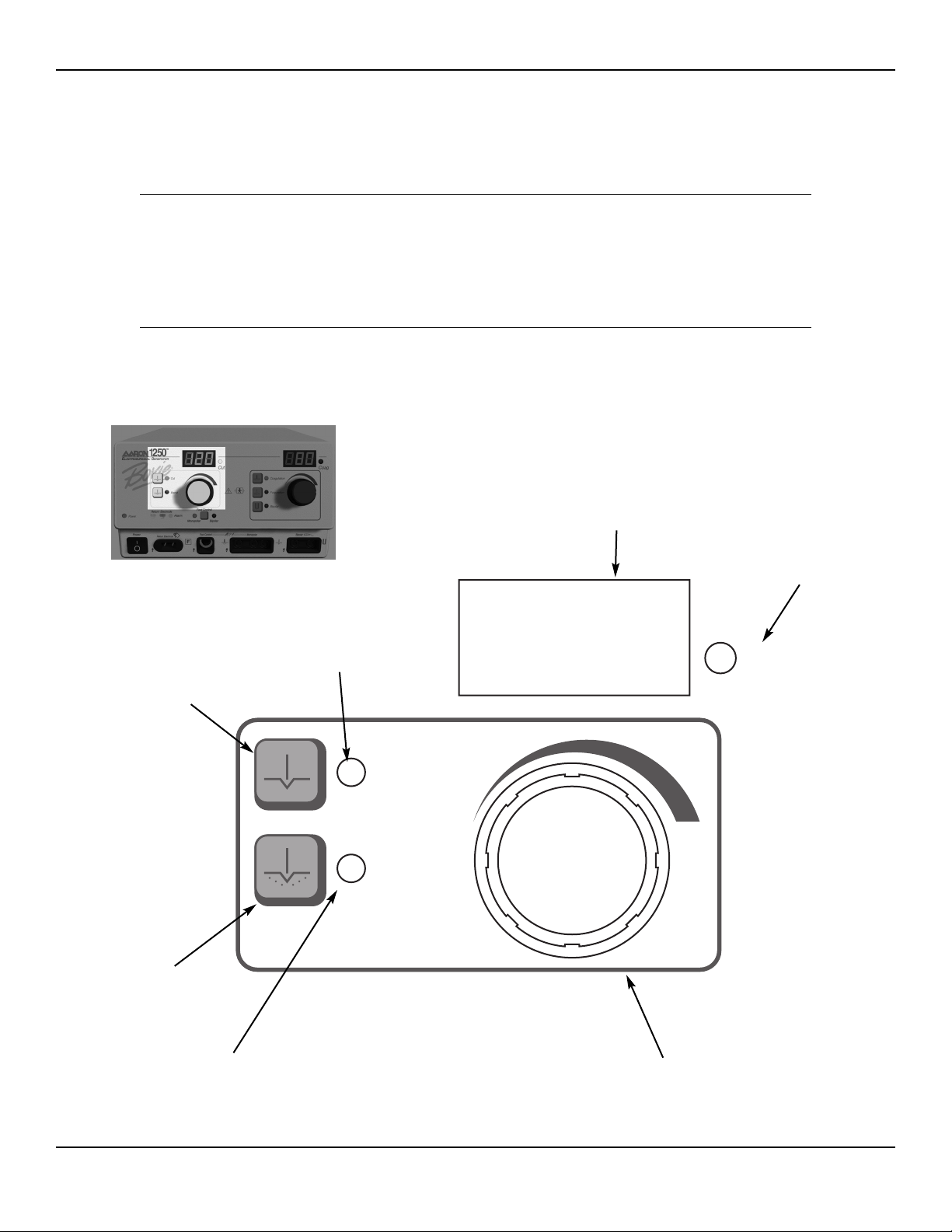
CUT AND BLEND CONTROLS
Figure 2-2 Controls for the Cut and Blend modes
18 Bovie / Aaron Medical
Cut
Blend
Cut
Cut Indicator
Illuminates when
Pure Cut Mode
is selected.
Cut and Blend
Activation Indicator
Illuminates when you
activate either Pure Cut
or Blend Mode.
Cut and Blend Power Control Dial
Increases or decreases the Cut or Blend
power output in increments of 1 watt.
Cut and Blend
Power Display (watts)
Indicates the power set for the
Pure Cut or Blend Mode.
Blend Indicator
Illuminates when
Blend Mode
is selected.
Cut Selector
When pressed, selects
the Pure Cut Mode.
Blend Selector
When pressed, selects
the Blend Mode.
Page 19
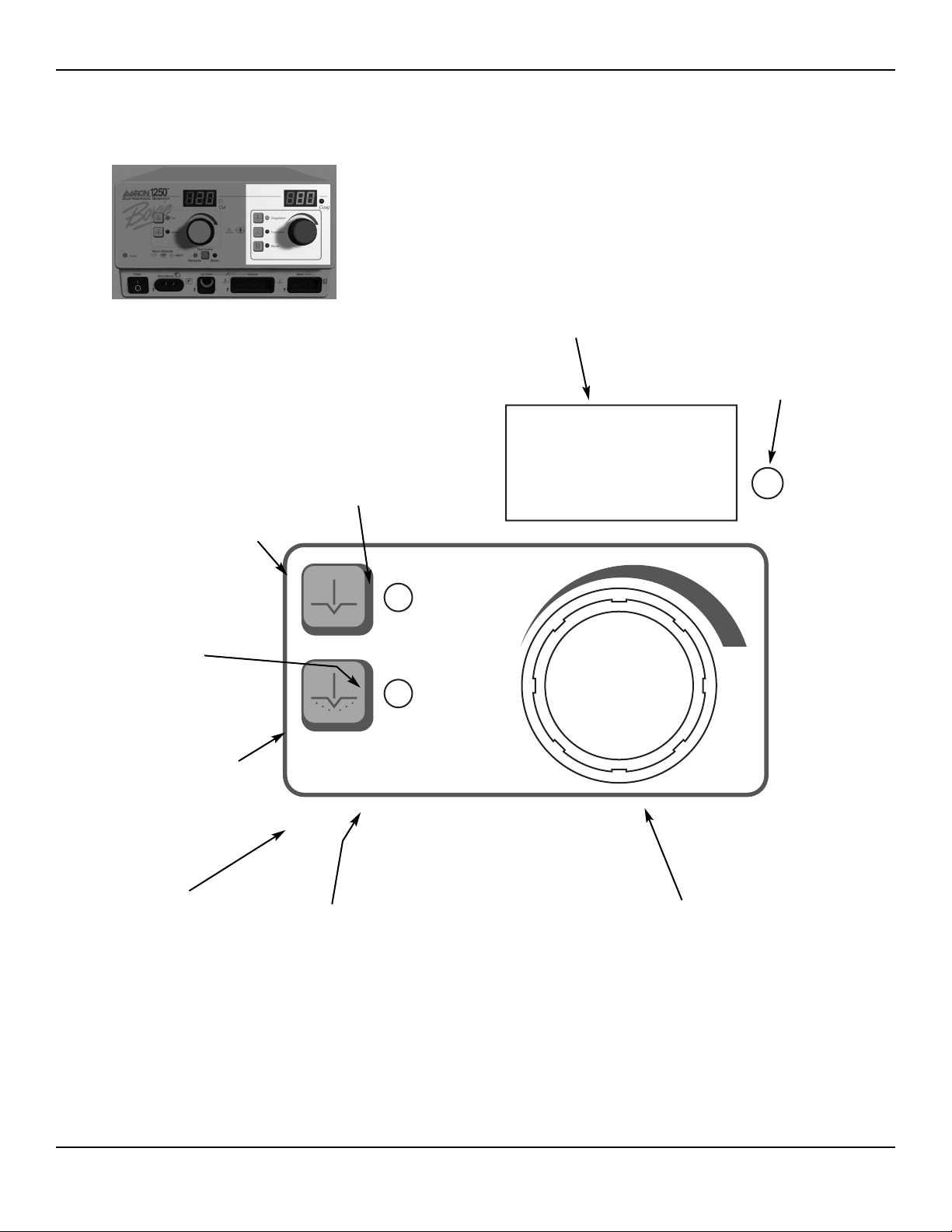
COAG AND BIPOLAR CONTROLS
Figure 2-3 Controls for the Coagulation, Fulguration, and Bipolar modes
19Service Guide • Aaron 1250
Cut
Blend
Cut
Coag and Bipolar
Activation Indicator
Illuminates when you
activate Coagulation,
Fulguration, or
Bipolar Mode.
Coag and Bipolar Power Control Dial
Increases or decreases the Coag or Bipolar
power output in increments of 1 watt.
Coag and Bipolar
Power Display (watts)
Indicates the power set for
any Coag or Bipolar Mode.
Coagulation Indicator
Illuminates when
Coagulation Mode
is selected.
Fulguration Indicator
Illuminates when
Fulguration Mode
is selected.
Bipolar Indicator
Illuminates when
Bipolar Mode
is selected.
Coagulation Selector
When pressed, selects
the Coagulation Mode.
Fulguration Selector
When pressed, selects
the Fulguration Mode.
Bipolar Selector
When pressed, selects
the Bipolar Mode.
Page 20
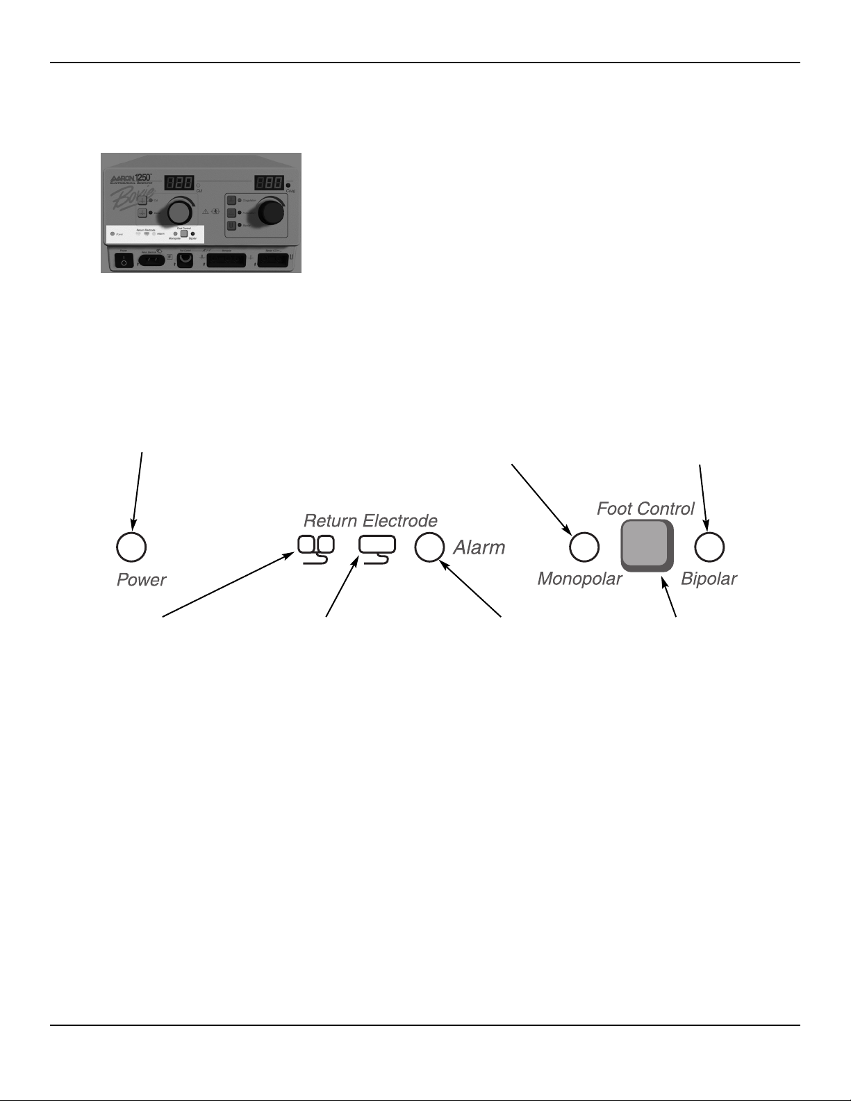
INDICATORS
Figure 2-4 Indicators for power, return electrodes, and footswitch control
20 Bovie / Aaron Medical
Power Indicator
Illuminates when
the unit is on.
Split-Plate Patient Return
Electrode Indicator
Illuminates when the system
detects a split plate.
Single Plate Patient Return
Electrode Indicator
Illuminates when the system
detects a single plate.
Monopolar Footswitch
Control Indicator
Illuminates when monopolar
footswitch control is selected.
Bipolar Footswitch
Control Indicator
Illuminates when bipolar
footswitch control is selected.
Patient Return Electrode
Alarm Indicator
Illuminates when the system
detects a patient return
electrode alarm condition.
Footswitch Control
Selector
When pressed, toggles
between monopolar
and bipolar foot control.
Page 21
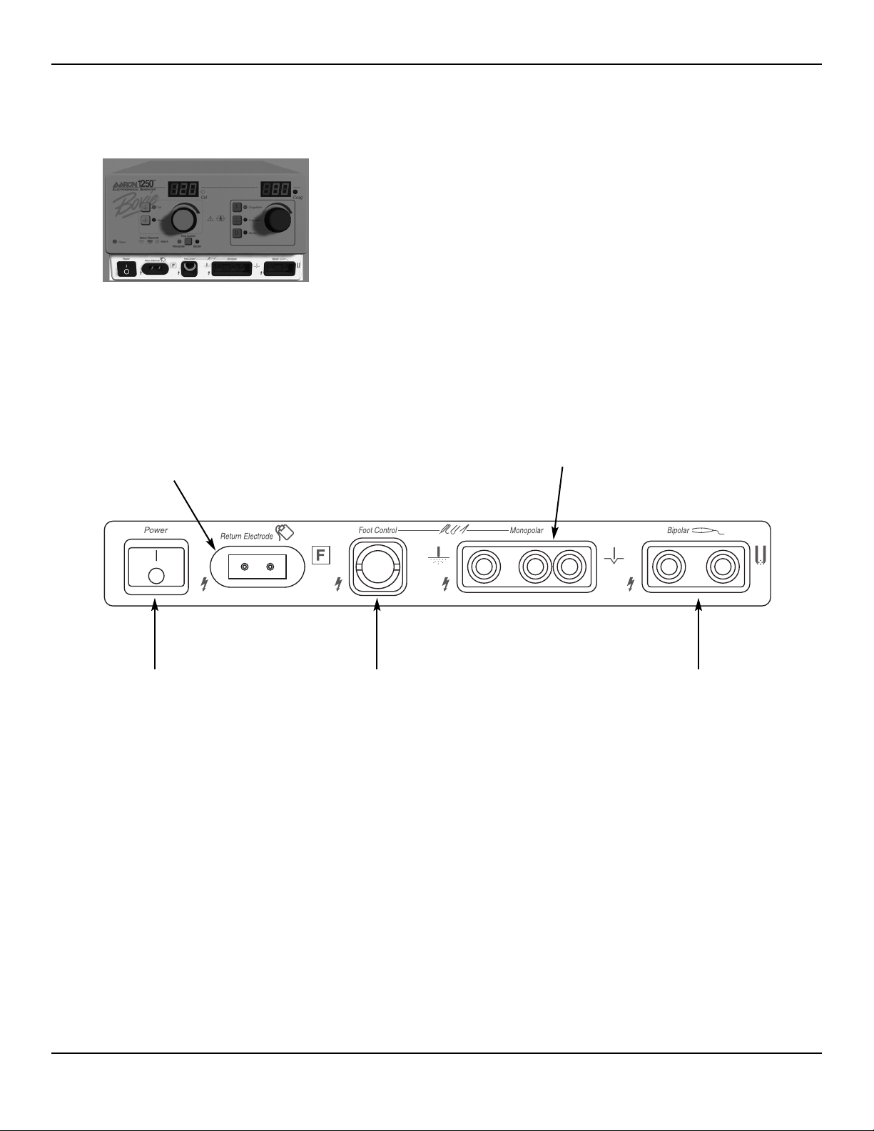
POWER SWITCH AND RECEPTACLES
Figure 2-5 Location of the unit power switch and front panel receptacles
21Service Guide • Aaron 1250
Power On/Off Switch
Turns the unit on or off.
Monopolar Footswitching Receptacle
Accepts cables or adapters equipped
with standard (Bovie #12) active plugs.
Connect footswitching accessories.
Bipolar Receptacle
Accepts standard cables
for bipolar handpieces.
Patient Return Electrode
Receptacle
Accepts a standard patient
return electrode plug.
Monopolar Handswitching Receptacle
Accepts standard three-pin handpieces.
Connect handswitching accessories.
Page 22
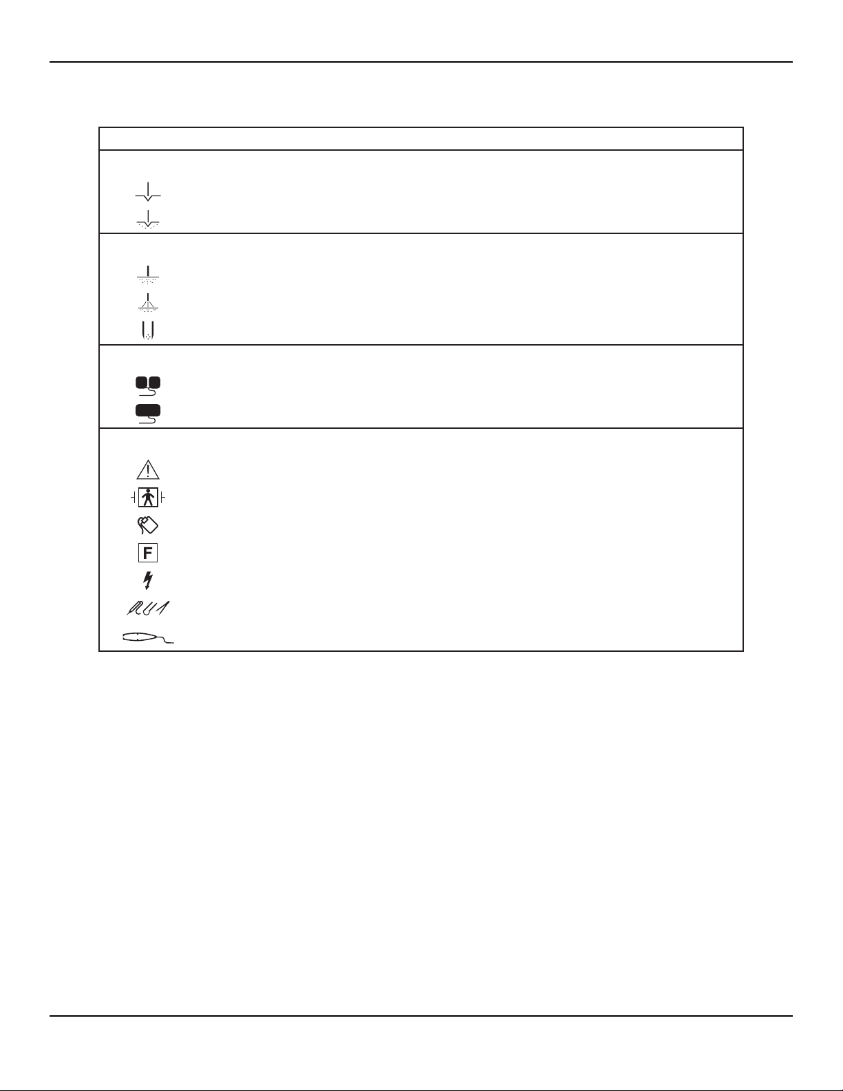
SYMBOLS ON THE FRONT PANEL
22 Bovie / Aaron Medical
SYMBOLS DESCRIPTION
Cut Controls
Cut Mode
Blend Mode
Coag Controls
Coagulation Mode
Fulguration Mode
Bipolar Mode
Indicators
Split Plate Return Electrode
Single Plate Return Electrode
Power Switch and Handpiece Connectors
Read instructions before use.
Type BF (Defibrillator – Proof) Equipment
Patient Return Electrode
RF isolated – patient connections are isolated from earth at high frequency.
Caution High Voltage
Monopolar Output
Bipolar Output
Page 23
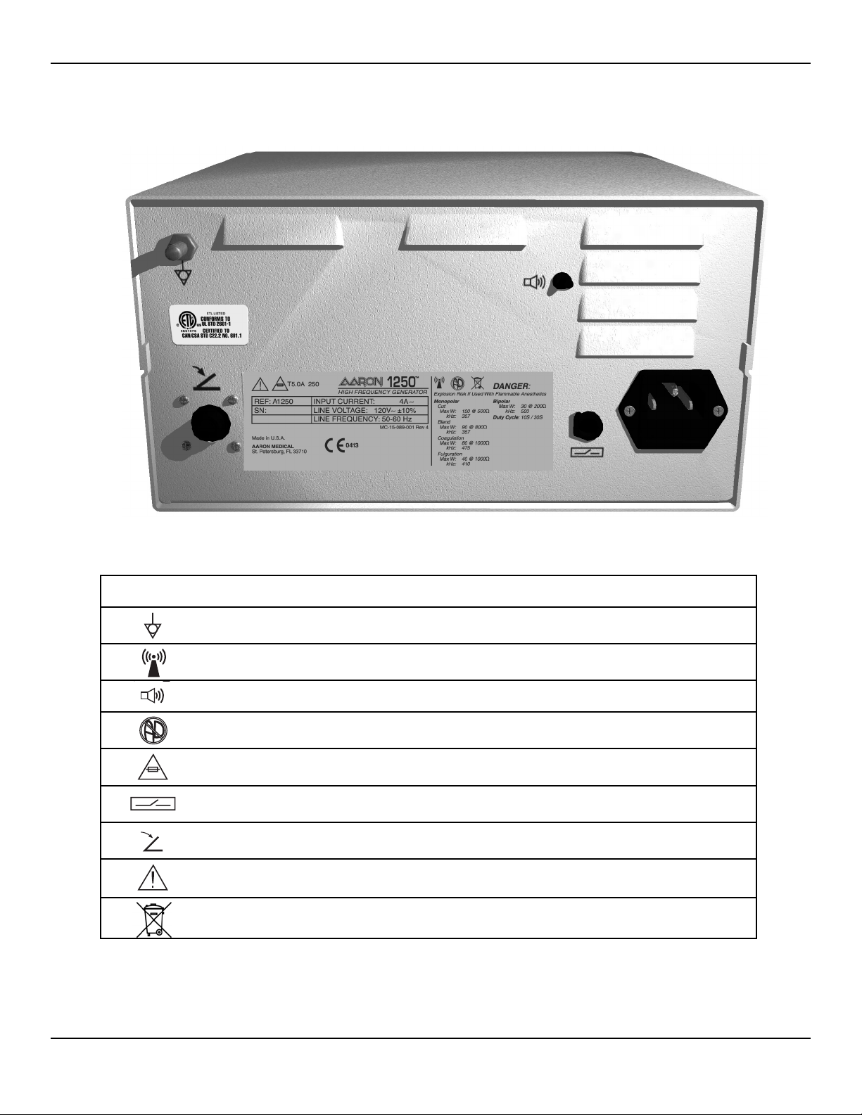
REAR PANEL
Figure 2-6 Layout of connectors and controls on the rear panel
SYMBOLS ON THE REAR PANEL
23Service Guide • Aaron 1250
SYMBOLS DESCRIPTION
Equipotential Ground Stud
Non-ionizing Radiation
Volume Control
Danger
- Explosion Risk If Used With Flammable Anesthetics.
Fuse Enclosed
Relay Connector
Footswitch Input Jack
Read Instructions Before Use
Do not dispose of this device in the unsorted municipal waste stream.
Page 24

24 Bovie / Aaron Medical
Page 25

TECHNICAL SPECIFICATIONS
All specifications are nominal and subject to change without notice. A specification referred to as “typical” is within ±
20% of a stated value at room temperature (25° C / 77° F) and a nominal input power voltage.
PERFORMANCE CHARACTERISTICS
Input Power
25Service Guide • Aaron 1250
110-120 Volt 220-240 Volt
Mains line frequency range (nominal):
60 Hz
Mains line frequency range (nominal):
50 Hz
Power consumption: 540 VA Power consumption: 540 VA
Fuses (2): 5A (Slow Blow) Fuses (2): 3.15A (Slow Blow)
Page 26

Duty Cycle
Under maximum power settings and rated load conditions (Pure cut, 120 watt @ 500 Ω load), the generator is
suitable for activation times of 10 seconds on, 30 seconds off for one hour.
NOTICE
The internal temperature of the unit is constantly being monitored. If the temperature rises above
85° an alarm sounds, the system displays an error code, and the system disables output power.
Dimensions and Weight
Operating Parameters
Transport and Storage
Audio Volume
The audio levels stated below are for activation tones (bipolar, cut, and coag) and alarm tones (return electrode and
system alarms) at a distance of one meter. Alarm tones meet the requirements for IEC 60601-2-2.
Activation Tone
26 Bovie / Aaron Medical
Width
........................................26 cm (10.25 in.)
Depth
.........................................30.5 cm (12 in.)
Height
......................................15.2 cm (6 in.)
Weight
.......................................< 6.5 kg (< 14 lbs)
Ambient temperature range
10° to 40° C (50° to 104° F)
Relative humidity
30% to 75%, noncondensing
Atmospheric pressure
700 to 1060 millibars
Warm-up time
If transported or stored at temperatures outside the operating temperature range,
allow one hour for the generator to reach room temperature before use.
Ambient temperature range
-34° to 65° C (-29° to 149° F)
Relative humidity
10% to 100%, condensing
Atmospheric pressure
500 to 1060 millibars
Volume (adjustable)
45 to 65 dBa
Frequency
Cut: 1 kHz
Blend: 1 kHz
Coagulation: 2 kHz
Fulguration: 2 kHz
Bipolar: 2 kHz
Duration
Continuous while the generator is activated
Page 27

Alarm Tone
Patient Return Electrode Sensing
The system presents audible and visible alarms when it senses no patient return electrode:
• When a fault condition occurs, the alarm indicator flashes red, an alarm tone sounds, and the system disables out
put power.
• The red LED alarm indicator remains illuminated until you correct the condition that caused the alarm condition.
• Activation attempts during an alarm condition result in an audio alarm.
• When the alarm condition is resolved, the green single or split-plate indicator will illuminate.
• The system measures the return electrode sensing current according to IEC 60601-1.
Low Frequency (50–60 Hz) Leakage Current
High Frequency (RF) Leakage Current
27Service Guide • Aaron 1250
Volume (not adjustable)
70 dB ± 5dBa
Frequency
2 kHz for 1/2 second, then1 kHz for 1/2 second
Duration
2 seconds
Single Plate
Trip resistance: 0 Ω to 5 Ω ± 3 Ω
Continuous measurement:
Once the system establishes the single-plate electrode resistance, a change of
20 Ω ± 5 Ω in resistance will cause an alarm. When the alarm condition exists,
the system deactivates output power.
Split Plate
Trip resistance: 10 Ω ± 5 Ω to 135 Ω ± 10 Ω
Continuous measurement:
Once the system establishes the split-plate electrode resistance, a change
of 40% in resistance will cause an alarm. When the alarm condition exists,
the system deactivates output power.
Enclosure source current, ground open
< 500 μA
Source current, patient leads, all outputs
Normal polarity, intact ground: < 50 μA
Normal polarity, ground open: < 50 μA
Reverse polarity, ground open: < 50 μA
Sink current at high line, all inputs
< 50 μA
Bipolar RF leakage current
< 39 mA
rms
Monopolar RF leakage current (additional tolerance)
< 150 mA
rms
Page 28

STANDARDS AND IEC CLASSIFICATIONS
Class I Equipment (IEC 60601-1)
Accessible conductive parts cannot become live in the event of a basic insulation failure because of the way in which
they are connected to the protective earth conductor.
Type BF Equipment (IEC 60601-1) / Defibrillator Proof
The Aaron 1250 Electrosurgical Generator provides a high degree of protection against electric shock,
particularly regarding allowable leakage currents. It is type BF equipment. Patient connections are isolated
from earth and resist the effects of defibrillator discharge.
Drip Proof (IEC 60601-2-2)
The generator enclosure is constructed so that liquid spillage in normal use does not wet electrical insulation or other
components which, when wet, are likely to affect adversely the safety of the generator.
Electromagnetic Interference
When other equipment is placed on or beneath an activated Bovie Aaron Medical electrosurgical generator, the
Aaron 1250 Electrosurgical Generator operates without interference. The generator minimizes electromagnetic interference to video equipment used in the operating room.
Electromagnetic Compatibility (IEC 60601-1-2 and IEC 60601-2-2)
The Aaron 1250 Electrosurgical Generator complies with the appropriate IEC 60601-1-2 and IEC 60601-2-2
specifications regarding electromagnetic compatibility.
Voltage Transients (Emergency Generator Mains Transfer)
The Aaron 1250 Electrosurgical Generator operates in a safe manner when the transfer is made between line AC and
an emergency generator voltage source.
OUTPUT POWER CHARACTERISTICS
Maximum Output for Bipolar and Monopolar Modes
Power readouts agree with actual power into rated load to within 20% or 5 watts, whichever is greater.
* an indication of a waveform’s ability to coagulate bleeders without a cutting effect
28 Bovie / Aaron Medical
Mode Output Power Output Frequency Repetition Rate Vp-p max
Crest Factor*
(Rated Load)
Cut 120 W @ 500 Ω 357 kHz ± 50 kHz N / A 2.5 KV 2.9 ± 20%
Blend 90 W @ 800 Ω 357 kHz ± 50 kHz 30 kHz ± 5 kHz 3.5 KV 3.3 ± 20%
Coagulation 80 W @ 1000 Ω 425 kHz – 494 kHz 57 kHz ± 5 kHz 4.5 KV 5.5 ± 20%
Fulguration 40 W @ 1000 Ω 410 kHz ± 50 kHz 25 kHz ± 5 kHz 6.5 KV 7.7 ± 20%
Bipolar 30 W @ 200 Ω 506 kHz – 570 kHz 32 kHz ± 5 kHz 2.0 KV 6.9 ± 20%
Page 29
OUTPUT POWER CURVES
The curves that follow depict the changes for each mode at specific power settings.
Monopolar Cut Curves
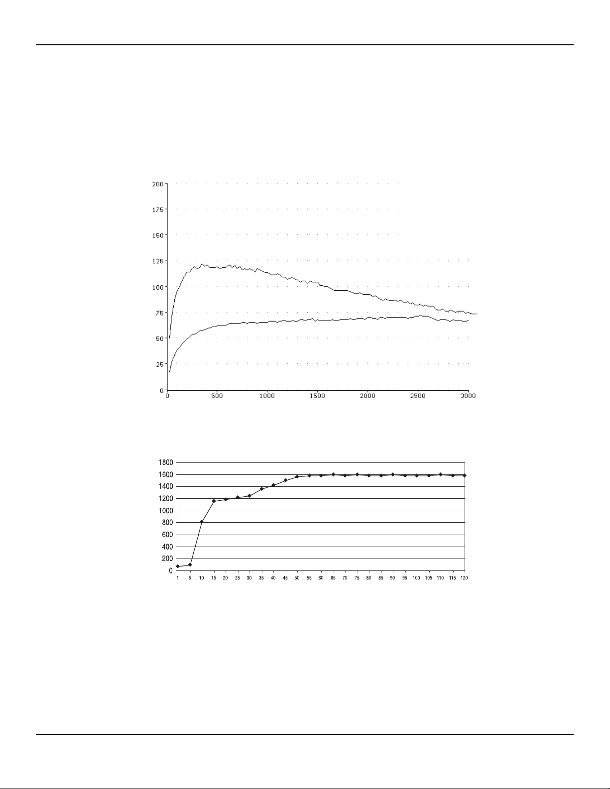
These measurements were taken using short (< 0.5 meter) leads. For each output power vs. impedance curve, the
upper curve represents readings taken at full power; the lower curve, readings taken at half power.
Figure 3 – 1 Output power versus impedance for Cut mode
Figure 3 – 2 Peak voltage vs. power setting for Cut mode
29Service Guide • Aaron 1250
Load Resistance (ohms)
Output Power Setting (watts)
Open Circuit Peak Voltage (volts) Output Power (watts)
Page 30
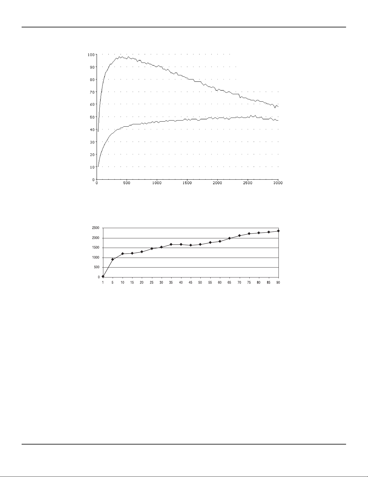
Figure 3 – 3 Output power versus impedance for Blend mode
Figure 3 – 4 Peak voltage vs. power setting for Blend mode
30 Bovie / Aaron Medical
Load Resistance (ohms)
Output Power (watts)Open Circuit Peak Voltage (volts)
Output Power Setting (watts)
Page 31
Monopolar Coag Curves
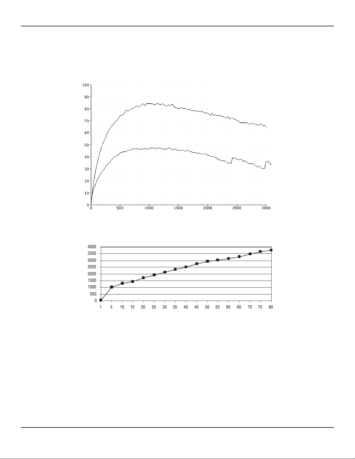
These measurements were taken using short (< 0.5 meter) leads.
Figure 3 – 5 Output power versus impedance for Coagulation mode
Figure 3 – 6 Peak voltage vs. power setting for Coagulation mode
31Service Guide • Aaron 1250
Load Resistance (ohms)
Output Power Setting (watts)
Open Circuit Peak Voltage (volts)
Output Power (watts)
Page 32
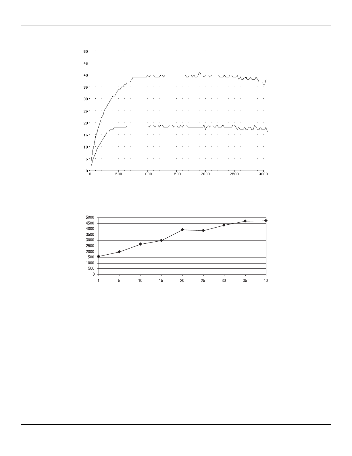
Figure 3 – 7 Output power versus impedance for Fulguration mode
Figure 3 – 8 Peak voltage vs. power setting for Fulguration mode
32 Bovie / Aaron Medical
Load Resistance (ohms)
Output Power (watts)Open Circuit Peak Voltage (volts)
Output Power Setting (watts)
Page 33
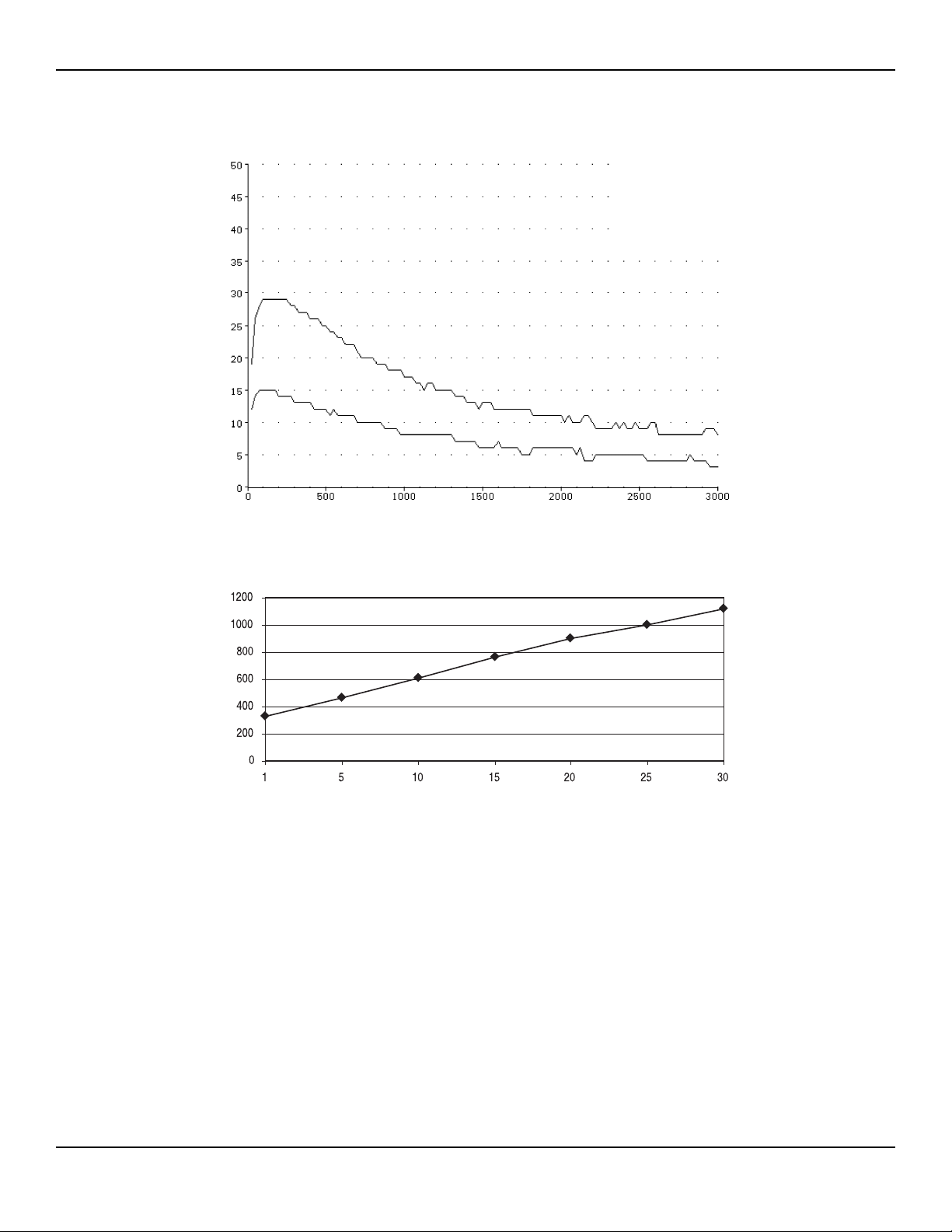
Bipolar Curves
Figure 3 – 9 Output power versus impedance for Bipolar mode
Figure 3 – 10 Peak voltage vs. power setting for Bipolar mode
33Service Guide • Aaron 1250
Output Power (watts)Open Circuit Peak Voltage (volts)
Load Resistance (ohms)
Output Power Setting (watts)
Page 34
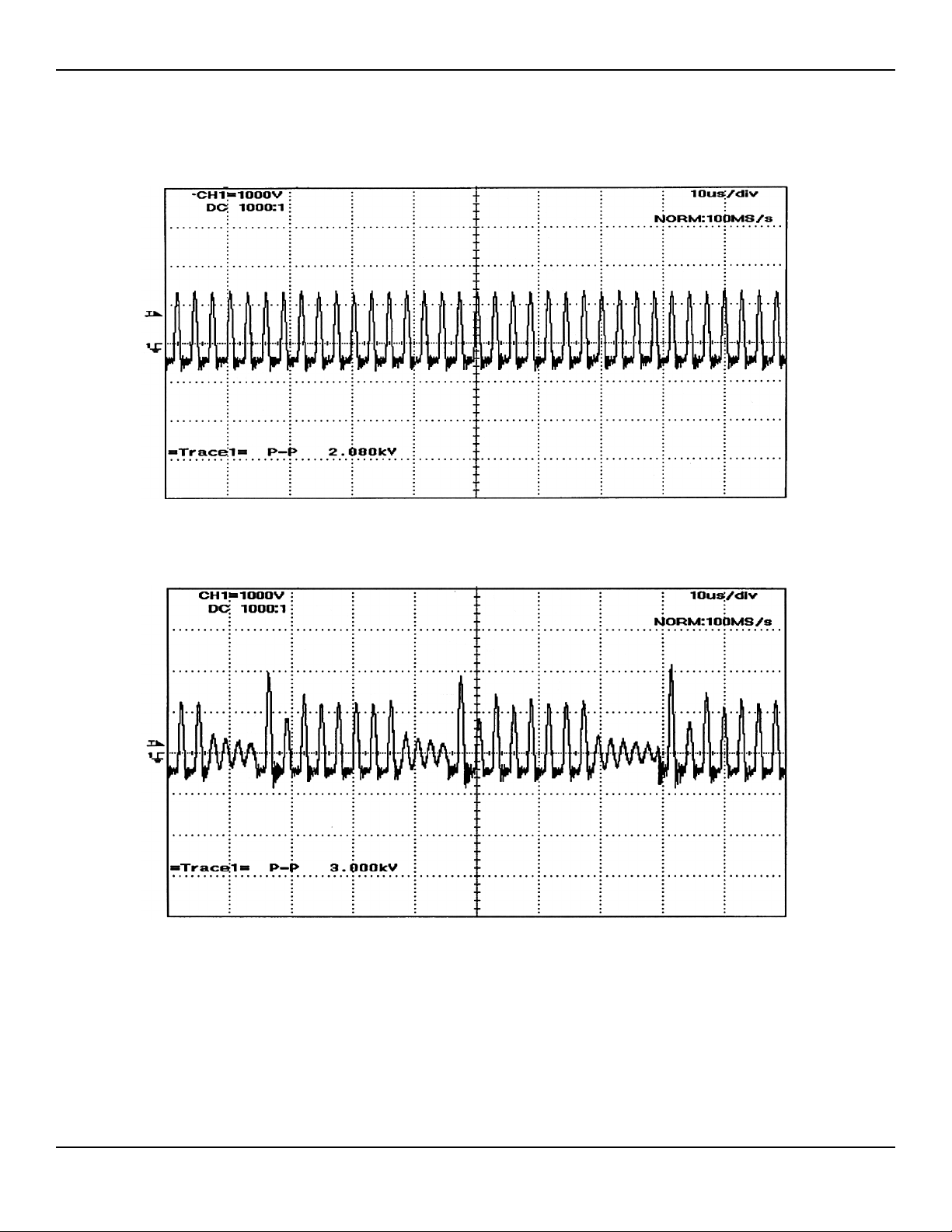
Reference Output Waveforms
The following figures are the output waveforms as viewed on an oscilloscope.
Figure 3-11 Cut mode waveform
Figure 3-12 Blend mode waveform
34 Bovie / Aaron Medical
Page 35
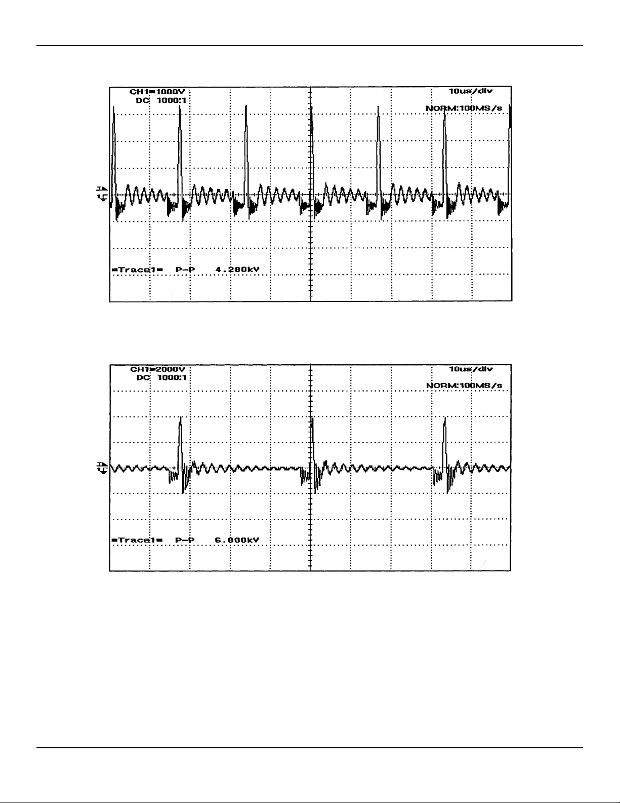
Figure 3-13 Coagulation mode waveform
Figure 3-14 Fulguration mode waveform
35Service Guide • Aaron 1250
Page 36
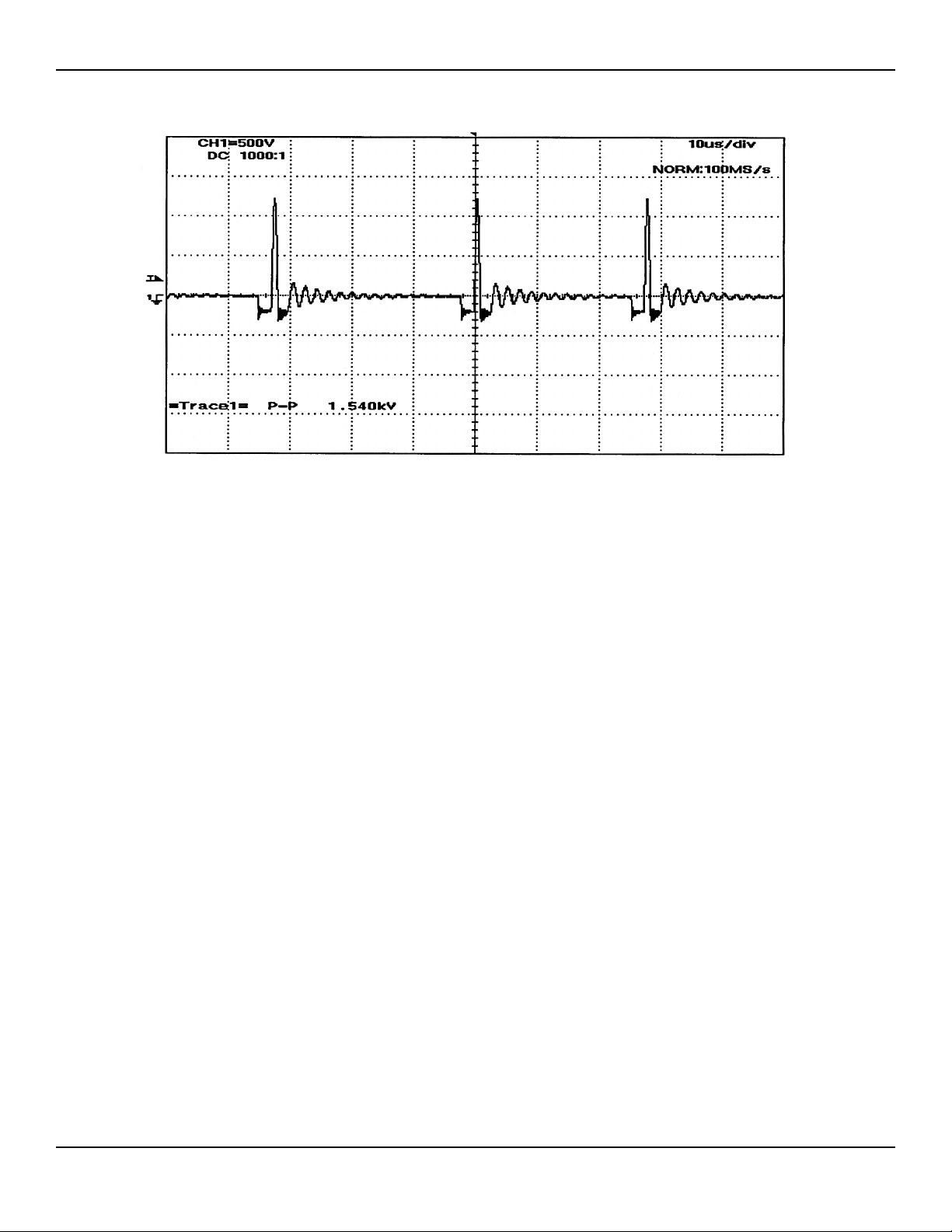
Figure 3-15 Bipolar mode waveform
36 Bovie / Aaron Medical
Page 37

THEORY OF OPERATION
This section includes the following information:
Block diagram
Functional overview of key circuits
System logic
Aaron 1250 control signal inputs and outputs.
37Service Guide • Aaron 1250
Page 38
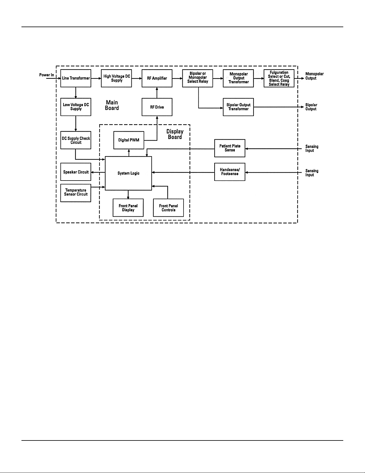
BLOCK DIAGRAM
Figure 4-1 Functional block diagram of the Aaron 1250 system
FUNCTIONAL OVERVIEW OF KEY CIRCUITS
The following descriptions highlight the main circuits in the Aaron 1250 Electrosurgical Generator.
High Voltage DC Supply
The unit incorporates a high voltage power supply to generate the RF output power. The high voltage power supply
delivers an unregulated DC output for the RF output. The nominal DC voltage from the high voltage power supply is
87 VDC ± 5V.
Low Voltage DC Supplies
The unit incorporates four regulated low voltage levels to control generator operations. They are: 15 VDC, 12 VDC,
8 VDC, and 5 VDC.
• The 15 VDC circuit supplies power for all of the request sense circuits, the switching of the mode relays and the
audio circuit.
• The 12 VDC circuit supplies power for the patient electrode sense module.
• The 8 VDC circuit supplies power for the RF drive circuit. This circuit turns on and off the power MOSFETS for
the RF output power.
• The 5 VDC circuit supplies power for the logic system, and all of the displays and indicators.
38 Bovie / Aaron Medical
Page 39

DC Supply Check Circuit
The DC Supply Check Circuit is used by system logic to monitor the high voltage DC supply. If the voltage
increases by 30%, the system displays error code E4 and disables the RF output.
For isolation purposes, the High Voltage Sense Voltage is measured from the 15-volt DC power supply.
Temperature Sensing Circuit
The temperature sensing circuit is used by the system logic to monitor the internal temperature of the unit. If the
temperature rises above 85° C, the system displays error code E7 and disables the RF output.
Four Request Activation Sensing Circuits
The Activation Request Sensing Circuit is used by the system logic to detect both hand controlled activation and footcontrolled activation requests. This circuit is made up of a Colpitts Oscillator (operating at approximately 50 kHz)
and a level detection circuit.
In a non-activation status, the Colpitts Oscillator operates at its set operating frequency, and presents a sine wave to
the level detection circuit. The level detection circuit converts the sine wave into a square wave. Activation will not
occur as long as a square wave is present.
When a resistance (approximately 200 W or less) is presented to the transformer’s secondary winding by a hand-control or foot-control, the sense transformer is essentially shorted. The "short" is felt on the transformer’s primary winding causing the Colpitts Oscillator to temporarily shut down.
When the oscillator shuts down, the sense signal becomes +5 VDC (logic "1"). This informs the system logic that a
handswitch or footswitch activation request has been made.
If the square wave (from any of the request sense circuits) is not present at the system logic when the unit is initially
turned on, an error code is displayed, an alarm sounds, and the RF output is disabled.
Speaker Circuit
The audio circuit is used by the system logic to generate activation tones and alarm tones. Volume for the activation
tones may be adjusted from the back panel of the unit.
NOTICE
Alarm volume cannot be adjusted up or down.
Patient Return Electrode Sensing Circuit
The Patient Return Electrode Sensing Module senses and sends signals to the system logic that displays which type of
patient return electrode is attached to the patient.
When you connect a single plate patient return electrode to the unit, the Pad Sensing Module will detect if the resistance is below 5 Ω. If it is, the Aaron 1250 will display the green single plate LED on the front of the unit.
When you connect a split plate patient return electrode to a patient, and the Pad Sensing Module detects a resistance
between 10 and 135 Ω, then the Aaron 1250 will display the green split plate LED on the front of the unit.
The Pad Sensing Module constantly monitors the patient contact quality. If the impedance changes by a specific
amount, then the unit will display an alarm, and immediately de-activate the RF output power.
WARNING
Patient Return Electrode contact quality is only monitored when a split plate patient return
electrode is attached to the patient.
39Service Guide • Aaron 1250
Page 40

RF Amplifier Circuit
The RF Amplifier Circuit generates the RF output energy that is delivered to the patient. It is a single-ended power
amplifier incorporating three power MOSFETs, and two step-up transformers.
The initial RF drive pulse is generated by the Digital PWM circuit and the system logic unit. When the RF drive
pulse turns the power MOSFETs "ON," current flows from the high voltage supply through one of the output
transformers, depending on which mode the unit is in, through the clamping diodes, and then through the
MOSFETs to high voltage ground.
The energy developed by the "ON" time is stored in an LC tank circuit. When the MOSFETs are OFF the energy is
delivered to the patient through the output capacitors. A longer "ON" time develops more energy in the LC tank circuit; therefore, more energy is delivered to the patient.
Monopolar Select Circuit
The monopolar select circuit is used to switch the Aaron 1250 between each of the four-monopolar modes. Selection
of the modes is accomplished through the matrix switches on the front panel. High voltage relays are used to switch
and isolate the four-monopolar configurations one from the other.
Monopolar / Bipolar Select Relays
The monopolar / bipolar select relays changes which output transformer is used to deliver the RF output to the
patient.
Controls and Indicators
The Aaron 1250 controls and indicators are listed below:
• MEMBRANE SWITCHES Toggle between modes.
• DISPLAYS Seven segment displays indicate the output power in watts.
• MODE INDICATORS Green LEDs indicate the present mode of the unit.
• POWER CONTROL KNOBS These mechanical encoders adjust the output power for each mode.
• POWER SWITCH A double pole single throw switch that snaps into the front bezel. This switch supplies the AC
mains current to the generator.
Digital PWM Circuit
The Digital Pulse Width Modulation (PWM) Circuit controls the output power of the unit. This digitally controlled
signal is used by the system logic to provide a precise signal to the RF drive.
The pulse width is determined by power setting (generated by the user) on the front of the unit.
When a power is selected, the system logic determines what the pulse width needs to be to deliver the requested
output.
SYSTEM LOGIC
The control logic uses a Field Programmable Gate Array as the “brain” of the Aaron 1250 Electrosurgical Generator.
This system interprets all of the inputs and delivers the correct corresponding outputs.
Every operation of the unit is controlled from this system.
A System Clock Circuit, composed of an oscillator, provides the basic operating frequency of 5 MHz.
The Reset Circuit provides a single pulse at the time the Aaron 1250 Electrosurgical Generator is turned on.
This pulse resets Field Programmable Gate Array to ensure proper operation.
40 Bovie / Aaron Medical
Page 41

AARON 1250 CONTROL SIGNAL INPUTS AND OUTPUTS
The following table lists the important input and output signals. From a troubleshooting standpoint, the absence
(and presence) of these signals will help you isolate problems.
Signal Name Description
PAD_SNS_ERROR This is the input signal from the Pad Sense Module that
informs the system logic that a pad sensing error has
occurred.
When a pad sense error occurs, a logic 1 (5 VDC) is sent
to the system logic section.
PAD_NSED This is an input signal from Pad Sense Module that
informs system logic that a single plate Patient Return
Electrode is attached to the front jack strip.
When the Pad Sense Module senses the presence of a
single plate patient return electrode, a logic 0 (0 VDC) is
sent to the system logic.
PAD_SED This is an input signal from Pad Sense Module that
informs the system logic that a split plate Patient Return
Electrode is attached to the patient.
When the Pad Sense Module senses the presence of a split
patient return electrode, a logic 0 (0 VDC) is sent to the
system logic.
AUD_DRV This is an output signal from the system logic that
generates the activation tones for all modes of operation.
A 1 kHz square wave is generated whenever cut or blend
mode is activated. A 2 kHz square wave is generated when
the coagulation, fulguration, or bipolar mode is activated.
This signal is used by the audio circuit.
ALM_DRV This is an output signal from the system logic that
generates a 2 kHz / 1 kHz square wave for activating the
alarm siren.
This signal is used by the audio circuit.
AUX_RLY_DRV This is an output signal from the system logic that controls
the accessory relay on the back panel.
41Service Guide • Aaron 1250
Page 42

Signal Name Description
TAP_SEL This is an output signal from the system logic that controls
relays on the main board. The relays select which
secondary windings will be used from the monopolar
output transformer.
OUT_SEL This is an output signal from the system logic that controls
relays on the main board. They control which output
transformer provides the RF output circuit delivered to
the patient.
HAND/FOOT_SEL This is an output signal from the system logic that controls
relays on the main board. These relays direct which output
jack receives the output RF power.
The output power for monopolar modes is switchable
from foot-controlled hand piece activation, to a handcontrolled (switching pencil) activation.
RF_DRV This is an output signal from the digital PWM circuit that
controls the pulse width duration for the RF drive.
CON_SENS This is an input signal that informs the system logic if the
24 pin ribbon cable (between the main board and the
display board) is connected.
When the cable is connected, a logic 0 (0 VDC) is sent to
system logic section. When the cable is damaged, not
secure, or not connected, a logic 1 (5 VDC) is sent to the
system logic.
TEMP_SEN This is an input signal from the Temperature Sense Circuit
that informs the system logic if the internal temperature of
the unit is above 85° C.
If the internal temperature of the unit is below 85° C a
logic 1 (5 VDC) is sent to the system logic.
If the internal temperature of the unit rises above 85° C a
logic 0 (0 VDC) is sent to the system logic.
HV_SENS This is an input signal from the high voltage sense circuit
that informs the system logic if a high voltage error
has occurred.
If the line voltage is within normal operating parameters a
logic 1 (5 VDC) is sent to the system logic.
If the line voltage increase by more than 30% a logic 0
(0 VDC) is sent to the system logic.
42 Bovie / Aaron Medical
Page 43

Signal Name Description
ACT_REQ_HAND_A This is an input signal from the Hand A request sense
circuit. Hand A refers to the Cut button on the handpiece. This signal is generated by a colpitts oscillator
located on the main board. When an activation request is
made, this oscillator become a logic 1 (5 VDC) signal.
ACT_REQ_HAND_B This is an input signal from the Hand B request sense
circuit. Hand B refers to the Coag button on the
handpiece. This signal is generated by a colpitts oscillator
located on the main board.
When an activation request is made, this oscillator
becomes a logic 1 (5 VDC) signal.
ACT_REQ_FOOT_A This is an input signal from the Foot A request sense
circuit. Foot A refers to the Cut pedal on the footswitch.
This signal is generated by a colpitts oscillator located on
the main board.
When an activation request is made, this oscillator
becomes a logic 1 (5 VDC) signal.
ACT_REQ_FOOT_B This is an input signal from the Foot B request sense
circuit. Foot B refers to the Coag pedal on the footswitch.
This signal is generated by a colpitts oscillator located on
the main board.
When an activation request is made, this oscillator
becomes a logic 1 (5 VDC) signal.
43Service Guide • Aaron 1250
Page 44

44 Bovie / Aaron Medical
Page 45

OPERATING THE AARON 1250
This section covers the following topics:
Inspecting the generator and accessories
Service personnel safety
Installation and placement
Functional (operational) checks
Operating the unit.
45Service Guide • Aaron 1250
Page 46

INSPECTING THE GENERATOR AND ACCESSORIES
Before each use of the Aaron 1250 Electrosurgical Generator, inspect the unit and all accessories to verify good
working order:
• Inspect for physical damage to the Electrosurgical Generator and its connections.
• Verify that the appropriate accessories and adapters are present.
• Inspect all cords and connectors for signs of wear, damage, and abrasion.
• Verify that no error messages are displayed when the unit is turned on.
SERVICE PERSONNEL SAFETY
WARNINGS
Hazardous Electrical Output This equipment is for operational use only by a trained, licensed,
physician. Bio-Med Technicians must also exercise caution when testing or repairing a unit.
Electric Shock Hazard Connect the generator power cord to a properly grounded receptacle. Do
not use power plug adapters.
Connect the power cord to a properly polarized and grounded power source with the frequency
and voltage characteristics that match those listed on the back of the unit.
Fire Hazard Do not use extension cords.
CAUTION
Do not stack equipment on top of the generator or place the generator on top of electrical
equipment. These configurations are unstable and / or do not allow for adequate cooling.
Provide as much distance as possible between the electrosurgical generator and other electronic
equipment (such as monitors). An activated electrosurgical generator may cause interference with
them.
Nonfunction of the generator may cause interruption of surgery. A backup electrosurgical
generator should be available for use.
Do not turn the activation tone down to an inaudible level. This activation tone alerts the surgical
team when an accessory (and the generator) is active.
When using a smoke evacuator in conjunction with the electrosurgical generator, place the smoke
evacuator a distance away from the generator. Set the generator’s volume control (on the rear
panel) at a level that ensures all activation tones may be heard.
NOTICE
If required by local codes, connect the generator to the hospital equalization connector with an
equipotential cable. There is a equipotential connector on the rear of the unit.
Connect the power cord to a wall outlet having the correct voltage. Otherwise product damage
may result.
46 Bovie / Aaron Medical
Page 47

INSTALLATION AND PLACEMENT
Place the Aaron 1250 Electrosurgical Generator on any flat surface with a tilt angle of not more than 10 degrees.
The unit relies on natural convection cooling. Do not block the rear vents.
Ensure that air flows freely on all sides of the unit.
WARNING
Connect the power cord to a properly polarized and grounded power source with the frequency
and voltage characteristics that match those listed on the back of the unit.
FUNCTIONAL (OPERATIONAL) CHECKS
Upon initial installation of the unit, perform the following checks. Refer to the figures in Controls and Indicators for
the location of connectors and generator controls.
WARNING
At no time should you touch the active electrode or bipolar forceps. A serious burn could result.
How to Set Up and Start the Aaron 1250 Unit
1. Verify that the Power Switch is in the OFF position and that no accessories are connected to the unit.
2. Connect a hospital-grade power cable to the AC power cable receptacle on the back of the unit, then to a
properly grounded wall outlet.
3. Connect a two-pedal footswitch to the matching footswitch receptacle on the back of the unit. Use only Aaron
footswitches. Although other types of footswitches may fit, they may not be compatible with this Electrosurgical
Generator.
4. Do not connect a Patient Return Electrode to the front of the unit at this time.
5. Turn the unit on by switching the power switch to the (ON) position.
6. The correct startup for the unit is a quick flash of all indicators and a series of beeps. The unit will return to the
last mode and power setting used.
How to Check the Patient Return Electrode Alarm Function
1. Adjust the power settings for each mode (Cut, Blend, Coagulation, Fulguration, and Bipolar) to one watt.
2. Press the Cut Pedal of the footswitch.
3. Verify that an alarm sounds for three seconds, and then the Patient Return Electrode Sensing Alarm Indicator
Light illuminates. This indicates NO patient return electrode connected to the unit.
4. Verify that adjusting the volume control on the back of the unit (while the alarm is sounding) cannot change the
alarm’s sound level.
47Service Guide • Aaron 1250
Page 48

How to Check the Bipolar Mode (with Footswitch)
1. Select the Bipolar mode by pressing the Bipolar Mode switch on the front panel.
Note: The unit automatically changes to Bipolar footswitching when you select the Bipolar mode.
2. Verify that the Bipolar Mode LED illuminates green, and that the system generates the Coag tone when you press
the Coag pedal (Blue) on the footswitch.
3. While activating the Bipolar mode, rotate the volume control over the full range to verify that the sound is audible
throughout the range.
4. Confirm that releasing the Coag pedal returns the unit to an idle state.
How to Check the Monopolar Mode (with Footswitch)
1. Select monopolar foot control by pressing the Footswitch Control Selector until the Monopolar Footswitch
Control Indicator illuminates.
2. Connect a single-plate patient return electrode to the Return Electrode receptacle of the unit. Verify that the green
single-plate patient return electrode indicator illuminates.
3. Press the Cut pedal on the footswitch. Verify that the Cut and Blend Activation Indicator illuminates and that the
system generates the Cut activation tone.
4. While activating the Cut mode, rotate the volume control over the full range to verify that the sound is audible
throughout the range.
5. Press the Coag pedal on the footswitch. Verify that the Coagulation, Fulguration, and Bipolar Activation Indicator
illuminates and that the system generates the Coagulation activation tone.
6. While activating the Coag mode, rotate the volume control over the full range to verify that the sound is audible
throughout the range.
How to Check the Monopolar Mode (with Handswitch)
1. Connect a handswitching handpiece to the Monopolar Handswitching receptacle.
2. Activate, one at a time, the Cut and Coag handswitching controls. Verify that each control causes the correct
indicator and tone to sound.
48 Bovie / Aaron Medical
Page 49

OPERATING THE UNIT
Monopolar Cut Select the desired mode of operation (Pure Cut or Blend), then select the power settings by rotating
the Cut and Blend Power Control Dial.
Monopolar Coag Select the coag mode of operation (Coagulation or Fulguration), then select the power setting by
rotating the Coag and Bipolar Power Control Dial.
Bipolar Select the mode of operation for Bipolar (coagulation or fulguration), then select the Bipolar power settings
by rotating the Coag and Bipolar Power Control Dial.
Activate the generator by pressing the appropriate button on the handswitch or footswitch.
NOTICE
One footswitch can activate either monopolar or bipolar operation.
49Service Guide • Aaron 1250
To Activate… Press This… On This Device…
Monopolar
Cut or Blend Modes Yellow Button Handswitching Pencil
Yellow Pedal Footswitch
Coagulation or Fulguration Modes Blue Button Handswitching Pencil
Blue Pedal Footswitch
Bipolar
Any Bipolar Yellow (Cut) or Blue (Coag) Pedal Footswitch
Page 50

50 Bovie / Aaron Medical
Page 51

MAINTENANCE
This section includes the following information:
Cleaning the unit
Performing periodic inspection
Replacing fuses.
51Service Guide • Aaron 1250
Page 52
CLEANING THE UNIT
After each use, clean the unit.
WARNING
Electric Shock Hazard Always turn off and unplug the generator before cleaning.
NOTICE
Do not clean the generator with abrasive cleaning or disinfectant compounds, solvents, or other
materials that could scratch the panels or damage the generator.
1. Turn off the generator, and unplug the power cord from the wall outlet.
2. Thoroughly wipe all surfaces of the generator and power cord with a mild cleaning solution or disinfectant and a
damp cloth. Follow the procedures approved by your institution or use a validated infection control procedure.
Do not allow fluids to enter the chassis. Do not sterilize the generator.
PERFORMING PERIODIC INSPECTION
Every six months, visually inspect the Aaron 1250 for signs of wear or damage. In particular, look for any of the
following problems:
• Damage to the power cord
• Damage to the power cable receptacle
• Obvious damage to the unit
• Damage to any receptacle
• Accumulation of lint or debris in or around the unit.
REPLACING FUSES
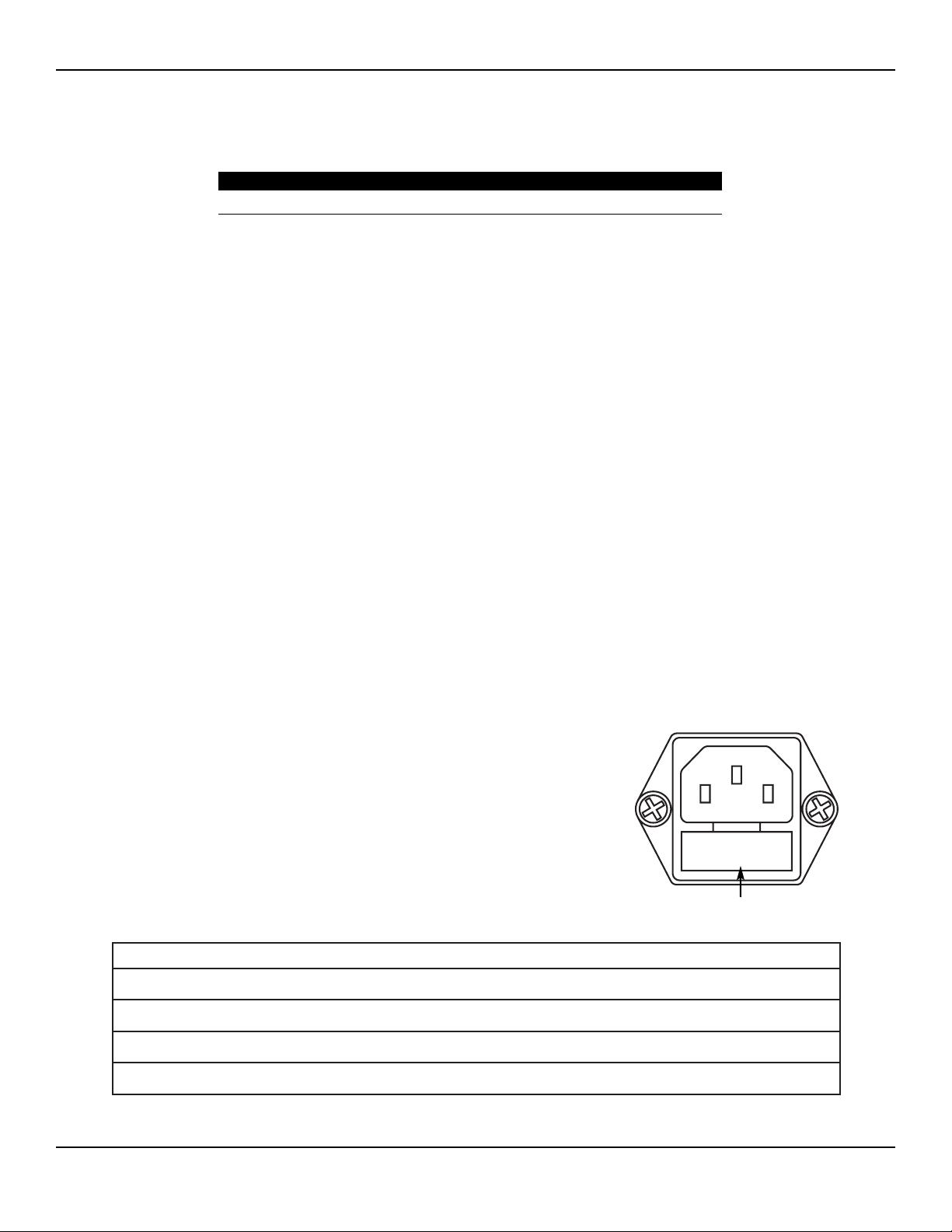
Fuses for the unit reside directly below the Power Cable Receptacle on the rear of the unit.
To replace the fuses, follow this procedure:
1. Unplug the power cord from the wall outlet.
2. Remove the power cord from the Power Cable Receptacle on the rear panel.
3. To release the fuse drawer, insert a small flathead screwdriver into the slot on
the drawer below the power cord receptacle. Then, slide the drawer out.
4. Remove the two fuses and replace them with new fuses with the same values.
5. Insert the fuse holder into the Power Cable Receptacle.
Use the following fuses:
52 Bovie / Aaron Medical
110 - 120 V 220 - 240 V
VAC 250 250
AMPS 5.0 A 3.15 A
Type Slow Blow Slow Blow
Size 5 x 20 mm 5 x 20 mm
Fuse Holder
Page 53

TROUBLESHOOTING
This section includes error code descriptions and actions to take to resolve them.
53Service Guide • Aaron 1250
Page 54

RECOMMENDED EQUIPMENT FOR TROUBLESHOOTING
The following equipment enables you to troubleshoot and repair the Aaron 1250 Electrosurgical Generator.
• Digital multimeter with leads
• Electrosurgical analyzer or a true RMS voltmeter such as a Fluke 8920A
• Wideband current transformer such as a Pearson 4100
• Noninductive RF load resistors 200 W, 500 W, 800 W, 1000 W
• Oscilloscope (dual channel) at 100 MHz
• Oscilloscope probes, (2) 10X and 1000X
• Bovie/Aaron footswitch
• Bovie/Aaron handswitching pencil (single use or reusable)
• Standard technician’s tool kit
• Miscellaneous test leads and cables.
TROUBLESHOOTING THE AARON 1250
If the generator is not functioning properly, use the information in this section to perform the following activities:
• Identify and correct the malfunction.
• If an error code was displayed, take the appropriate action(s) to correct the error condition.
Inspecting the Generator
If the Aaron 1250 malfunctions, check for obvious conditions that may have caused the problem.
1. Check the generator for visible signs of physical damage.
2. Verify that all accessory cords are properly connected.
3. Check the power cord. Replace the power cord if you find exposed wires, cracks, frayed insulation, or a
damaged connector.
4. Open the fuse drawer and inspect the fuse housing and fuses for damage and corrosion.
5. Verify that the fuses are firmly seated. An internal component malfunction in the generator can damage the fuses.
6. You may need to replace the fuses if the generator fails the self-test or stops functioning. Refer to Fuse
Replacement in Section 6.
Inspecting the Receptacles
Equipment required:
• Footswitch
• Bipolar cable
• Monopolar instruments (handswitch and footswitch)
• Return electrode cable.
Procedure:
1. Turn off the generator.
2. Disconnect the power cord from the wall receptacle.
3. Check the footswitch receptacle on the rear of the unit for obvious signs of obstruction and damage.
4. Check for a secure fit by inserting the footswitch connector into footswitch receptacle.
If the footswitch receptacle is damaged, replace the footswitch connector assembly.
54 Bovie / Aaron Medical
Page 55

5. Check the Bipolar receptacle on the front of the unit for obstruction or damage.
6. Insert a bipolar cable into the bipolar receptacle on the front of the unit. Verify a secure fit.
If the Bipolar receptacle is damaged, replace the bipolar connector assembly.
7. Check the monopolar handpiece receptacle on the front of the unit for obstruction or damage.
8. Insert a handswitching pencil into the monopolar handpiece receptacle on the front of the unit. Verify a
secure fit.
If the monopolar handpiece receptacle is damaged, replace the monopolar handpiece assembly.
9. Check the monopolar foot controlled receptacle on the front of the unit for obstruction or damage.
10. Insert a monopolar foot controlled handpiece into the monopolar foot control receptacle on the front of the
unit. Verify a secure fit.
If the monopolar foot controlled receptacle is damaged, replace the connector assembly.
11. Check the Patient Return Electrode receptacle on the front of the unit for a broken pin or an obstruction.
12. Insert a return electrode cable into the return electrode receptacle. Verify a secure fit.
If the return electrode receptacle on the front of the unit is damaged, replace the return electrode cable assembly.
Inspecting Internal Components
CAUTION
The generator contains electrostatic-sensitive (ESS) components. When repairing the generator,
work at a static-control workstation.
Wear a grounding strap when handling electrostatic-sensitive components.
Handle circuit boards by their nonconductive edges.
Use an anti-static container for transport of electrostatic-sensitive components and circuit boards.
To inspect the internal components, follow this procedure:
1. Remove the four screws that secure the cover to the chassis.
2. Lift the cover off the chassis. Save the cover and screws for later reinstallation.
3. Visually inspect and verify that all connectors are firmly seated.
4. Inspect each board for damaged components, wires, cracks and corrosion.
5. Reinstall the cover by positioning the cover over the chassis, and securing the four screws.
55Service Guide • Aaron 1250
Page 56

UNDERSTANDING ERROR CODES AND AUDIO TONES
The Aaron 1250 Electrosurgical Generator includes automatic, perpetual, self-diagnostics. If the diagnostics detect an
error, the system displays an error code, sounds an audible tone, and deactivates the output power.
Any errors detected will shut down the RF output power.
NOTICE
Internal firmware self-diagnostics continually monitor the unit’s operation to ensure proper and
safe performance.
Most error codes result from faults in accessories attached to the unit. The following table lists the error codes,
describes the error, and recommends actions to take to resolve the error.
56 Bovie / Aaron Medical
ERROR CODE DESCRIPTION RECOMMENDED ACTION
F1
(on the Cut /
Blend display)
F1
(on the
Coagulation /
Fulguration /
Bipolar display)
Handswitch or monopolar
footswitch cut pedal may be stuck
Handswitch or monopolar
footswitch coag pedal may
be stuck
1.
2.
3.
4.
Turn off, then turn on the generator. Do not press buttons or
accessory activation devices during the self-test.
If the alarm number reappears, disconnect all accessories.
Turn off, then turn on the generator again.
If the problem persists, replace the handpiece or footswitch
and repeat the restart.
If the alarm number reappears, record the number and call
the Aaron Medical Service Center.
F2
Cut and Coag buttons activated
simultaneously
(pencil or footswitch)
The unit does not allow simultaneous activation of the
cut and coagulation modes. Release either the cut or
coag button on the handpiece, or the cut or coag pedal
on the footswitch.
F3
Footswitch Cut or Coag Pedal
pressed while in Bipolar Foot
Control and the unit is not in
Bipolar Mode
The unit will not allow the Footswitch to activate the unit
if Bipolar Footcontrol is selected, but the Bipolar Mode
is not selected.
E4
Line voltage error
(Line voltage too high)
1.2.Turn the unit off.
Verify that the unit is connected to the correct line voltage.
E7
Internal temperature of the unit
exceeded limit
1.2.Turn unit off.
Allow unit to cool for 20 minutes.
Page 57

CORRECTING COMMON PROBLEMS
If a solution is not readily apparent, use the table below to help identify and correct specific malfunctions. After you
correct the malfunction, verify that the generator successfully completes the self-test.
57Service Guide • Aaron 1250
Situation Possible cause Recommended action
Generator does not respond when
turned on
Disconnected power cord, faulty wall
receptacle, or faulty power cord
1.2.Check power cord connections (generator
and wall receptacle).
Connect the power cord to a functional wall
receptacle. If necessary, replace the power
cord.
Fuse drawer is open or fuses blown 1.2.Close the fuse drawer. If necessary, replace
the fuse(s).
If a problem persists, use a backup
generator.
Loose or disconnected internal cables Check all internal connections.
Faulty power entry module or
connections
Check the power entry module and its cable
connections.
Faulty power switch Replace the power switch.
Generator is on, but did not complete
the self-test.
An alarm condition exists. Check the display for an error code. Note
the number and refer to Error Code list.
Loose or disconnected internal cables Check and correct all internal connections.
Faulty power switch Replace the power switch.
Main board malfunction Replace the main board.
Display board malfunction Replace the display board.
Activation and / or alarm tones do
not sound; speaker is malfunctioning.
Loose or damaged connection between
speaker board and main board
Check / connect all connections from the
speaker board to the main board.
Loose or disconnected cable between
main board and display board
Check / connect ribbon cable from the main
board to the display board.
Main board malfunction Replace the main board.
Display board malfunction Replace the display board.
Page 58

58 Bovie / Aaron Medical
Situation Possible cause Recommended action
Blank or confusing LED display Faulty ribbon cable between Main
board and Display board
Check / connect ribbon cable that connects
the display board to the main board.
Display board malfunction Replace the display board.
Mode buttons do not operate
correctly when pressed
Loose or disconnected cable between
main board and display board
Check / connect ribbon cable from the main
board to the display board
Loose or disconnected cable between
front panel overlay and display board
Check / connect cable from front panel
overlay to the display board
Damaged front panel overlay Replace front panel overlay
Generator is on and the accessory
is activated, but generator does not
deliver output.
Malfunctioning footswitch or
handswitching instrument
1.
2.
3.
Turn off the generator. Check and correct
all accessory connections.
Turn on the generator.
Replace the accessory if it continues to
malfunction.
Display board malfunction Replace the display board.
Power set too low Increase the power setting.
An error condition exists 1.2.Check the Cut and Coag displays for an
error code number.
Note the number and refer to the error codes
descriptions in this section.
Main board malfunction Replace the main board.
RF output stage malfunction 1.
2.
3.
Troubleshoot the RF output stage as
described below:
On the main board, verify output pulses
(TP1) during activation.
If pulses are not present replace the Main
board. Check the power MOSFETs for failure
(typically fail as shorted). Check all output
relays to verify that they are toggling during
operation. If they are not, check the relay
drivers.
Footswitch will not activate output. Malfunctioning or damaged footswitch
receptacle
Replace the Footswitch connector assembly.
Footswitch activation signal lost on
main board
Replace the main board.
Page 59

59Service Guide • Aaron 1250
Situation Possible cause Recommended action
Continuous monitor interference Faulty chassis-to-ground connections 1.2.Check and correct the chassis ground
connections for the monitor and, if applicable,
for the generator.
Check other electrical equipment in the room
for defective grounds.
Electrical equipment is grounded to
different objects rather than a common
ground.
The generator may respond to the
resulting voltage differences between
grounded objects.
Plug all electrical equipment into line power
at the same location.
Malfunctioning monitor Replace the monitor.
Interference with other devices only
when generator is activated
Metal-to-metal sparking Check all connections to the generator,
patient return electrode, and accessories.
High settings used for fulguration Use lower power settings for fulguration or
select the Coagulation mode.
Electrically inconsistent ground wires
in the operating room
Verify that all ground wires are as short as
possible and go to the same grounded metal.
If interference continues when the
generator is activated, the monitor is
responding to radiated frequencies.
Check with the manufacturer of the monitor.
Some manufacturers offer RF choke filters
for use in monitor leads.
The filters reduce interference when the
generator is activated and minimize the
potential for an electrosurgical burn at the
site of the monitor electrode.
Page 60

60 Bovie / Aaron Medical
Situation Possible cause Recommended action
Pacemaker interference Intermittent connections or metal-to-
metal sparking
1.2.Check all connections to the generator.
It may be necessary to re-program the
pacemaker.
Current traveling from active to return
electrode during monopolar
Electrosurgery is passing too close to
pacemaker.
1.
2.
3.
4.
5.
Use bipolar instruments, if possible. If you
must use a monopolar instrument, place the
patient return electrode as close as possible
to the surgical site.
Make sure the current path from the surgical
site to the patient return electrode does not
pass through the vicinity of the heart or the
site where the pacemaker is implanted.
Always monitor patients with pacemakers
during surgery and keep a defibrillator
available.
Consult the pacemaker manufacturer or
hospital.
Contact the Cardiology Department for
further information when use of
electrosurgical appliances is planned on
patients with cardiac pacemakers.
Abnormal neuromuscular stimulation
(stop surgery immediately)
Metal-to-metal sparking Check all connections to the generator,
patient return electrode, and active
electrodes.
Can occur during coag Use a lower power setting for the Fulgurate
mode or select the Coagulation mode.
Abnormal 50 Hz - 60 Hz leakage
currents
Inside the generator, carefully inspect for
damage that may cause shorting between
the AC line voltage and connected patient
components.
Page 61

MAIN BOARD TEST POINTS
DISPLAY BOARD TEST POINTS
61Service Guide • Aaron 1250
Test Point Description
TP1 (RFDRIVE) RF DRIVE SIGNAL
TP2 (+HV) HIGH VOLTAGE POWER SUPPLY
TP3 (HVGND) HIGH VOLTAGE GROUND
TP4 (+15 VDC) 15 VOLT DC POWER SUPPLY
TP5 (+12 VDC) 12 VOLT DC POWER SUPPLY
TP6 (+8 VDC) 8 VOLT DC POWER SUPPLY
TP7 (LVGND) LOW VOLTAGE GROUND
TP8 (+5 VDC) 5 VOLT DC POWER SUPPLY
Test Point Description
TP1 DIGITAL GROUND
TP2 NOT USED
TP3 NOT USED
Page 62

62 Bovie / Aaron Medical
Page 63

REPAIR POLICY AND PROCEDURES
Refer to this section for information on
Responsibility of the manufacturer
Returning the generator for service
63Service Guide • Aaron 1250
Page 64

RESPONSIBILITY OF THE MANUFACTURER
Bovie Aaron Medical is responsible for the safety, reliability, and performance of the generator only under the
following circumstances:
• The user has followed the Installation and Setup Procedures in this Service Guide.
• Persons authorized by Bovie Aaron Medical performed assembly operation, readjustments, modifications,
or repairs.
• The electrical installation of the relevant room complies with local codes and regulatory requirements, such as
IEC and BSI.
• Equipment use is in accordance with the Bovie Aaron Medical instructions for use.
For warranty information, refer to APPENDIX A - WARRANTY.
RETURNING THE GENERATOR FOR SERVICE
Before you return the generator, call your Bovie Aaron Medical representative for assistance. If instructed to send the
generator to Bovie Aaron Medical, first obtain a Returned Goods Authorization Number. Then clean the Generator
and ship it to Bovie Aaron Medical for service.
Step 1 – Obtain a Returned Goods Authorization Number
Call the Bovie Aaron Medical Customer Service Center to obtain a Returned Goods Authorization Number.
Have the following information ready when you call:
• Hospital / clinic name / customer number
• Telephone number
• Department / address, city, state, and zip code
• Model number
• Serial number
• Description of the problem
• Type of repair to be done
Step 2 – Clean the Generator
WARNING
Electric Shock Hazard
- Always turn off and unplug the generator before cleaning.
NOTICE
Do not clean the generator with abrasive cleaning or disinfectant compounds, solvents, or other
materials that could scratch the panels or damage the generator.
A. Turn off the generator, and unplug the power cord from the wall outlet.
B. Thoroughly wipe all surfaces of the generator and power cord with a mild cleaning solution or disinfectant and
a damp cloth. Follow the procedures approved by your institution or use a validated infection control procedure.
Do not allow fluids to enter the chassis. You cannot sterilize the generator.
Step 3 – Ship the Generator
A. Attach a tag to the generator that includes the Returned Goods Authorization Number and the information
(hospital, phone number, etc.) listed in Step 1 – Obtain a Returned Goods Authorization Number.
B. Be sure the generator is completely dry before you pack it for shipment. Package it in its original shipping
container, if available.
C. Ship the generator, prepaid, to the address given to you by the Bovie Aaron Medical Service Center.
64 Bovie / Aaron Medical
Page 65

WARRANTY
Bovie Aaron Medical warrants each product manufactured by it to be free from defects in material and workmanship
under normal use and service for the period(s) set forth below.
Aaron Medical’s obligation under this warranty is limited to the repair or replacement, at its sole option, of any
product, or part thereof, which has been returned to it or its Distributor within the applicable time period shown
below after delivery of the product to the original purchaser, and which examination discloses, to Aaron Medical’s
satisfaction, that the product is indeed, defective.
This warranty does not apply to any product, or part thereof, which has been repaired or altered outside Aaron
Medical’s factory in a way so as, in Aaron Medical’s judgment, to affect its stability or reliability, or which has been
subjected to misuse, neglect, or accident.
The warranty periods for Aaron Medical products are as follows:
• Electrosurgical Generators: Two years from date of shipment
• Mounting Fixtures (all models): Two years from date of shipment
• Footswitches (all models): Ninety days from date of shipment
• Patient Return Electrodes: Shelf life only as stated on packaging
• Sterile Single Use Accessories: Only as stated on packaging
65Service Guide • Aaron 1250
Page 66

This warranty is in lieu of all other warranties, express or implied, including without limitation, the warranties of
merchantability and fitness for a particular purpose, and of all other obligations or liabilities on the part of Aaron
Medical.
Aaron Medical neither assumes nor authorizes any other person to assume for it any other liability in connection
with the sale or use of any of Aaron Medical’s products.
Notwithstanding any other provision herein or in any other document or communication, Aaron Medical’s liability
with respect to this agreement and products sold hereunder shall be limited to the aggregate purchase price for the
goods sold by Aaron Medical to the customer.
There are no warranties which extend beyond the terms hereof.
Aaron Medical disclaims any liability hereunder or elsewhere in connection with the sale of this product, for indirect
or consequential damages.
This warranty and the rights and obligations hereunder shall be construed under and governed by the laws of the
State of Florida, USA.
The sole forum for resolving disputes arising under or relating in any way to this warranty is the District Court of the
County of Pinellas, State of Florida, USA.
Aaron Medical, its dealers, and representatives reserve the right to make changes in equipment built and/or sold by
them at any time without incurring any obligation to make the same or similar changes on equipment previously
built and/or sold by them.
66 Bovie / Aaron Medical
Page 67

BOARD DRAWINGS AND SCHEMATICS
This supplement contains the assembly drawings and schematics for the following printed circuit boards:
Control board
Display board
Footswitch board
Power Supply/RF board.
67Service Guide • Aaron 1250
Page 68

HOW TO ORDER PARTS FROM AARON MEDICAL
Once you have determined what parts you need from the drawings and Bill of Materials, call our Technical Service
Department.
Our trained staff will verify the part numbers and arrange immediate delivery. The Technical Service Department can
relay cost information, determine parts availability, and suggest any assembly updates available.
AARON 1250 DESIGN BREAKDOWN & DRAWING REFERENCE
AARON DRAWING & SCHEMATIC PACKAGE
Following tri-folds
68 Bovie / Aaron Medical
PCB BOARD ASSEMBLIES
P/N Description
20-037-001 Main PCB Assembly
20-033-001 Display PCB Assembly
20-045-001 Speaker PCB Assembly
20-009-001 Relay PCB Assembly
ENCLOSURE
P/N Description
10-040-001 Back Panel, White
10-041-001 Bottom Panel, White
10-042-001 Top Panel, White
06-053-001 Front Panel, White
CONNECTORS
P/N Description
21-073-001 Bipolar Receptacle Assembly
21-074-001 Mopolar Receptacle Assembly
21-075-001 Monopolar Foot-Control Receptacle Assembly
21-076-001 Return Electrode Receptacle Assembly
21-090-001 Footswitch Receptacle Assembly
21-086-001 Accessory Relay Receptacle Assembly
FUSES
P/N Description
02-033-500 Fuse 250 VAC 5.0 Amp, Slow Blow 5x20 mm
(F1 & F2 and Power Entry Module for 120 VAC Model Only)
02-033-001 Fuse 250 VAC 3.15 Amp, Slow Blow 5x20 mm
(F1 & F2 and Power Entry Module for 220 VAC Model Only)
MISCELLANEOUS
P/N Description
19-034-001 Line Transformer
05-023-001 Power Entry Module and Filter
15-079-001 Front Panel Overlay with Membrane Switches
07-044-001 Switch DPST Snap Mount On/Off
21-078-001 24 Pin Ribbon Cable
 Loading...