

BOURNS SDR2207 Service Manual

SDR2207 Series - SMD Power Inductors
Features
■ Available in E12 series
■ Low height of only 7.0 mm
■ Inductance as low as 0.8 µH
■ High current up to 16 amps
■ Lead free version available (see How to
Order)
■ Lead free versions are RoHS compliant*
Applications
■ Input/output of DC/DC converters
■ Power supplies for:
• Portable communications equipment
• Camcorders
• LCD TVs
• Car radios
Electrical Specifications
Product Dimensions
Recommended Layout
General Specifications
Test Voltage.....................................0.1 V
Reflow Soldering....230 °C; 10 sec. max.
Operating Temperature..-40 °C to +125 °C
(Temperature rise included)
Storage Temperature
.................................-40 °C to +125 °C
Resistance to Soldering Heat
................................230 °C for 10 sec.
Materials
Core.........................................Ferrite DR
Wire .............................Enameled copper
Terminal Electrode ......See How to Order
Base................................Phenolic T375J
Adhesive ..............................Epoxy resin
Rated Current
....................Ind. drop 10 % typ. at Isat
Temperature Rise
.......................40 °C max. at rated Irms
Packaging ....................250 pcs. per reel
22.0 ± 0.3
(.866 ± .012)
= START OF WINDING
7.0 + 0.8/-0.4
(.276 + .031/-.016)
15.0 ± 0.3
(.591 ± .012)
4.0
(.157)
13.5
(.531)
9.0
(.354)
Electrical Schematic
Inductance 100 KHz
Q
Test SRF
RDC
I rms I sat
Bourns Part No.
(
µµ
H) Tol. %
Ref.
Frequency Min.
(mΩΩ)
Max. Typ.
(MHz) (MHz) (A) (A)
SDR2207-R80M_ 0.8 ± 20 30 5 102.0 2.8 16.0 35.0
SDR2207-1R2M_ 1.2 ± 20 30 3 70.0 3.8 15.0 30.0
SDR2207-1R8M_ 1.8 ± 20 31 3 51.0 4.5 13.0 25.0
SDR2207-2R7M_ 2.7 ± 20 38 3 51.0 7.0 10.0 20.0
SDR2207-3R3M_ 3.3 ± 20 38 3 39.0 7.8 9.0 17.0
SDR2207-4R7M_ 4.7 ± 20 38 3 33.0 8.8 8.5 15.0
SDR2207-5R6M_ 5.6 ± 20 50 3 30.0 13.4 7.8 14.0
SDR2207-6R8M_ 6.8 ± 20 38 3 27.0 14.2 7.5 12.0
SDR2207-8R2M_ 8.2 ± 20 35 3 25.0 15.5 7.0 11.0
SDR2207-100M_ 10 ± 20 53 5 20.0 17.2 6.5 10.0
SDR2207-120Y_ 12 ± 15 50 5 19.0 23.6 5.5 9.5
SDR2207-150Y_ 15 ± 15 38 5 16.0 28.8 5.0 9.0
SDR2207-180Y_ 18 ± 15 46 5 15.0 33.0 4.6 8.0
SDR2207-220Y_ 22 ± 15 27 3 14.0 39.4 4.0 6.5
SDR2207-270Y_ 27 ± 15 22 3 12.0 43.5 3.8 6.0
SDR2207-330Y_ 33 ± 15 27 3 11.0 58.4 3.4 5.5
SDR2207-390K_ 39 ± 10 18 3 10.0 65.0 3.2 5.2
SDR2207-470K_ 47 ± 10 27 3 9.0 91.2 2.8 5.0
SDR2207-560K_ 56 ± 10 25 2 8.3 96.5 2.6 4.5
SDR2207-680K_ 68 ± 10 18 2 7.9 112.0 2.4 4.0
SDR2207-820K_ 82 ± 10 28 2 6.5 144.0 2.3 3.5
SDR2207-101K_ 100 ± 10 18 2 6.2 168.0 2.2 3.0
SDR2207-121K_ 120 ± 10 20 2 6.0 230.0 1.6 3.0
SDR2207-151K_ 150 ± 10 22 2 5.8 250.0 1.5 2.6
SDR2207-181K_ 180 ± 10 20 2 5.7 300.0 1.3 2.5
SDR2207-221K_ 220 ± 10 19 2 5.5 380.0 1.2 2.4
SDR2207-271K_ 270 ± 10 17 2 5.3 470.0 1.1 2.2
SDR2207-331K_ 330 ± 10 20 1 5.1 560.0 1.0 1.9
SDR2207-391K_ 390 ± 10 17 1 4.9 680.0 0.9 1.7
SDR2207-471K_ 470 ± 10 19 1 4.7 850.0 0.8 1.4
SDR2207-561K_ 560 ± 10 18 1 4.5 1000 0.8 1.3
SDR2207-681K_ 680 ± 10 16 1 4.2 1100 0.7 1.2
SDR2207-821K_ 820 ± 10 16 1 3.9 1400 0.6 1.1
SDR2207-102K_ 1000 ± 10 15 1 3.5 1800 0.6 1.0
DIMENSIONS:
MM
(INCHES)
LEAD FREE
VERSIONS ARE
RoHS COMPLIANT
*RoHS Directive 2002/95/EC Jan 27 2003 including Annex
Specifications are subject to change without notice.
Customers should verify actual device performance in their specific applications.
How to Order
SDR2207 - 100M __
Model
Value/Tolerance: from table
Termination
L = Cu/Sn
Blank = Cu/SnPb
查询SDR2207供应商
34.0
(1.34)
38.4
(1.51)
2.0 ± 0.5
(.079 ± .020)
50.0
(1.969)
330
(12.99)
DIA.
13.0 ± 0.5
(.512 ± .020)
DIA.
13.0 ± 0.5
(.512 ± .020)
DIA.
21.0 ± 0.8
(.827 ± .031)
EMBOSSED
CARRIER
EMBOSSED
CAVITY
0.10
(.004)
THICKNESS
MAX.
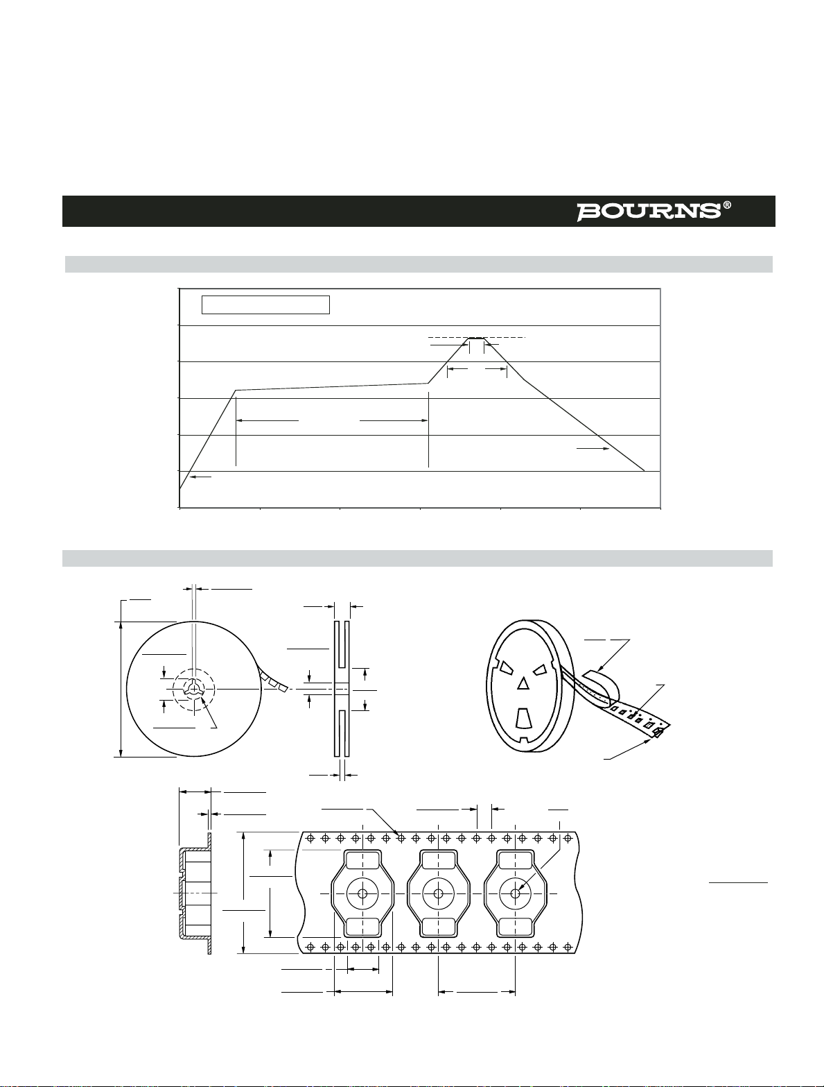
Packaging Specifications
22.4 ± 0.1
(.882 ± .004)
32.0 ± 0.3
(1.26 ± .012)
9.0 ± 0.1
(.354 ± .004)
15.5 ± 0.1
(.610 ± .004)
20.0 ± 0.1
(.787 ± .004)
4.0 ± 0.1
(.157 ± .004)
1.55 ± 0.05
(.061 ± .002)
2.0
(.079)
MIN.
8.45 ± 0.1
(.333 ± .004)
0.5 ± 0.05
(.020 ± .002)
QTY: 250 PCS. PER REEL
SDR2207 Series - SMD Power Inductors
DIMENSIONS:
MM
(INCHES)
REV. 02/05
Specifications are subject to change without notice.
Customers should verify actual device performance in their specific applications.
Soldering Profile
0
50
100
150
200
250
300
0 50 100 150 200 250 300
Temperature (°C)
Ramp-up
4 °/second maximum
Ramp-down
5 °C/second maximum
<1> Max. of 30 seconds > 200 °C
<2> Max. of 10 seconds at 230 °C
120 - 150 seconds
<1>
Time (seconds)
230 °C
<2>
 Loading...