

BOURNS 7914 Service Manual
*RoHS Directive 2002/95/EC Jan 27 2003 including Annex.
†“Fluorinert” is a registered trademark of 3M Co.
Specifications are subject to change without notice.
Customers should verify actual device performance in their specific applications.
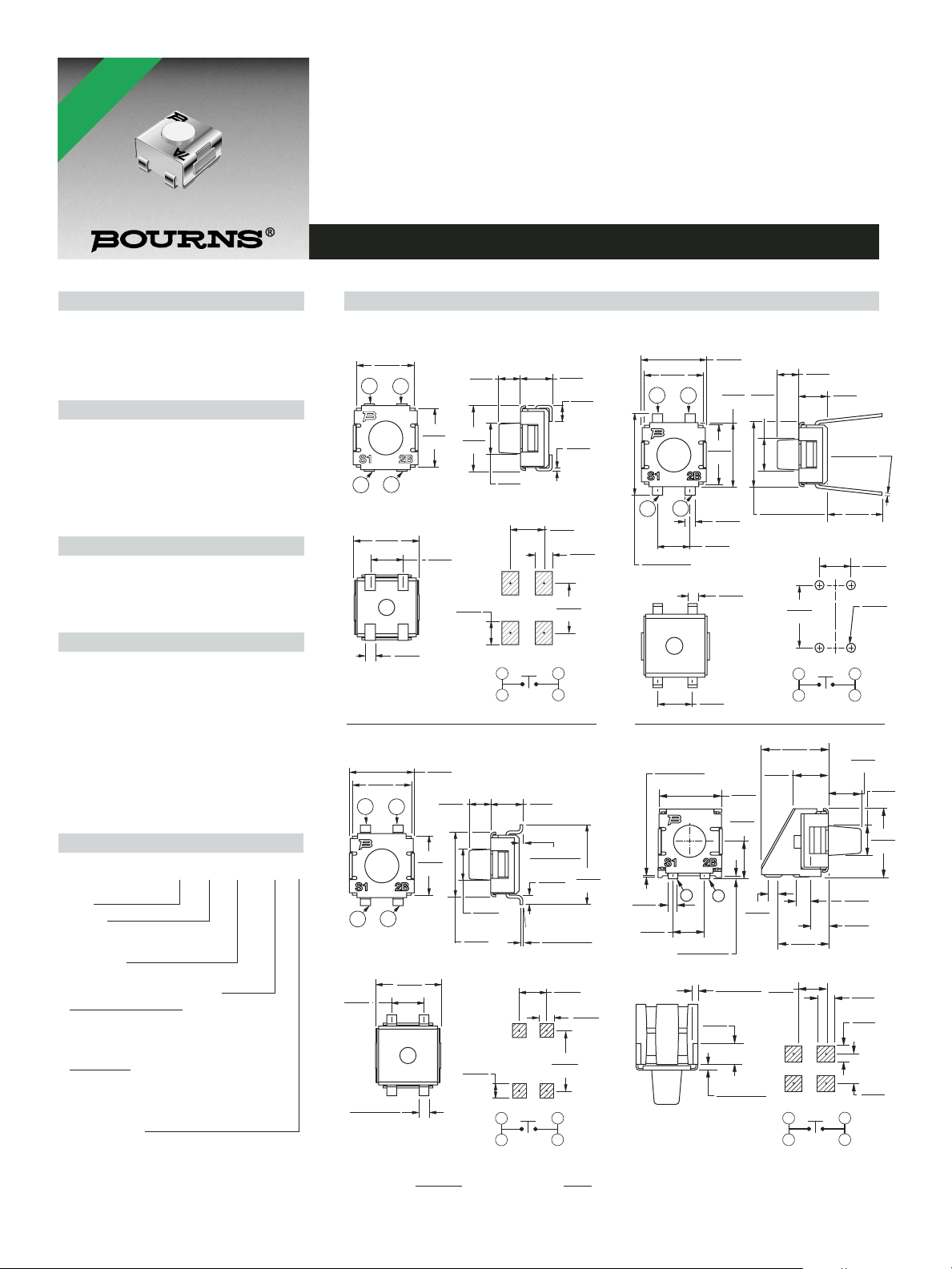
7914 4 mm SMD & Through-hole Sealed Key Switch
Electrical Characteristics
Contact Rating
Maximum Current...............100 mA max.
Maximum Voltage.............................16 V
Contact Resistance .......100 milliohms max.
Insulation Resistance ...100 megohms min.
Dielectric Strength ........................250 VAC
General Characteristics
Switch Type .........................Normally open
Operating Temperature Range
....................................-55 °C to +125 °C
Storage Temperature Range
....................................-55 °C to +125 °C
Seal Test ...........................85 °C Fluorinert
†
Vibration ..............................................20 G
Shock ................................................100 G
Mechanical Characteristics
Actuator Force .........................300 ± 100 g
Pushover Strength (S Style)
...............................2 kilograms minimum
Cycle life, loaded..........100,000 actuations
Contact resistance.......100 milliohms max.
Physical Characteristics
Cover Material......................Stainless steel
Base Material .......Thermoplastic, UL94V-0
Terminal Material .............Phosphor bronze
Dome Material......................Stainless steel
Actuator Material.............High temperature
silicon rubber
Marking......................Manufacturer’s code
and date code
Packaging Options
J & G .............500 pcs./reel; 50 pcs./tube
S..........................................200 pcs./reel
H ..........................................50 pcs./tube
Features
■ Compatible with most surface mount ■ Meets EIA/EIAJ/IPC/VRCI SMD standard
soldering processes outline dimensions
■ Compatible with popular vacuum pick-and- ■ Top or side actuated
place equipment
■
RoHS compliant*
■ J-hook, gull-wing & pinned configurations
■ Sealed for board washing
How to Order
7914 J - 1 - 000 E
Model
Terminal
J = J-Hook H = Through-hole
G = Gull Wing S = Right Angle
Switch Type
1 = N.O. Au Contacts
Product Code for Button Height
(For Styles J, G and H)
000 = 4.0 mm FMS
024 = 2.4 mm FMS (Flush Actuator)
032 = 3.2 mm FMS
050 = 5.0 mm FMS (Tube packaging only)
(For Style S)
000 = 1.68 mm FTS
032 = 0.91 mm FTS
024 = Flush Actuator
050 = 2.7 mm FTS
Embossed Tape
(Option applicable to Styles J, G and S only -
Consult factory. Omit for Style J & G tube
packaging.)
G, J = 500 pcs./reel S = 200 pcs./reel
FMS = From Mounting Surface
FTS = From Top Surface
Product Dimensions
EXCEPT WHERE NOTED.
DIMENSIONS :
MM
(INCHES)
TOLERANCES :
0.2
(.008)
*RoHS COMPLIANT
7914J
J-Hook
4.50
(.177)
2
1
4.50
(.177)
2
1
5.00
(.197)
7914G
Gull Wing
4.50
(.177)
1
1
2.54
(.100)
0.76 ± 0.10
(.030 ± .004)
TYP.
2
0.76
(.030)
2
5.00
(.197)
2.54
(.100)
TYP.
4.93
(.194)
1.65
(.065)
4.50
(.177)
1.65
(.065)
5.00
(.197)
2.39
DIA.
(.094)
RECOMMENDED PCB LAYOUT
1.78
(.070)
TYP.
1
1
2.39
DIA.
(.094)
5.00
(.197)
RECOMMENDED PCB LAYOUT
1.27
(.050)
TYP.
1
1
SPST N.O.
2.54
(.100)
0.28 ± 0.20
(.011
±5° TYP.
SPST N.O.
2.54
(.100)
± .008)
0.60
(.024)
TYP.
0.20 ± 0.08
(.008
(.216)
2.54
(.100)
(.008)
3.81
(.150)
2
2
± .003)
2.54
(.100)
5.50
2
2
1.23
(.048)
TYP.
0.20
1.27
(.050)
TYP.
6.20
(.244)
1.27
(.050)
TYP.
7914H
Through-hole
4.50
(.177)
1
1
6.20 ± 1.00
(.244 ± .039)
7914S
Right Angle
0.13 ± 0.05
(.005
0.76
(.030)
2.54
(.100)
2
2
± .002)
1
0.2 ± 0.13
(.008
4.50
(.177)
2.54
(.100)
2 PLCS.
2.54
(.100)
± .005)
(.015
1.50
(.059)
5.00
(.197)
2.39
5.00
(.094)
(.197)
DIA.
TYP.
5.00 +0.10/-0.15
0.76
(.197 +.004/-.006)
(.030)
RECOMMENDED PCB LAYOUT
0.76
(.030)
TYP.
2 PLCS.
(.204)
2.75
(.108)
5.00
(.197)
2.86
(.113)
2
0.78
(.031)
RECOMMENDED PCB LAYOUT
0.38 ± 0.2
0.48 ± 0.2
(.019
± .008)
± .008)
2.54
(.100)
5.00
(.197)
1
1
5.18
3.89
(.153)
1
1
SPST N.O.
1.65
(.065)
0.20 ± 0.10
(.008 ± .004)
SPST N.O.
2.17
(.085)
2
2
4.00
(.157)
2
2
(.066)
0.89
(.035)
1.5
(.059)
1.3
(.051)
1.25
(.049)
1.68
2.54
(.100)
0.80
(.031)
2.33
(.092)
DIA.
2.38
(.094)
5.44
(.214)
DIA.
TYP.
TYP.
Specifications are subject to change without notice.
Customers should verify actual device performance in their specific applications.
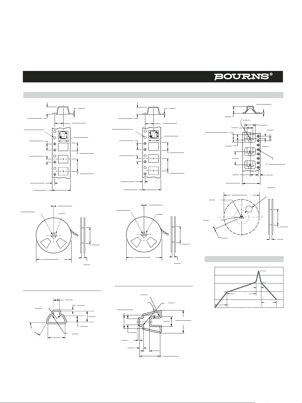
TAPE
REEL
Meets EIA specification 481.
.30
MAX.
(.012)
4.3 ± .10
(.169 ± .004)
5.50 ± 0.05
(.217 ± .002)
1.5 + .10/ –.00
(.059 + .004/ –.00)
DIA.
4.00 ± .10
(.157 ± .004)
5.26 ± .10
(.207 ± .004)
5.26 ± .10
(.207 ± .004)
8.00 ± .20
(.315 ± .008)
12.00 ± .30
(.472 ± .012)
1.75 ± .10
(.069 ± .004)
2.00 ± .05
(.079 ± .002)
13.0 ± .50
(.512 ± .020)
DIA.
20.0
(.787)
DIA.
1.5 ± .254
(.059 ± .010)
EQUAL SPACED 3 PLCS.
178 ± 2
(7.008 ± .079)
DIA.
12.4
(.488)
50.0
(1.969)
MIN.
TAPE
178 ± 2
(7.008 ± .079)
DIA.
13.0 ± .50
(.512 ± .020)
DIA.
1.5 ± .254
(.059 ± .010)
EQUAL SPACED 3 PLCS.
20.0
(.787)
DIA.
50.0
(1.969)
MIN.
12.4
(.488)
REEL
4.3 ± .10
(.169 ± .004)
.30
MAX.
(.012)
5.50 ± 0.05
(.217 ± .002)
1.5 + .10/ –.00
(.059 + .004/ –.00)
DIA.
4.00 ± .10
(.157 ± .004)
2.00 ± .05
(.079 ± .002)
8.00 ± .20
(.315 ± .008)
1.75 ± .10
(.069 ± .004)
12.00 ± .30
(.472 ± .012)
5.26 ± .10
(.207 ± .004)
6.48 ± .10
(.255 ± .004)
Meets EIA specification 481.
7914J/G
2.82
(.111)
.508
(.020)
TYP
2 PLCS
2.82
(.111)
4.69
(.185)
7.67
(.302)
R
.508
(.020)
TYP
R
.762
(.030)
MAX 2 PLCS
60º± 2º
7914H
5.66 ± .254
(.223 ± .010)
8.89 ± .254
(.350 ± .010)
8.64 ± .254
(.340 ± .010)
2.82
(.111)
.508
(.020)
TYP
1.78
(.070)
2.54
(.100)
4.24
(.167)
R TYP
.508
(.020)
R MAX TYP
.762
(.030)
13º ± 2º 2 PLCS REF
7914J 7914G 7914S
6.0
(.236)
0.3 ± 0.05
(.012 ± .002)
10.0
(.394)
2.0
(.079)
7.5
(.295)
12.0
(.472)
4.0
(.157)
1.75
(.069)
16.0 ± 0.3
(.630 ± .012)
5.3
(.209)
5.4
(.213)
7.4 + 0.25/ -0.10
(.291 + .010/ - .004)
0
1.5
(.059)
MIN
0
1.5 + 0.1/0
(.059 + .004/0)
50.0
(1.969)
16.0
(.630)
MIN.
177.8 ± 2.032
(7.00 ± .080)
DIA.
40.0
(1.575)
MIN. DIA.
ACCESS HOLE
AT SLOT LOCATION
16.0
(.630)
DIA.
20.19
(.795)
MIN. DIA.
1.49
(.059)
MIN. EQUAL SPACED 3 PLCS
Packaging Specifications
7914 4 mm SMD & Through-hole Sealed Key Switch
500 pcs./reel
500 pcs./reel
200 pcs./reel
50 pcs./tube
50 pcs./tube
Reflow Soldering Profile
Temperature (°C)
Time (Seconds)
275
30-40 Sec.
120 °C
225
175
125
75
25
0 20 40 60 80 100 120 140 160 180 200
80-90 Sec.
10-15
Sec.
35-60
Sec.
180 °C
250 °C
REV. 07/07
 Loading...