

BOURNS 3400 Service Manual
Specifications are subject to change without notice. 257
I. Product Selection Guide.............................................................258
II. Potentiometers
Multiturn..............................................................................260
Single-Turn..........................................................................265
Knobpot®.............................................................................270
Pushbutton (Digital Readout)..............................................272
III. Definitions & Test Procedures....................................................274
Precision Potentiometers
www.bourns.com

Specifications are subject to change without notice.258
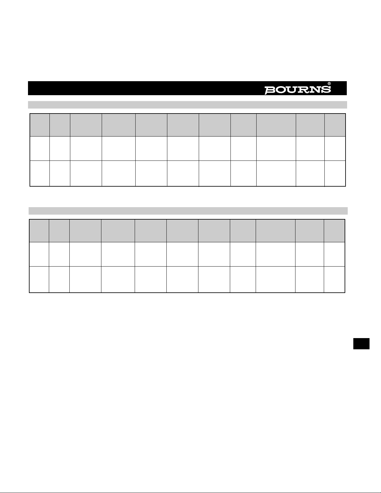
Model Element Resistance
Resistance
Standard Pkg. Pkg. Shaft Page
No.
Turns
Type Tolerance
Range
Linearity Dia. Depth Dia./Length
Mount
No.
(Ohms)
3400 10 Wirewound ±3% 100-500K ±0.15%
1-13/16” 1-3/4” 1/4” X 13/16”
Bushing 260
(30mm) (46mm) (6 X 21mm)
3500 10 Wirewound ±3% 50-100K ±0.20%
7/8” 1” 1/4” X 13/16”
Bushing 261
(22mm) (25mm) (6 X 21mm)
3540 10 Wirewound ±5% 100-100K ±0.25%
7/8” 3/4” 1/4” X 13/16”
Bushing 262
(22mm) (19mm) (6 X 21mm)
3541 10 Hybritron
®
±10% 1K-100K ±0.25%
7/8” 3/4” 1/4” X 13/16”
Bushing 262
(22mm) (19mm) (6 X 21mm)
3543 3 Wirewound ±5% 20-50K ±0.25%
7/8” 3/4” 1/4” X 13/16”
Bushing 263
(22mm) (19mm) (6 X 21mm)
3545 5 Wirewound ±5% 50-50K ±0.25%
7/8” 3/4” 1/4” X 13/16”
Bushing 263
(22mm) (19mm) (6 X 21mm)
3590 10 Wirewound ±5% 200-100K ±0.25%
7/8” 3/4”
Various Bushing 264
(22mm) (19mm)
Model Element Resistance
Resistance
Standard Pkg. Pkg. Shaft Page
No. Type Tolerance
Range
Linearity Dia. Depth Dia./Length
Mount
No.
(Ohms)
6537
Conductive
±10% 1K-100K ±1%
7/8” 1/2” 1/8” X 1/2”
Servo 265
Plastic (22mm) (13mm) (3 X 12.7mm)
6538
Conductive
±10% 1K-100K ±1%
7/8” 19/32” 1/8” X 1/2”
Servo 265
Plastic (22mm) (15mm) (3 X 12.7mm)
6539
Conductive
±15% 1K-100K ±2%
7/8” 19/32” 1/8” X 1/2”
Servo 268
Plastic (22mm) (15mm) (3 x 12.7mm)
6574
Conductive
±10% 1K-100K ±0.1%
2” 19/32” 1/4” X 7/8”
Servo 266
Plastic (51mm) (15mm) (6 X 22mm)
6637
Conductive
±10% 1K-100K ±1%
7/8” 9/16” 1/8” X 7/8”
Bushing 267
Plastic (22mm) (14mm) (3 X 22mm)
6639
Conductive
±15% 1K-100K ±2%
7/8” 21/32” 1/4” X 7/8”
Bushing 268
Plastic (22mm) (17mm) (6 x 22mm)
6657
Conductive
±10% 1K-100K ±1%
1-5/16” 25/32” 1/4” X 7/8”
Bushing 269
Plastic (33mm) (20mm) (6 X 22mm)
Multiturn Precision Potentiometers
Product Selection Guide
Single-Turn Precision Potentiometers
Model Element Resistance
Resistance
Pkg. Pkg. Shaft Page
No.
Turns
Type Tolerance
Range Accuracy
Dia. Depth Dia./Length
Mount
No.
(Ohms)
See
3/4”
See
3600 10 Wirewound ±5% 100-100K Data
(19mm)
Data N/A Bushing 270
Sheet Sheet
See
7/8”
See
3610 10 Wirewound ±5% 100-100K Data
(22mm)
Data N/A Snap-in 271
Sheet Sheet
Model Element Resistance
Resistance
Pkg. Pkg. Shaft Page
No.
Digits
Type Tolerance
Range Accuracy
Dia. Depth Dia./Length
Mount
No.
(Ohms)
See See See
3682 2 Cermet ±3% 50-1 Meg Data Data Data N/A Snap-in 272
Sheet Sheet Sheet
See See See
3683 3 Cermet ±3% 50-1 Meg Data Data Data N/A Snap-in 272
Sheet Sheet Sheet
Specifications are subject to change without notice. 259
Knobpot®Precision Potentiometers
Product Selection Guide
Digital Pushbutton Potentiometers
Specifications are subject to change without notice.260
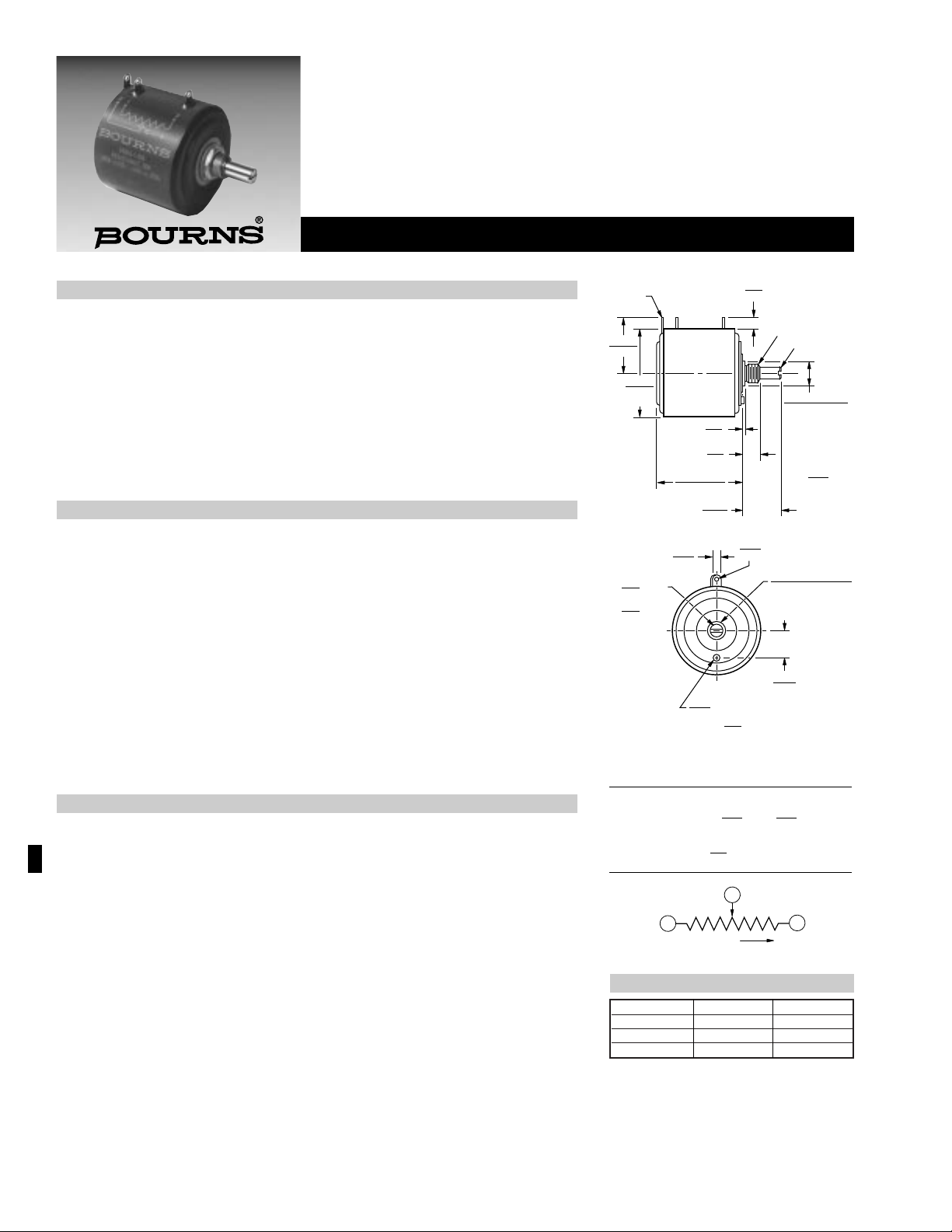
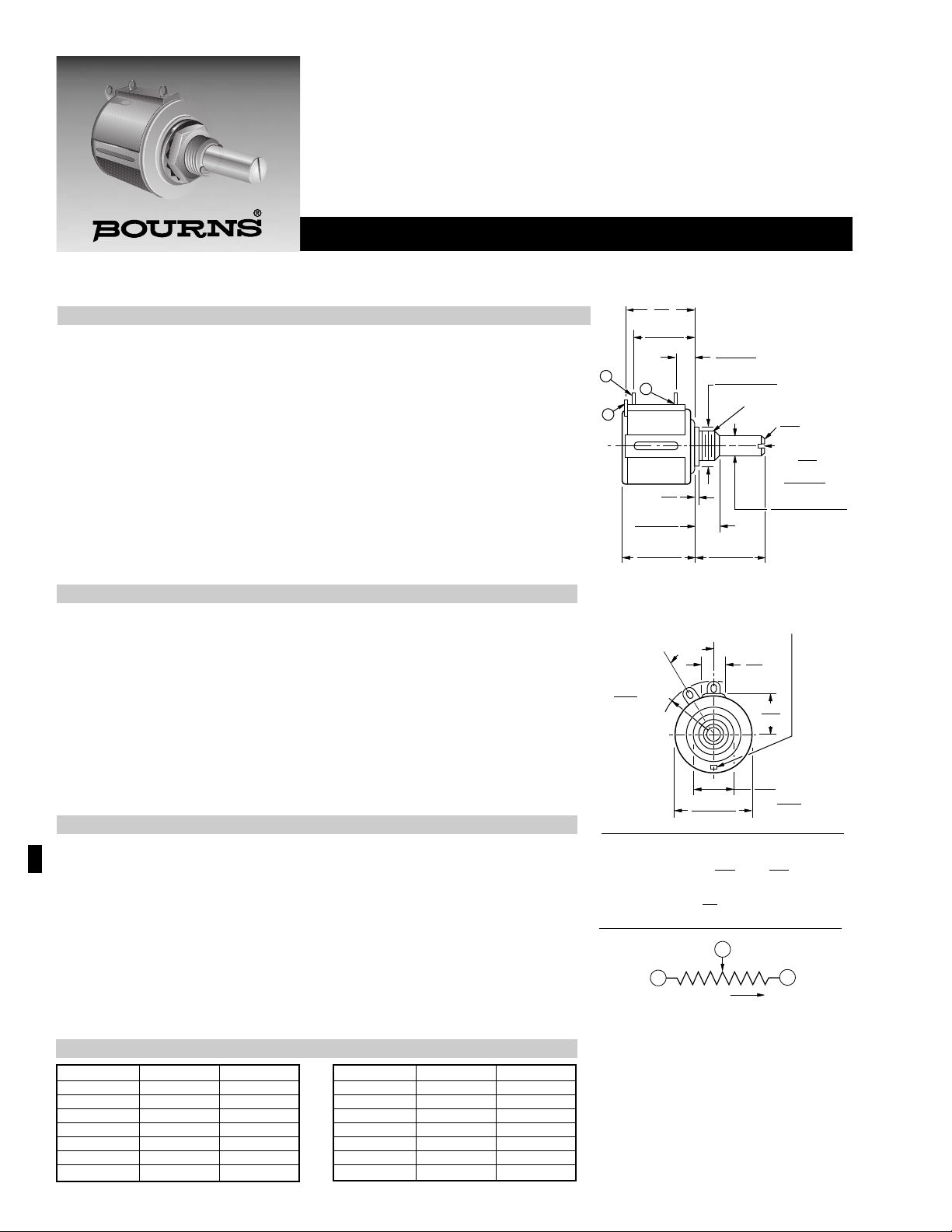
3400 - Precision Potentiometer
Features
■ Bushing mount
■ Optional ±0.05 linearity option
■ Excellent wiper stability
■ High stop strength
■ Sealable
Electrical Characteristics
1
Standard Resistance Range.................................................................100 to 500K ohms
Resistance Tolerance..................................................................................................±3%
Independent Linearity............................................................................................±0.15%
Resolution .........................................................................See recommeded part number
Effective Electrical Angle.............................................................................3600° +4°, -0°
Absolute Minimum Resistance.............1 ohm or 0.15% maximum (whichever is greater)
Noise ........................................................................................100 ohms ENR maximum
Power Rating (Voltage Limited By Power Dissipation, or............................(40°C) 5 watts
1,000 VAC, Whichever Is Less).................................................................(125°C) 0 watt
Dielectric Withstanding Voltage..............................................MIL-STD-202, Method 301
Sea Level.........................................................................................1,000 VAC minimum
80,000 Feet ........................................................................................300 VAC minimum
Insulation Resistance (500 VDC) ..............................................1,000 megohms minimum
Environmental Characteristics
1
Operating Temperature
Static Operation Temperature Range....................................................-65°C to +125°C
Dynamic Temperature Range.................................................................+1°C to +125°C
Temperature Coefficient2 ........................................................±20ppm/°C maximum/unit
Moisture Resistance...........................................MIL-STD-202, Method 103, Condition B
Total Resistance Shift..............................................................................±2% maximum
Vibration.......................................................................................................................10G
Wiper Bounce .........................................................................0.1 millisecond maximum
Total Resistance Shift..............................................................................±2% maximum
Voltage Ratio Shift................................................................................±0.1% maximum
Shock...........................................................................................................................50G
Wiper Bounce .........................................................................0.1 millisecond maximum
Total Resistance Shift..............................................................................±2% maximum
Voltage Ratio Shift................................................................................±0.1% maximum
Load Life............................................................................................1,000 hours, 5 watts
Total Resistance Shift..............................................................................±2% maximum
Rotational Life (No Load) .......................................................2,000,000 shaft revolutions
2
Total Resistance Shift..............................................................................±5% maximum
Mechanical Characteristics
1
Mechanical Angle........................................................................................3600° +4°, -0°
Shaft Runout................................................................................0.002 in. (0.05mm) T.I.R.
Shaft End Play.............................................................................0.005 in. (0.13mm) T.I.R.
Shaft Radial Play .......................................................................0.0025 in. (0.06mm) T.I.R.
Pilot Diameter Runout .................................................................0.002 in. (0.05mm) T.I.R.
Lateral Runout.............................................................................0.005 in. (0.13mm) T.I.R.
Stop Strength...................................................................550 oz.-in. (388 Ncm) minimum
Torque (Starting & Running) ..............................................2.0 oz.-in. (1.4 Ncm) maximum
Backlash......................................................................................................1.0° maximum
Weight................................................................................................Approximately 110G
Terminals.......................................................................................Gold-plated solder lugs
Markings....................................Manufacturer’s name and part number, resistance value
and tolerance, linearity tolerance, wiring diagram, date code
Ganging ..................................................................................................2 cups maximum
WIPER
1-13/16
(46.04)
DIA.
29.37
(1-5/32)
3/8"-32 2A THD UNEF
CCW CW
45° X .25
CHAMFER
10.32 + .00/ - .05
(.4062 + .000/ -.002)
PILOT DIA.
7.94
5/16
20.64
(13/16)
1.52
(.06)
39.4
ADD
(1.55)
FOR
ADDITIONAL CUP
4.76
(3/16)
TYP.
2.36
(.093)
DIA. TYP.
6.34 + .00/ - .01
(.2497 + .0000/ - .0003)
SHAFT DIA.
3.18
(.125)
14.3
(9/16)
1.02
(.04)
NOTE: LOCKWASHER AND HEX NUT TO BE
SUPPLIED WITH EACH UNIT.
1
3
CW
CLOCKWISE
CCW
2
WIPER
6.35
(1/4)
WIDE
SLOT
X
1.02
(.04)
DEEP
EXTENDS
1.02
(.04)
PAST MOUNTING SURFACE
44.45 ± .79
(1-3/4 ± 1/32)
TOLERANCES: EXCEPT WHERE NOTED
.25 .13
DECIMALS: .XX ±
(.010),
.XXX ±
(.005)
FRACTIONS: ±1/64
MM
DIMENSIONS:
( IN.)
DIA. ANTI-ROTATION PIN
1
At room ambient: +25°C nominal and 50% relative humidity nominal, except as noted.
2
Consult manufacturer for complete specification details for resistances below 500 ohms and above 100K ohms.
Part Number Resistance Resolution
3400S-1-102 1,000 .020
3400S-1-502 5,000 .013
3400S-1-103 10,000 .010
Recommended Part Numbers
BOLD-FACE LISTINGS ARE IN STOCK AND READILY
AVAILABLE THROUGH DISTRIBUTION.
FOR OTHER OPTIONS CONSULT FACTORY.
Specifications are subject to change without notice. 261
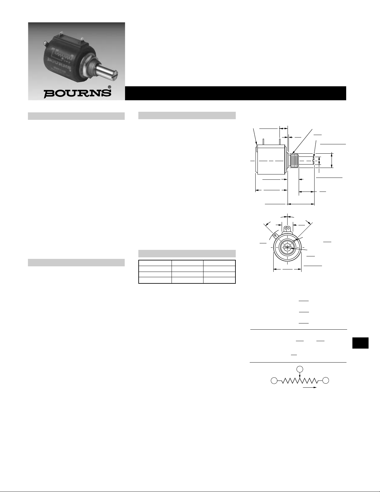
3500 - Precision Potentiometer
.25
(.010)
X 45° CHAMFER
WIPER
3/8"-32 2A THD UNEF
CCW
12.7
(1/2)
8.0 ± .38
(.315 ± .015)
NOTE: LOCKWASHER AND HEX NUT TO BE
SUPPLIED WITH EACH UNIT.
NOTE: SHAFT LENGTH VARIATIONS
3500S-1-RC
3500S-2-RC
3501H-1-RC
CW
3500S-2/3501H-1
5.46 ± .76
(.215 ± .030)
1.52
(.06)
25.4 ± .51
(1.00 ± .02)
10.32 + .00/ - .05
(.4062+.000/-.002)
PILOT DIA.
.6.34 + .00/- .01
(.249+.0000/-.0003)
REF.
20.64 ±.79
(13/16 ± 1/32)
DIA.
22.23
(7/8)
ADJUSTMENT SLOT
LOCATION OF OPTIONAL
A/R PIN ON R
45° ± 5°
8.9
(.35)
45° ± 5°
16.0
(.63) R
MAX.
TOLERANCES: EXCEPT WHERE NOTED
.25 .13
DECIMALS: .XX ±
(.010),
.XXX ±
(.005)
FRACTIONS: ±1/64
MM
DIMENSIONS:
(IN.)
1
3
CW
CLOCKWISE
CCW
2
WIPER
WIDE X
.81
(.032)
DEEP
.81 ± .25
(.032 ± .010)
11/16
(17.46)
13/16
(20.64)
13/16
(20.64)
.29
(7.37)
1
At room ambient: +25°C nominal and 50% relative humidity nominal, except as noted.
2
Consult manufacturer for complete specification details for resistances below 500 ohms.
Features
■ Bushing mount
■ Sealable
■ Non-standard features and specifications
available
■ Optional high torque feature
■ Optional center tap feature
■ Gangable
Electrical Characteristics
1
Standard Resistance Range
...................................50 to 200K ohms
Resistance Tolerance.......................±3%
Independent Linearity.................±0.20%
Resolution
...........See recommeded part numbers
Effective Electrical Angle
.....................................3600° +10°, -0°
Absolute Minimum Resistance/Minimum
Voltage
.....................1 ohm or 0.1% maximum
(whichever is greater)
Noise ..............100 ohms ENR maximum
Power Rating (Voltage Limited By Power
Dissipation or 325 VAC, Whichever Is Less)
+70°C........................................2 watts
+125°C........................................0 watt
Dielectric Withstanding Voltage
MIL-STD-202, Method 301
Sea Level..............1,500 VAC minimum
70,000 Feet .............400 VAC minimum
Insulation Resistance
(500 VDC)....1,000 megohms minimum
Environmental Characteristics
1
Operating Temperature
Static Operation Temp Range
...................................-65°C to +125°C
Dynamic Temp Range
.....................................+1°C to +125°C
Temperature Coefficient
2
...................±50ppm/°C maximum/unit
Vibration............................................20G
Wiper Bounce
.....................0.1 millisecond maximum
Total Resistance Shift...±2% maximum
Voltage Ratio Shift.....±0.1% maximum
Shock..............................................100G
Wiper Bounce
.....................0.1 millisecond maximum
Total Resistance Shift...±2% maximum
Voltage Ratio Shift.....±0.1% maximum
Load Life.................1,000 hours, 2 watts
Total Resistance Shift...±2% maximum
Rotational Life (No Load)
..................2,000,000 shaft revolutions
2
Total Resistance Shift...±5% maximum
Moisture Resistance.........MIL-STD-202,
Method 103,Condition B
Total Resistance Shift...±2% maximum
Part Number Resistance Resolution
3500S-2-102 1,000 .030
3500S-2-502 5,000 .018
3500S-2-103 10,000 .019
Recommended Part Numbers
Mechanical Characteristics
1
Mechanical Angle ...........3600° +10°, -0°
Shaft Runout
.......................0.002 in. (0.05mm) T.I.R.
Lateral Runout
.......................0.005 in. (0.13mm) T.I.R.
Pilot Diameter Runout
.......................0.002 in. (0.05mm) T.I.R.
Shaft End Play
.......................0.005 in. (0.13mm) T.I.R.
Shaft Radial Play
.......................0.003 in. (0.08mm) T.I.R.
Stop Strength
.....................96 oz.-in. (67.8 Ncm) min.
Torque (Starting & Running)
...................0.6 oz.-in. (0.42 Ncm) max.
Backlash...........................1.0° maximum
Weight.......................Approximately 28G
Terminals............Gold-plated solder lugs
Ganging .......................2 cups maximum
BOLD-FACE LISTINGS ARE IN STOCK AND READILY
AVAILABLE THROUGH DISTRIBUTION.
FOR OTHER OPTIONS CONSULT FACTORY.
Specifications are subject to change without notice.262
3540/3541 - Precision Potentiometer
3540 3541
Wirewound Element Hybritron
®
Element
Electrical Characteristics
1
Standard Resistance Range ..........100 to 100K ohms..................1K to 100K ohms
Resistance Tolerance......................±5% ......................................±10%
Independent Linearity ....................±0.25% ..................................±0.25%
Resolution ......................................See recommended part numbers Essentially infinite
Effective Electrical Angle................3600° +10°, -0° ......................3600° +10°, -0°
Absolute Minimum Resistance/......1 ohm or 0.1% maximum ......Minimum voltage
Minimum Voltage (whichever is greater) 0.2% maximum
Noise ..............................................100 ohms ENR maximum......Output smoothness 0.1%
maximum
Power Rating (Voltage Limited
By Power Dissipation or
447 VAC, Whichever Is Less)
+70°C ..........................................2 watts ..................................2 watts
+125°C ........................................0 watt ....................................0 watt
Dielectric Withstanding Voltage......MIL-STD-202, Method 301....MIL-STD-202, Method 301
Sea Level ....................................1,000 VAC minimum..............1,000 VAC minimum
Insulation Resistance
(500 VDC) ....................................1,000 megohms minimum ....1,000 megohms minimum
Environmental Characteristics
1
Operating Temperature
Static Operation Temp Range......-55°C to +125°C ....................-55°C to +125°C
Dynamic Temp Range..................+1°C to +125°C......................+1°C to +125°C
Temperature Coefficient
2
..............±50ppm/°C maximum/unit ....±100ppm/°C maximum/unit
Vibration..........................................15G ........................................15G
Wiper Bounce..............................0.1 millisecond maximum......0.1 millisecond maximum
Shock..............................................50G ........................................50G
Wiper Bounce..............................0.1 millisecond maximum......0.1 millisecond maximum
Load Life ........................................1,000 hours, 2 watts ..............1,000 hours, 2 watts
Total Resistance Shift ..................±2% ......................................±5%
Rotational Life (No Load)................1,000,000 shaft revolutions
2
..5,000,000 shaft revolutions
2
Total Resistance Shift ..................±5% maximum ......................±5% maximum
Moisture Resistance ......................MIL-STD-202, Method 103, ..MIL-STD-202, Method 103,
Condition B Condition B
Total Resistance Shift ..................±2% maximum ......................±5% maximum
Mechanical Characteristics
1
Mechanical Angle ..........................3600° +10°, -0° ......................3600° +10°, -2°
Shaft Runout ..................................0.003 in. (0.08mm) T.I.R. ........0.003 in. (0.08mm) T.I.R.
Lateral Runout................................0.005 in. (0.13mm) T.I.R.........0.005 in. (0.13mm) T.I.R.
Pilot Diameter Runout ....................0.003 in. (0.08mm) T.I.R.........0.003 in. (0.08mm) T.I.R.
Shaft End Play................................0.012 in. (0.30mm) T.I.R.........0.012 (0.30mm) T.I.R.
Shaft Radial Play ............................0.003 in. (0.08mm) T.I.R. ........0.003 (0.08mm) T.I.R.
Stop Strength ................................75 oz-in. (53 Ncm) minimum..75 oz.-in. (53 Ncm) minimum
Torque (Starting & Running)............0.6 oz.-in. (0.35 Ncm) max. ..0.6 oz.-in. (0.35 Ncm) max.
Backlash ........................................1.0° maximum........................1.0° maximum
Weight ............................................Approximately 21G ................Approximately 22.5G
Terminals ........................................Gold-plated solder lugs ........Gold-plated solder lugs
Ganging..........................................2 cups maximum....................2 cups maximum
3540S-1/3541H-1
1
5.72 ± .38
(.225±.015)
10.32 +.00/.05
(.406+.000/-.002)
3/8" 32-UNEF-2ATHD
ADJUSTMENT
SLOT
.81
WIDE
X
.81±.25
DEEP
2
3
1.52
(.06)
7.92 ± .38
(.312 ± .015)
19.05 ± .38
(.750 ± .015)
30°
± 5°
6.35
(.25)
22.23 ± .38
(.875 ± .015)
MTG. FACE
12.45
(.49)
OPTIONAL ANTIROTATION LUG
(-91) 1.42 X .50 ON 7.4 RADIUS.
LENGTH 1.27 FROM MOUNTING SURFACE.
(SUGGESTED PANEL HOLE 1.6 DIA.)
1
3
CW
CLOCKWISE
CCW
2
WIPER
18.3
(.72)
14.35 ± .38
(.565±.015)
DIA.
(.032)
(.032±.010)
6.342 + .000/ - .008
(.2497+.0000/-.0003)
DIA.
20.62 ± .79
(.812 ± .031)
15.88
(.625)
DIA. MIN.
15.88
(.625)
TOLERANCES: EXCEPT WHERE NOTED
.25 .13
DECIMALS: .XX ±
(.010),
.XXX ±
(.005)
FRACTIONS: ±1/64
MM
DIMENSIONS:
(IN.)
.25
(.010)
X 45° CHAMFER
R MAX.
1
At room ambient: +25°C nominal and 50% relative humidity nominal, except as noted.
2
Consult manufacturer for complete specification details.
Features
■ Bushing mount
■ Optional center tap and rear
shaft extension
■ Optional AR lug feature
■ Gangable with common or concentric
shafts
■ High torque available
■ Optional 0.1% linearity
■ Non-standard features and specifications
available
Part Number Resistance Resolution
3540S-1-201 200 .042
3540S-1-501 500 .031
3540S-1-102 1,000 .027
3540S-1-202 2,000 .021
3540S-1-502 5,000 .021
3540S-1-103 10,000 .019
3540S-1-203 2,000 .014
Recommended Part Numbers
Part Number Resistance Resolution
3540S-1-103 10,000 .019
3540S-1-203 20,000 .014
3540S-1-503 50,000 .011
3540S-1-104 100,000 .008
3541H-1-102 1,000 .027
3541H-1-502 5,000 .021
3541H-1-103 10,000 .019
BOLD-FACE LISTINGS ARE IN STOCK AND READILY
AVAILABLE THROUGH DISTRIBUTION.
FOR OTHER OPTIONS CONSULT FACTORY.
 Loading...