

BOURNS 3329 Service Manual
Features
4.57
(.180)
45° REF.
90° ± 5°
31
2
.46 ± .05
(.018 ± .002)
6.35 ± .51
(.250 ± .020)
6.78 ± 2.24
(.267 ± .088)
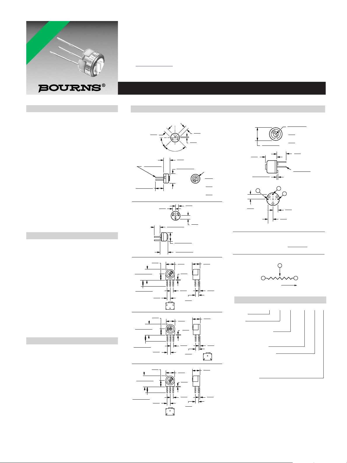
3329H
13
2
3329P
5.82 ± .25
(.229 ± .010)
13
2
3329S
6.10
(.240)
.89
(.035)
6.60
(.260)
.38
(.015)
7.75 ± 2.97
(.305 ± .117)
8.38 ± .51
(.330 ± .020)
5.08
(.200)
31
2
3329W
13
2
3329X
3329P-DK9-RC
6.35 ± .51
(.250 ± .020)
5.79
(.228)
4.75
(.187)
.46 ± .05
(.018 ± .002)
.43 ± .13
(.017 ± .005)
2.54
(.100)
1
2
3
ADJ. SLOT
2.79 ± .038
(.110 ± ..001)
.64
(.025)
.51
(.020)
2.54
(.100)
2.54
(.100)
WIDE
X
X
DEEP
DIA.
MIN.
DIA. 3 PINS
2.54
(.100)
2.54
(.100)
2.54
(.100)
2.54
(.100)
2.54
(.100)
2.54
(.100)
2.54
(.100)
2.54
(.100)
2.54
(.100)
2.54
(.100)
2.54
(.100)
2.54
(.100)
2.54
(.100)
6.10
(.240)
6.10
(.240)
5.08
(.200)
5.08
(.200)
6.60
(.260)
6.60
(.260)
.89
(.035)
.89
(.035)
2.54
(.100)
.38
(.015)
DIA. TYP.
6.78 ± 2.24
(.267 ± .088)
6.35 ± .51
(.250 ± .020)
7.75 ± 2.97
(.305 ± .117)
7.75 ± 2.97
(.305 ± .117)
8.38 ± .51
(.330 ± .020)
8.38 ± .51
(.330 ± .020)
.38
(.015)
.38
(.015)
ADJ. SLOT
3.56
(.140)
.64
(.025)
1.02
(.040)
WIDE
X
X
DEEP
LONG
1 3
2
CCW CW
CLOCKWISE
WIPER
*RoHS COMPLIANT
VERSIONS
AVAILABLE
■ 1/4” Round / Single-Turn / Cermet
Industrial / Sealed
■ 5 standard terminal styles
■ Tape and reel packaging available
■ Listed on the QPL for style RJ50 per
MIL-PRF-22097 and RJR50 per
High-Rel MIL-PRF-39035
■ RoHS compliant* version available
3329 - 1/4 ” Round Trimming Potentiometer
Electrical Characteristics
Standard Resistance Range
...................................10 to 1 megohm
Resistance Tolerance ............±10 % std.
Absolute Minimum Resistance
......................................1 % or 2 ohms
Contact Resistance Variation
..........................3.0 % or 3 ohms max.
Adjustability
Voltage....................................±0.05 %
Resistance ..............................±0.15 %
Resolution.....................................Infinite
Insulation Resistance ................500 vdc.
Dielectric Strength
Sea Level .................................600 vac
80,000 Feet ..............................250 vac
Adjustment Angle ..................240 ° nom.
Environmental Characteristics
Power Rating @ 85 °C (300 volts max.)
.................................................0.5 watt
Power Rating @ 150 °C.................0 watt
Temperature Range ....-55 °C to +150 °C
Temperature Coefficient ....±100 ppm/°C
Seal Test........................85 °C Fluorinert
Humidity........MIL-STD-202 Method 106
Vibration.........30 G (1 % ∆TR; 1 % ∆VR)
Shock...........100 G (1 % ∆TR; 1 % ∆VR)
Load Life
..............1,000 hours 0.5 watt @ 85 °C
Rotational Life ........................200 cycles
Physical Characteristics
Mechanical Angle ..................260 ° nom.
Torque .............................5.0 oz-in. max.
Stop Strength ..................5.0 oz -in. min.
Terminals ........................Solderable pins
Weight ........................................0.02 oz.
Marking .........Manufacturer’s trademark,
Wiper................50 % (Actual TR) ±10 %
Standard Packaging .....50 pcs. per tube
Adjustment Tool ..............................H-90
*RoHS Directive 2002/95/EC Jan 27 2003 including Annex.
†“Fluorinert” is a registered trademark of 3M Co.
Specifications are subject to change without notice.
Customers should verify actual device performance in their specific applications.
(see standard resistance table)
(closer tolerance available)
(whichever is greater)
(whichever is greater)
manufacturer’s model number
1,000 megohms min.
96 hours
(3 % ∆TR, 10 Megohms IR)
except “P” pin style
resistance code, date code,
(3 % ∆TR; 3 % CRV)
(4 % ∆TR; 4 % CRV)
and style
†
Product Dimensions
TOLERANCES: ± 0.25 (.010) EXCEPT WHERE NOTED
DIMENSIONS ARE:
MM
(INCHES)
How To Order
3329 M - 1 - 103 __ LF
Model
Style
Standard or Modified
Product Indicator
-1 = Standard Product
-DK9 = Plastic Spacer
Resistance Code
Packaging Designator
Blank = Tube (Standard)
R = Tape and Reel (M and U Pin Styles
Only)
A = Ammo Pack (M and U Pin Styles Only)
Terminations
LF = 100 % Tin-plated (RoHS compliant)
Blank = 90 % Tin / 10 % Lead-plated
(Standard)
Consult factory for other available options.
3329 - 1/4 ” Round Trimming Potentiometer
Standard Resistance Table
Resistance Resistance
(Ohms) Code
10 100
20 200
50 500
100 101
200 201
500 501
1,000 102
2,000 202
5,000 502
10,000 103
20,000 203
25,000 253
50,000 503
100,000 104
200,000 204
250,000 254
500,000 504
1,000,000 105
Popular distribution resistance values listed in
boldface. Special resistances available.
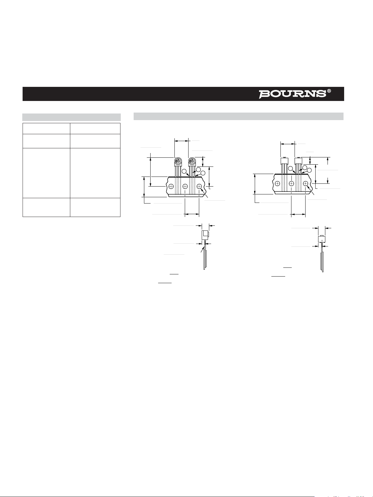
Packaging Specifications
SIDE ADJUST
3329M-1
3
6.1 ± .25
(.240 ± .010)
3.43 ± .25
(.135 ± .010)
DIA. TYP.
(.500)
26.4 ± .76
(1.039 ± .030)
18 + 1.0/ - 0.5
(.709 + .039/ .020)
12.70 + 0.3/ - 0.25
(.500 + .012/ - .010)
.43 ± .05
(.017 ± .002)
MM
(INCHES)
2.54
(.100)
ALL PINS IN-LINE ON CENTER
DIMENSIONS:
1000/REEL/BOX
12.70
REF.
9.4 ± .5
(.370 ± .020)
2
1
(.157 ± .012)
4.0 ± 0.3
DIA.
TOP ADJUST
3329U-1
3
18 + 1.0/ - 0.5
(.709 + .039/ .020)
12.70 + 0.3/ - 0.25
(.500 + .012/ - .010)
6.35 ± .5
(.250 ± .020)
2.79 ± .25
(.110 ± .010)
MM
(INCHES)
2.54
(.100)
ALL PINS IN-LINE ON CENTER
DIMENSIONS:
1000/REEL/BOX
12.70
(.500)
REF.
6.35
(.250)
2
1
4.0 ± 0.3
(.157 ± .012)
MAX.
24.38 ± 0.76
(.960 ± .030)
18 ± .76
(.709 ± .030)
DIA.
Meets EIA Specification 468.
Specifications are subject to change without notice.
Customers should verify actual device performance in their specific applications.
REV. 09/04
 Loading...