

BOURNS 3315 Service Manual
*RoHS Directive 2002/95/EC Jan 27 2003 including Annex
Specifications are subject to change without notice.
Customers should verify actual device performance in their specific applications.
3315 - 9 mm Square Sealed Incremental Encoder
Features
■ Miniature package for design flexibility
■ Long operating life
■ Conductive plastic element
■ Bushing or PC board mount
■ Quadrature output
■ RoHS compliant versions available*
Electrical Characteristics
Output ..........................................................................................................2-bit gray code, Channel A leads Channel B electrically turning clockwise (CW)
Closed Circuit Resistance ..............................................................................................................................................................................5 ohms maximum
Contact Rating..........................................................................................................................................................................................TTL compatible loads
Insulation Resistance (500 VDC)........................................................................................................................................................1,000 megohms minimum
Dielectric Withstanding Voltage
Sea Level ..................................................................................................................................................................................................900 VAC minimum
Electrical Travel..........................................................................................................................................................................................................Continuous
Contact Bounce ..................................................................................................................................................................................5 milliseconds maximum
RPM (Operating) ..................................................................................................................................................................................................120 maximum
Environmental Characteristics
Operating Temperature Range ........................................................................................................................................-40 °C to +125 °C (-40 °F to +257 °F)
Storage Temperature Range............................................................................................................................................-55 ºC to +125 ºC (-67 °F to +257 °F)
Humidity....................................................................................................................................................................MIL-STD-202, Method 103B, Condition B
Vibration ..............................................................................................................................................................................................................................30 G
Contact Bounce ............................................................................................................................................................................5.0 millisecond maximum
Shock ................................................................................................................................................................................................................................100 G
Contact Bounce ............................................................................................................................................................................5.0 millisecond maximum
Rotational Life ......................................................................................................................................................................................100,000 cycles @ 6 PPR
25,000 cycles @ 16 PPR
IP Rating ..............................................................................................................................................................................................................................IP 67
Mechanical Characteristics
Mechanical Angle ............................................................................................................................................................................................360 ° Continuous
Running Torque ........................................................................................................................................................................3.53 N-cm (5 oz.-in.) maximum
Mounting Torque
Plastic Bushing..................................................................................................................................................................45.19 N-cm (4.0 lb.-in.) maximum
Metal Bushing ........................................................................................................................................................................79 N-cm (7.0 lb.-in.) maximum
Weight ..............................................................................................................................................................................................................4.5 gm (0.15 oz.)
Terminals ............................................................................................................................................................................................................Solderable pins
Soldering Condition
Manual Soldering ..................................................96.5Sn/3.0Ag/0.5Cu solid wire or no-clean rosin cored wire; 370 °C (700 °F) max. for 3 seconds
Wave Soldering............................................................................96.5Sn/3.0Ag/0.5Cu solder with no-clean flux; 260 °C (500 °F) max. for 5 seconds
Wash Processes ..........................................................For recommended wash processes, please refer to http://www.bourns.com/pdfs/sldclen.pdf
Marking................................................................................................................................................Manufacturer’s trademark, part number, and date code
Hardware ..................................................One lockwasher and one mounting nut are shipped with each encoder, except where noted in the part number.
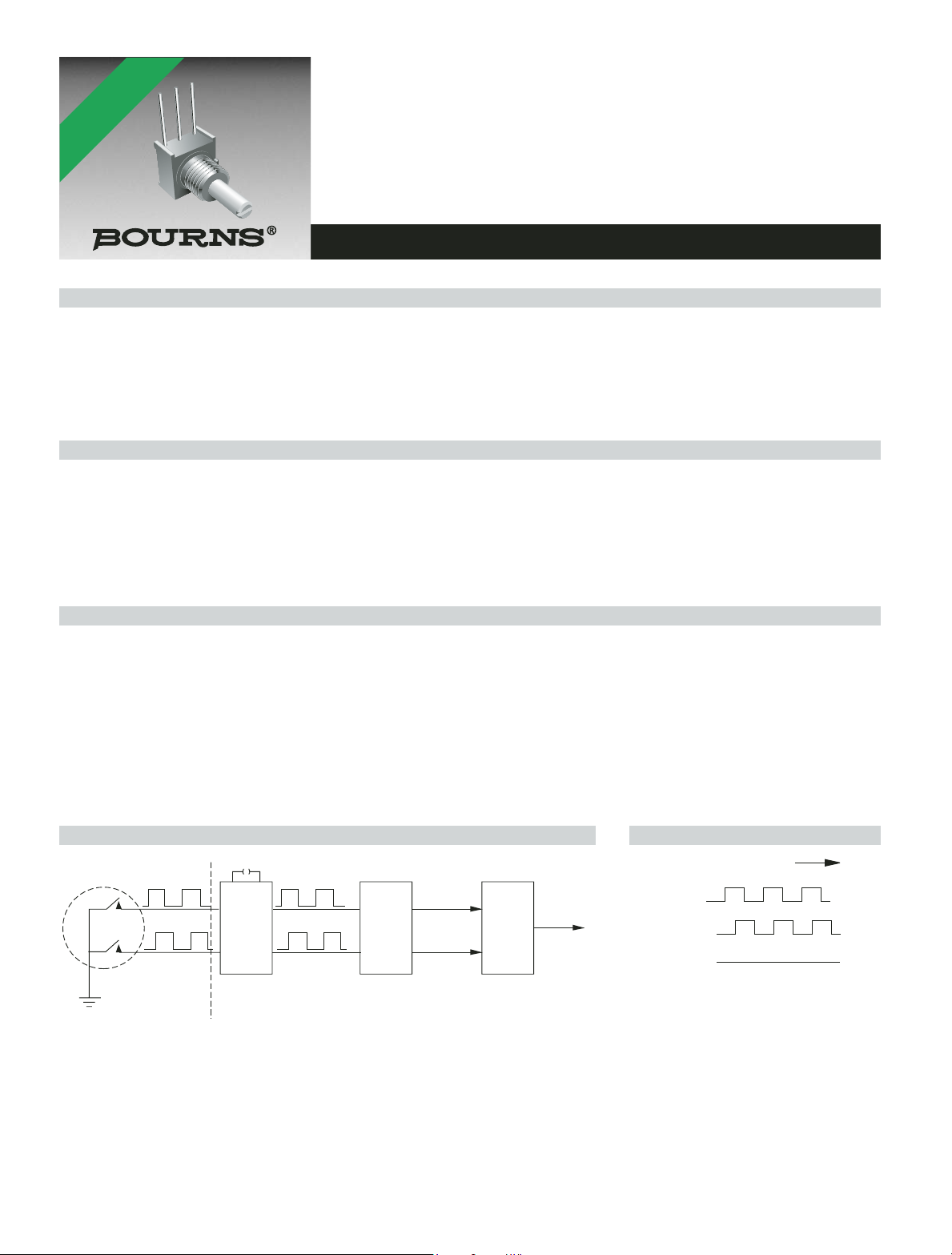
Suggested Incremental Control Diagram
Quadrature Output Table
*RoHS COMPLIANT
VERSIONS
AVAILABLE
.0015 µf
5 ms DELAY
DEBOUNCE
(MC 14490)
97
(CUSTOMER LOGIC CIRCUITRY)
DIRECTION
DECODE
LOGIC
MAGNITUDE
Channel A
UP/DOWN
COUNTER
BINARY
OUTPUT
Channel B
Channel C
Clockwise
3315 - 9 mm Square Sealed Incremental Encoder
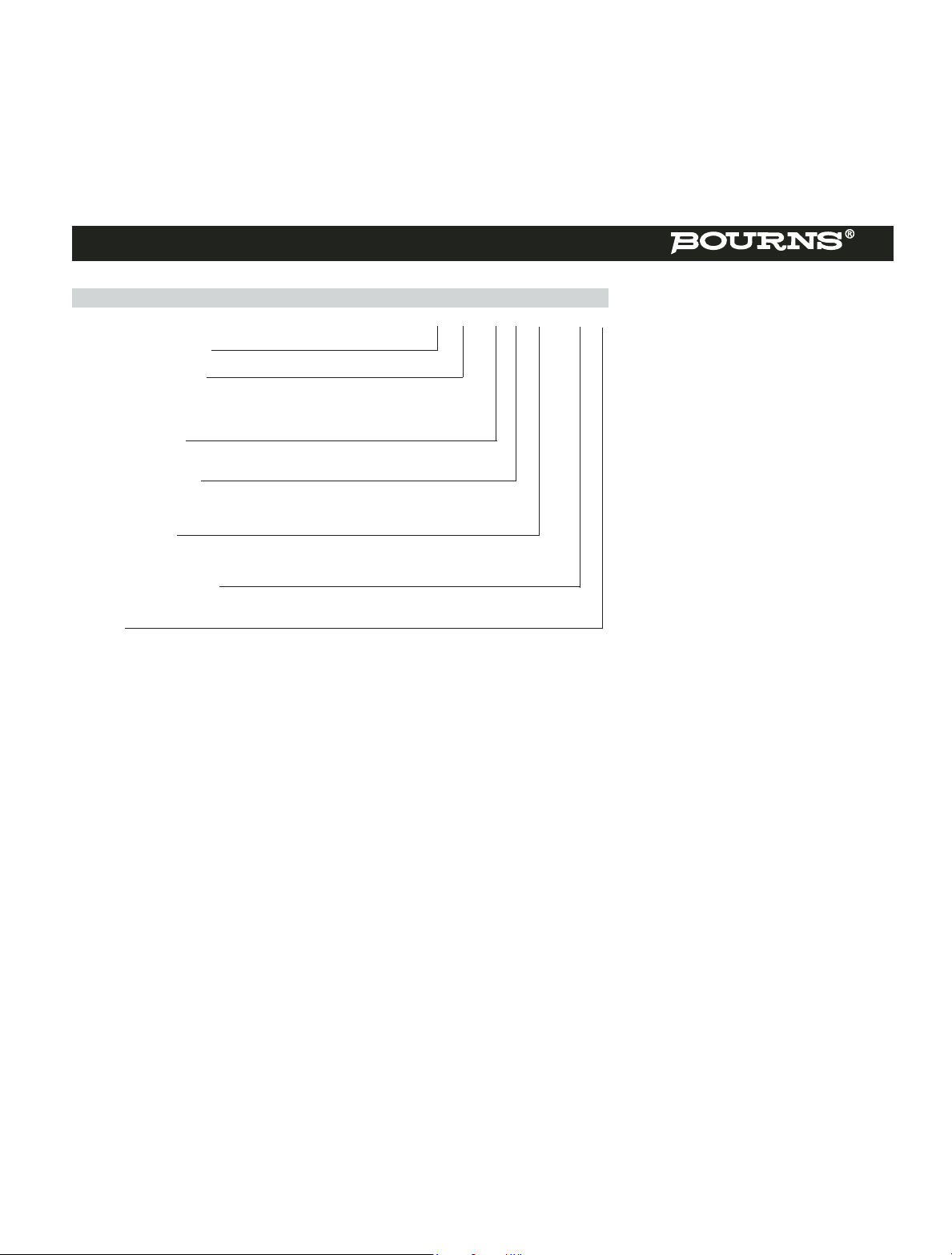
Part Numbering System
3315 Y - 0 0 1 - 006 L
Model Number Designator
3315 = 9 mm Encoder
Terminal Style Designator
C = In-line Straight Terminals Side Exit
R = In-line Terminals Rear Exit
P = 5.08 mm x 2.54 mm Triangular Pattern Rear Exit
Y = 5.08 mm x 5.08 mm Triangular Pattern Rear Exit
Shaft End Designator
0 = Shaft End Slotted
1 = Shaft End Flatted
Shaft Length Designator
0 = 12.7 mm FMS Long Plastic Shaft (Available w/bushing only)
1 = 19.05 mm FMS Long Plastic Shaft (Available w/bushing only)
2 = 5.59 mm FMS (Bushingless version only)
Bushing Designator
1 = 6.35 mm x 6.35 mm Plastic
2 = 6.35 mm x 6.35 mm Ni Plated Brass
5 = Bushingless (Board Level)
Pulses per Revolution Code
006 =6 PPR
016 =16 PPR
Terminals
L = RoHS compliant (100 % tin plated finish)
Blank = Standard (tin/lead plated finish)
Specifications are subject to change without notice.
Customers should verify actual device performance in their specific applications.
 Loading...