

Page 1

VT510 Video Terminal
Installation and Operating Information
Order Number: 598-0013866
Page 2

November 1996
Boundless Technologies makes no representations that the use of its products
in the manner described in this publication will not infringe on existing or
future patent rights, nor do the descriptions contained in this publication imply
the granting of licenses to make, use, or sell equipment or software in
accordance with the description.
DEC, OpenVMS, ULTRIX, VMS, and VT are trademarks of Digital Equipment
Corporation.
ADDS is a trademark of Applied Digital Data Systems, Inc.
IBM, ProPrinter, and PS/2 are registered trademarks of International Business
Machines Corporation.
SCO is a trademark of Santa Cruz Operations, Inc.
TVI is a trademark of TeleVideo, Inc.
UNIX is a registered trademark of UNIX System Laboratories, Inc.
WY and WYSE are registered trademarks of Wyse Technologies.
All other trademarks and registered trademarks are the property of their
respective holders.
© Boundless Technologies, Inc. 1996
All Rights Reserved.
Printed in USA
FCC ID: CR8-VGB10—NOTE: The North American version of this equipment
has been tested and found to comply with the limits for a Class A digital device,
pursuant to Part 15 of FCC Rules. These limits are designed to provide
reasonable protection against harmful interference when the equipment is
operated in a commercial environment. This equipment generates, uses, and
can radiate radio frequency energy and, if not installed and used in accordance
with the instruction manual, may cause harmful interference to radio
communications. Operation of this equipment in a residential area is likely to
cause harmful interference, in which case, the user will be required to correct
the interference at his own expense.
Canadian Standards Association (CSA) Statement
This digital apparatus does not exceed the Class A limits for radio noise
emissions from digital apparatus as set out in the radio interference regulations
of the Canadian Department of Communications.
Le présent appareil numérique n'émet pas de bruits radioélectriques dépassant
les limites applicables aux appareils numériques de class A prescrites dans le
règlement sur le brouillage radioélectrique édicté par le Ministère des
Communications du Canada.
Use of Ozone Depleting Substance (ODS)
The VT510 is in full compliance with the labeling requirements in the US Clean
Air Act Amendments of 1990. It does not contain, nor is it manufactured with, a
Class 1 ODS, as defined in Title VI Section 611 of this act.
Page 3

chapter
1
Contents
Preface Vv
Overview ..................................................................................vv
Environment ............................................................................ vv
Before you Start ....................................................................... vv
Conventions......................................................................... viivii
Proper Setup and Use ..........................................................viivii
1 Installation and Set-Up 1-1
Install the tilt/swivel stand ....................................................1-1
Install your terminal ..............................................................1-2
Connect the cables to the terminal................................... 1-2
Plug in the power cord and push the power switch on ...... 1-3
Set the Brightness and Contrast controls......................... 1-3
“Selftest OK” appears on the screen ................................. 1-3
Set up your terminal .............................................................. 1-4
Entering Set-Up............................................................... 1-4
Moving within a Set-Up Menu .......................................... 1-5
Keyboards.............................................................................. 1-5
Select the Set-Up language .................................................... 1-7
Select the emulation mode terminal type ................................ 1-8
Select the keyboard language ................................................. 1-8
Select the communication/printer port configuration ............. 1-9
i
Page 4

ii
Select the communication word size .......................................1-9
Select the communications parity.........................................1-10
Select the communication transmit speed ............................1-10
Select the communication receive speed ...............................1-11
Select the printer type ..........................................................1-11
Save your settings ................................................................1-12
Restore the settings .......................................................1-12
Exit the Set-Up menu ....................................................1-12
Desktop Features 2-1
Invoking Desktop Features .....................................................2-1
Overview ..........................................................................2-1
Clock feature ...................................................................2-2
Calculator feature ............................................................2-3
Show Character Sets feature ............................................2-4
Banner message...............................................................2-4
3 Maintenance and Troubleshooting 3-1
Cleaning your Video Terminal.................................................3-1
Cleaning the Screen .........................................................3-1
Cleaning the Keyboard .....................................................3-1
Troubleshooting .....................................................................3-1
Identifying and Correcting Problems.................................3-1
Troubleshooting Table......................................................3-2
Disposing of your Terminal.....................................................3-4
Installing the ROM Cartridge ..................................................3-4
Installing and Removing the ROM Cartridge .....................3-4
4 Defining Keys 4-1
Define Key Editor ...................................................................4-1
Moving Standard Functions .............................................4-1
Customization..................................................................4-2
Modifier Keys ...................................................................4-2
Page 5

iii
Creating a New Function.................................................. 4-2
Correcting a Mistake........................................................ 4-3
Examples of Uses............................................................. 4-3
A Specifications A-1
Video Terminal....................................................................... A-1
Acoustic Noise .......................................................................A-6
Flame Retardants...................................................................A-8
PVC .......................................................................................A-8
Asbestos ................................................................................A-8
Ozone Depleting Substance....................................................A-8
B Keyboard Function Keys B-1
User Definable Keys ...............................................................B-1
Local Functions .....................................................................B-1
Compose Characters ..............................................................B-6
Page 6

Page 7

chapter
1
0 Preface
Overview
This guide is for users who wish to install and configure the
VT510 video terminal. This guide describes how to connect
cables and enter the Set-Up Menu to make changes, as needed.
This guide also has reference tables for troubleshooting,
specifications, and compose sequences.
For more detailed information on programming the terminal,
refer to the VT510 Video Terminal Programmer Information. See
the inside back cover for ordering information.
Environment
This product has been designed and manufactured to minimize
the impact to the environment. The packaging is recyclable and
the terminal can be returned for proper disposal.
Before you Start
Ensure that you have received the following:
Video terminal
Keyboard
Power cord, if not attached to the terminal unit
A small flat-blade screwdriver may be needed to install the
communication or the printer cables.
v
Page 8
vi Preface
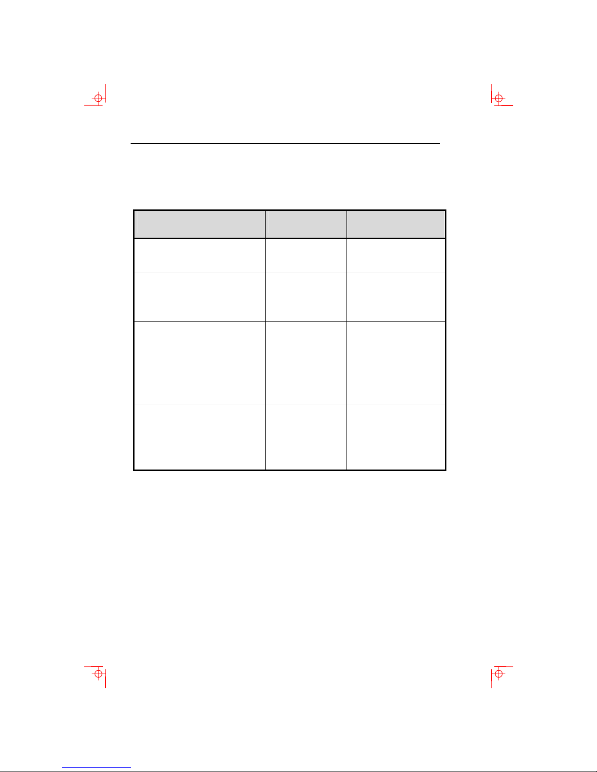
Obtain the following information before installing your VT510
video terminal. Write any changes to the default settings in the
column on the right.
Information Needed Obtain From…
The keyboard country
language that you have.
Terminal Emulation:
DEC VT, PCTerm, ADDS, SCO,
Bottom of the
keyboard
System Manager
TVI, WYSE
Communication Information:
Word size:
8 bits, 7 bits
Parity: none, even, odd, mark,
System Manager
space
Transmit speed:
9600
Printer Information:
Printer type:
DEC ANSI, IBM
ProPrinter, DEC + IBM
Printer serial speed:
4800
System Manager
The factory defaults are in boldface type.
Changes to Default
Setting
Page 9
Conventions
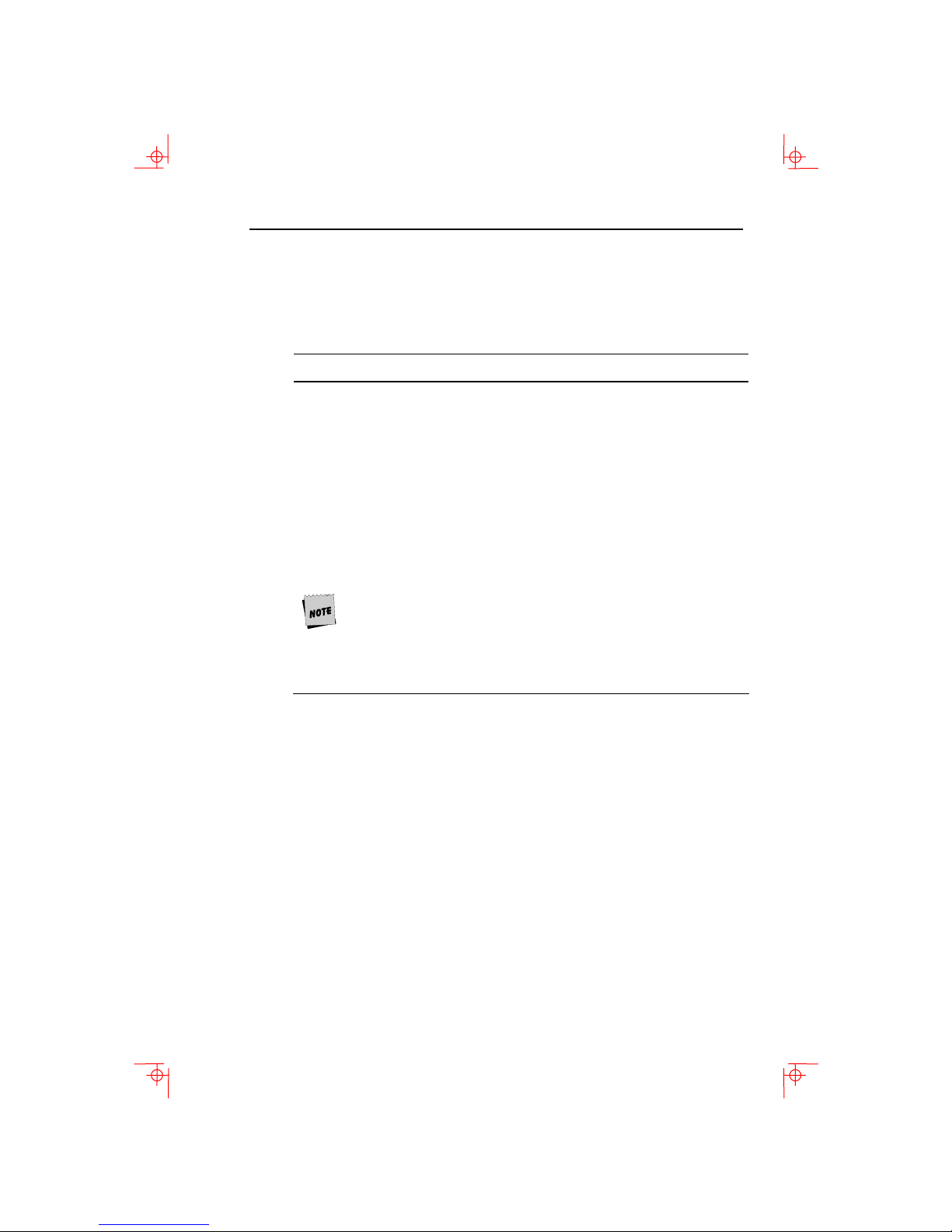
The following conventions are used in this document:
Convention Meaning
Shift+Tab Indicates two keys that you must press
in combination. Press and hold the first
key while you press the second key.
Shift–Enter Indicates two keys that you must press
in sequence. Press and release the first
key before you press the second key.
Caps Lock+Alt+F11 Indicates three keys that you must press
in combination, hold the first two down
while pressing the third.
terminal Describes the VT510 video terminal
Display Menu items are in boldface type.
Provides general information
Caution Provide information to prevent damage
to equipment.
Warning Provides information to prevent injury.
Conventions vii
Proper Setup and Use
Important Information: Certain recent scientific literature suggests
that poor posture, work habits, or office equipment setup may
cause injuries. Other literature suggests that there is no cause
and effect. Because the safety of our users is a great concern, it
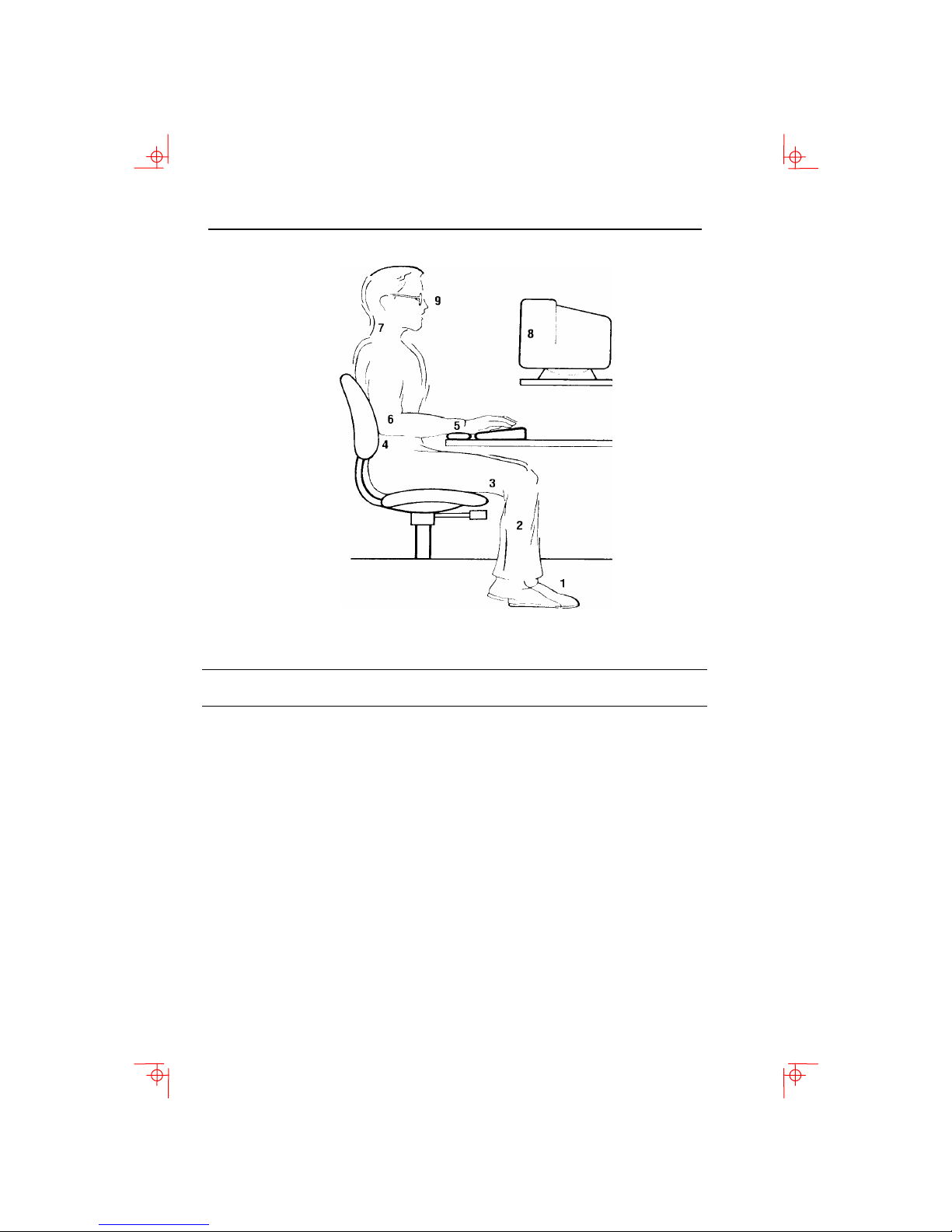
is important to take the precautions described in Table 1.
Page 10
viii Preface
Table 1 Recommendations for Proper Setup and Use
Adjust So that …
Chair
1 Feet are flat on the floor or footrest, if needed.
2 Legs are vertical forming a right angle to the floor.
3 Your weight is off your thighs and are in a horizontal
position. Keep the back of your knees away from the
seat so you do not compress the area behind them,
which could restrict the blood flow.
4 Your upper body is erect and your lower back is
supported with a backrest.
Keyboard
5 Your wrists are straight and do not flex more than
15°. They may be supported but should not rest on
sharp edges.
6 Upper arms are straight down at your sides, elbows
are close to your sides and support your arm weight.
Forearms are at a 70° to 90° angle.
Page 11

Proper Setup and Use ix
Table 2 (Cont.) Recommendations for Proper Setup and Use
Adjust So that …
Head
Terminal
Eyes
Work Breaks
Noise
Lighting
Temperature
Humidity
Ventilation
Space
Between
Terminals
7 Your neck is not strained. Your head should incline
downward, but no more than 15° to 20°.
8 Eye level and at the correct distance for proper
vision.
9 Avoid eye fatigue, which can be caused by glare,
image quality, uncomfortable furniture, eye height,
and uncorrected vision. If you cannot read the screen
at different distances, you may need special glasses.
Relax your eyes periodically by looking at distant
objects.
Take periodic work breaks. Morning, lunch, and
afternoon breaks meet most recommendations. Take
advantage of work breaks to move around and do
other movements.
Keep background noise at a minimum. Background
noise above 65 dBA is tiring. Sound-absorbing
materials, such as curtains, carpeting, and acoustic
tile, can help reduce background noise.
Avoid direct lighting or sunlight on the screen, which
causes glare and reflections. This terminal screen
has an antiglare treatment to reduce glare. Place
lighting behind or to the side of your work area, and
distribute the lighting evenly on your work area.
Adjust the brightness and the contrast controls as
needed.
20°C to 23°C (68°F to 74°F)
30% to 70%
Provide adequate air ventilation for equipment
operation and to avoid fatigue.
More than 70 cm (28 in.) enter to center, preferable
more than 152 cm (60 in.).
Page 12
x Preface
Warning: If you experience pain or discomfort during use of the
terminal, then take a substantial break and review the
instructions for posture and work habits. If the pain or
discomfort continues after resuming use of the terminal, then
discontinue use and report the condition to your job
supervisor or physician.
Page 13
chapter
1
1 Installation and Set-Up
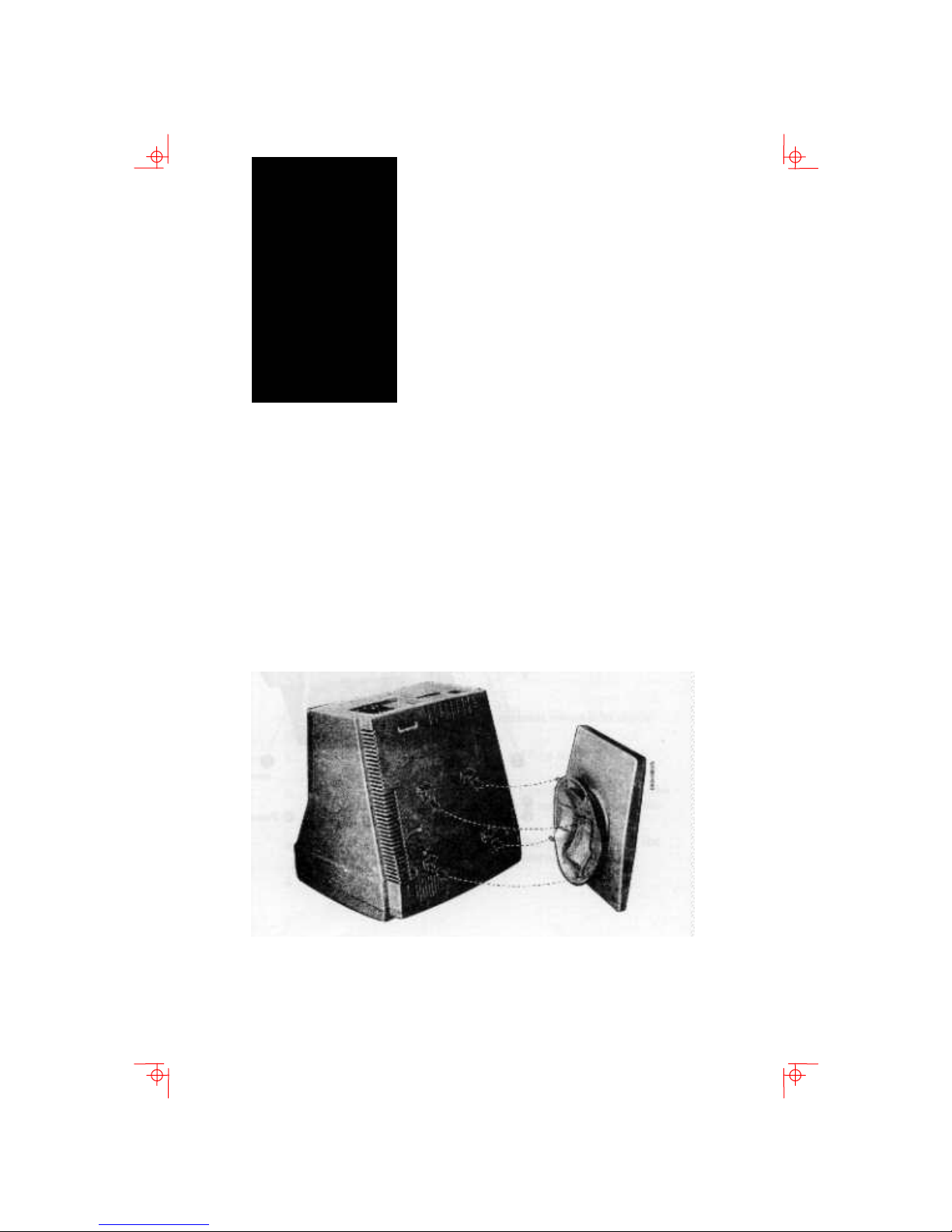
Install the tilt/swivel stand
1. Carefully set the terminal face down.
2. Insert the hooks on the stand into the slots at the bottom of
the terminal.
3. Slide the stand to the right until it is locked by the two tabs
at the bottom of the terminal. (To remove the stand, press
the two tabs.)
1-1
Page 14
1-2 Installation and Set-Up
Install your terminal
Connect the cables to the terminal
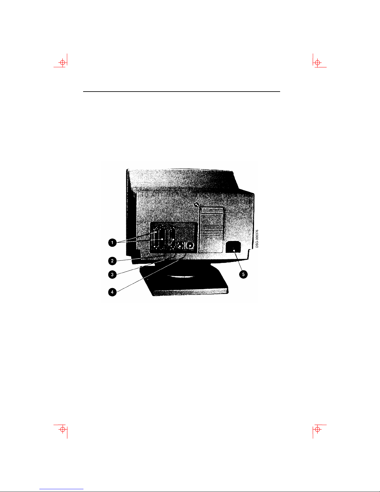
To install your terminal, connect the cable to the terminal as
shown.
Comm 1 (male or female), Parallel, Comm 2,
Keyboard, Power Cord.
Page 15
Install your terminal 1-3
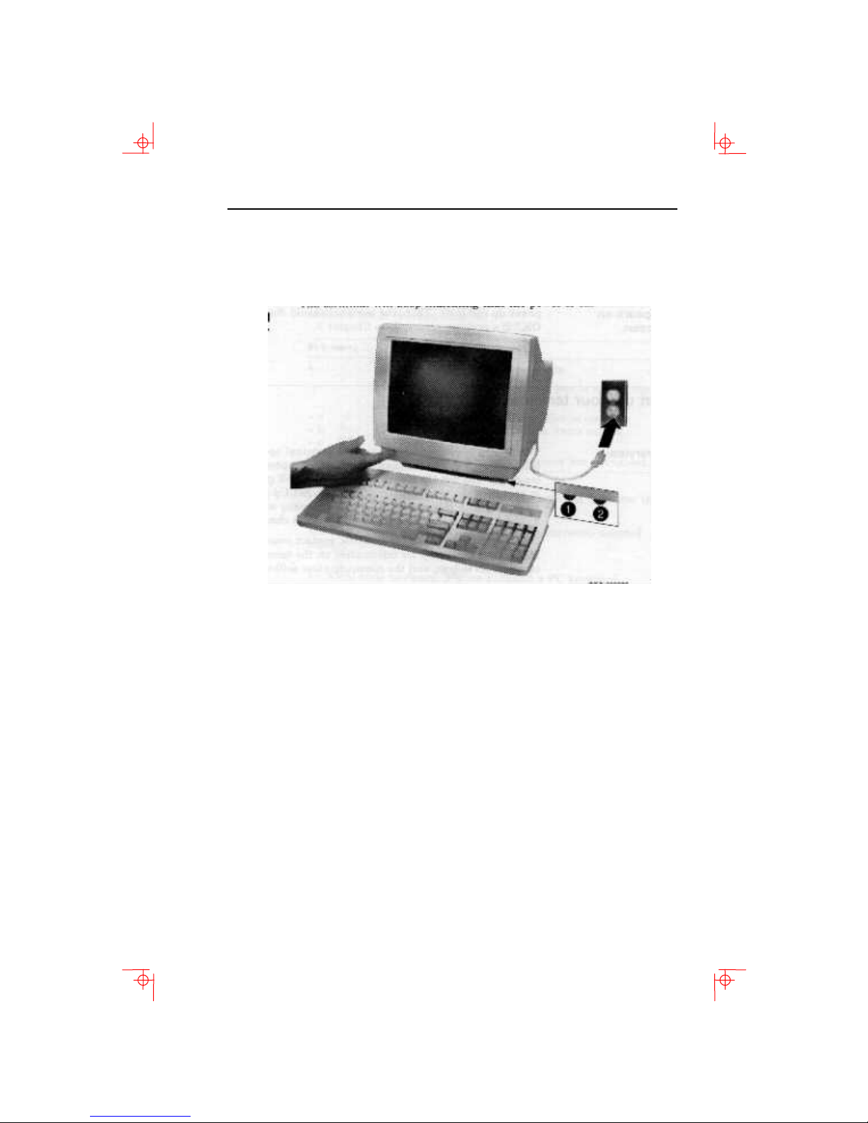
Plug in the power cord and push the power switch on
The terminal will beep indicating that the power is on.
Set the Brightness and Contrast controls
If necessary, set the brightness and contrast controls by doing
the following:
1. Set both controls to maximum by turning controls all the
way to the right.
2. Adjust the brightness control
the left until the background raster is not visible. This sets
the black level.
3. Adjust the Contrast control
left to set the white level for conformable viewing.
4. Repeat steps 2 and 3 as needed.
by turning the control to
by turning the control to the
“Selftest OK” appears on the screen
The terminal takes a few seconds to warm up and complete its
power up self-tests. Then, the terminal should display
OK.”
If a problem occurs, go to Chapter 3.
“Selftest
Page 16

1-4 Installation and Set-Up
Set up your terminal
Use Set-Up to examine or change the terminal operating
features, such as the transmit speed, receive speed, or the
language, The Set-Up menus in this section will get you started
in operating the terminal. Only the basic Set-Up feature is
performed with this procedure. There are many more Set-Up
features in the terminal that you may wish to change.
Before changing the Set-Up features, contact your System
Manager, if necessary, for information on the terminal type,
terminal ID to host, and the communication settings.
Printer operations are suspended upon entering Set-Up and are
resumed upon exiting Set-Up.
Entering Set-Up
To enter Set-Up, perform the following procedure:
On a … Press … Refer to …
ANSI-style
keyboard
PC keyboard
F3
Caps Lock+Print Screen or
Caps Lock+Sys Rq
Figure 1-1
Figure 1-2
Page 17

Keyboards 1-5
Moving within a Set-Up Menu
Use the arrow keys (, , , ) to move among the menus or
within a list or to select buttons.
In a menu … Indicates …
?
… A dialog box is available for you to specify
a
b
c
Press Enter, Return, Do, or Select to start the action or to choose
the currently highlighted feature.
A dimmed menu item does not apply to the currently selected
mode.
A pull-right menu is available.
more information.
The menu item with the filled-in circle is
enabled. Only one of these items can be
enabled at a time.
The menu item with the check box is
enabled.
Keyboards
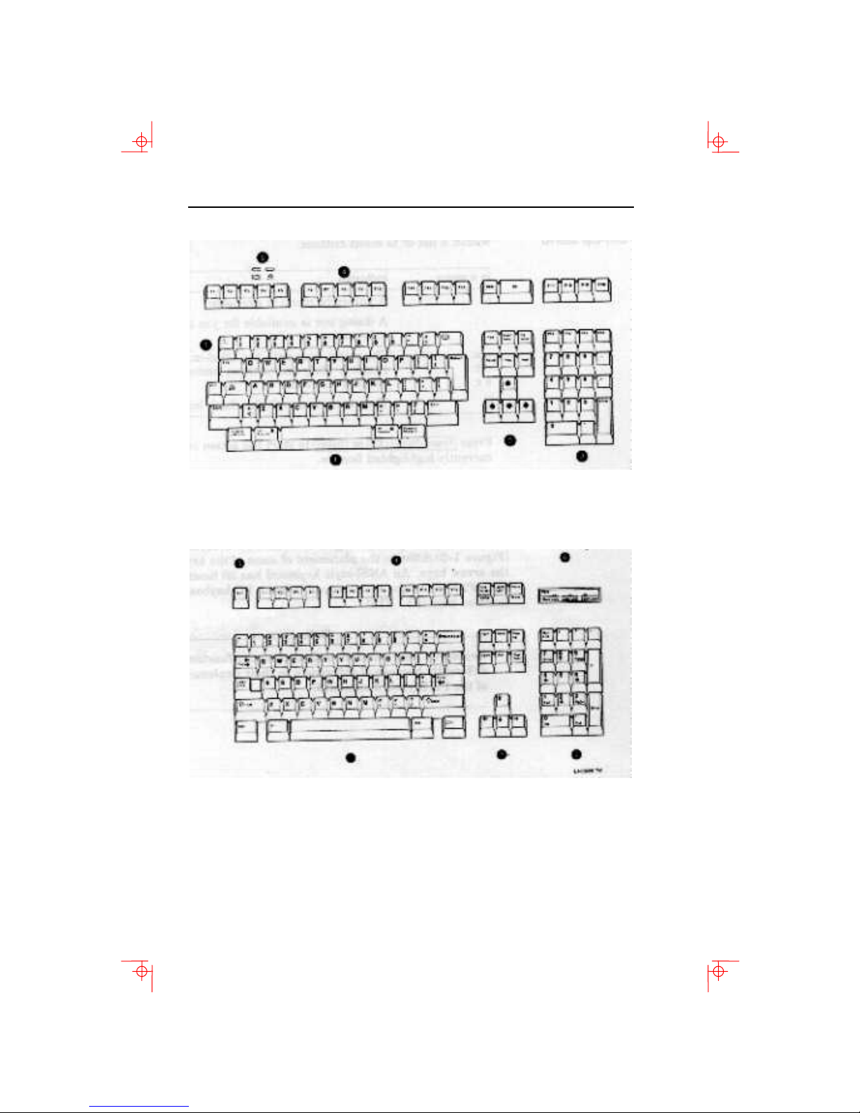
A DEC VT keyboard (Figure 1-1) and a PC keyboard (Figure 1-2)
differ in the placement of some of the keys, such as the arrow
keys. A DEC VT keyboard has 20 function keys (F1 – F20) above
the main keypad, while a PC keyboard has 12 function keys (F1
– F12).
Keyboards from other manufactures may function differently
because of differences in their implementation of the PC
keyboard standard.
Page 18
1-6 Installation and Set-Up
Figure 1-1 – DEC VT Keyboard Layout
Figure 1-2 – PC-Style Keyboard Layout
Main keypad, Editing keypad, Numeric keypad, Function
Escape key, Indicator lights.
keys,
Page 19
Select the Set-Up language 1-7
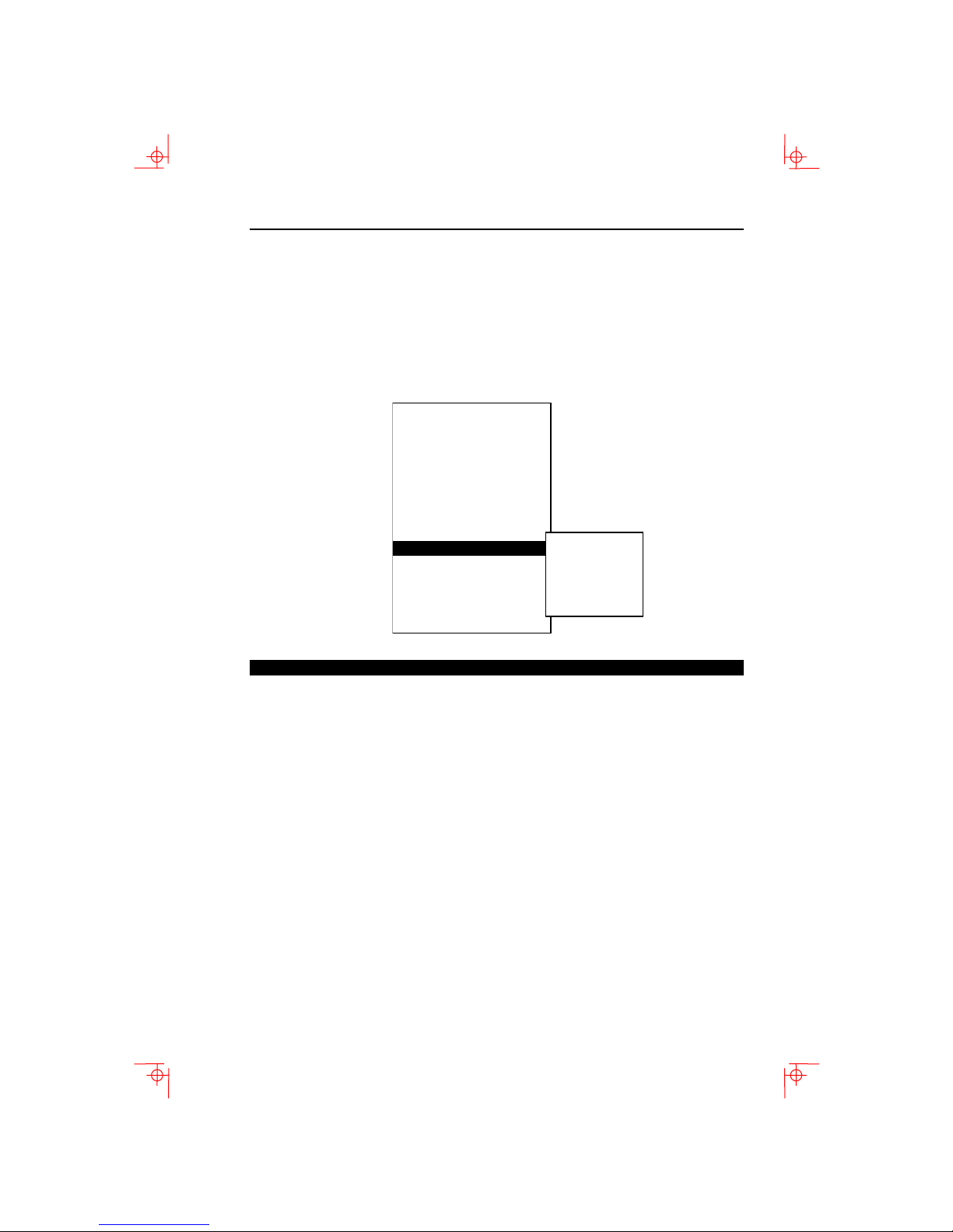
Select the Set-Up language
This language selection is for set up only and does not affect the
keyboard, the character set, or the printer settings. As you make
changes to some Set-Up parameters, the Set-Up summary line
will reflect those changes.
Actions
Display
Terminal type
ASCII emulation
Keyboard
Communication
Modem
Printer
Tabs ….
Set-Up language
--------------------------------- On-line
Save settings
Restore settings
Exit Set-Up
English
Franais
Deutsch
Espa²ol
Italiano
S1=comm1 9600N81 ISO Latin–1 North American VT510
Port selected, Transmit speed (9600), Parity (N), Word size (8),
Stop bits (1),
mode.
Character set, Keyboard language, Emulation
Page 20
1-8 Installation and Set-Up
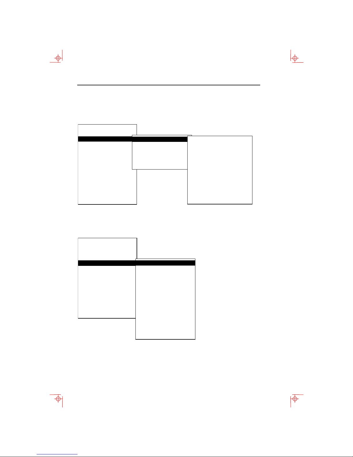
Select the emulation mode terminal type
Actions
Display
Terminal type
ASCII emulation
Keyboard
Communication
Modem
Printer
Tabs ….
Set-Up language
--------------------------------- On-line
Save settings
Restore settings
Exit Set-Up
Emulation mode
Terminal ID to host
VT default char set
PCTerm character set
7-bit NRCS characters
Transmit 7-bit controls
VT510 VT420 VT320 VT220
VT100
VT52
VT420 PCTerm
WYSE 160/60 Native
WYSE 160/60 PCTerm
WYSE 50+
WYSE 150/120
TVI 950
TVI 925
TVI 910+
ADDS A2
SCO console
Select the keyboard language
Actions
Display
Terminal type
ASCII emulation
Keyboard
Communication
Modem
Printer
Tabs ….
Set-Up language
--------------------------------- On-line
Save settings
Restore settings
Exit Set-Up
VT Keyboard language
PC Keyboard language
Define key …
Save key definitions
Recall key definitions
Lock key definitions
Caps lock function
Keyclick volume
Warning bell volume
Margin bell volume
Keyboard encoding
Auto repeat
Data processing keys
Application cursor keys
Application keypad mode
Page 21
Select the communication/printer port configuration 1-9
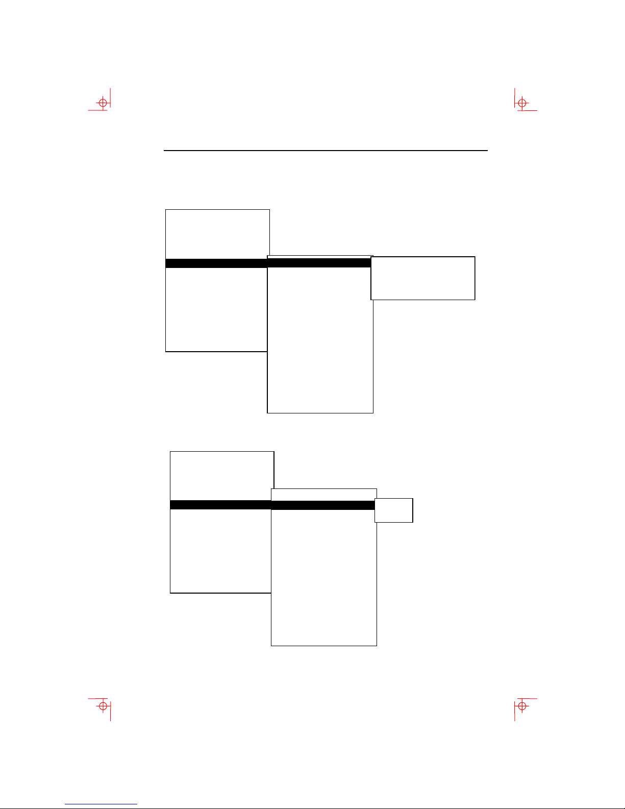
Select the communication/printer port configuration
Actions
Display
Terminal type
ASCII emulation
Keyboard
Communication
Modem
Printer
Tabs ….
Set-Up language
--------------------------------- On-line
Save settings
Restore settings
Exit Set-Up
Port select
Word size
Parity
Stop bits
Transmit speed
Receive speed
Transmit flow control
Receive flow control
Flow control threshold
Transmit rate limit
Fkey rate limit
Ignore Null character
Local echo
Half duplex
Auto answerback
Answerback message
Answerback canceled
Select the communication word size
Actions
Display
Terminal type
ASCII emulation
Keyboard
Communication
Modem
Printer
Tabs ….
Set-Up language
--------------------------------- On-line
Save settings
Restore settings
Exit Set-Up
Port select
Word size
Parity
Stop bits
Transmit speed
Receive speed
Transmit flow control
Receive flow control
Flow control threshold
Transmit rate limit
Fkey rate limit
Ignore Null character
Local echo
Half duplex
Auto answerback
Answerback message
Answerback canceled
S1=comm1 print=comm2
S1=comm1 print=parallel
S1=comm2 print=comm1
S1=comm2 print=parallel
8 bits
7 bits
Page 22
1-10 Installation and Set-Up
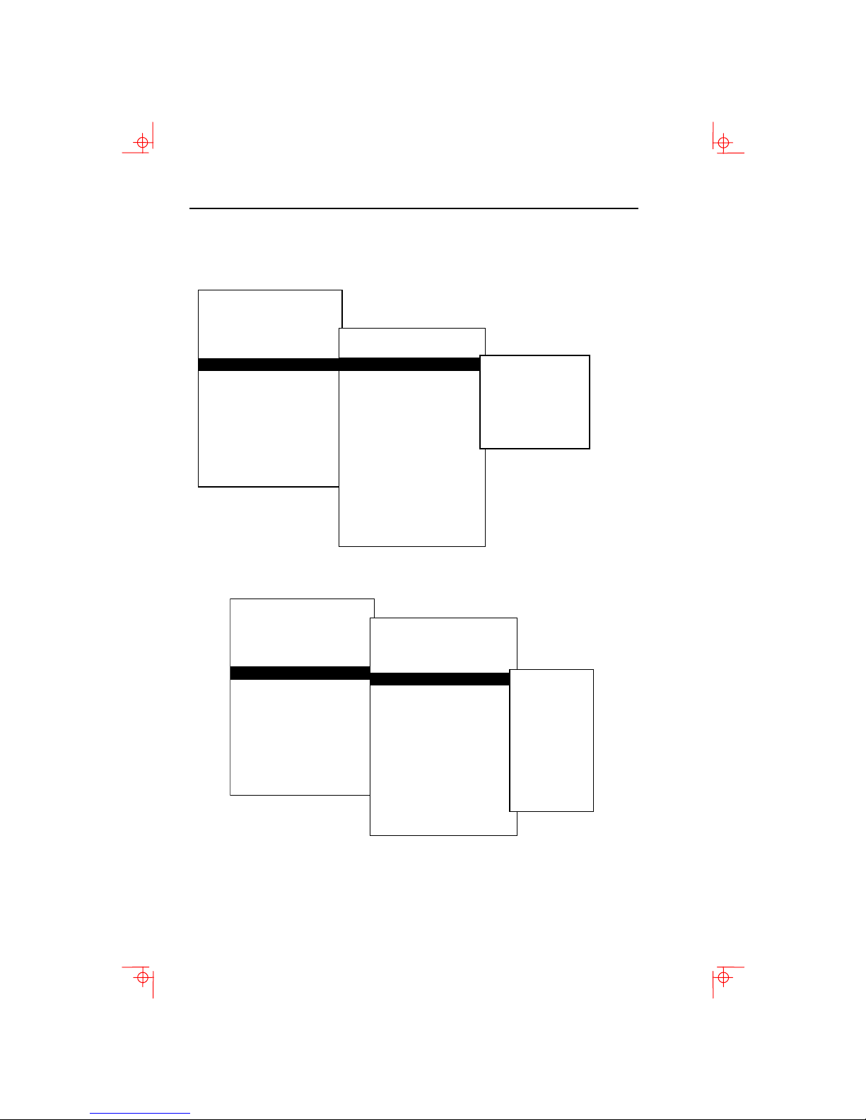
Select the communications parity
Actions
Display
Terminal type
ASCII emulation
Keyboard
Communication
Modem
Printer
Tabs ….
Set-Up language
--------------------------------- On-line
Save settings
Restore settings
Exit Set-Up
Port select
Word size
Parity
Stop bits
Transmit speed
Receive speed
Transmit flow control
Receive flow control
Flow control threshold
Transmit rate limit
Fkey rate limit
Ignore Null character
Local echo
Half duplex
Auto answerback
Answerback message
Answerback canceled
None
Even
Odd
Even, unchecked
Odd, unchecked
Mark
Space
Select the communication transmit speed
Actions
Display
Terminal type
ASCII emulation
Keyboard
Communication
Modem
Printer
Tabs ….
Set-Up language
--------------------------------- On-line
Save settings
Restore settings
Exit Set-Up
Port select
Word size
Parity
Stop bits
Transmit speed
Receive speed
Transmit flow control
Receive flow control
Flow control threshold
Transmit rate limit
Fkey rate limit
Ignore Null character
Local echo
Half duplex
Auto answerback
Answerback message
Answerback canceled
115.2K baud
76.8K baud
57.6K baud
38.4K baud
19.2K baud
9600 baud
4800 baud
2400 baud
1200 baud
600 baud
300 baud
Page 23
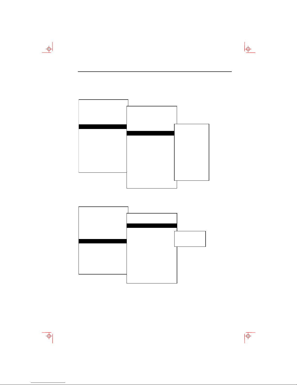
Select the communication receive speed 1-11
Select the communication receive speed
Actions
Display
Terminal type
ASCII emulation
Keyboard
Communication
Modem
Printer
Tabs ….
Set-Up language
--------------------------------- On-line
Save settings
Restore settings
Exit Set-Up
Port select
Word size
Parity
Stop bits
Transmit speed
Receive speed
Transmit flow control
Receive flow control
Flow control threshold
Transmit rate limit
Fkey rate limit
Ignore Null character
Local echo
Half duplex
Auto answerback
Answerback message
Answerback canceled
Select the printer type
Actions
Display
Terminal type
ASCII emulation
Keyboard
Communication
Modem
Printer
Tabs ….
Set-Up language
--------------------------------- On-line
Save settings
Restore settings
Exit Set-Up
Port select
Print mode
Printer type
DEC/ISO char sets
PC character sets
Print extent
Print terminator
------------------------------
Serial print speed
2-way communication
Transmit flow control
Receive flow control
Word size
Parity
Stop bits
Transmit speed
115.2K baud
76.8K baud
57.6K baud
38.4K baud
19.2.K baud
9600 baud
4800 baud
2400 baud
1200 baud
600 baud
300 baud
DEC ANSI
IBM Proprinter
DEC + IBM
Page 24
1-12 Installation and Set-Up
Save your settings
Select the Save Settings menu item, the press Enter or Return.
Caution: If you disable the Screen Saver feature, an image may
etch onto the screen, which may shorten the terminal’s useful
life.
Restore the settings
To recall the settings that you stored in memory using the Save
Setting
menu item, select the Restore Setting menu item and press
Enter or Return.
Restore factory defaults is a selection included in the Action menu.
Exit the Set-Up menu
To exit Set-Up, select the Exit Set-Up menu item or perform the
following procedure:
On a … Press … Refer to …
ANSI-style
keyboard
PC keyboard
F3
Caps Lock+Print Screen
Figure 1-1
Figure 1-2
Page 25
chapter
2
2 Desktop Features
Invoking Desktop Features
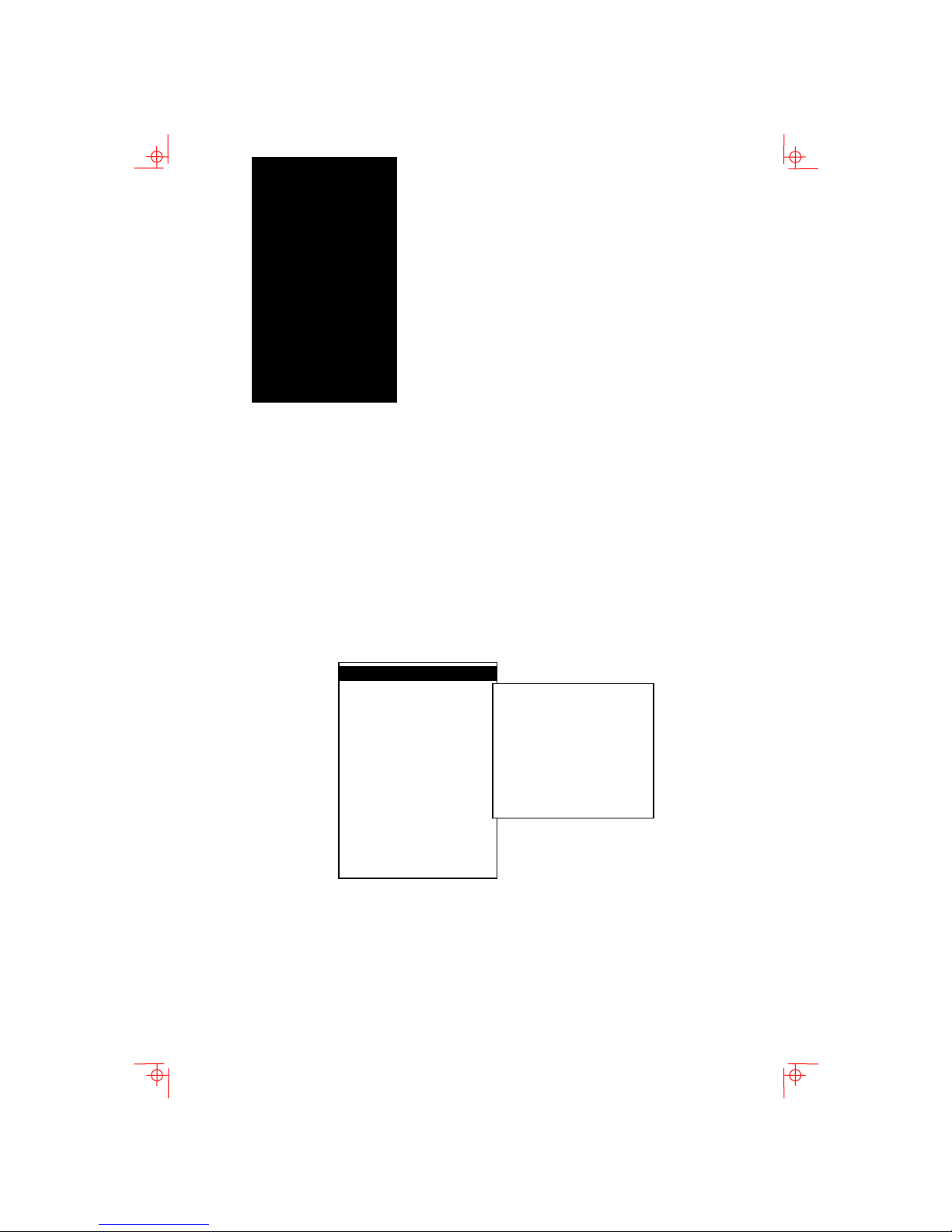
Overview
From the Actions menu, you can invoke the Clock, Calculator, Show
character sets
highlighted (displayed in reverse video), press
enable the feature.
, and Banner message features. When the feature is
Enter or Return to
Actions
Display Actions
Terminal type
ASCII emulation
Keyboard
Communication
Modem
Printer
Tabs ….
Set-Up language
--------------------------------- On-line
Save settings
Restore settings
Exit Set-Up
While these desktop features are enabled, other terminal
functions are disabled. Press
feature.
Clear display
Clear communications
Reset terminal
Restore factory defaults
------------------------------
Clock
Calculator
Show character sets
Banner message …
Ctrl+Z, F10, Exit, or Esc to exit the
2-1
Page 26

2-2 Desktop Features
Clock feature
You can enable the Clock feature without entering Set-Up by
pressing
mode.
The current time is displayed in the status line if this feature is
enabled. The format is HH:MM, followed by AM or PM if the 12hour format is selected. Use the following keys within the clock
features:
Key Function
or Tab
or Shift+Tab
or Move within a field.
Return or Enter
A or P
If the clock feature is enabled, then the alarm sounds for five
seconds or until a key is pressed. Each alarm message can be
up to 20 characters and will be displayed in the status line until
a key is pressed. If the hourly chime is enabled, then the
terminal will beep once every hour. In Set-Up, select the
settings
disabled when the terminal is turned off.
Caps Lock +Alt+F11 if you are not in an ASCII emulation
Go to next field.
Go to previous field.
If desired, check the 24-hour
format box. For example, before
entering 13:00, enable
format
.
For 12-hour format, set the time
to morning by pressing
afternoon.
menu item to save the time format. The clock feature is
24-hour
A or P for
Save
Page 27

Invoking Desktop Features 2-3
Calculator feature
You can enable the Calculator feature without entering Set-Up by
pressing
mode.
In addition to the numbers on the numeric keypad, you use the
following keys within the calculator:
Key Function
H, O, or D Select hexadecimal H, octal O, or
Arrow keys Move the position of the
Shift
Alt
C/E
STO
RCL
Shift–Enter
All calculator math operations have equal priority except 1/
2
. If a result is wider than the display, then a rounded number will be
χ
displayed. The non-rounded result will continue to be used in
subsequent calculations. The decimal point cannot be used with the
hexadecimal mode.
Caps Lock +Alt+F12 if you are not in an ASCII emulation
decimal
D format.
calculator on the screen.
Change the keypad display to
allow selecting
and
Insert Results.
STO, RCL, 1/x, X2,
Change the keypad display to
hexadecimal and allow selecting
keys
A through F o the numeric
keypad.
Clear the entry.
Store the number in the display
into memory.
Recall the number from memory
and place it in the display.
Insert the result at the current
cursor position after exiting the
calculator feature.
χ and
Page 28

2-4 Desktop Features
Show Character Sets feature
You can enable the Show character sets desktop feature without
entering Set-Up by pressing
an ASCII emulation mode. When the character set is displayed,
you can use the following keys with this feature:
Key Function
Next or Prev
Page Up
Shift–L
Shift–T
Shift–Enter
or Page Down
Caps Lock +Alt+F10 if you are not in
Look through the available
character sets.
Display the line drawing character
set if you are using a VT character
set.
Display the technical character
set.
For the current character set,
insert the highlighted character
into text at the current cursor
position, if you are using a VT
character set.
Banner message
From the Actions menu, select Banner message …
1. Press Return or Enter to display a dialog box.
2. Enter our banner message.
3. Press the to select the
4. Press Return or
Enter to Return to the Set-Up menu.
OK button.
Page 29

chapter
3
3 Maintenance and
Troubleshooting
Cleaning your Video Terminal
Cleaning the Screen
Before cleaning the screen, set the terminal power switch to the
off position and wait 20 seconds to let the static electricity
dissipate. Clean the screen with a video screen cleaner.
Cleaning the Keyboard
If needed, wipe the keys with a soft cloth. Do not allow moisture
to get under the keys.
Troubleshooting
Identifying and Correcting Problems
The following can be sources of problems:
Communications cables
Host system
Nearby power or electrical sources
3-1
Page 30

3-2 Maintenance and Troubleshooting
Troubleshooting Table
Use Table 3-1 to identify and correct any problem areas.
Table 3-1 Identifying and correcting problems
Symptom Possible Cause Suggestion Solution
Cursor or “Selftest
OK” does not
display
Screen is blank,
but cursor is
blinking.
Brightness or
Contrast control
is set too low.
Power cord is
not connected.
There is no
power.
The terminal is
faulty.
Screen saver is
active.
Signal cable is
not connected.
Communications
port is not set
properly.
Communication
speed may be
set incorrectly.
The host system
may be faulty.
Increase the brightness and contrast
control setting under the front of the
terminal.
Connect the power cord to the power
source and the terminal. Push the
power switch in.
Use a function outlet.
Set the power switch to the off position
and contact the service representative.
Press any key.
Reconnect the cable.
From the
choose
setting for the cable connections.
Check the communication transmit
speed, receive speed, and parity with
you system manager; then match them
to the Set-Up settings.
Contact your system administrator.
Communication menu item,
Port select and check the
Video is off center. The Earth’s
magnetic field at
your location
may be causing
the display to
shift.
From the
Screen alignment.
Display menu item, choose
Page 31
Troubleshooting 3-3
Table 3-1 (Cont.) Identifying and correcting problems
Symptom Possible Cause Suggestion Solution
Video display has
moving dots and
distorted lines.
The display rolls
or flickers.
The printer will not
print.
There is
electromagnetic
interference.
Refresh rate is
too low.
The terminal is
faulty.
The printer
power is not on.
The printer
cables are not
connected.
Communication
port is not set
correctly.
If you have a
serial printer, its
speed may be
set incorrectly.
Move and electromechanical device,
such as a fan or a motor, away form the
terminal or move the terminal.
CAUTION: Before moving the system, turn
the power off and wait 20 seconds to let
the static electricity dissipate.
From the Display menu item, choose
Refresh rate and select 72 Hz.
Set the power switch to the off position
and contact the service representative.
Turn on the power to the printer.
Check the cables.
From the
choose
Communication menu item,
Port select and match the
setting to the connections on the
terminal.
From the
Printer menu item, choose
Serial print speed and match the setting
to the one in your printer manual.
Modifier keys
remain in effect
after released.
Accessibility aid
enabled.
Check keyboard indicator line for icon.
This feature is enabled by pressing any
key modifier key five times. To disable,
press and hold a modifier key and then
press another key.
Page 32
3-4 Maintenance and Troubleshooting
Disposing of your Terminal
Warning: If you need to dispose of your terminal, ask a
qualified service representative for the proper disposal
procedures. Improper disposal could result in personal injury.
Installing the ROM Cartridge
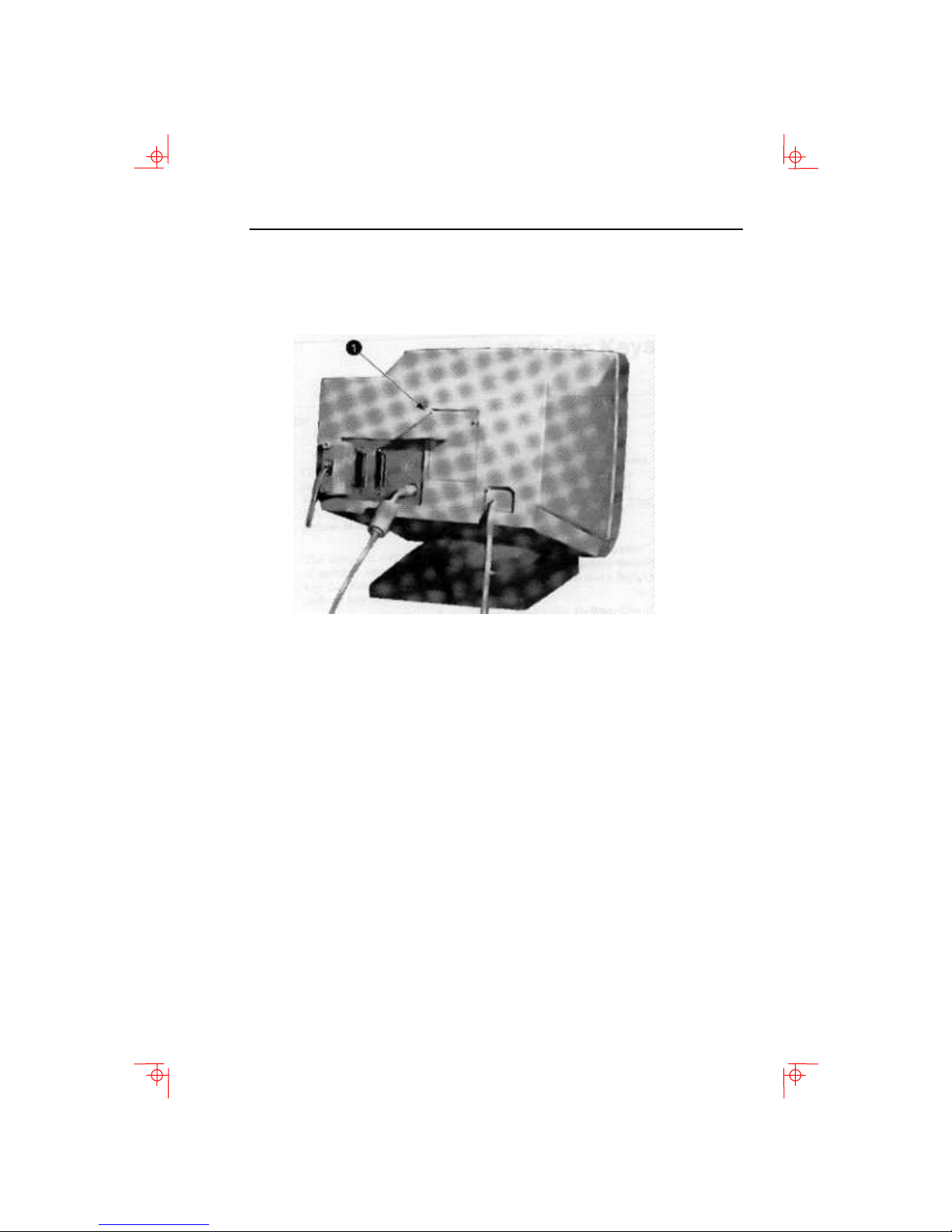
The terminal can accommodate an optional ROM cartridge at the
back of the terminal. This ROM cartridge will completely replace
the factory-installed software within the terminal for new
software versions or special applications.
When an option ROM is not used, the ROM cartridge holder is
empty with a cover over it.
Installing and Removing the ROM Cartridge
To install a ROM cartridge:
1. Set the power switch to the off position.
2. Remove the blank cover by lifting the cover from the bottom
and gently pulling it straight back.
3. Plug in a ROM cartridge with its attached cover
the cover.
, and close
Page 33
Installing the ROM Cartridge 3-5
If you are having the terminal serviced, then remove and save the ROM
cartridge.
To remove a ROM cartridge, lift its cover from the
bottom and gently pull it straight back.
Page 34

Page 35

chapter
4
4 Defining Keys
Define Key Editor
The VT510 provides a powerful Define Key Editor that allows you
to modify the function of keys on your keyboard. Since VT510
keystrokes can perform many different functions, it will take
some practice to understand how the keys work. This section is
an introduction to customizing your keyboard.
Moving Standard Functions
The simplest way to re-program a key is to copy the behavior of
another key. This method allows you to move factory default key
functions to any position on the keyboard. To move factory
default key functions:
1. From the Keyboard menu item, select the
function, and the
2. Press the key for which you want to assign a new behavior.
3. Press the key to highlight the “Copy of key default” radio
button (• Copy of key default) and press
4. Press the key whose factory default behavior is what you
want your defined key to do.
5. Press the key to highlight the OK or Apply pushbutton
and press Enter.
Define Key Editor menu will appear.
Define key …
Enter.
4-1
Page 36

4-2 Defining Keys
Customization
If you want to program a key to behave differently than one of
the factory defined keys, then you will need to know about the
following VT510 key categories:
Function: Keys used to transmit function key sequences
or to perform local terminal functions such as
the arrow keys (, , , ), and
keys, or the
Alphanumeric: Keys used to transmit alphanumeric
characters.
Set-Up key.
Shift modifier
Modifier Keys
Modifier keys vary from within the function and alphanumeric
categories. A modifier key is a key that modifies the behavior of
other keys when it is pressed and held down. For example,
pressing an alphanumeric key in combination with the
modified key will normally send the shifted or uppercase
characters for that key.
Modifier keys are treated as a special kind of local terminal
function. The VT510 function modifier keys are:
Alt. VT510 alphanumeric keys can also be modified by pressing
Group Shift (Alt Gr on enhanced PC keyboards) and Alt+Shift (Shift-2).
Modifier keys themselves cannot normally be modified by other
keys. A key assigned to act as the
cannot transmit a functions sequence when pressed in
combination with the
makes all assignable combinations of that key act as a modifier.
Alt key. Defining a key as a modifier key
Shift modifier, for example,
Shift, Ctrl, and
Shift
Creating a New Function
To define a new function key:
1. From the
function, and the
2. Press the key for which you want to assign a new behavior.
3. Press the and keys to highlight the “Function” radio
button (• Function) and press Enter.
4. Press the and keys to highlight the modifier
combination that you want to define (unshifted, shifted,
control, and so on) and press
Keyboard menu item, select the Define key…
Define key editor menu will appear.
Enter.
Page 37

Define Key Editor 4-3
5. Press the key to move to the “Select function” scroll box.
Press the and keys to highlight the desired keystroke
function from the list and press
Enter.
6. Press the key to return to the modifier selection.
7. Repeat steps 4 through 6 to define other modifier
combinations as desired.
8. Use the arrow keys (, , , ) to highlight the OK or
Apply pushbutton and press
Enter.
Correcting a Mistake
If you make a mistake or want to start over, select the Cancel
pushbutton or select the
Exit Set-Up menu item. Your changes
will not be recognized until you select the OK or Apply
pushbutton. To save your key definitions so they will be
available the next time you turn on the system power, select the
Save key definitions menu item for the Keyboard menu.
Examples of Uses
Examples of when to create new functions include:
To change the ⌫ key to delete when unshifted and to
backspace when shifted
To disable the Compose, Break, or set-Up key by assigning
them to have no function
The Define Key editor can be very powerful if you take the time
to learn how to use it. No matter how you define the keys, you
can always enter Set-Up by pressing
Additionally, you can always restore the factory default settings
by invoking the
Actions menu items.
F3 after powering on.
See the VT510 Video Terminal Programmer Information manual
to redefine alphanumeric keys or keyboard layouts.
appendix
Page 38

5-4 Specifications
A
5 Specifications
Video Terminal
The following are the specifications for the VT510 video terminal.
Dimensions
Height 32 cm (12.6 in)
Width 31.5 cm (12.4 in)
Depth 33 cm (13 in)
Weight 7.9 kg (17.4 Ib)
Tilt Range 25° (5° forward, 20° backward)
Swivel Range
Display
Cathode ray tube
(CRT)
Overscan 60 Hz – 16 x 10 font; 72 Hz – 13 x 10 font
Area 800 x 432 pixels with 88 DPI density
Usable area 17 cm (6.7 in) x 23 cm (9 in); 1:1.4
No. of lines 25, 42, or 53 data lines
Page size Selectable 24, 25, 36, 42, 48, 50. and 72
Operating Systems
Supported
± 90° (left and right)
35 cm (14 in) diagonal antiglare flatprofile screen
aspect ratio
lines (emulation dependent)
UNIX, MDOS, OpenVMS, OSF, ULTRIX,
VMS, or any other that supports ASCII or
ANSI protocols.
Page 39

Video Terminal 5-5
Terminal Emulations ANSI, PCTerm, and ASCII emulations:
VT, WYSE. TVI, ADDS, or SCO console.
Character Set Support Multiple languages using ISO and IBM
code pages; Set-Up selectable in five
languages
Productivity Features Local copy and paste
Time-of-day clock—sound alarms and
display messages
Desktop calculator—insert result into text
Show character sets—insert character
into text.
ROM cartridge support 4-Mbit (512 K byte) customer- installable
ROM cartridge at back of system unit
that completely replaces the factory
installed ROM code for new versions of
the terminal’s firmware
Electrical Requirements
AC input voltage
120 Vac only; or 110, 120, 220, 330,
240 auto-sensing (product variant)
single phase, 3-wire
Line frequency
Power consumption
Operating Temperature
Humidity
47 Hz to 63 Hz
40 watts maximum
10°C to 40°C (50°F to 104°F)
10% to 90% relative humidity
Maximum wet bulb = 28°C Minimum
dew point = 2°C (noncondensing)
Keyboard The following are the specifications for
the keyboard.
Keyboard style
LK411/LK412 for ANSI/ANSI WPS style
layout; PCXAL for enhanced PC 101/102
style layout; available for most European
languages.
Protocol
Connector
Keyboard keys
IBM enhanced PS/2-compatible
PS/2-style, 6-pin mini DIN
All keys are programmable for single
characters, character sequences, or
local functions.
Nonvolatile memory 768K bytes memory
Page 40

5-6 Specifications
Cables
BC19M-10 3 m (10 ft.) 25-pin D-sub m to
Communication/Printer
Ports
Serial Bidirectional serial communication/
Parallel Centronics (25-pin D-sub f) parallel
User-defined key maximum length =
255 bytes
The following are the specifications for the cables.
Order Number Length Connectors
*
EIA-232 Serial Communications/Printer Cables
BC22E-10 3 m (10 ft.) 25-pin D-sub f to
BC22E-25 7.6 m (25 ft.) 25-pin D-sub m
BC22D-xx xx
†
25-pin D-sub f to
25-pin D-sub f
EIA-422 Communications Cables
BC16E-10 3 m (10 ft.) 6-pin MMJ to 6-pin
BC16E-25 7.6 m (25 ft.) MMJ
Parallel Printer Cables
25-pin D-sub m
*
EIA-232 maximum cable length is 15.3 m (50 ft.); EIA-423
maximum cable length is 305 m (1000 ft).
†
xx = length in feet (10, 25, 50)
printer ports with full modem support at
300 to 115.2K baud:
EIA 423
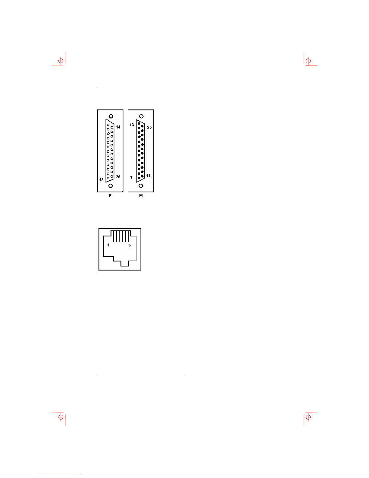
Comm1 (Figure A-1): Two 25-pin D-sub
m/f (use one or the other)
EIA 232
Comm2 (Figure A-2): 6-pin MMJ
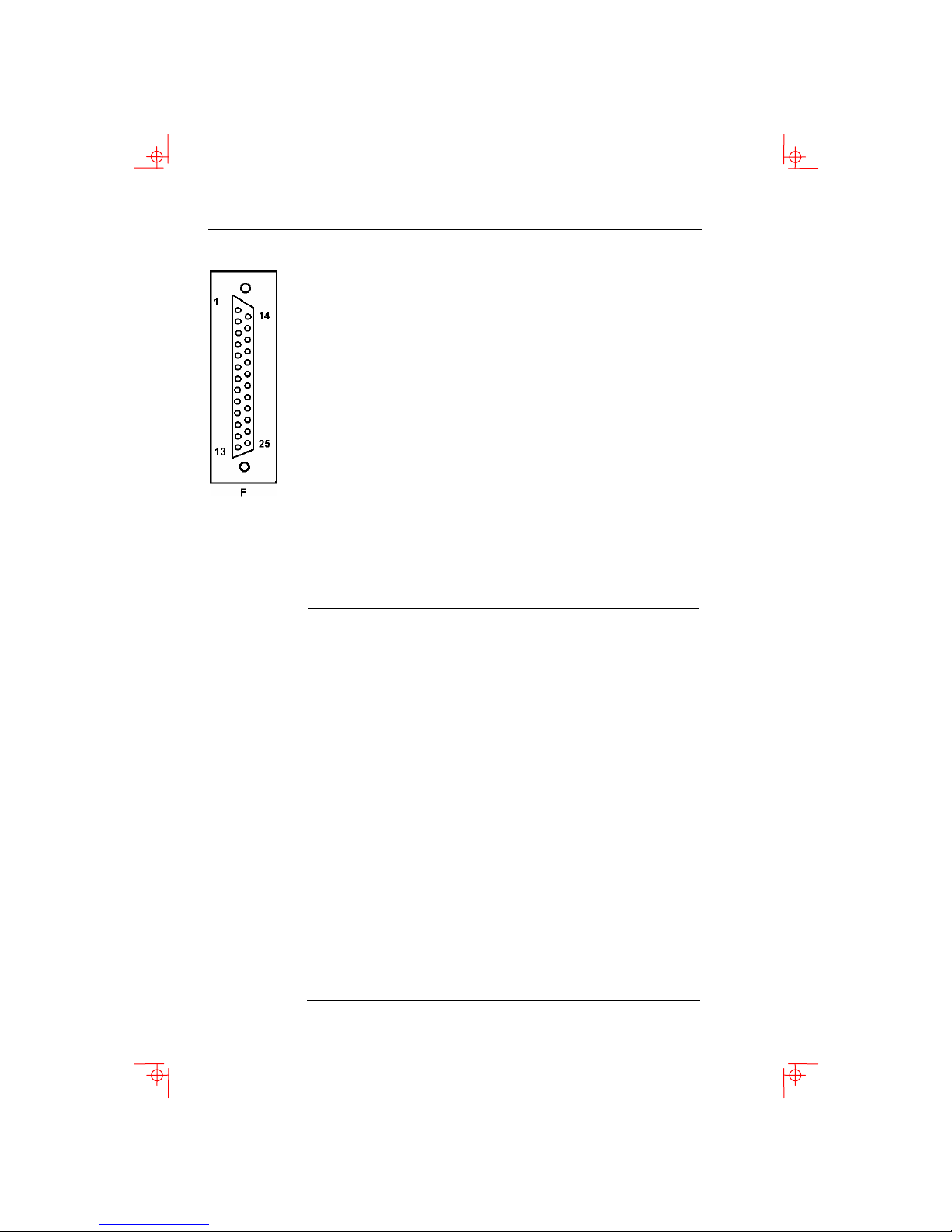
printer connector (Figure A-3).
m = male; f = female
Page 41
Video Terminal 5-7
1 GND/NC
1
1
2 TXD
3 RXD
4 RTS
5 CTS
6 DSR
7 SIG GND
8 CD
12 SI
20 DTR
23 SPD SEL
9-11, 13-19, 21, 22, 24,
25 NC
CCITT/EIA/DIN
103/BA/DI
104/BB/D2
105/CA/S2
106/CB/M2
107/CC/M1
102/AB/E2
109/CF/M5
112/CI
108.2/CD/S1.2
111/CH/S4
Figure A–1 Comm1—Serial Communication/Printer Ports
1 DTR
2 TXD +
3 TXD –
4 RXD –
5 RXD +
6 DSR
l
Figure A–2 Comm2—MMJ Port
1
In North America, pin 1 is open; in international units, pin 1 is ground.
NC = Not connected.
Page 42
5-8 Specifications
1 STROBE L
2 DAT<0>
3 DAT<1>
4 DAT<2>
5 DAT<3>
6 DAT<4>
7 DAT<5>
8 DAT<6>
9 DAT<7>
10 ACKNLG L
11 BUSY
12 PE
13 SLOT
14 AUTO FEED XT L
15 ERROR L
16 INIT L
17 SLCT IN L
18–25 GND
Figure A–3 — Parallel Printer Port
Power Cords
The following are the specifications for the power cords.
Order Number Country Amp Length
BN19H-2E Argentina, Australia, New 15A 3.5 m
Zealand
BN19W-2E Central Europe 15A 2.5 m
BN19W-2E Brazil, Chile, Columbia, 15A 3.5 m
Paraguay, Uruguay
BN19P-2E Canada, U.S. 15A 1.9 m
BN19P-03 3.0 M
BN19K-2E Denmark 15A 2.5 m
BN19A-2E Ireland, United Kingdom 15A 2.5 m
BN19S-2E India, South Africa 15A 2.5 m
BN18L-2E Israel 15A 2.5 m
BN19M-2E Italy 15A 2.5 m
BN24T-2E Switzerland 15A 2.5 m
BN26J-1K or Bolivia, Colombia, Ecuador,
(17-00083-xx)
*
xx = -38 = 125V, 13A
*
Mexico, Venezuela
*
1.9 m
-39 = 125V, 15A
-40 = 250V, 10A
-41 = 250V, 10A
Page 43
Acoustic Noise
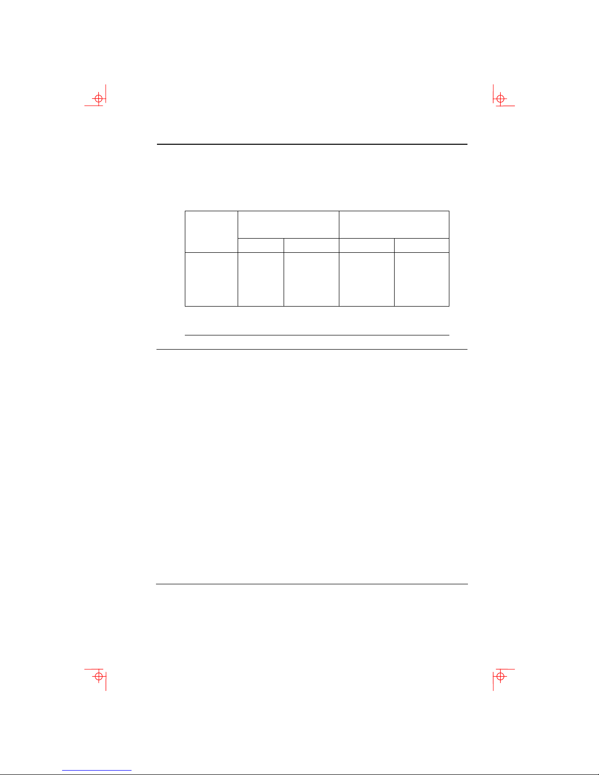
Preliminary declared values per ISO 9296 and ISO 7779:
Acoustic Noise 5-9
Sound Power Level
,
B
L
Idle
<3.9
NA
NA
NA
w A d
Operate
<3.9
6.0
5.3
5.6
Product
1
VT510
PCXAL
PC7XL
LK411
1
Current values for specific configurations are available from
Boundless representatives (1 B = 10dBA.)
2
Operator position.
Sound Pressure Level
L
,
dBA
p A m
Idle
Operate
<22
NA
NA
NA
2
<22
51
47
52
Agency Type Standard Subject
CSA Safety CSA 22.2 #950
M1989
CSA 22.1
Safety of Information
Technology Equipment
Including Electrical Business
Equipment (Canada)
Canadian electrical code
CISPR-22 EMI/RFI CISPR-22 Class A Electromagnetic
compatibility
EIA Telcom EIA 423
Serial communications
EIA 232-E
DOC Canada EMI/RFI CSA 108.8 North American Class A
version
FCC EMI/RFI FCC part 15
Electromagnetic compatibility
Class B
Australia PPT
German PPT
Telecom CCITT V.24 and
V.28
Serial communications
Japan PPT
Sweden PPT
Australia Safety AS3260 Australia product safety
Page 44

5-10 Specifications
Agency Type Standard Subject
TUV Safety EN60950 (2nd ed,
1988)
EN60950 (Amd 1 &
2, 1990)
IEC950( 2nd ed,
1991)
Safety of Information
Technology Equipment
Including Electrical Business
Equipment
GS-Marl (Geprüfte Sicherheit)
German X-Ray Act
RöV §5(2)
EMKO-TSE (74SEC) 203/92
SS 436 14 90, MPR
II
TUV Ergonomic
ISO/DIS 9241-3 VDT Ergonomic
Requirements
UL Safety UL 544 (2nd ed) Standard for Medical and
Dental Equipment
UL 1950 (1st ed) Safety of Information
Technology Equipment
Including Electrical Business
Equipment
NFPA 70 U.S. National Fire Protection
Agency - National Electrical
Code
VDE EMI/RFI Vfg 243/1991
Radio Protection Mark
EN55022 class B
VCCI
EMI/RFI Class 1 Electromagnetic compatibility
(Japan)
Page 45
Flame Retardants 5-11
In addition to the standard listed
previously, the VT510 low-emissions
video terminal complies with the
following standards:
Agency
NBOSH EMI/RFI MPR-2 1990:8 Swedish National Council for
Type Standard Subject
Metrology and Testing
Display Units
EMI/RFI SS 436 14 90 Swedish standard for low
emissions
Flame Retardants
The thermoplastic enclosures do not contain polybrominated
diphenylether (PBDE) as a flame retardant additive; therefore,
they do not emit toxic dibenzofuran and dibenzodioxin gases.
PVC
The plastic enclosures are not made of rigid PVC. The material
has a non-halogenated, flame-retardant system and is cadmium
free.
Asbestos
Asbestos is not used in this product or in its manufacturing
process.
Ozone Depleting Substance
The VT510 is in full compliance with the labeling requirements
in the U.S. Clean Air Act Amendments of 1990. It does not
contain, nor is it manufactured with a Class 1 ODS, as defined
in Title VI Section 611 of this act.
Page 46

Page 47

appendix
B
6 Keyboard Function Keys
User Definable Keys
All keyboard keys are programmable by selecting the Define key
function
programmed to send single characters or character sequences,
or to invoke a local function, such as Print Screen.
The function keys have the following key levels: Unshifted,
Shifted, Control, Shift Control, Alt, Alt-Shift, Alt-Control, and
Alt-Shift-Control.
from the Keyboard menu item in Set-Up. They can be
Local Functions
The keys used to perform local terminal functions differ between
the VT keyboard, PC keyboard, and the mode selection. Table B-l
shows the corresponding keys for the default local functions and
their function number. This number is used in the DECPAK’s
host sequence or DECPAK's alternate function to specify a
change to that Local Function key. Table B-2 lists other available
local functions.
6-1
Page 48

6-2 Keyboard Function Keys
Table B-1 Local Functions
Function
Number
0 no function
1 Hold F1 Lock+F1 F1 Scroll Lock
2 Print F2 Lock+F2 F2 Print Screen
3 Set-Up F3 Lock+F3 F3 Lock+Print Screen
5 Break F5 Lock+F5 F5 Lock Pause
7 Hard Reset Ctrl+F3 Lock+Ctrl+F3 Ctrl+F3 Ctrl+Lock+
8 Toggle Autoprint Ctrl+F2 Lock+Ctrl+F2 Ctrl+F2 Ctrl+Print Screen
9 Disconnect Shift+F5 Lock+Shift+F5 Shift+F5 Shift+Lock+Pause
10 Send Answerback Ctrl+F5 Lock+Ctrl+F5 Ctrl +F5 Ctrl+Lock+Pause
11 Print Composed
20 Pan Up Ctrl+ X Ctrl+ Ctrl+ X
21 Pan Down Ctrl+ X Ctrl+ Ctrl+
24 Pan Prev Page Ctrl+Prev X Ctrl+Page
25 Pan Next Page Ctrl+Next X Ctrl+Page
30 Copy & Paste
Function
Main Display
Mode
VT
Keyboard
Shift+F2 X
F1 (hold
down)
SCO
Console
PC
Keyboard
VT-Style
PC
Keyboard
PC-Style
Lock+Sys Rq
Alt+Print Screen
Print Screen
1
Shift+F2 Shift+Print Screen X
Ctrl+Page Up
Up
Ctrl+Page Down
Down
Caps Lock+F1 F1 Scroll Lock
PC
Keyboard
SCO
1
X means the function is not available in the default SCO state. If there is no
“X” in the SCO Console column, then this means that the key sequence is the
same as the VT Keyboard column. If there is no “X” in the PC Keyboard SCO
column, then this means that the key sequence is the same as the PC
Keyboard PC-Style column.
Lock means the Lock key, Caps Lock key, or key with lock icon.
Page 49

Local Functions 6-3
Table B-1 (Cont.) Local Functions
Function
Number
31 C&P Cursor Left
32 C&P Cursor
33 C&P Cursor UP
34 C&P Cursor Right
35 C&P Start
36 C&P Copy Remove End End
37 C&P Paste Insert Here Insert Insert
38
41 Shift Modifier Left or right
42 Control Modifier Ctrl Left or right
43 Alt Function
44 Start Compose Left or right
45* Group Shift
Function
Down
Selection
±
x
C&P
Left-to-Right
Modifier
Modifier
VT
Keyboard
SCO
Console
PC
Keyboard
VT-Style
PC
Keyboard
PC-Style
PC
Keyboard
SCO
Select Home Home
Select Home Home
Shift
Left or right
Shift
Left or right Shift
Left or right Ctrl
Ctrl
Left or right Alt Left or right
Left or right Alt
Alt
Left Alt+Space
Compose
Group Shift Alt+Gr Alt+Gr
±
means the function switches alternately between on and off.
C&P means Copy and Paste.
Page 50

6-4 Keyboard Function Keys
Table B-1 (Cont.) Local Functions
Function
Number
46† Shift2 Modifier Alt Shift
47 Primary KB
48 Secondary KB
49
51
52
53
54 Extend Kbd
61 Screen saver
62 Calculator Lock+Alt+F12 Lock+Alt+
63 Clock Lock+Alt+F11 Lock+Alt+
64 Character table Lock+Alt+F10 Lock+Alt+
65 Transfer results Shift
‡
Function
language
language
±KB language
±Caps Lock State
±Num Lock State
±VT/IBM Style
Modifier
VT
Keyboard
Ctrl+Alt+F1 Lock+Alt+Ctrl+
Ctrl+Alt+F2 Lock+Alt+Ctrl+
Lock Lock Lock
Num Lock Num Lock
X Lock
Lock Lock
Enter
SCO
Console
F1
F2
Shift-Enter Shift-Enter
PC
Keyboard
VT-Style
Ctrl+Alt+F1 Ctrl+Alt+F1 See SCO
Ctrl+Alt+F2 Ctrl+Alt+F2 See SCO
Num Lock
F12
F11
F10
PC
Keyboard
PC-Style
Lock
Num Lock
Lock+Alt+F12
Lock+Alt+F11
Lock+Alt+F10
PC
Keyboard
SCO
Console
Console
X
†
The Shift2 Modifier is assigned to the Alt Shift key (German “Right Compose”)
when it appears on the corresponding keyboard (German).
‡ Toggles KB language is assigned to the named language key when it appears
on the corresponding keyboard (Greek, Hebrew, and Russian).
± means the function switches alternately between on and off.
C&P means Copy and Paste.
Lock means the Lock key, Caps Lock key, or key with lock icon.
Page 51
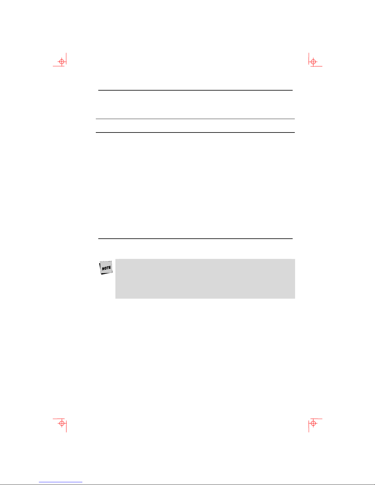
Table B-2 Other Available Local Functions
Local Functions 6-5
Function
Number
91
92
93
94
100
105
106
111
112
113
114
115
116
117
119
Function Function
Number
BS
CAN
ESC
DEL
UDK sequence
Soft reset
±Show controls
±Status display
±Split screen
Raise horizontal split
Lower horizontal split
Adjust window to show cursor
± Cursor drag
± Insert mode
Home & Clear
120
121
122
123
124
125
126
138
139
142
144
151
155
156
157
± means the function switches alternately between on and off.
An Accessibility aid feature allows the modifier keys to remain
in effect after they are released. A small icon in the status line
indicates its state.
To enable: Press any modifier key five times. To disable: Press and
hold a modifier key while you press another key.
Function
Page 0
Page 1
Page 2
Page 3
Page 4
Page 5
Page 6
Prev Page
Next Page
Slow Scroll
Fast Scroll
±Keyclick
±Block mode
Block mode on
Block mode off
Page 52

6-6 Keyboard Function Keys
Compose Characters
The tables at the end of this manual describe how to compose
characters for the Multinational and ISO Latin 1 character sets
for a VT keyboard.
In the tables,
column ...
3- A three-stroke key sequence beginning with the
2- A two-stroke key sequence beginning with a
Within the tables… Represents ...
(sp) A space character.
Canadian-English Danish, Dutch, Hebrew, Hungarian, Italian,
Norwegian, Polish, Romanian, Russian, SCS, Turkish-F,
Turkish-Q, UK, and US keyboards do not have non-spacing
diacritical marks regardless of the character mode.
Represents ...
Characters to be composed.
Compose key.
non-spacing diacritical accent key.
 Loading...