

Page 1

Hardware User’s Guide
Page 2

Trademark Credits
Boundless Technologies and its logo are trademarks of Boundless Technologies, Inc.
It is the p olicy of Boundless Technologies, Inc. to improve products as new tec h nology,
components, software, and firmware become available. Boundless Technologies, therefore,
reserves the right to change specifications without prior notice.
All features, functions, and operations described he rein may not be marketed by Boundless
Technologies in all parts of the world. In some instances, photographs are of equipment
prototypes. T herefore, before using this document, consult your Boundless Technologies
representativ e or Boundless Techno logies office for information that is applicable and current.
Note that Boundless Technologies appreciates re ceiving suggestions and comm ents on its
publications.
Copyright © Bou ndless Technologies, Inc . 2000.
Hauppauge, New York
All rights reserved.
Printed in USA
Page 3

i
Contents
Hardware User’s Guide................... .................................... ..............1
Trademark Credits....................................... .................................... .2
Contents.............................................................................................i
Getting Started..................................................................................ii
Safety Notices .............. ....................................................................................ii
Danger Notices.................................................................................................................ii
Caution Notices...............................................................................................................iii
Warning Notices....... .................................................................... ...................................iii
How to Connect or Disconnect Your Capio II...................... .........................iv
Chapter 1: Introduction.....................................................................1
Chapter 2: Site Preparation...............................................................2
Customer Responsibilities.. ............................................................ .................2
Physical Specifications.. ...................................................................................2
Environmental Information.......... ............................................................ .......3
Operating Environment.................................................................................................. 3
Storage Environment.......................................................................................................3
AC Power Requirements.............. ................................ ....................................3
Chapter 3: Hardware Setup...............................................................4
Peripheral Port Pinouts....................................................................................5
Regulatory State m ent s......................................................................6
FCC Cautionary Statements.......................... ...................................................6
FCC Telecom Statement...... ............................................................................6
European Telecom Statement .........................................................................6
CE Mark Statement.............................................. ............................................7
User Installed Accessories Statement.............. ................................ ................7
Index ...............................................................................................10
Page 4

ii
Getting Started
This section of the manual contains important safety and setup informat ion. Please read at least
this section of the manual before using your Capio II terminal.
Safety Notices
This manual contains three kinds of safety notices: Danger notices, Caution notices, and Warning
notices.
Danger Notices
A danger notice indicates a hazard that co uld possibly cause death or serious personal injury.
The following danger notices are used throughout t h is manual.
DANGER:
This product contains electrical power and other sensitive components within its
case, and is not designed for consumer access or replacement of components. If
your Boundless Technologies product requires repair or you wish to add any
component that requires opening the product case, you should contact your
nearest authorized service provider for assistance. Any attempt to repair your
product or any efforts to install or replace components within the product case by
an unauthorized person could expose that person to risk of electrical shock and
will cause your product warranty to be void.
DANGER:
To prevent a possible electrical shock when installing the device, ensure that the
power cord for that device is unplugged before installing signal cables.
DANGER:
To avoid a shock haza rd:
The power cord must be connected to a properly wired and earthed receptacle.
•
Any equipment to which this product will be attached must also be connected
•
to properly wired receptacles.
Page 5

iii
DANGER:
The device’s switch is not the main disconnect . T he device’s main power disconnect
is the detachable line cord.
Caution Notices
A caution notice indicates a hazard that could possibly cause minor personal injury.
Warning Notices
A warning not ice indicates the possibility of damage to a program, device, system, or data.
WARNING:
This device relies on natural convect ion cooling.
Page 6

iv
Sicherheitshinweise
Dieses Handbuch enthält drei Arten von Sicherheitshinweisen. Gefahrenhinweise,
Vorsichtshinweise und Warnhinweise.
Gefahrenhinweise
Ein Gefahrenhinweis zeigt eine Ge fahr an, die wahrscheinlich Tod oder er nsthafte
personenbezogene Verletzungen zur Folge haben kann. Die nachstehenden Gefahrenhinweise
werden im gesamten Handbuch durchgängig benutzt.
Gefahr:
Dieses Produkt beinhaltet in seinem Gehäuse stromführende Teile und andere
empfindliche Bauteile. Es ist nicht vorgesehen, dass Kunden Zugang zu den
Bauteilen haben oder diese austauschen. Falls Ihr Boundless Technologies Gerät
repariert werden muss oder Sie eine Erweiterung von Komponenten wünschen, die
eine Öffnu ng d e s G ehäu se s er forde rt , sollten Sie Ihren nächs t g eleg e nen au t ori siert en
Fachhändler anrufen und um Unterstützung nachsuchen. Jeder Reparaturversuch
innerhalb Ihres Gerätegehäuses durch eine nicht autorisierte Person oder jeder
Versuch innerhalb des Gehäuses ein Bauteil zu installieren oder durch eine nicht
autorisierte Person auszutauschen, kann diese Person dem Risiko eines
Stromschlages au sgesetzt werden und e s verursacht das Erlöschen der Garantie für
das Produkt.
Gefahr:
Um einen elektrischen Stromschlag zu vermeiden, wenn das Teil eingebaut wird,
muss sicherg estellt sein, dass das Stromkabel di eses Teils ausgesteckt ist, bevor die
Signalleitungen installiert warden.
Gefahr:
Vermeiden eine r Stromschlagg efä hrdung:
Das Stromkabel mu ss mit einer korrekt verdrahteten und geerdeten
•
Steckerbuchse verbunden werden.
Jedes Gerät mit dem dieses Produkt verbunden wird, muss ebenso mit einer
•
Page 7

v
korrekt verdrahteten und geerdeten Steckerbuchse verbunden werden.
Gefahr:
Der Geräteschalter ist nicht der Hauptschalter. Der Hauptstromtrenner ist das
herauszuziehende Stromkabel.
Vorsichtshinweise
Ein Vorsichtshinweis zeigt eine Gefährdung an, die kleinere Verlet zungen bei Personen
hervorrufen kann.
Warnhinweise
Ein Warnhinweis zeigt die Möglichkeit der Zerstörung eines P r ogramms, Geärteteils, Systems
oder Daten an.
Warnung:
Dieses Gerät beru ht auf natürlicher Konvektionskühlung.
Page 8
vi
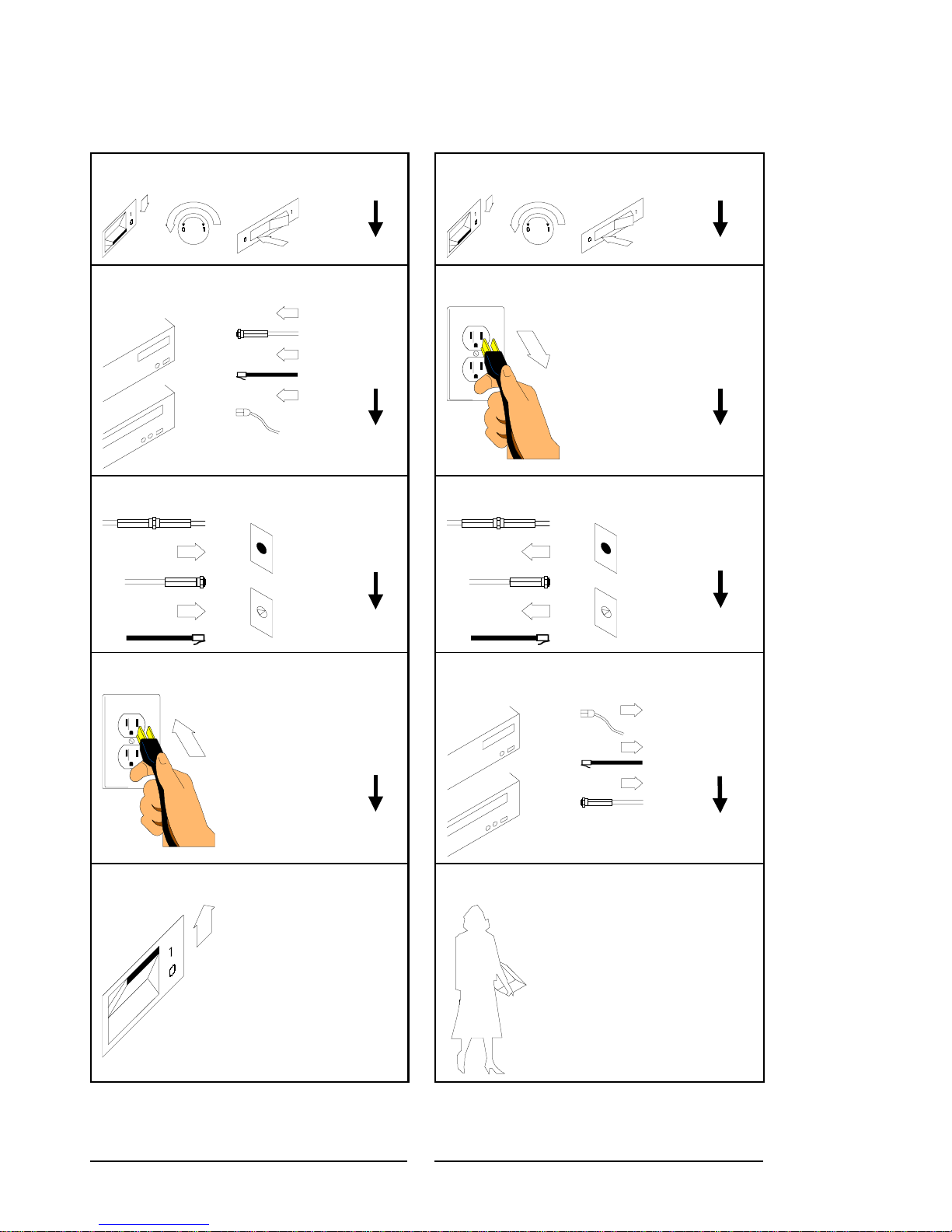
How to Connect or Disconnect Your Capio II
To Conn ect: To Dis connect:
First, turn everything OFF.
Attach all cables to devices.
Attach signal cables to receptacles.
First, turn everything OFF.
Remove power cord from outlet.
Remove signal cables from receptacles.
Attach power cord to outlet.
Turn device ON.
Remove all cables from devices.
You may now take it with you.
Note: In the UK, by law, the
telephone cable must be connected
after the power cord.
Note: In the UK, by law, the power
cord must be disconnected af ter the
telephone line c able.
Page 9
1
Chapter 1: Introduction
Thank you for purchasing a Capio II from Boundless Technologies. The Capio I I is the most
unique net work computer , providing the b r oadest application access capability availab le in a
network computer today. Capio II’s flexibility allows you to migrate at your pace, giving you the
ability to meet your current and future requirements.
Boundless Technologies designed the Capio II t o be a flexible network co mputer. The Capio II
can be configured with options such as various amounts of DRAM and additional flash memory.
However, the Capio II is a networ k computer, NOT
change to the hardware configurations such as adding or changing the options listed above may
impair or even damage the product. Only product as shipped from the Boundless Technologies
factory is fully certified to operate as specified.
a general purpose PC. Any unauthorized
Boundless Technologies provides a full range of services for customers who wish to utilize some
of the advanced hardware feature s of Capio II. Many configurations and options are possible, and
Boundless Tec hnologies Professiona l Services personnel are available to help configure the Capio
II to meet your needs. Depending upon your requirements, charges or fees may be levied for such
services. For further information, please contact the Boundless Technolog ies Professional
Services group at the follow ing number: 1-800-231-5445, extension 7440, or 631-342-7400
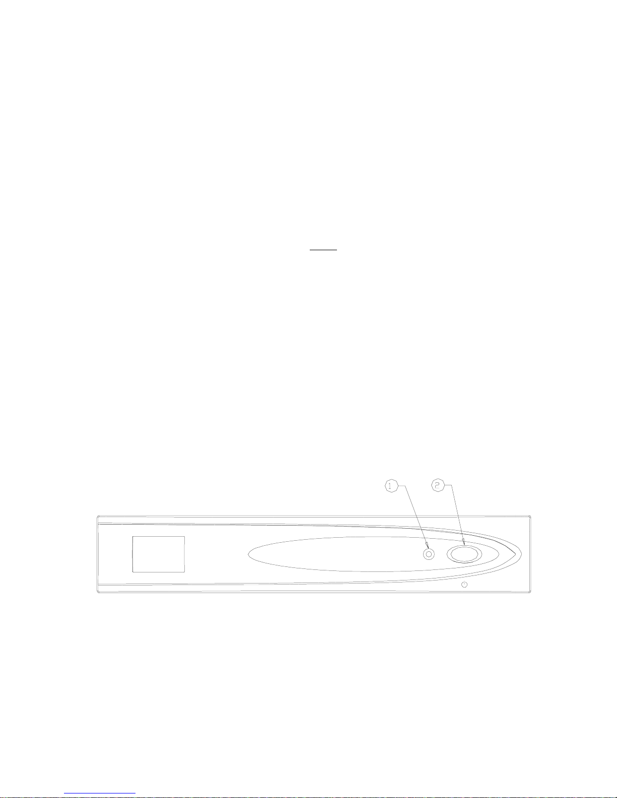
The following illustration shows the location of the power switch and st atus indicators on the
front of a Capio II.
Figure 1: Front panel
1: Status LED 2: Operate /Standby Switch
Page 10

Chapter 2: Site Preparation
This section de scribes how to prepare a site before installing Boundless Technologies equipment .
Failure to comply with the requirements specified in this section may cause damage to the
equipment. The responsibility for ensuring that the site is prepared in compliance with this
section lies with the customer.
Customer Responsibilities
Before installing the Capio II, ensure that:
The unit has adequate natural air flow if operating above 35
•
The Capio II has enough space for adequate ventil ation.
•
The site wiring is appropriate.
•
The site location is away from other equipment capable of generating elec trical noise,
•
electromagnetic interference, heat, etc.
All applicable codes, regulations, and laws are met.
•
The environmental requirements of the Capio II are met.
•
Floor coverings limit or control ele ctricity build up and discharg e.
•
Physical Specifications
Height (mounted horizontally) 1.9”
o
C (95o F).
Width (mounted horizontally) 9.8”
Depth (mounted horizontally) 9.7”
Height (mounted vertically in stand) 10.1”
Width (mounted vertically in stand) 3.4”
Depth (mounted vertically in stan d) 10.2”
Maximum Shipping Weig ht
(with keyboard)
Minimum Shipping Weight
(without k ey board)
The Capio II is designed for either vertical or horizontal installation. When installed verti ca lly, the
Capio II must be mounted in the supplied stand. Always make sure the air vents ar e not blocked,
to allow for prop er heat dissipation.
12.0 lbs.
9.1 lbs.
Page 11

3
Environmental Information
Operating Environment
Relative Humi dity 20% to 80%, non-cond ensing
Temperature Range
(With unrestricted natural
convection cooli ng or fan
installed.)
Temperature Range
(With restricted natural conve ction
cooling.)
Maximum Operating Altitude 9,843 feet (3,000 meters)
50° to 104° F (10° to 40° C)
50° to 95° F (10° to 35° C)
Storage Environm ent
Temperature Range
Maximum Storage Altitu de 40,000 feet (12,192 meters)
14° to 120° F (-10° to 50° C)
AC Power Requirements
Voltage t r ansients, line noises, s u rges, sags, impulses, and spikes m ay be experienced routinely or
sporadically. When such phenomena occur, the use of protective devices may be required to
ensure proper o peration of the equipment.
For maximum electrical integrity, the power cable should be connected to a circuit that does not
supply power to switched inductive loads, such as motors, air conditioners, etc.
The following table shows the ac pow er voltage and frequency requirements for the Capio II:
Voltage Range 100 - 240 VAC
Current 0.58A maximum
Frequency 50 or 60 Hz
Page 12
A
Chapter 3: Hardware Setup
1
C INPUT
CAUTION: H IGH VOLTAGE
INSIDE UNIT
LINE
MIC
OUT
LINK
2
3
4
IN
5
6
USB
NETWORK
7 9
8
KYBD
MOUSE
DISPLAY
10
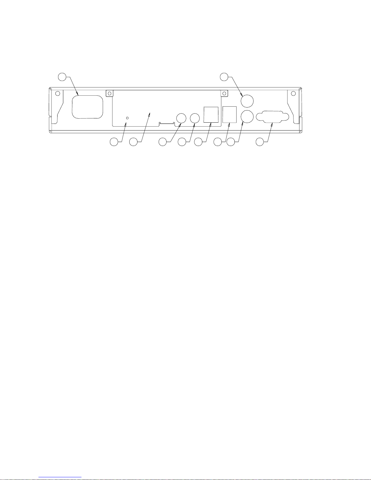
Figure 2 - Back panel Connections
1: AC Line Receptacle 2: Link Indicator
3: Option connect or area 4: Audio Line Out (stereo)
5: Audio M icrophone In 6: Dual USB
7: 10/100BaseT Ethernet 8: PS/2 Keyboard
9: PS/2 Mouse 10: VGA Display
1. Remove the logic unit, line cord, and accessories from the carton and set the logic unit on a
flat work-surface.
2. Connect the AC power cord, mouse, and keyboard to the appropriate connectors on the back
panel of the log ic unit as shown in Figure 2. (See safety notices on page vi)
3. Connect a VGA or SVGA monitor to the logic unit. The monitor may be placed on top of
the logic unit if the room ambient does not exceed 3 5
o
C (95o F).
4. Depending on your hardware, connect to the host:
If you use 10BaseT, connect a Category 5 cable between the logic unit and the network.
•
If you use a direct serial connection, connect an RS232 cable to th e ser ial port (on
•
Serial/Parallel Option). Note that a “null m o dem” connection may be required,
depending on your host’s serial port configuration. Refer to Peripheral Port Pinouts on page
5, if required.
If you use a modem, connect t he modem to the serial port (on Ser ial/Parallel Option).
•
5. Please refer to the Software Users Guide for additional information.
Page 13

5
Peripheral Port Pinouts
The optional serial port (COM1) uses a DB9 male connector and the DTE configuration shown
below (designed for use with a NULL mod em):
Pin Function
1 CD
2 RD
3 TD
4 DTR
5 GND
6 DSR
7 RTS
8 CTS
9 RI
The optional parallel port uses a D B 25 female connector configured as shown below:
Pin Function Pin Function
1 STROBE 10 ACK
2 D0 11 BUSY
3 D1 12 PE
4 D2 13 SLCT
5 D3 14 AUTOFD
6 D4 15 ERR
7 D5 16 INIT
8 D6 17 SLCT IN
9 D7 18-25 GND
Page 14

Regulatory Statements
FCC Cautionary Statements
Caution
Changes or modifications not expressly approved by Boundless Technologies could void the
user’s author ity to operate this equipment.
Note
This equipment has been tested and found to comply with the limits for a Class A digital device,
pursuant to Part 15 of the FCC Rules. These limits are designed to pr ovide reasonable pro tection
against harmful interference when the equipment is operated in a commercial environment. This
equipment generates, and uses, and can radiate radio frequency energy and, if not installed and
used in accordance with the instruction manual, may cause harmful interference to radio
communications. Operation of this equipment in a residential area is likely to cause interference in
which case the user will be required to correct the interference at his own expense.
FCC Telecom Statement
This equipment complies with the Part 68 of the FCC Rules. On the bottom of this equipment is
a label that con tains, among other information, the FCC registration number, and the Ringer
Equivalence Number (REN) for this equipment. If requested, this information must be provided
to the telephone company.
The REN is u sed to determ ine the quantity of devices, which may be connected to the
telephone line. E xcessive REN’s on the t elephone lines may result in the devices not ringing in
response to an incoming call. In most, but not all, areas the sum of the REN’s should not excee d
five. To be certain of the number of devices that may be connected to the lin e, as determined by
the total REN’s contact the telephone company to determine the maximum REN for the calling
area.
If this equipment causes harm t o the telephone network, the telephone company will notify
you in advance . If advance notice isn’t practical, th e telephone company w i ll notify you as soon as
possible. Also you will be advised of your right to file a complaint with the FCC.
European Telecom Statement
Warning
The Capio II is intended to be connected to a Network Centric System. Do Not connect this
terminal to the Telecom System.
Page 15

7
CE Mark St atement
This unit has been tested and found to comply with the EC Directives:
EMC Directive 89/336/EEC (amended by 93/68/EEC)
Low Voltage Directive 73/23/EEC (amended by 93/68/EEC)
User Instal led Accessories Statement
Danger
To reduce the risk of shock do not ope n the enclosure. Servicing of the Capio II unit is to be
performed onl y by qualified serv ice personnel.
Page 16

FCC Warnhinweise
Vorsicht
Austausch oder Modifikationen, die nicht ausdrücklich von Boundless Technologies genehmigt
sind, heben die Betreibererlaubnis für dieses Gerät auf.
Europäische Telekom Hinweis
Warnung
Das Capio II ist vorgehen an ein Zentrales Netzwerksystem (Network Centric System)
angeschlossen zu werden. Dieses Terminal nicht an das Telekom System anschliessen!
Anwenderhinweis über eingebautes Zubehör
Gefährdung
Um das Risiko eines Stromschlages zu ver mindern, darf die Anlage nicht geöffnet werden. Die
Wartung/Instandsetzung des Capio II d arf nur von qualifiziertem Kundend ienstpersonal
ausgeführt werden.
Page 17

9
Technical Support
Questions about the Capio II should be directed to the Technical Support Department of the
distributor from which you obtained your Boun dless Technologies equipment. When requesting
assistance, please have all pertinent information available including any error messages that may
have appeared either on the Capio II or the server.
If your distributor fails to provide adequate support for your needs, please contact the Boundless
Technologies Technical Support Department directl y. You will be required to provide the name
of your dist ributor, and a de scription of the problem as described above.
Boundless Technologies provides Te chnical Support for all its Desktop products (Network
Computers & Text Terminals). Calls limited to the specific configuration or setup of Bound less
products are handled free of charge*. Support incidents requiring systems ad ministration or
systems integ r ation related support is available to technical support contract holders or can be
handled on a per-incident-basis.
Boundless Technologies can be reached at:
Voice: 1-800-231-5445 ext. 7259 or 1-631-342-7259
Fax: 1-631-342-7378
Email: [email protected]
BBS: 1-631-342-7950 1200/14400 baud
8 data bits, 1 stop, no parity
ftp: ftp.boundless.com
web: http://www.boundless.com
In Europe, please contact your local equipment supplier
*Free config uration and setu p assistance is limited to 90 days from installation.
Page 18

Index
A
AC Power Requirements, 4
Accessories, User Installed, Statement, 7
C
Caution Notices, iii
Connect Your Capio II, How to, iv
Customer R esponsibilities, 3
D
Danger Notices, ii
Disconnect Your Capio II, How to, iv
E
Environment
Operating, 4
N
Notices
Caution, iii
Danger, ii
Safety, ii
Warning, iii
O
Operating Environment, 4
P
Peripheral Port Pinouts, 6
Physical Specifications, 3
Power Requirements, 4
Preparation, Site, 3
Storage, 4
Environmental Information, 4
European Tel ecom Statement, 7
F
FCC Cautionary Statements, 7
G
Getting Started, ii
H
Hardware Setup, 5
Help. See Technical Support
I
Information, Environmental, 4
R
Regulatory Statements, 7
Requirements, Power, 4
Responsibilities, C us tom er , 3
Page 19

S
Safety Notices, ii
Setup, Hardware, 5
Site Preparation, 3
Specifications
Environmental, 4
Physical, 3
Statement
European Telec om, 7
User Installed Accessories, 7
Statements
FCC Cautionary, 7
Regulatory, 7
Storage Environment, 4
T
Technical Support, 8
Telecom, European, Statement, 7
U
User Installed Accessories Statement, 7
W
Warning Notices, iii
Support, Technical, 8
Page 20

100 Marcus Boulevard
P.O. Box 18001
Hauppauge, NY
11788-8801
598-0013321
 Loading...