

Page 1
BY OUNDLESS ECHNOLOGIES
B T
AD DS 5300 Win CE 6.0
User’s Manual
Page 2

TABLE OF CONTENTS
CHAPTER 1 License Agreement ...................................................................................................…....2
CHAPTER 2 Introduction of main User Interface.........................................................................…....5
2.1 WBT’s..........................................................................................................................…..5
2.2 Terminal Specifications ...............................................................................................… . . 5
2.3 Terminal Features ......................................................................................................… . .6
2.4 Terminal Overview .....................................................................................................… . . 6
2.4.1 Administrator/User mode ......................................................................................… . . 6
2.4.2 Programs...............................................................................................................…..7
CHAPTER 3 Introduction of main User Interface.........................................................................…..10
3.1 Desktop........................................................................................................................…..10
3.1.1 Items on Desktop..................................................................................................…..10
3.1.2 Properties ............................................................................................................…..11
3.2 Start Menu .................................................................................................................…..15
3.2.1
3.2.2 Programs ..............................................................................................................…..16
3.2.3 Connections..........................................................................................................…..19
3.2.4 Settings .................................................................................................................…..20
3.2.5
3.2.6 Shutdown l ............................................................................................................…..39
3.3
CHAPTER 4 Connections Management........................................................................................…..43
4.1 Creating New Connections..........................................................................................…..44
4.1.1 Choosing a Connection Protocol..........................................................................…..44
4.2.3 Local Resource Tab………………………………………………………………........….47
4.2.4 Programs Tab………………………………………………………………………….......49
4.2.5 Experience Tab……………………………………………….......……………………….49
4.3 ICA Connection ...........................................................................................................…..51
4.3.1 Creating a New ICA Connection Entry.................................................................…..51
4.3.2 Connecting to a Citrix Server...............................................................................…..55
4.3.3 Changing a Co nnection Entry..............................................................................…..56
4.3.3.1 To change the properties of a connection entry ............................................…..56
4.3.3.2 Specifying an Application to Run after Connecting to a Citrix Server ...........…..57
4.3.3.3 Specifying Logon Information ........................................................................…..58
4.3.3.4 Changing the Window Properties ..................................................................…..59
4.3.3.5 Setting Connection Entry Options..................................................................…..60
4.3.3.6 Changing the Title of the Connection Entry...................................................…..61
4.3.3.7 Configuring Firewall Settings.........................................................................…..62
4.4 Microsoft Internet Explorer Connection.......................................................................…..64
4.4.1 To Make a New Microsoft Internet Explorer Connection ...................................…..64
4.4.2 To Start a Microsoft Internet Explorer Connection.............................................…..69
4.5 TERMTEK Terminal Emulation ...................................................................................…..70
4.6 Microsoft VNC Viewer .................................................................................................…..72
CHAPTER 5 Advanced Function for Connections.......................................................................…..74
5.1 Multiple Auto Start-Up .................................................................................................…..74
5.2 Multiple Auto Reconnect..............................................................................................…..75
Administrator/User mode
Startup
Taskbar........................................................................................................................…..40
.................................................................................................................…..38
..................................................................................…..15
Page 3

CHAPTER 6 Control Panel .............................................................................................................…..76
6.1
6.2 Owner..........................................................................................................................…..76
6.2.1 Identification .......................................................................................................…..76
6.2.2 Notes.....................................................................................................................…..76
6.2.3 Network ID ............................................................................................................…..76
6.3 System.........................................................................................................................…..77
6.3.1 General...............................................................................................................…..77
6.3.2 Memory .............................................................................................................…..77
6.3.3 Device Name......................................................................................................…..77
6.3.4 Copyrights ..........................................................................................................…..77
6.3.5 Network Information ...........................................................................................…..78
6.4 Display.........................................................................................................................…..78
6.4.1 Display ..................................................................................................................…..78
6.4.2 Screensaver..........................................................................................................…..78
6.4.3 Background...........................................................................................................…..79
6.4.4 Appearance ..........................................................................................................…..79
6.5 Mouse..........................................................................................................................…..79
6.6 Sounds ........................................................................................................................…..80
6.7 Add/Remove Programs ...............................................................................................…..80
6.7.1 Add Programs.......................................................................................................…..80
6.7.2 Remove Programs................................................................................................…..81
6.8 Date/Time ....................................................................................................................…..81
6.9 Certificates...................................................................................................................…..81
6.10 System Info .................................................................................................................…..82
6.10.1 General ...............................................................................................................…..82
6.10.2 Component .........................................................................................................…..82
6.11 Citrix ICA Configure ....................................................................................................…..83
6.11.1 Configuring Hotkeys ...........................................................................................…..83
6.11.2 Configuring Global Preferences .........................................................................…..84
6.11.3 Server Location...................................................................................................…..85
6.11.4 Firewall Settings .................................................................................................…..86
6.12 Regional Settings ........................................................................................................…..87
6.12.1 Regional Settings................................................................................................…..87
6.12.2 User Interface Language....................................................................................…..88
6.12.3 Input Language...................................................................................................…..88
6.13 Storage Manager ........................................................................................................…..88
6.14 USB Manager..............................................................................................................…..89
6.15 FTP Update.................................................................................................................…..89
6.15.1 Update ................................................................................................................…..90
6.15.2 Back-up...............................................................................................................…..90
6.16 Ping .............................................................................................................................…..91
6.17 Thin Printer..................................................................................................................…..91
6.18 Input Panel ..................................................................................................................…..91
6.19 LPD .............................................................................................................................…..92
6.19.1 Setup for LPD .....................................................................................................…..92
6.19.2 Add a remote printer...........................................................................................…..93
6.19.3 LPD Printing........................................................................................................…..96
6.20 RM Agent Configuration ..............................................................................................…..97
6.20.1 RM Agent Configure.............................................................................................…..97
6.20.2 Authentication .......................................................................................................…..98
6.21 Touch Panel Settings .......................................................................................
6.22 Win VNC Server ..........................................................................................................…..99
6.23 Terminal Service Client License .................................................................................…..99
Keyboard
.......................................................................................................................…..76
...........…..99
Page 4

6.24 Printer..........................................................................................................................…100
6.24.1 Select the Printer Port…………………………………………………………...............101
6.24.2 Select the Printer Model…………………………………………………………..……..102
6.24.3 User Defined ……………………………………………………………………………...104
6.24.4 Finish the Setup Wizard………………………………………………………...………..106
6.25 Diagnostic Tool ...........................................................................................................…107
CHAPTER 7 User Security Control................................................................................................…108
7.1 Administrator Mode and User Mode............................................................................…108
7.2
7.2.1
7.2.3 User Mode Control…………………………………………………..………………….112
Appendix A.
Function Hot-keys List
Function
……………………………………………………………………………...……………..113
User Security Control tool
User Security Option
7.2.2 User Security Password……………………………………………………..…………112
................................................................................................…109
................................................................................................ 110
Page 5

Trademarks
ICA 3 is a registered trademark and MetaFrame is a trademark of Citrix Systems Inc.
Microsoft and Windows are registered trademarks of Microsoft Corporation.
All other products are trademarks and/or registered trademarks of their respective companies.
The Energy Star emblem does not represent endorsement of any product or service.
Specifications subject to change without notice.
FCC Statement
This equipment has been tested and found to comply with the limits for either Class A or Class B digital devices,
pursuant to Part15 of the FCC Rules. These limits are designed to provide reasonable protection against
harmful interference in a residential installation. This equipment generates, uses, and can radiate radio
frequency energy and, if not installed and used in accordance with the instructions, may cause harmful
interference to radio communications. However, there is no guarantee that interference will not occur in a
particular installation. If this equipment does cause harmful interference to radio or television reception, which
can be determined by turning the equipment off and on, the user is encouraged to try to correct the interference
by one or more of the following measures:
§ Reorient or relocate the receiving antenna.
§ Increase the separation between the equipment and the receiver.
§ Connect the equipment into an outlet on a circuit different from that to which the receiver is connected.
§ Consult the dealer or an experienced radio/TV technician for help.
CAUTION
Danger of explosion if battery is incorrectly replaced.
Replace only with the same or equivalent type
recommended by the manufacturer.
Dispose of used batteries according
to the manufacturer’s instructions.
Page 6

License Agreement
YOU SHOULD CAREFULLY READ THE FOLLOWING TERMS AND CONDITION S BEFORE USING THIS EQUIPMENT WHICH
CONTAINS SOFTWARE IN A NON-VOLATILE FORMAT AND CERTAIN OTHER INTELLECTUAL PROPERTY (HEREAFTER
“FIRMWARE”). USING THIS EQUIPMENT INDICATES YOUR ACCEPTANCE OF THE FOLLOWING TERMS AND CONDITIONS.
Grant
You may use the Firmware in or in conjunction with the Equipment as provided to You. You may transfer ownership of the Equipment,
including the right to use the Firmware to another party so long as that party agrees to accept these terms and conditions.
YOU MAY NOT USE, COPY, MODIFY, TRANSLATE OR TRANSFER THE FIRMWARE, OR MODIFICATION THEREOF, IN WHOLE OR
IN PART, EXCEPT AS EXPRESSLY PROVIDED FOR IN THIS LICENSE. YOU MAY NOT DECOMPILE, REVERSE ENGINEER OR
OTHERWISE DECODE OR ALTER THE SOFTWARE CONTAINED IN THE FIRMWARE.
Limited Software Warranty and Disclaimer
We warrant that, for a period of ninety (90) days from the date of shipment, the Firmware will, under normal use, be free from defects in
materials and workmanship in the EPROM (or similar storage device). The foregoing warranty shall not apply to any Firmware that has been
used in violation of this Agreement. During this limited warranty period We will provide support by phone on a best-efforts basis. We may, in
addition to the above, replace any defective Firmware with a functionally equivalent product. The foregoing shall be Your exclusive remedy
for any breach of warranty hereunder. You assume responsibility for choosing the Equipment containing the Firmware to achieve your
intended results, and for the installation, use and results obtained from the Equipment and Firmware.
EXCEPT FOR THE ABOVE EXPRESS LIMITED WARRANTIES, WE MAKE AND YOU RECEIVE NO WARRANTIES ON THE FIRMWARE,
EXPRESS, IMPLIED, OR STATUTORY, OR IN ANY OTHER PROVISION OF THIS AGREEMENT OR COMMUNICATION WITH YOU,
AND WE DISCLAIM ANY IMPLIED WARRANTIES OF M ERCHANTABILITY, NON-INFRINGEMENT AND FITNESS FOR ANY
PARTICULAR PURPOSE. WE DO NOT WARRANT THAT THE FUNCTIONS CONTAINED IN THE PRODUCT WILL MEET YOUR
REQUIREMENTS OR THAT THE OPERATION WILL BE UNINTERRUPTED OR ERROR FREE.
SOME STATES DO NOT ALLOW LIMITATIONS ON HOW LONG AN IMPLIED WARRANTY LASTS SO THE ABOVE LIMITATION MAY
NOT APPLY TO YOU. THIS WARRANTY GIVES YOU SPECIFIC LEGAL RIGHTS. YOU MAY ALSO HAVE OTHER RIGHTS WHICH
VARY FROM STATE TO STATE.
Limit of Liability
UNDER NO CIRCUMSTANCES SHALL WE BE LIABLE FOR LOSS OF DATA, COST OF COVER, OR ANY INCIDENTAL OR
CONSEQUENTIAL DAMAGES, HOWEVER CAUSED AND ON ANY THEORY OF LIABILITY. THESE LIMITATIONS SHALL APPLY EVEN
IF WE OR OUR RESELLERS HAVE BEEN ADVISED OF THE POSSIBILITY OF SUCH DAMAGES, AND NOTWITHSTANDING ANY
FAILURE OF ESSENTIAL PURPOSE OF ANY LIMITED REMEDY PROVIDED HEREIN.
YOU AGREE THAT THESE ARE THE ONLY APPLICABLE TERMS OF AGREEMENT BETWEEN US COVERING FIRMWARE AND THAT
THEY SUPERSEDE ANY OTHER COMMUNICATIONS (ORAL OR WRITTEN) BETWEEN US RELATING TO THE FIRMWARE.
U.S. Government Restricted Rights
The Firmware is provided with RESTRICTED RIGHTS. Use, dupli cation or disclosure by the Government is subject to restrictions as set
forth in subparagraph (c)(1)(ii) of the Rights in Technological Data and computer software clause at DFARS 252.227-7013 or in
subparagraphs (c)(1) and (2) of the Commercial Computer Software-Restricted Rights at 8 C.F.R. 52-227-19 as applicable.
Page 7

EULA for Microsoft® Windows® CE Operating System for Windows-based
Terminal Devices Version 1.5
IMPORTANT—READ CAREFULLY
This End User License Agreement (EULA) is a legal agreement between you (either an individual or a single entity) and the
manufacturer (MANUFACTURER) of the special purpose computing device (SYSTEM) you acquired which includes certain
Microsoft software product(s) installed on the SYSTEM and/or included in the SYSTEM package (SOFTWARE). The SOFTWARE
includes computer software, the associated media, any printed materials, and any online or electronic documentation. By
installing, copying or otherwise using the SOFTWARE, you agree to be bound by the terms of this EULA. If you do not agree to the
terms of this EULA, MANUFACTURER and Microsoft Licensing, Inc. (MS) are unwilling to license the SOFTWARE to you. In such
event, you may not use or copy the SOFTWARE, and you should promptly contact MANUFACTURER for instructions on return of
the unused product(s) for a refund.
Software License
The SOFTWARE is protected by copyright laws and international copyright treaties, as well as other intellectual property laws and treaties.
The SOFTWARE is licensed, not sold.
Page 8

1.Grant of License
SOFTWARE includes software already installed on the SYSTEM
(SYSTEM SOFTWARE) and, if included in the SYSTEM package,
software contained on the CD-ROM disk and/or floppy disk(s)
labeled "Desktop Software for Microsoft Windows CE" (DESKTOP
SOFTWARE). This EULA grants you the following rights to the
SOFTWARE:
SYSTEM SOFTWARE
You may use the SYSTEM SOFTWARE only as installed in the
SYSTEM.
You may not reverse engineer, de-compile, or disassemble the
SYSTEM SOFTWARE, except and only to the extent that such
activity is expressly permitted by applicable law notwithstanding
this limitation.
Single SYSTEM
The SYSTEM SOFTWARE is licensed with the SYSTEM as a
single integrated product. The SYSTEM SOFTWARE installed in
Read Only Memory (ROM) of the SYSTEM may only be used as
part of the SYSTEM.
Single EULA
DESKTOP SOFTWARE
DESKTOP SOFTWARE might not be included with your SYSTEM.
If DESKTOP SOFTWARE is included with your SYSTEM, you may
install and use the component(s) of the DESKTOP SOFTWARE in
accordance with the terms of the end user license agreement
provided with such component(s). In the absence of a separate
end user license agreement for particular component(s) of the
DESKTOP SOFTWARE, you may install and use only one (1) copy
of such component(s) on a single computer with which you use the
SYSTEM.
Server, Use of Windows CE Op erating System for
Windows-Based Termi nal Devices with Microsoft Windows NT
Server, Terminal Server Edition
If the SOFTWARE is Windows CE operating system for
Windows-Based Terminal devices, the following special provisions
apply. In order to use the SYSTEM in connection with Windows NT
Terminal Server Edition, you must possess (1) a Client Access
License for Windows NT Server, Terminal Server Edition and (2)
an end user license for Windows NT Workstation or an end user
license agreement for Windows NT Workstation for
Windows-Based Terminal Devices (please refer to the end user
license agreement for Windows NT Server, Terminal Server Edition
for additional information). MANUFACTURER may have included a
Certificate of Authenticity for Windows NT Workstation for
Windows-Based Terminal Devices with the SYSTEM. In that case,
this EULA constitutes an end user license for the version of
Windows NT Workstation for Windows-Based Terminal Devices
indicated on such Certificate of Authenticity.
Back-up Copy
If MANUFACTURER has not included a back-up copy of the
SYSTEM SOFTWARE with the SYSTEM, you may make a single
back-up copy of the SYSTEM SOFTWARE. You may use the
back-up copy solely for archival purposes.
2.Description of Other Rights and Limit ations
Speech/Handwriting Recognition
If the SYSTEM SOFTWARE includes speech and/or handwriting
recognition component(s), you should understand that speech and
handwriting recognition are inherently statistical processes; that
recognition errors are inherent in the processes; that it is your
responsibility to provide for handling such errors and to monitor the
recognition processes and correct any errors. Neither
MANUFACTURER nor its suppliers shall be liable for any damages
arising out of errors in the speech and handwriting recognition
processes.
Limitations on Reverse Engineering, Decompilation and
Disassembly
The package for the SYSTEM SOFTWARE may contain multiple
versions of this EULA, such as multiple translations and/or multiple
media versions (e.g., in the user documentation and in the
software). Even if you receive multiple versions of the EULA, you
are licensed to use only one (1) copy of the SYSTEM SOFTWARE.
Rental
You may not rent or lease the SOFTWARE.
Software Transfer
You may permanently transfer all of your rights under this EULA
only as part of a sale or transfer of the SYSTEM, provided you
retain no copies, you transfer all of the SOFTWARE (including all
component parts, the media, any upgrades or backup copies, this
EULA and, if applicable, the Certificate(s) of Authenticity), and the
recipient agrees to the terms of this EULA. If the SOFTWARE is an
upgrade, any transfer must include all prior versions of the
SOFTWARE.
Termination
Without prejudice to any other rights, MANUFACTURER or MS
may terminate this EULA if you fail to comply with the terms and
conditions of this EULA. In such event, you must destroy all copies
of the SOFTWARE and all of its component parts.
3.Upgrades
If the SYSTEM SOFTWARE and this EULA are provided separate
from the SYSTEM by MANUFACTURER and the SYSTEM
SOFTWARE is on a ROM chip, CD ROM disk(s) or floppy disk(s),
and labeled "For ROM Upgrade Purposes Only" ("ROM Upgrade"),
you may install one copy of the ROM Upgrade onto the SYSTEM
as a replacement copy for the SYSTEM SOFTWARE originally
installed on the SYSTEM and use it in accordance with Section 1
of this EULA.
4.Copyright
All title and copyrights in and to the SOFTWARE (including but not
limited to any images, photographs, animations, video, audio,
music, text and "applets," incorporated into the SOFTWARE), the
accompanying printed materials, and any copy of the SOFTWARE,
are owned by MS or its suppliers (including Microsoft Corporation).
You may not copy the printed materials accompanying the
SOFTWARE. All rights not specifically granted under this EULA are
reserved by MS and its suppliers (including Microsoft Corporation).
5.Product Support
Product support for the SOFTWARE is not provided by MS, its
parent corporation, Microsoft Corporation, or their affiliates or
subsidiaries. For product support, please refer to
MANUFACTURER’s support number provided in the
documentation for the SYSTEM. Should you have any questions
Page 9

concerning this EULA, or if you desire to contact
MANUFACTURER for any other reason, please refer to the
address provided in the documentation for the SYSTEM.
6.Export Restrictions
You agree that you will not export or re-export the SOFTWARE to
any country, person, or entity subject to U.S. export restrictions.
You specifically agree not to export or re-export the SOFTWARE: (i)
to any country to which the U.S. has embargoed or restricted the
export of goods or services, which as of March 1998 include, but
are not necessarily limited to Cuba, Iran, Iraq, Libya, North Korea,
Sudan and Syria, or to any national of any such country, wherever
located, who intends to transmit or transport the products back to
such country; (ii) to any person or entity who you know or have
reason to know will utilize the SOFTWARE or portion thereof in the
design, development or production of nuclear, chemical or
biological weapons; or (iii) to any person or entity who has been
prohibited from participating in U.S. export transactions by any
federal agency of the U.S. government.
If the SOFTWARE is labeled "North America Only Version" above,
on the Product Identification Card, or on the SOFTWARE
packaging or other written materials, then the following applies:
The SOFTWARE is intended for distribution only in the United
States, its territories and possessions (including Puerto Rico,
Guam, and U.S. Virgin Islands) and Canada. Export of the
SOFTWARE from the United States is regulated under "EI
controls" of the Export Administration Regulations (EAR, 15 CFR
730-744) of the U.S. Commerce Department, Bureau of Export
Administration (BXA). A license is required to export the
SOFTWARE outside the United States or Canada. You agree that
you will not directly or indirectly, export or re-export the
SOFTWARE (or portions thereof) to any country, other than
Canada, or to any person or entity subject to U.S. export
restrictions without first obtaining a Commerce Department export
license. You warrant and represent that neither the BXA nor any
other U.S. federal agency has suspended, revoked or denied your
export privileges.
7.Note on Java Support
The SYSTEM SOFTWARE may contain support for programs
written in Java. Java technology is not fault tolerant and is not
PERFORMANCE OF THE SOFTWARE IS WITH
YOU.
No Liability for Consequential Damages
MANUFACTURER OR MANUFACTURER’S
SUPPLIERS, INCLUDING MS AND ITS SUPPLIERS,
SHALL NOT BE HELD TO ANY LIABILITY FOR
ANY DAMAGES SUFFERED OR INCURRED BY
THE END USER (INCLUDING, BUT NOT LIMITED
TO, GENERAL, SPECIAL, CONSEQUENTIAL OR
INCIDENTAL DAMAGES INCLUDING DAMAGES
FOR LOSS OF BUSINESS PROFITS, BUSINESS
INTERRUPTION, LOSS OF BUSINESS
INFORMATION AND THE LIKE), ARISING FROM
OR IN CONNECTION WITH THE DELIVERY, USE
OR PERFORMANCE OF THE SOFTWARE.
If you acquired this EULA in the United States, this
EULA is governed by the laws of the State of
Washington.
If you acquired this EULA in Canada, this EULA is
governed by the laws of the Province of Ontario,
Canada. Each of the parties hereto irrevocably
attorns to the jurisdiction of the courts of the Province
of Ontario and further agrees to commence any
litigation which may arise hereunder in the courts
located in the Judicial District of York, Province of
Ontario.
designed, manufactured, or intended for use or resale as on-line
control equipment in hazardous environments requiring fail-safe
performance, such as in the operation of nuclear facilities, aircraft
navigation or communication systems, air traffic control, direct life
support machines, or weapons systems, in which the failure of
Java technology could lead directly to death, pe rsonal injury, or
severe physical or environmental damage.
8.Limited Warranty
Limited Warranty
MANUFACTURER warrants that the SOFTWARE will perform
substantially in accordance with the accompanying written
materials for a period of ninety (90) days from the date of receipt.
Any implied warranties on the SOFTWARE are limited to ninety (90)
days. Some states/jurisdictions do not allow limitations on duration
of an implied warranty, so the above limitation may not apply to
you.
Customer Remedies
MANUFACTURER’S and its suppliers’ entire liability and your
exclusive remedy shall be, at MANUFACTURER’S option, either (a)
return of the price paid, or (b) repair or replacement of the
SOFTWARE that does not meet the above Limited Warranty and
which is returned to MANUFACTURER with a copy of your receipt.
This Limited Warranty is void if failure of the SOFTWARE has
resulted from accident, abuse, or misapplication. Any replacement
SOFTWARE will be warranted for the remainder of the original
warranty period or thirty (30) days, whichever is longer.
No Other Warranties
EXCEPT AS EXPRESSLY PROVIDED IN THE LIMITED
WARRANTY SECTION ABOVE, THE SOFTWARE IS PROVIDED
TO THE END USER "AS IS" WITHOUT WARRANTY OF ANY
KIND, EITHER EXPRESSED OR IMPLIED, INCLUDING, BUT
NOT LIMITED TO, WARRANTIES OF NON- INFRINGEMENT,
MERCHANTABILITY, AND/OR FITNESS FOR A PARTICULAR
PURPOSE. THE ENTIRE RISK OF THE QUALITY AND THE
PERFORMANCEOF THE SOFTWARE IS WITH YOU.
If this EULA was acquired outside the United States, then local
law may apply.
Should you have any questions concerning this EULA, please
contact the MANUFACTURER of your SYSTEM.
U.S. GOVERNMENT RESTRICTED RIGHTS
The SOFTWARE and documentation are provided with
RESTRICTED RIGHTS. Use, duplication, or disclosure by the
Government is subject to restrictions as set forth in
subparagraph (c)(1)(ii) of the Rights in Technical Data and
Computer Software clause at DFARS 252.227-7013 or
subparagraphs (c)(1) and (2) of the Commercial Computer
Software—Restricted Rights at 48 CFR 52.227- 19, as
applicable. MANUFACTURER is Microsoft Corporation/One
Microsoft Way/Redmond, WA 98052-6399
Page 10

2 Product Overview
A
A
A
2.1 WBTs
WBTs (Windows-based Terminals) are designed to connect to WTS (Windows Terminal Server) servers via RDP (Remote
Desktop Protocol), or Windows NT applications server via ICA (Independent Computing Architecture). RDP is the Windows
XP-based protocol for connecting to Windows terminal servers. ICA is a distributed presentation services protocol for
Windows NT server, allowing an application's user interface to execute on a Windows-based terminal while the application's
logic executes on the server.
2.2 Terminal Specifications
CPU
RAM DDR SO-DIMM 200 pins support DDR266/333/400 Up to 512MB
Flash Memory 32MB CF card standard, expandable to 1GB
Flash upgrade utility via Ethernet
Resolution Resolution up to 1600x1200 / 100 Hz 32 bit.
Video Memory Graphics utilizes system RAM
udio Support Full 16 bit stereo FM synthesis, 8 bit mini Microphone in
Networking Protocols 10/100 Base T Fast Ethernet, Twisted Pair (RJ45)
TCP/IP with DNS, DHCP and PPP
Load balancing supported by Citrix ICA
Remote modem dial up with Citrix ICA
Communications Protocols MS RDP / Citrix ICA
One Parallel Port Bi-directional centronics compatible, DB-25
One Serial Port DB-9 pin male connector with RS-232C, up to 115.2K bps
One Display Port
USB Port Four USB ports
udio Port Line out, Micro phone In
KB & Mouse Interface Enhanced PS/2 keyboard and mouse interface
Operation System Microsoft Windows CE.NET
Set-up & Configuration Local power-on boot, simple start-up wizard for set-up
Server Operating System
Support
Terminal Emulations Console ANSI, VT 420/320/2 20/100/52, Wyse 120/60/50+/325
Support TVI 925, TVI 910+, ADDS A2, IBM3270, IBM5250.
AMD Geode LX700 / LX800 (433 MHz / 500 MHz)
nalogue VGA type video output (DB-15)
Configurable automatic login, Multi-language KB support,
Multiple auto-startup support
RDP:
Microsoft Windows NT4.0 + TSE.
Microsoft Windows 2000 Server Family.
Microsoft Windows 2003 Server Family.
Microsoft Windows XP with RDP protocol
ICA:
Citrix Winframe
Microsoft Windows NT4.0 + TSE+ Citrix Metaframe
Microsoft Windows 2000 + Citrix Metaframe.
Microsoft Windows 2000/ Windows 2003 + Citrix MetaframeX P.
____________________________
ADDS 5300 Win CE
5
Page 11
2.3 Terminal Features
Physical Characteristics
Height 190 mm (7.48 in)
Width 40 mm (1.57 in)
Depth 140 mm (5.51 in)
Net Weight 700 g (1.08 lbs)
Power Cord 6 ft (1.83m)
Environmental
Operating Temperature
Non-operating Temperature
Operating Humidity 10% to 90%, non-condensing
Operating Altitude 0 to 2,000 ft ASL
Nonoperating Altitude 0 to 40,000 ft ASL
Regulatory
EMC Terminal/Power Brick FCC B, CE, CB, TUV, CUL, C-TICK, BSMI,VCCI
Safety Power Brick UL1950, CB IEC60950.
5 to 40℃ (41 to 104℉ )
-40to 60℃ (-40 to 150℉)
Installation
2.4 Terminal Overview
2.4.1 Connecting the Terminal
Follow these instructions to connect the terminal to its peripheral devices:
A. Connect the keyboard to the keyboard connector.
B. Connect the mouse to the mouse connector.
C. Connect the 10/100-T network cable to the RJ-45 network connector.
D. Connect the power cord and the adapter to the power connector with DC Adapter.
E. Connect the power cord to the power connector with DC Adapter.
____________________________
ADDS 5300 Win CE
6
Page 12
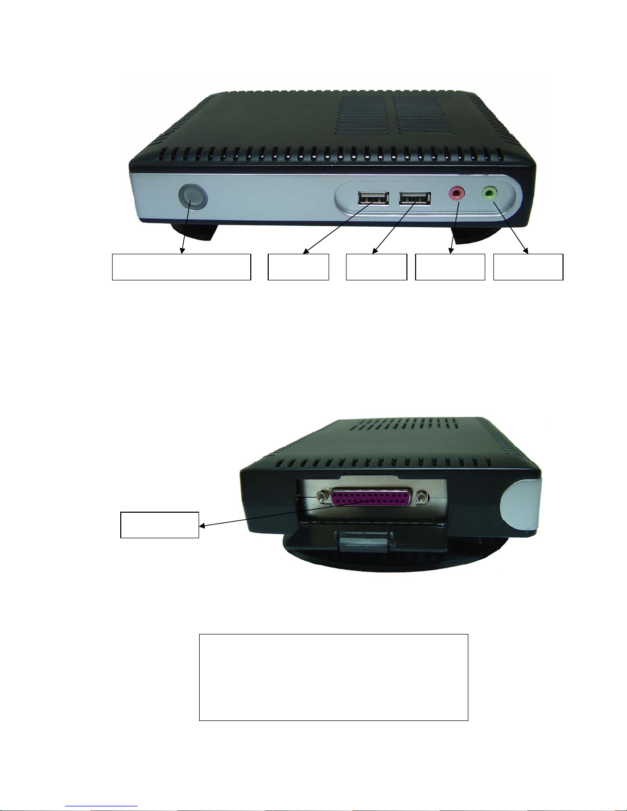
Power Switch & LED USB 1 MIC SPEAKER USB 2
2.4.2 Connector Descriptions
Power Switch
The Power Switch key to turn ON/OFF the WBT.
Audio output Connector
This connector is used to connect to an outward speaker.
Micro phone input connector.
PARALLEL
Parallel Port Connector
This connector can be used for a printer connection.
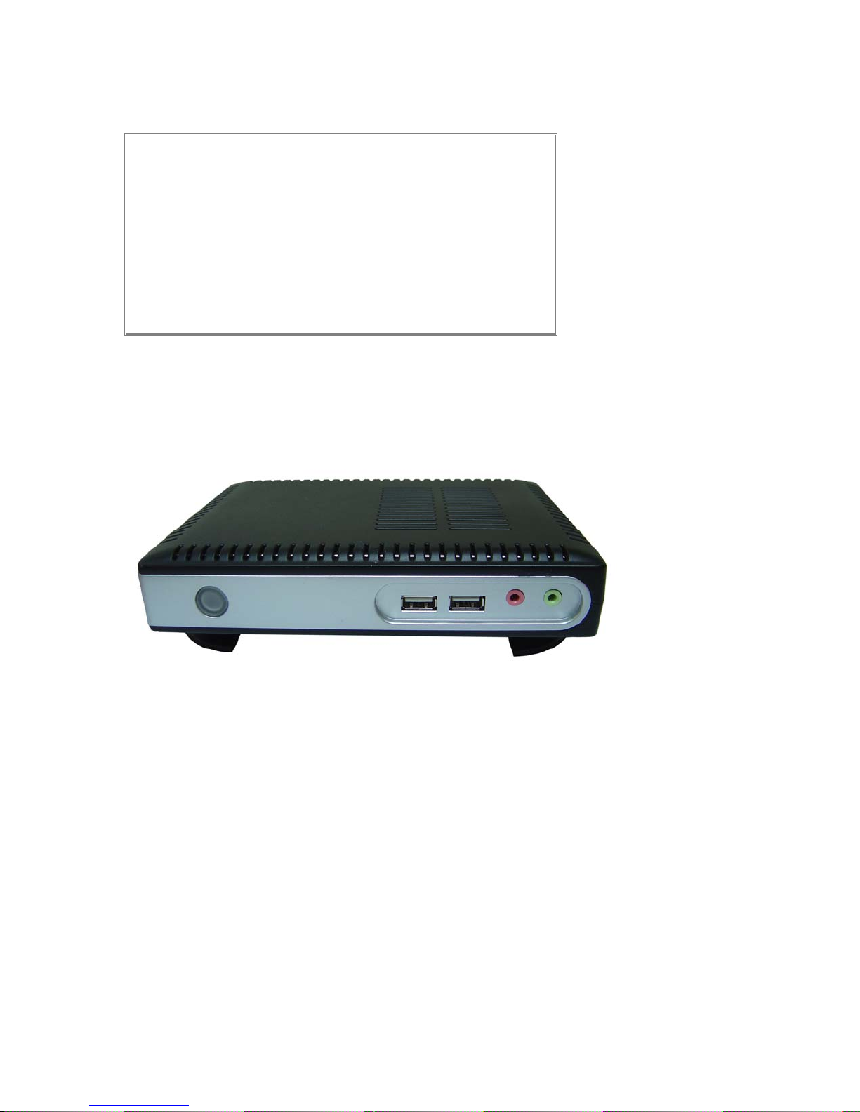
Please use foot stand properly in order to make better
____________________________
ADDS 5300 Win CE
CAUTION
thermal performance as thin client is kind of fanless
solution, especially at horizontal position. Do not put
any substances to influence venting holes function.
7
Page 13
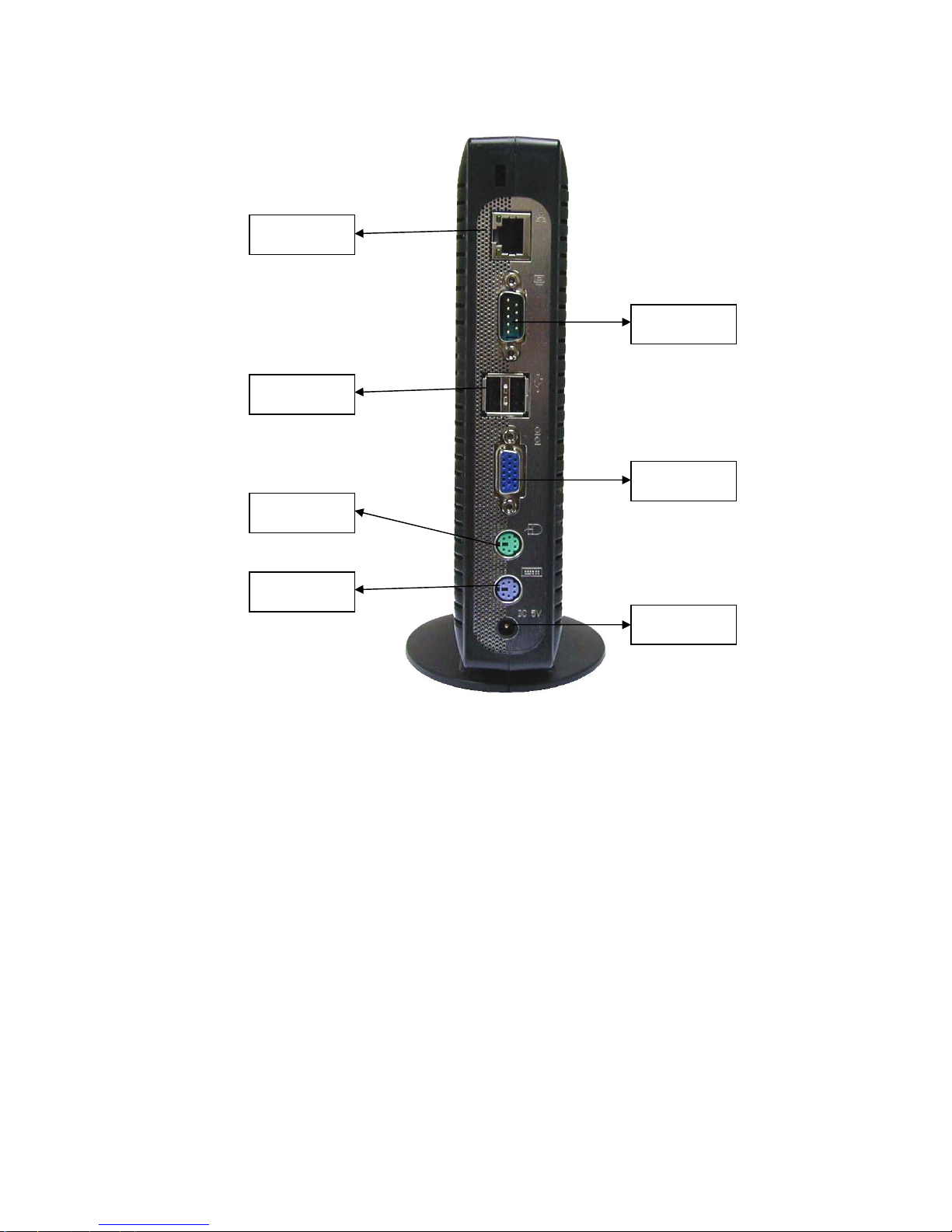
LAN
USB 2.0
Mouse
SERIAL
VGA
Keyboard
DC
RJ-45 Network Connector
This connector can be used to connect the built-in 32-bit 10/100-T Ethernet network LAN Controller to a host or Hub.
Serial Port Connectors
These connectors can be used for the serial device such as a modem device.
USB 2.0 Port
These connectors can be used for the USB devices.
VGA Connector
This connector is for displaying on a standard VGA compatible device.
PS/2 Mouse Connector
This connector is for a mouse using a PS/2 plug (mini DIN).
PS/2 Keyboard Connector
This connector is for a standard keyboard using a PS/2 plug (mini DIN).
Power Connecto r
This connector is for connecting the power cord with the terminal and the DC Adapter
.
____________________________
ADDS 5300 Win CE
8
Page 14

Before you use the CE6.0…
1. Get the device and Boot loader ready
2. The differences between CE5.0and CE6.0
z Only one user interface style supported
a. The CE6.0 does not provide WBT Mode because the Desktop Mode is more popular.
b. CE6.0 does not provide Setup Wizard because the Desktop Mode is easier to use than use Setup Wizard.
z More device drivers have been supported in CE6.0
z More complete and user friendly interface have been supported in CE6.0
a. Hot Key supported
The CE6.0 adds more Hot Keys supported than CE5.0, etc, F12 (user mode switching),
User can change the background from files, or set another kind of appearance he wants.
CE6.0 supports USB Storage device read/write function in Start Menu // Program s/ /M y USB Storage Device.
USB Manager provides the user to set the USB storage device read/write access control.
System Info v1.0 adds a new page called Component that lists the version of each component,
User Security Control is an important and new function; it provides the system manager to
a. Add/Remove is a new function; it supports the user to install the application or driver he wants to use,
ALT+F2 (Control Panel), ALT+S (Shutdown).
b. Background & Appearance change
c. USB storage Data Editor
d. USB Manager
e. System Info
And the General page adds an item display the firmware name.
z User Access and Security Control
a. Administrator/User Mode switch
The function supports the user mode switching to provide two modes for user to set
Their security controlled and access controlled.
b. User Security Control
Set the access control of this thin client for user mode or administrator mode,
It makes the thin client more complete and safe in personal security.
z Add/Remove Component
And user also can uninstall them by using the application.
z Image Update/Back-up
a. The CE5.0 OS could be upgraded to CE6.0 by using FTP Update.
b. The CE6.0 has only been installed to TK-3550, TK-3750, TK-3770 and TK-5770.
c. FTP Update v3.0 supports more kinds of data to update, user can update BIOS/firmware/logo/registry/boot
loader/company information by it,
d. FTP Update v3.0 supports files Back-up function, user can clone these kinds of file from client to serv er.
____________________________
ADDS 5300 Win CE
9
Page 15
3 Introduction of main User Interface
3.1 Desktop
Boot the device
When you push the power button to start the thin client, the device is started with BIOS first; the boot logo will be showed
When bios initial is done, and then it wills entry CE desktop mode finally.
CE6.0 is based on XP-like Desktop mode, and add our special function items on it to help the user using easier.
Desktop
3.1.1 Items on Desktop
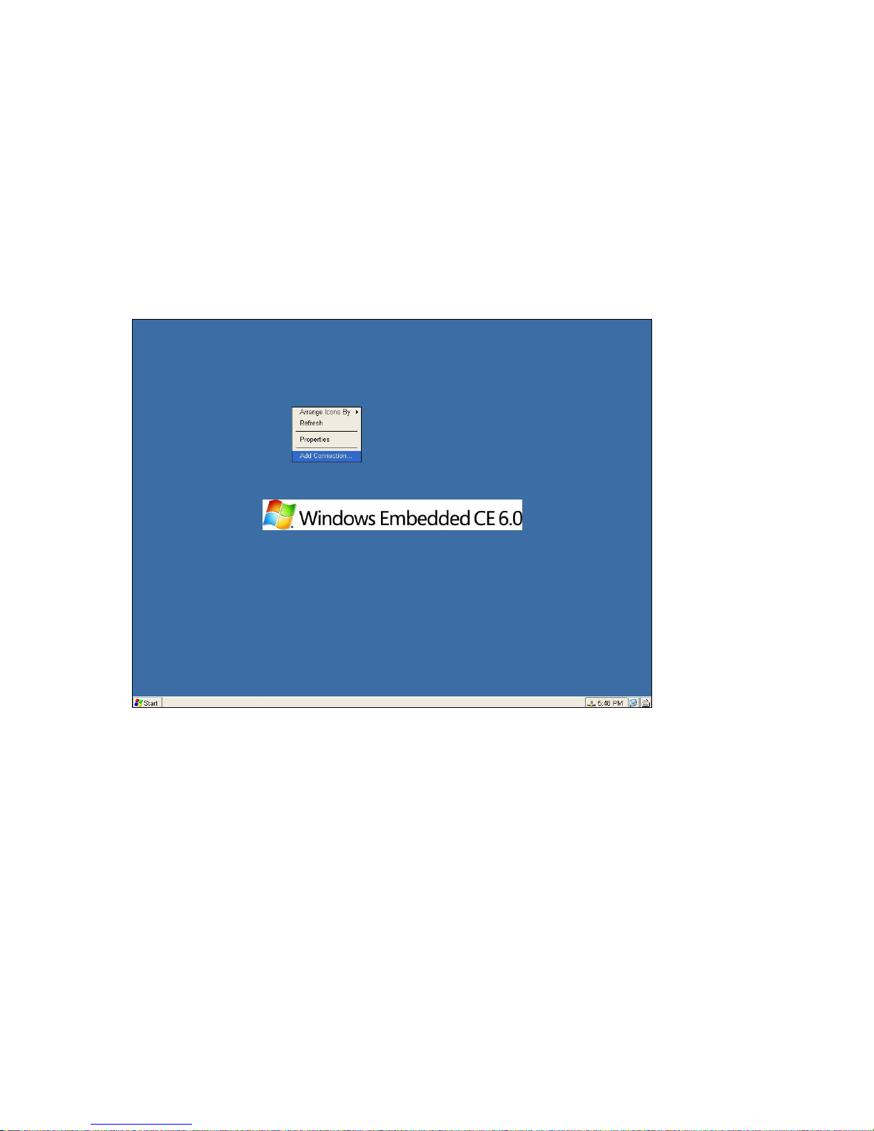
Left-Click on the Desktop will show the menu of Desktop Configuration.
Arrange Icons By
User can select the arrange mode of shortcut, the shortcuts can be arranged by Name/Size/Date/Auto Arrange.
Refresh
Refresh arrange of shortcut on Desktop.
Properties
User can open the Display Configuration page, and can set the display settings.
Add Connections
User can open the Add Connections page; can add the connections on desktop.
____________________________
ADDS 5300 Win CE
10
Page 16
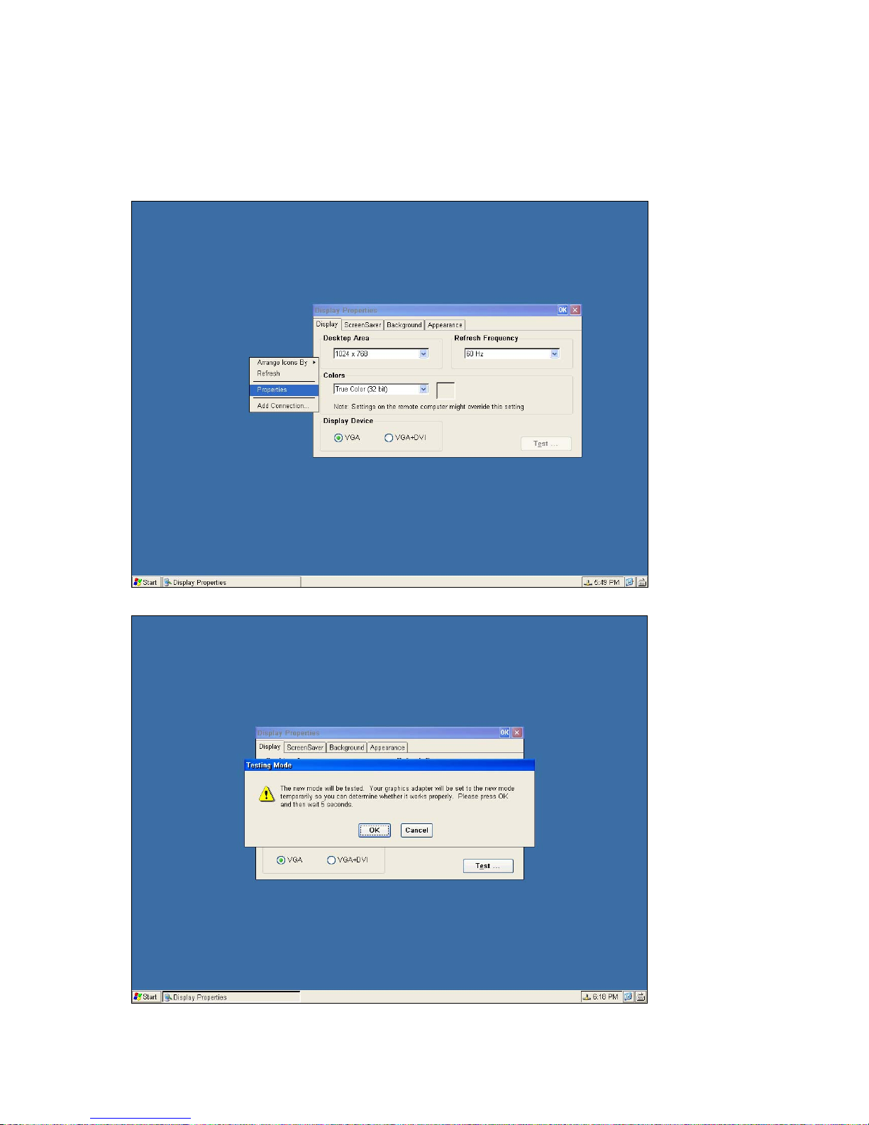
3.1.2 Properties
Alternative Display Settings
The monitor support several kinds of resolutions. If you want to test it, choose the desired resolution from the list box and
click Test.
Desktop Area and Refresh Frequency
If the screen image tests OK, the monitor will support the selected resolution.
____________________________
ADDS 5300 Win CE
11
Page 17
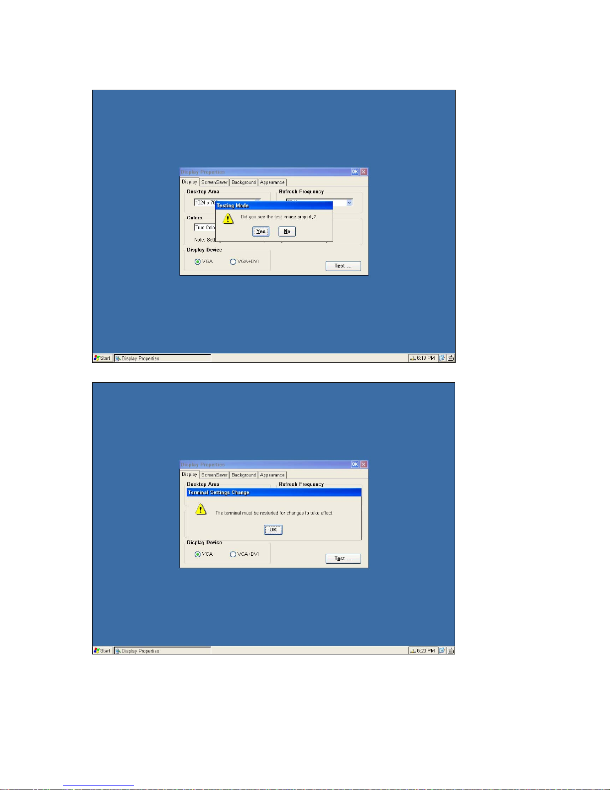
After the system implement testing new mode as user set up.
The system will notify user “did you see the test image properly”.
The Device will be rebooting to make the display settings changed actively.
____________________________
ADDS 5300 Win CE
12
Page 18
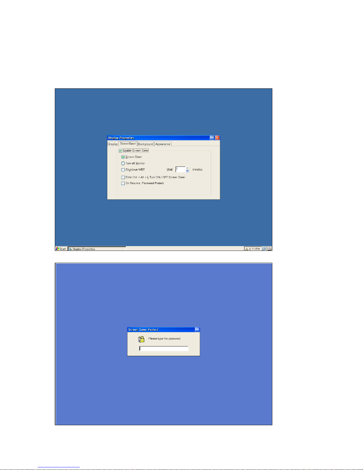
Screensaver
Tick the “Enable Screen Saver” and you can configure your desired way to enable the screen saver for this WBT. There are
three options to choose: Screen Saver, Turn Off Monitor and Turn Off WBT. You can leave this WBT to activate the function
automatically according to the time you set. Or you can tick “Enable Ctrl + Alt + L Turn ON/OFF screen saver” to manually
activate/deactivate any one of the left three energy savers you tick by pressing the hot-keys of “Ctrl+Alt+L”.
There is still one hidden option of “Enable Property Password” to gain more security protection. To have this option available
you have to click “Control Panel” tab and double click on Security tab. Please refer to the description.
User can set On Resume, Password Protect to get protect.
____________________________
ADDS 5300 Win CE
13
Page 19
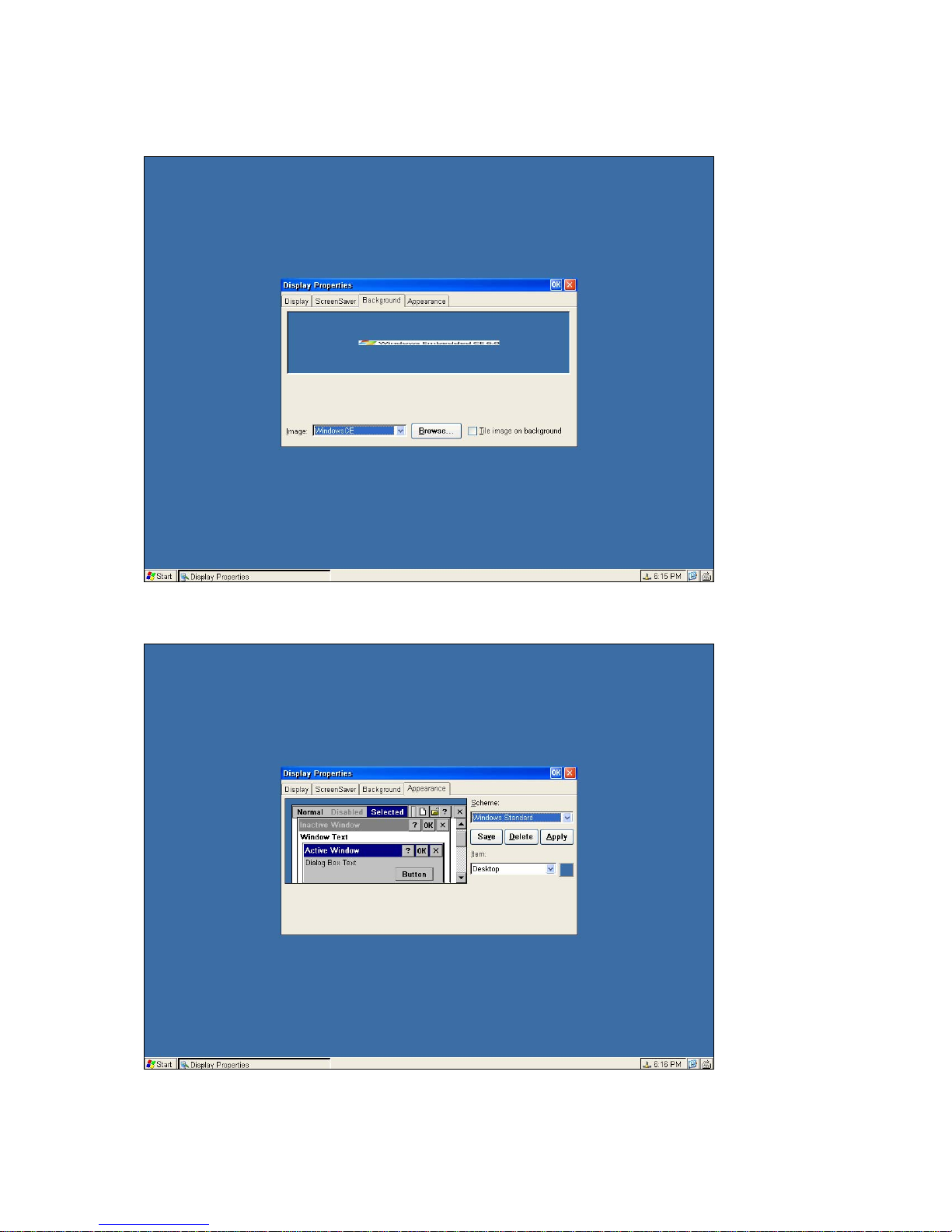
Background
Background provides user to change the background with graphic files.
User also can set the background to Tile image on background.
Appearance
User can set the appearance by change Scheme.
____________________________
ADDS 5300 Win CE
14
Page 20
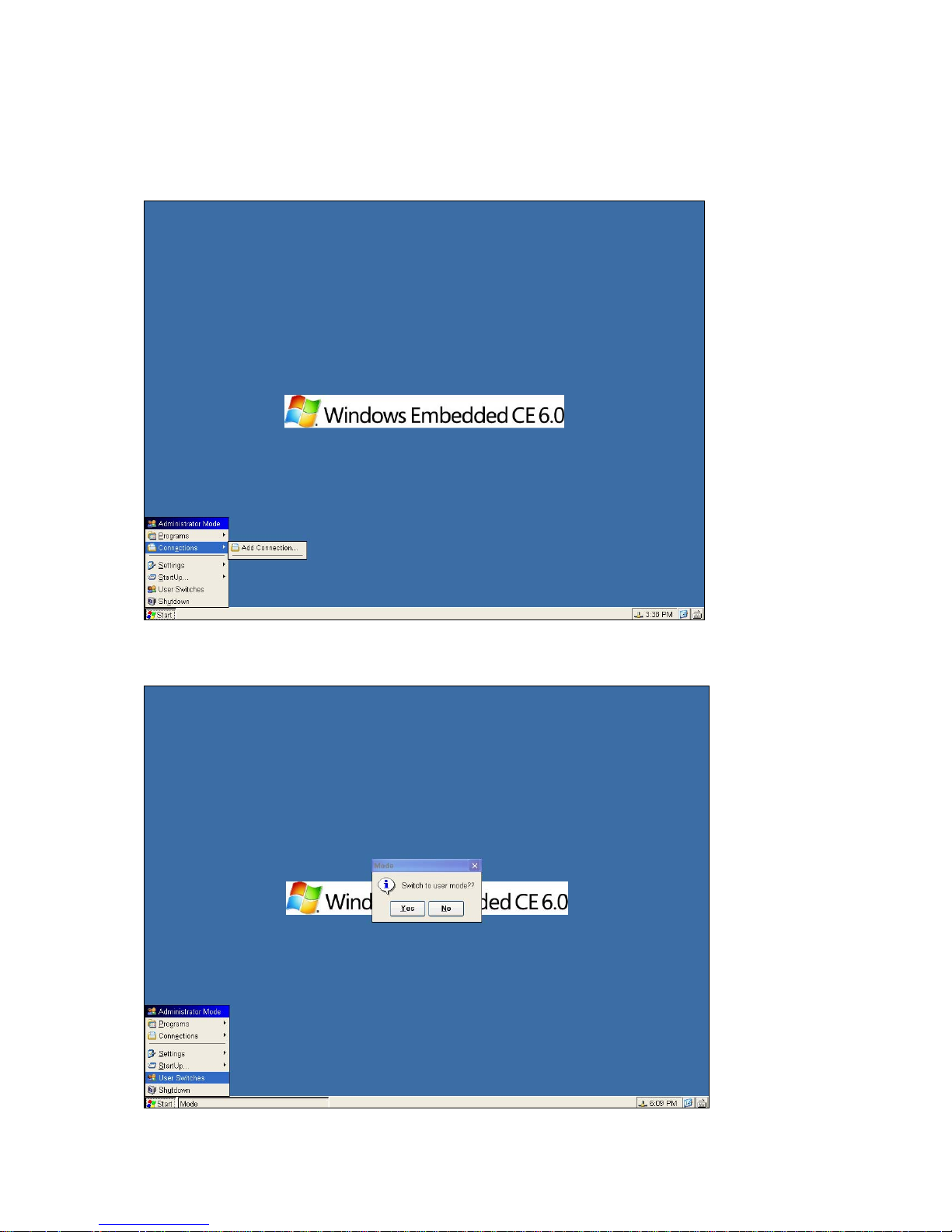
3.2 Start Menu
Start Menu is a set of all functions; it supports the user to set the client.
It has included these main items: Administrator/User mode, Programs, Connections, Settings, Start Up,
User Switched And Shutdown.
3.2.1 Administrator/User mode
It has been showed according to which user access mode you set.
User can press User Switches or F12 to switch two modes.
____________________________
ADDS 5300 Win CE
15
Page 21
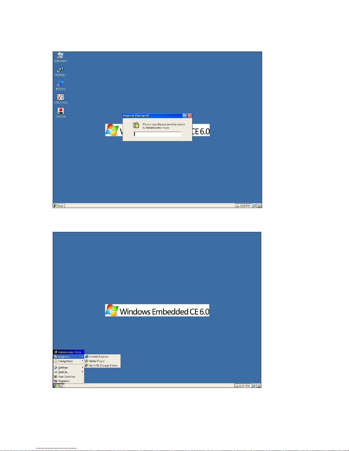
Password entered is necessary to switch from user to Administrator, and the default password is 0000.
If the user switches from Administrator to user, it doesn’t need to enter password.
3.2.2 Programs
It provides the user to use the application embedded such as Media Player/Internet Explorer/My USB Storage Device.
It also provides the user to use the application installed by add/remove.
____________________________
ADDS 5300 Win CE
16
Page 22
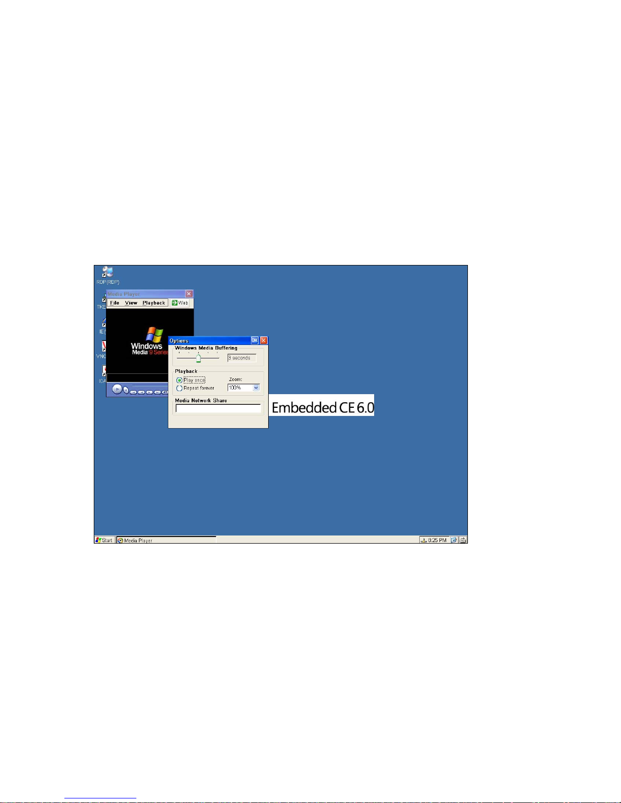
Microsoft Internet Explorer
Connects to the Internet directly via embedded Internet Explorer. Refer to chapter 4.7 for the Internet applications.
Microsoft Media Player
An applications winch you can connect to play a media & set the option in your WBT. Refer to chapter 4.8 for Media Player.
(1) Windows Media Buffering: select the buffer 1seconds <-> 5 seconds
(2) Volume: You can set the volume when playing the media and select the sound is mute or loud.
(3) Playback: Select Play Once when you want to play a time. Or select Repeat Forever when you want the media
repeat to play.
(4) ZOOM: If the Enable Full Screen is enable .You can see the media is played in full screen mode. You can also
select the windows size when the media starts to play. And press ALT + ENTER or ESC to switch between full
mode and general mode.
(5) Play Default Media Files: You can set which file will be played .The Play lists means the recent media which be
played. The Favorites displays the media files, which you add to my favorites in media player. And if you want to
type a media file name and path by yourself. You can select Edit Define.
____________________________
ADDS 5300 Win CE
17
Page 23
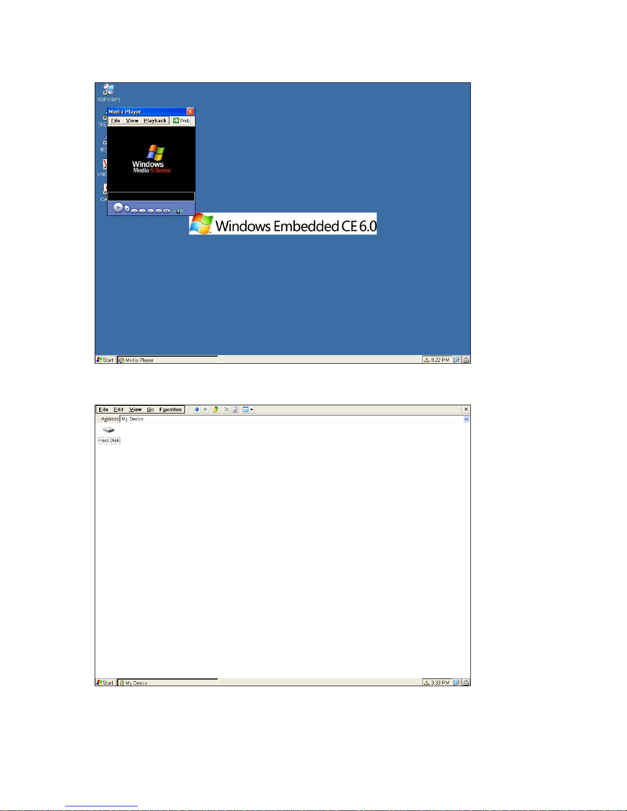
To start this application simply double click it. If your settings have been correctly set up then this is going to work.
My USB Storage Device
User can edit the USB storage device installed by this tool.
3.2.3 Connections
____________________________
ADDS 5300 Win CE
18
Page 24
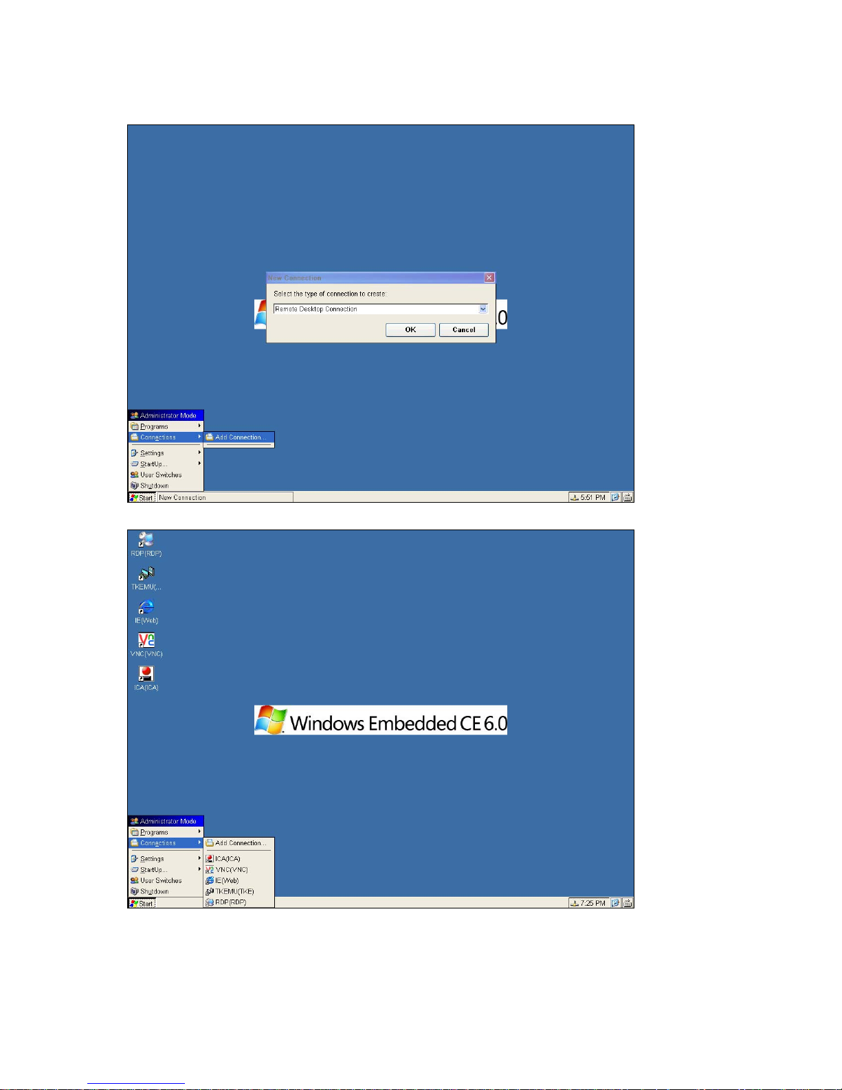
User can open the Add Connections page by pressing Add Connections.
Added connections will be list on this item and desktop.
3.2.4 Settings
____________________________
ADDS 5300 Win CE
19
Page 25
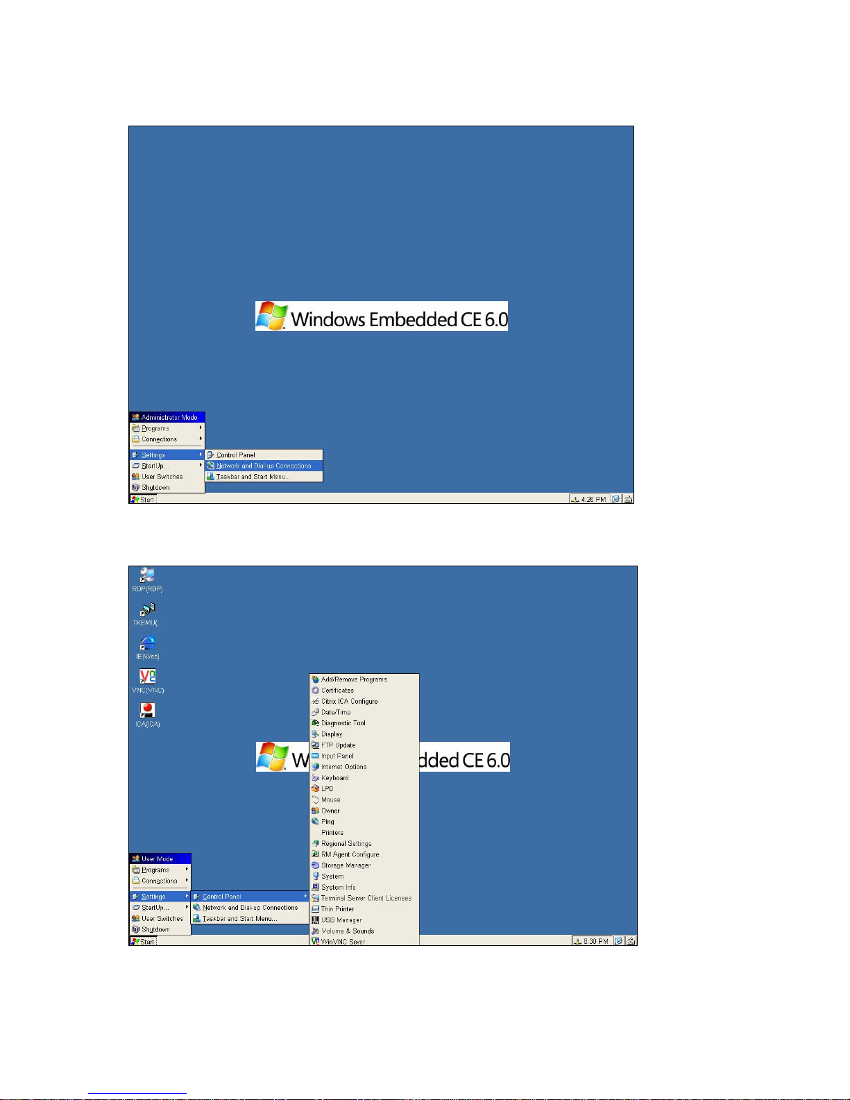
It provides user to set the terminal properties by Control Panel, Network and Dial-up Connections and
Taskbar and Start Menu.
Control Panel
The Control Pane l properties sheet lets you configure your terminal’s function.
User can set it to display by Expand mode or open a new window.
Network and Dial-up Connections
____________________________
ADDS 5300 Win CE
20
Page 26
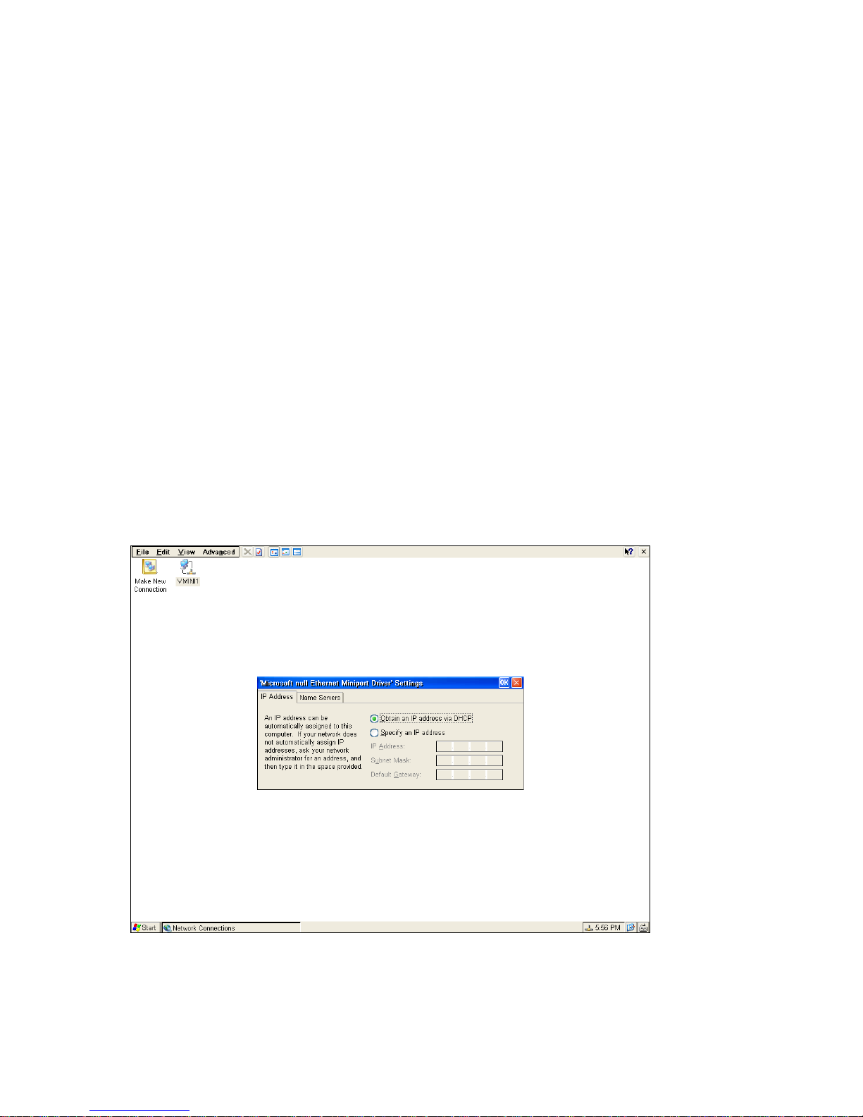
Network Configuration
The Network and Dial-up Connections properties sheet lets you set up a method for SNMP upgrades. Invoke this
properties sheet by clicking on the Network and Dial-up Connections tab in the Settings item. The following figure shows
the Network and Dial-up Connections properties sheet. If you have a DHCP server, then click on Obtain an IP address
from a DHCP server to automatically get an IP address. Or you may specify an IP address by yourself. You can also type a
Name for the Terminal
.
Network attached device must contain a unique network identifier. If the network is using TCP/IP as a communication
protocol, these identifiers are called IP addresses. The following series of screens will allow you to choose from two different
methods of assigning the IP addresses.
Use the IP information supplied by DHCP
If your network provides DHCP (Dynamic Host Configuration Protocol) service and you want it to provide the terminals IP
information, leave the first option selected.
The terminal can get its IP address through a DHCP service by default. The DHCP will automatically assign an IP address
that is drawn from a pool of available IP addresses, when a terminal unit is powered on and a request is broadcast over the
network.
Use the IP information supplied by DHCP
If you need to specify static IP address for the terminal, select the second option.
The option is selected automatically if your network does not provide a DHCP service, or if the unit is not properly connected
to the network. In these cases, leave the second option selected.
DHCP
Note: If your network does not provide a DHCP service but you get the screen shown above, make sure the terminal unit is
properly connected to the network. Then restart it by cycling the power off and then on.
Specify a static IP address
____________________________
ADDS 5300 Win CE
21
Page 27
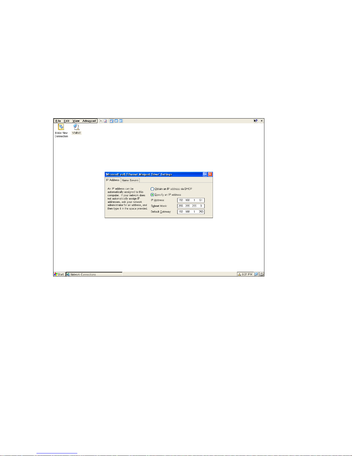
If the method you selected on the prior screen was to enter a static IP address, the below screen will appear. You will be
required to enter the following information onto the screen.
IP address
Required for identifying this unit to the network. The format will follow the standard addressing format.
Subnet Mask
Required for designating which network the IP address is a part of.
Gateway
Optional address which identifies the machine through which a subnet communicates with another network.
Specify an IP Address
Enable/Disable Name Resolution Services
____________________________
ADDS 5300 Win CE
22
Page 28
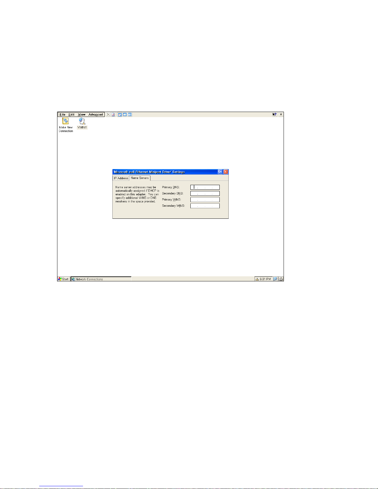
The screen shown below will appear only if you choose the Static IP Addressing method. The DHCP method will provide this
information required using a name resolution service.
Terminal servers typically support both DNS (Domain Naming Service) and WINS (Windows Internet Naming Service) name
resolution services. This screen allows the terminal unit to use one or both of these resolution services. To enable DNS,
WINS, or both, check the corresponding box. In the text boxes, enter the following information as appropriate for
DNS, WINS, or both, check the corresponding box. In the text boxes, enter the following information as appropriate for each.
Click Next.
Make a new type connection
____________________________
ADDS 5300 Win CE
23
Page 29
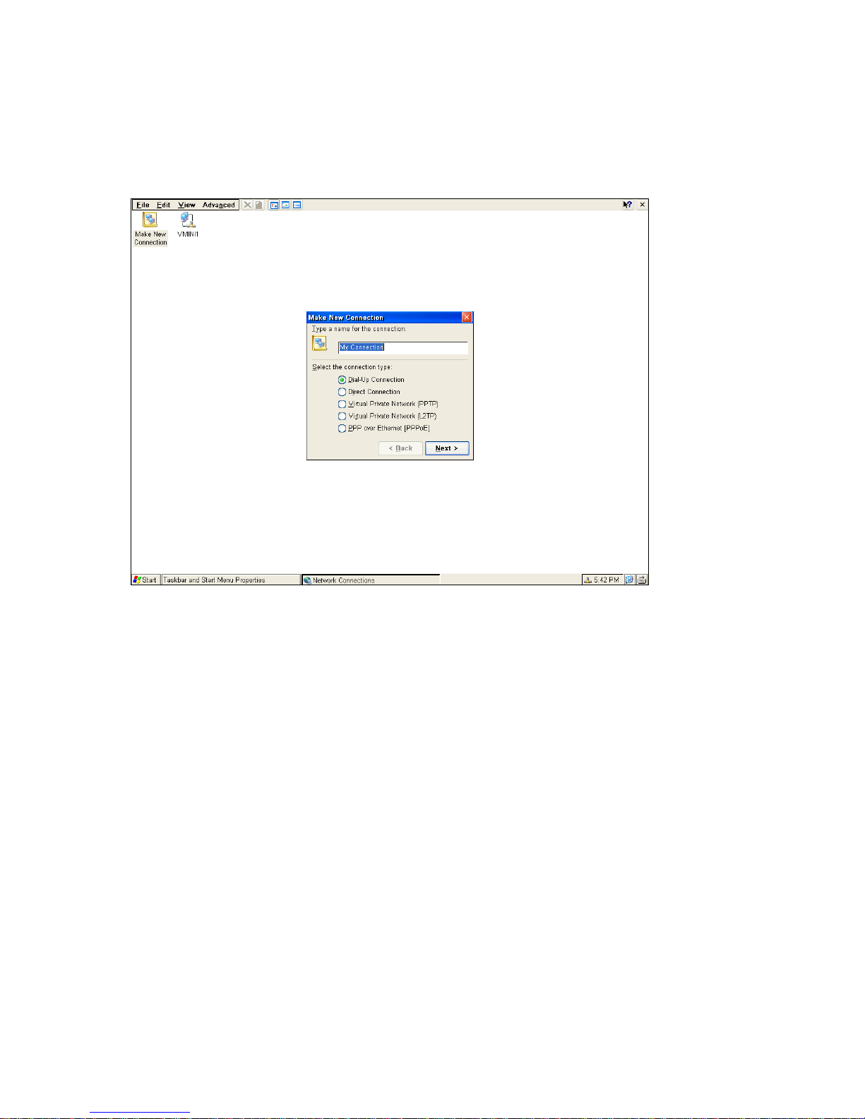
Choose the connection type by clicking on the radio button. It will decide which connection you want to connect with a server.
Three options are available:
Choose Dial-Up Connection radio button if you desire to connect with the server through the modem; Or select Direct
Connection radio button to connect with the server through serial port RS 232;
Or select Virtual Private Network (PPTP or L2TP) radio button to build a VPN connection. Here we choose “Dial-Up
Connection”; Or select PPP over Ethernet to build a PPPoE connection, then click on Next.
Make New Dial-Up Connection
____________________________
ADDS 5300 Win CE
24
Page 30
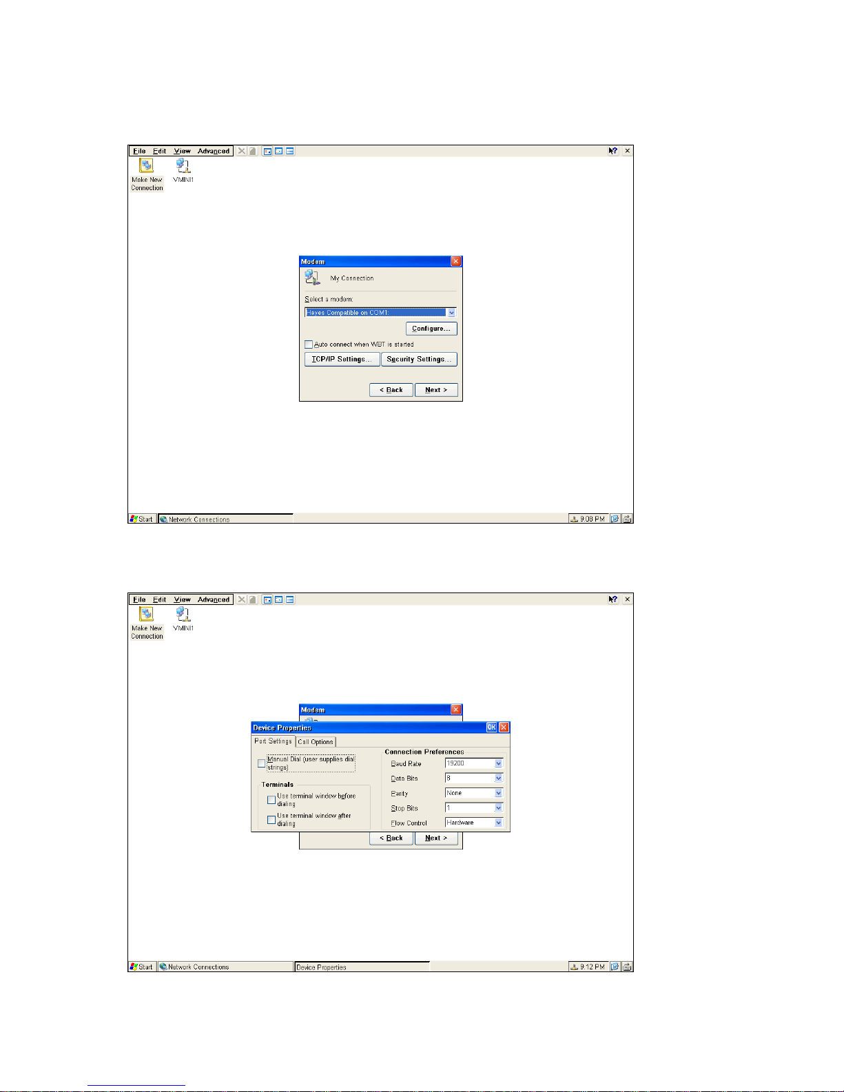
The Make New Dial-Up Connection dialog should now appear. Select the serial connection for the current COM port being
used for the connection. Then click on Configure…
Device Properties
Port Setting
The Device Properties dialog should now display. Select the Port Settings tab and set the connection preferences (Baud
Rate, Data Bits, Parity, Stop Bits, Flow Control) to match the host.
Call Options
____________________________
ADDS 5300 Win CE
25
Page 31
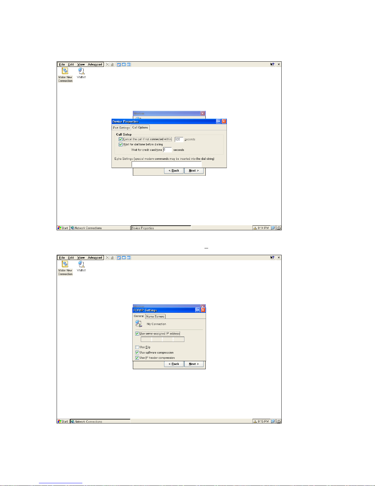
Select the Call Options tab. Select “Wait for dial tone before dialing” and deselect the rest of the options. Click “OK” when
finished.
TCP/IP Settings
From the Make New Dial-Up Connection dialog click on the TCP
the General tab. Check the Use server assigned IP address, Use software compression and Use IP header compression.
/IP Settings button. In the TCP/IP Settings dialog select
Name Servers
____________________________
ADDS 5300 Win CE
26
Page 32
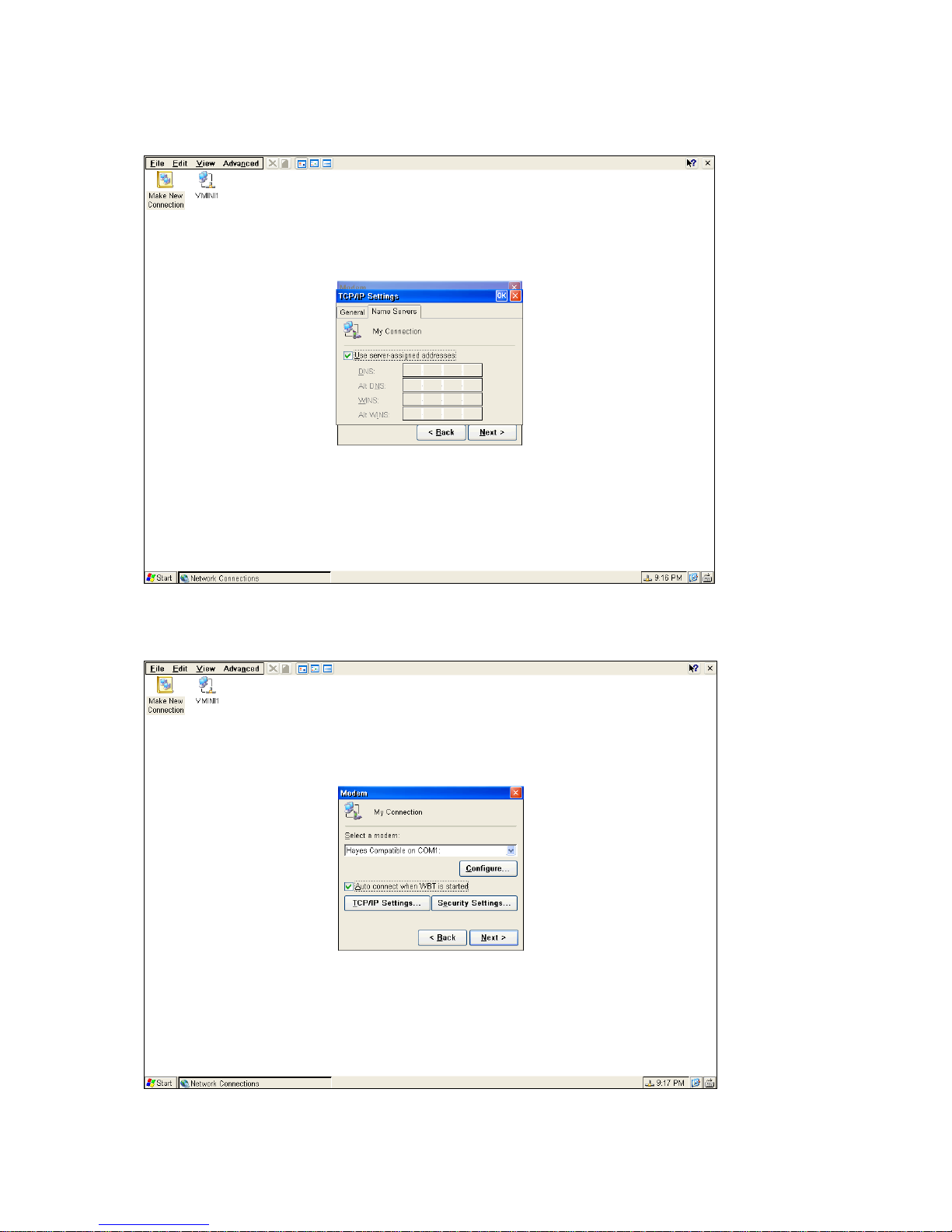
Now select the Name Servers tab. Select Use server assigned addresses. When finished, click OK. Set Primary and Second
DNS, Primary and Second WINS if you decline to use Server-assigned address.
Auto Connect when WBT is started
If it is enabled, the connection will connect automatically when booting.
Security Setting
____________________________
ADDS 5300 Win CE
27
Page 33
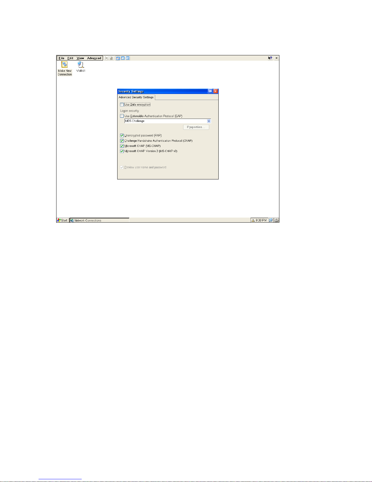
From the Make New Dial-Up Connection dialog click on the Security Settings button.
Use the Security properties sheet to access security features if you want.
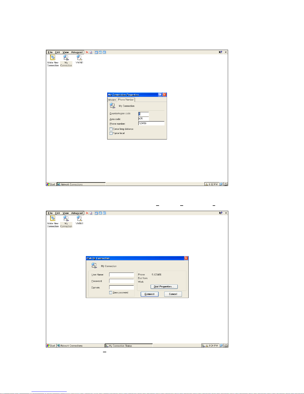
Country, Are a code and Telephone
Below the Country, Area code and Telephone number must be entered correctly in the blank area for Dial-Up Connection.
____________________________
ADDS 5300 Win CE
28
Page 34
Click “Finish” to end this dialog.
Dial-Up Connection
To start PPP Dial-Up Connection
In Connection Manager dialog box click Connections tag and select the RAS connection you would like to connect to.
The following figures will appear. You will have to enter the U
ser Name, Password and Domain to log on the connec t i on.
In this dialog you can click on “D
____________________________
ADDS 5300 Win CE
ial Properties…” to configure the Dialing Properties shown as below:
29
Page 35
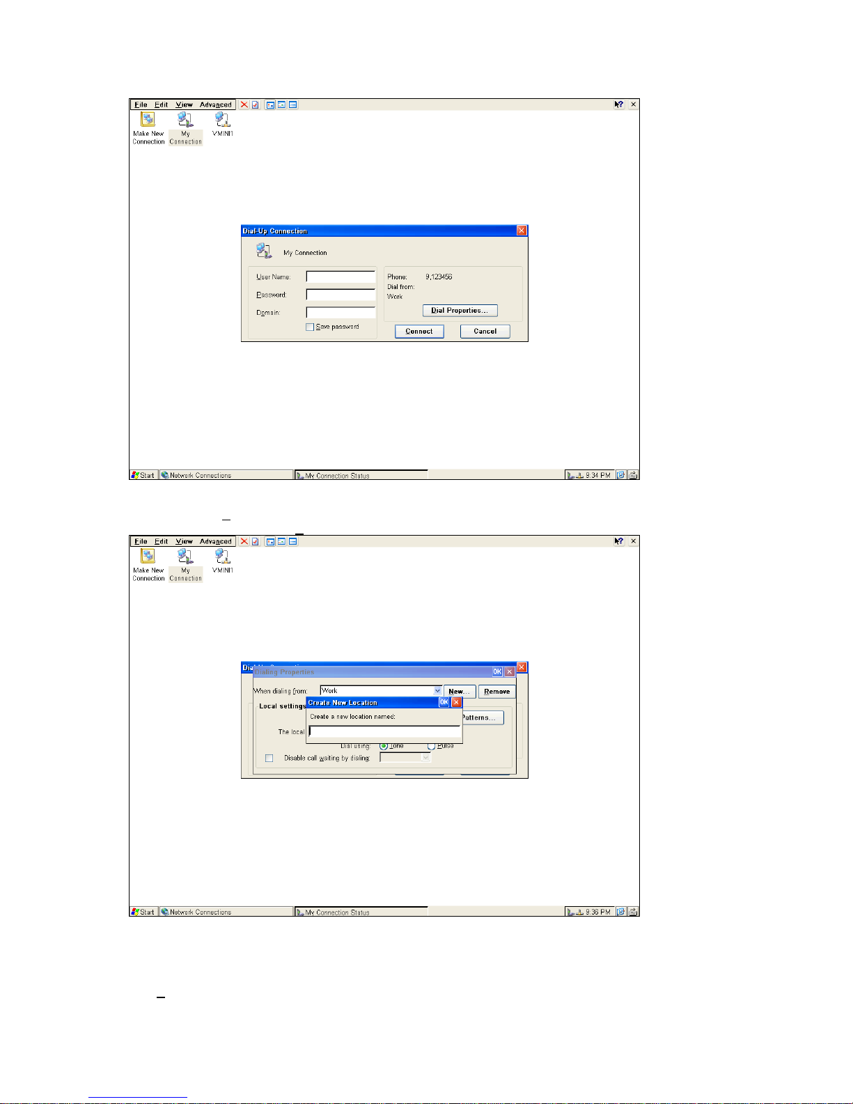
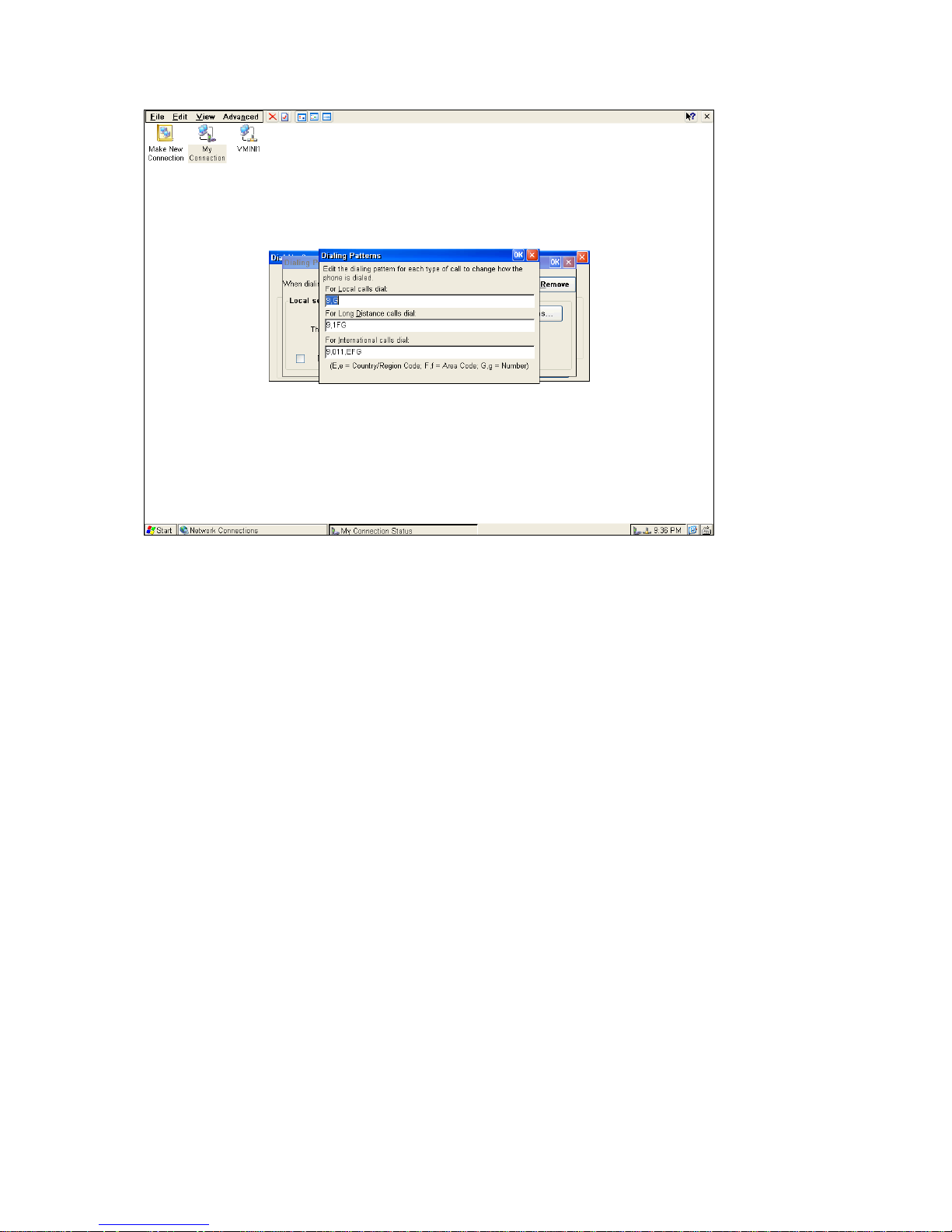
You can click on “N
added location, simply click on “R
ew…” to add a new location you would like to dial from. The figure shows as below. To delete the newly
emove”.
The “D
ialing Patterns…” dialog lets you configure the settings shown as below.
____________________________
ADDS 5300 Win CE
30
Page 36
Once everything is correctly set up, click on Connect on Dial-up Connection dialog. The target and host should now be
connected. You should see connection icons in the status bars of your host and target. Once the PPP Dial-Up is connected
successfully, then press the Hot-keys “Ctrl +Alt + End “ to back to the “Terminal Connection Manager ”and double click on
RDP or ICA for connection.
Direct Connection
Make a New Direct Connection
____________________________
ADDS 5300 Win CE
31
Page 37
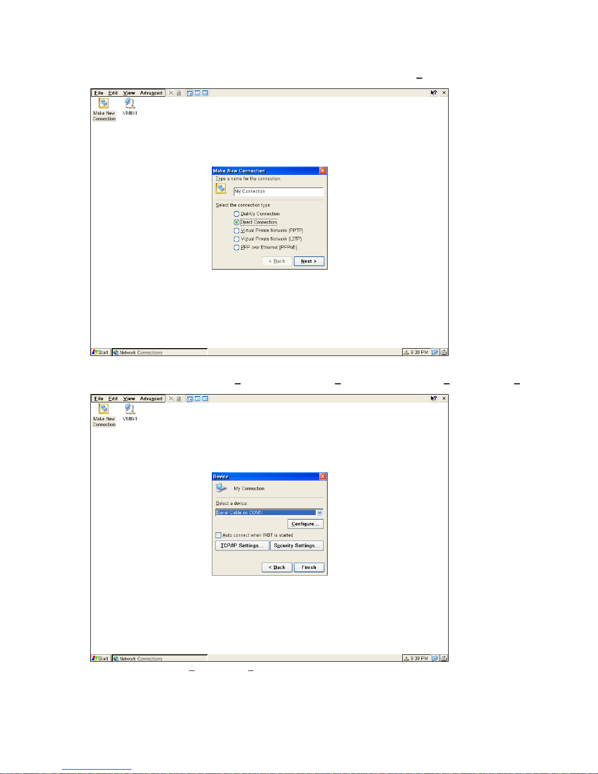
In the Make New Connection dialog select Direct Connection radio button. Then click on “Next”.
Direct Connection
The Make New Direct Connection dialog should now appear. Select the serial connection for the current COM port being
used for the connection. Then click on “C
Setting” are the same as stated in the Make New Dial-Up Connection above.
onfigure” and click on “TCP /IP Setting” .The setting of “Configure” and “TCP/IP
Click on “Finish” once the “C
back to the Configure entry of Terminal Connection Manager.
To Start Direct Connection
onfigure” , “TCP /IP Settings” and “Security Settings” have been completed. Then you will go
____________________________
ADDS 5300 Win CE
32
Page 38
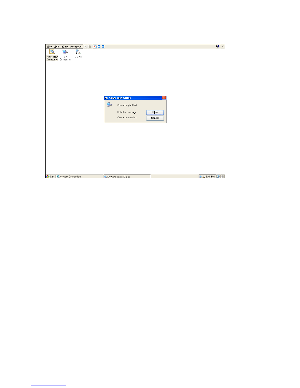
In Connection Manager dialog box click Connections tag and select the RAS connection you would like to connect to. The
figure shows as below.
The target and host should now be connected. You should see connection icons in the status bars of your host and target.
Once the Direct Connection is connected successfully, then press the Hot-keys “Ctrl +Alt + End “ to back to the “Terminal
Connection Manager ”and double click on RDP or ICA for connection.
Virtual Private Network Connection
____________________________
ADDS 5300 Win CE
33
Page 39
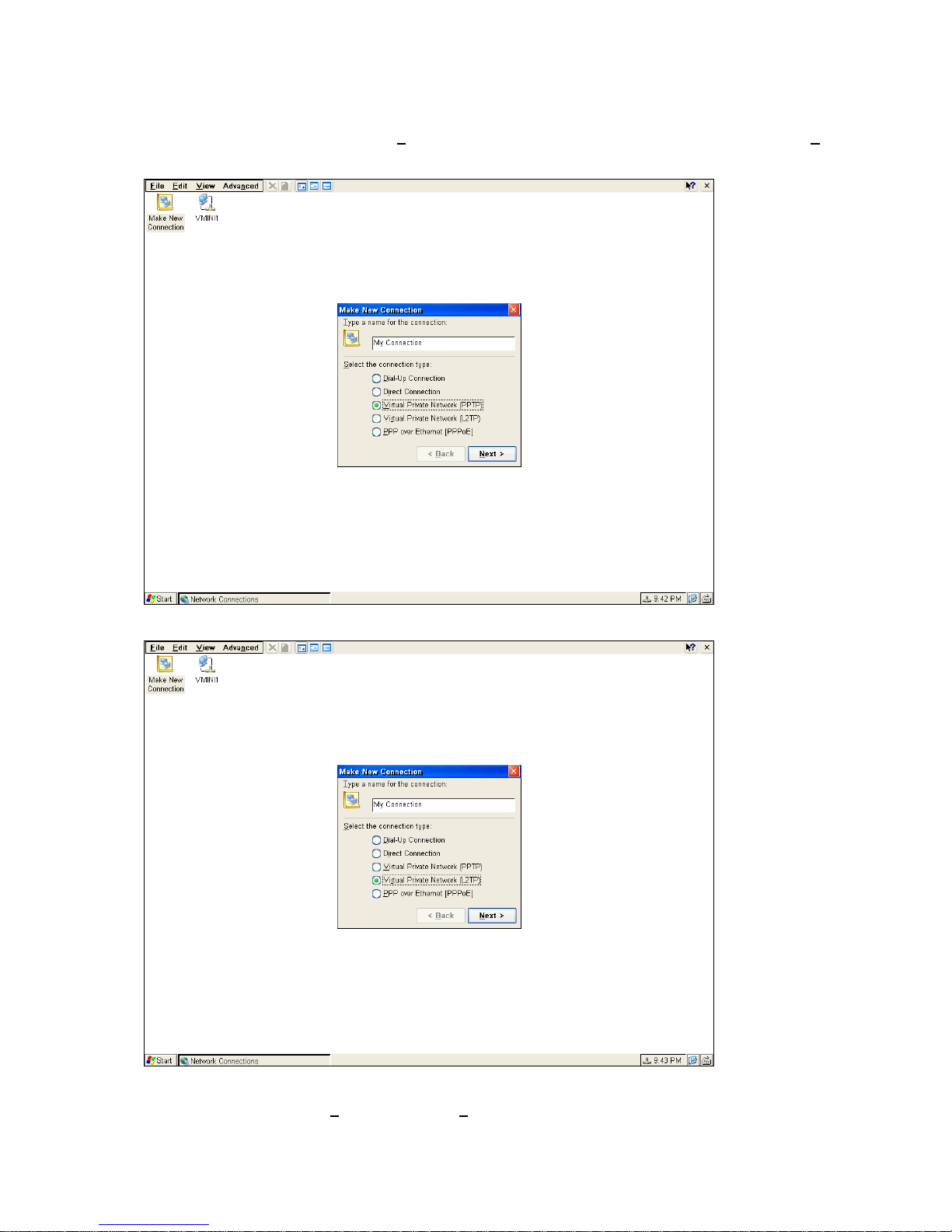
Make a New Virtual Private Network Connection
In the Make New Connection dialog select “V
(PPTP)
irtual Private Network (PPTP / L2TP)” radio button. Then click on “Next”.
(L2TP)
The Make New Virtual Private Network Connection dialog should now appear. Type in the Host name or IP address you wish
to connect to. Then click on “TCP
____________________________
ADDS 5300 Win CE
/IP Setting” .The TCP/IP Setting is the same as stated in the Make New Dial-Up
34
Page 40
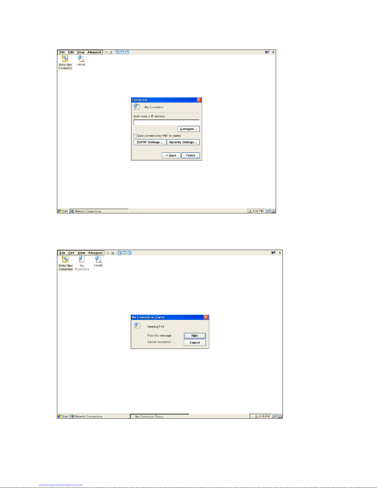
Connection above. After all done, click on “Finish” to go back to the Configure entry of Terminal Connection Manager.
To start Virtual Private Network Connection
In Connections entry of Terminal Connection Manager select the RAS connection you would like to connect to. The target
and host should now be connected. You should see connection icons in the status bars of your host and target. Once the
Virtual Private Network Connection is connected successfully, then press the Hot-keys “Ctrl +Alt + End “ to back to the
“Terminal Connection Manager ”and double click on RDP or ICA for connection.
PPP over Ethernet Connection (PPPoE)
Make a PPP over Ethernet Connection
____________________________
ADDS 5300 Win CE
35
Page 41
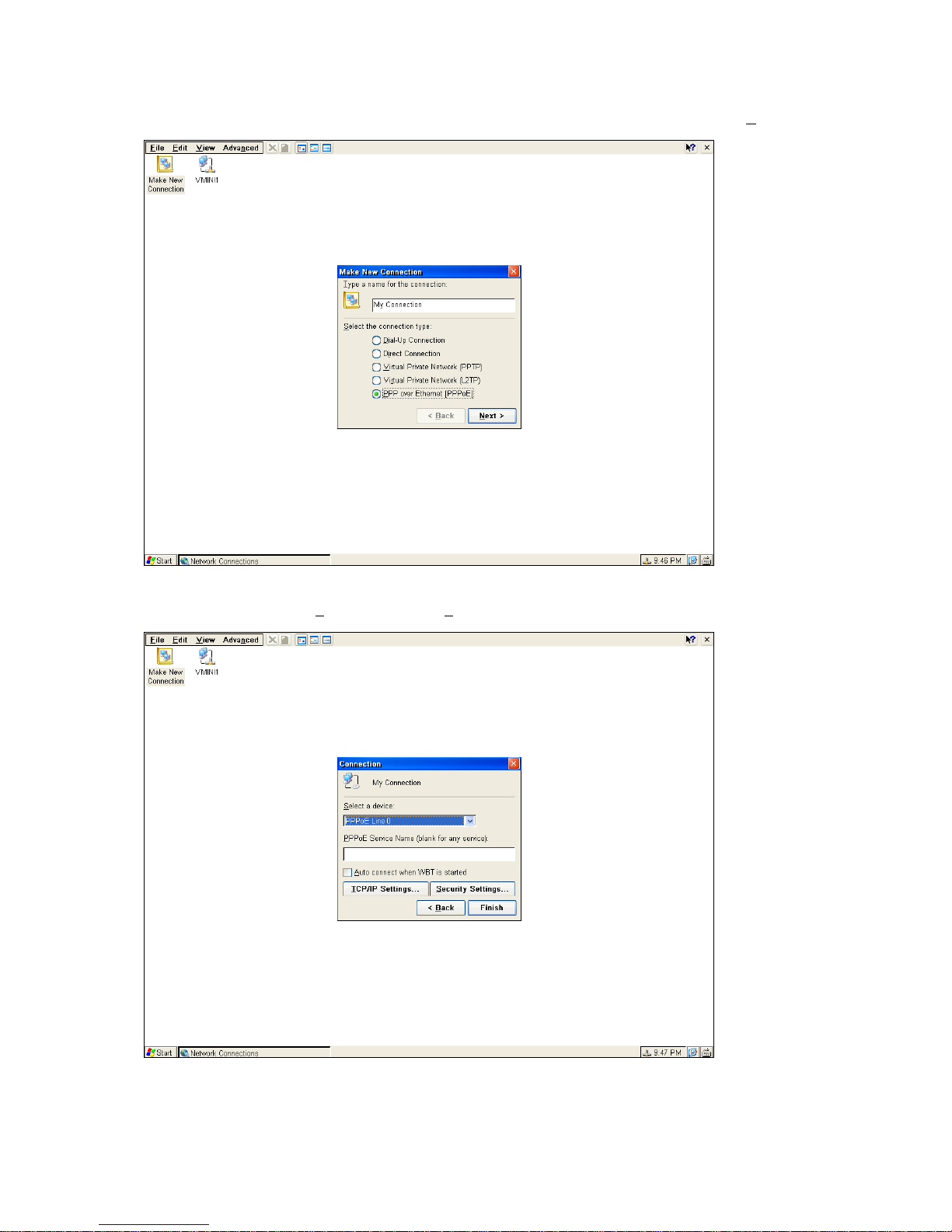
In the Make New Connection dialog select “PPP over Ethernet Connection” radio button. Then click on “Next”.
The Make New PPP over Ethernet Connection dialog should now appear. Type in the Host name or IP address you wish to
connect to. Then click on “TCP
above. After all done, click on “Finish” to go back to the Configure entry of Terminal Connection Manager.
/IP Setting” .The TCP/IP Setting is the same as stated in the Make New Dial-Up Connection
To start a PPP over Ethernet Connection
In Connections entry of Terminal Connection Manager select the RAS connection you would like to connect to. The target
and host should now be connected. You should see connection icons in the status bars of your host and target. Once the
____________________________
ADDS 5300 Win CE
36
Page 42
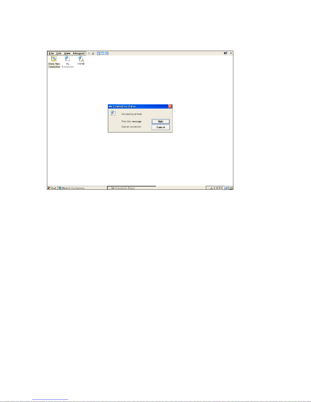
PPP over Ethernet Connection is connected successfully, then press the Hot-keys “Ctrl +Alt + End “ to back to the
“Terminal Connection Manager ”and double click on RDP or ICA for connection.
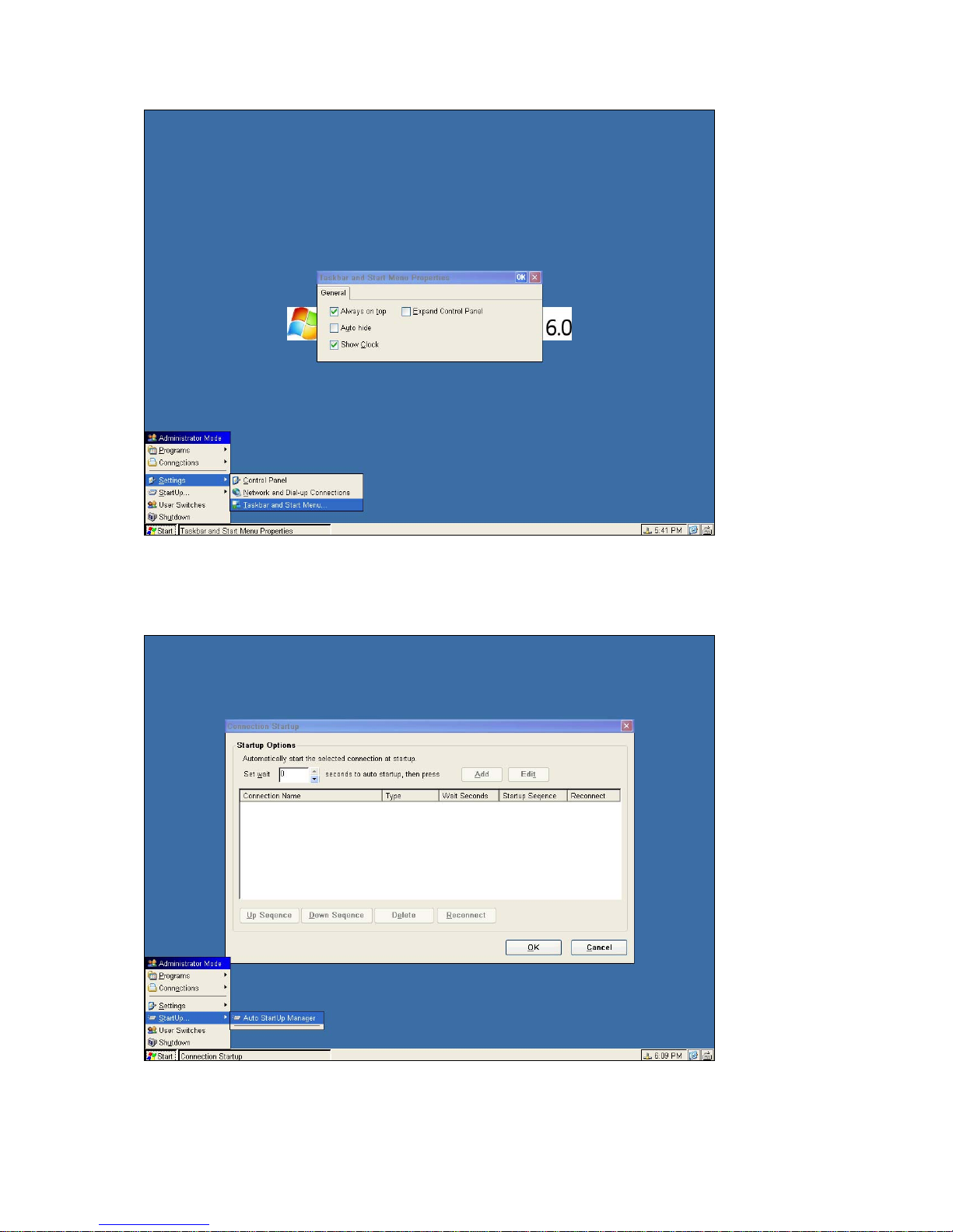
Taskbar and Start Menu
User can select the properties to set.
Always on Top
Set the Taskbar always on Top.
Auto hide
Set the Taskbar hide automatically.
Show Clock
Show the clock on Taskbar or not.
Expand Control Panel
Expand Control Panel can set the items of Control Panel listed on Start Menu.
____________________________
ADDS 5300 Win CE
37
Page 43
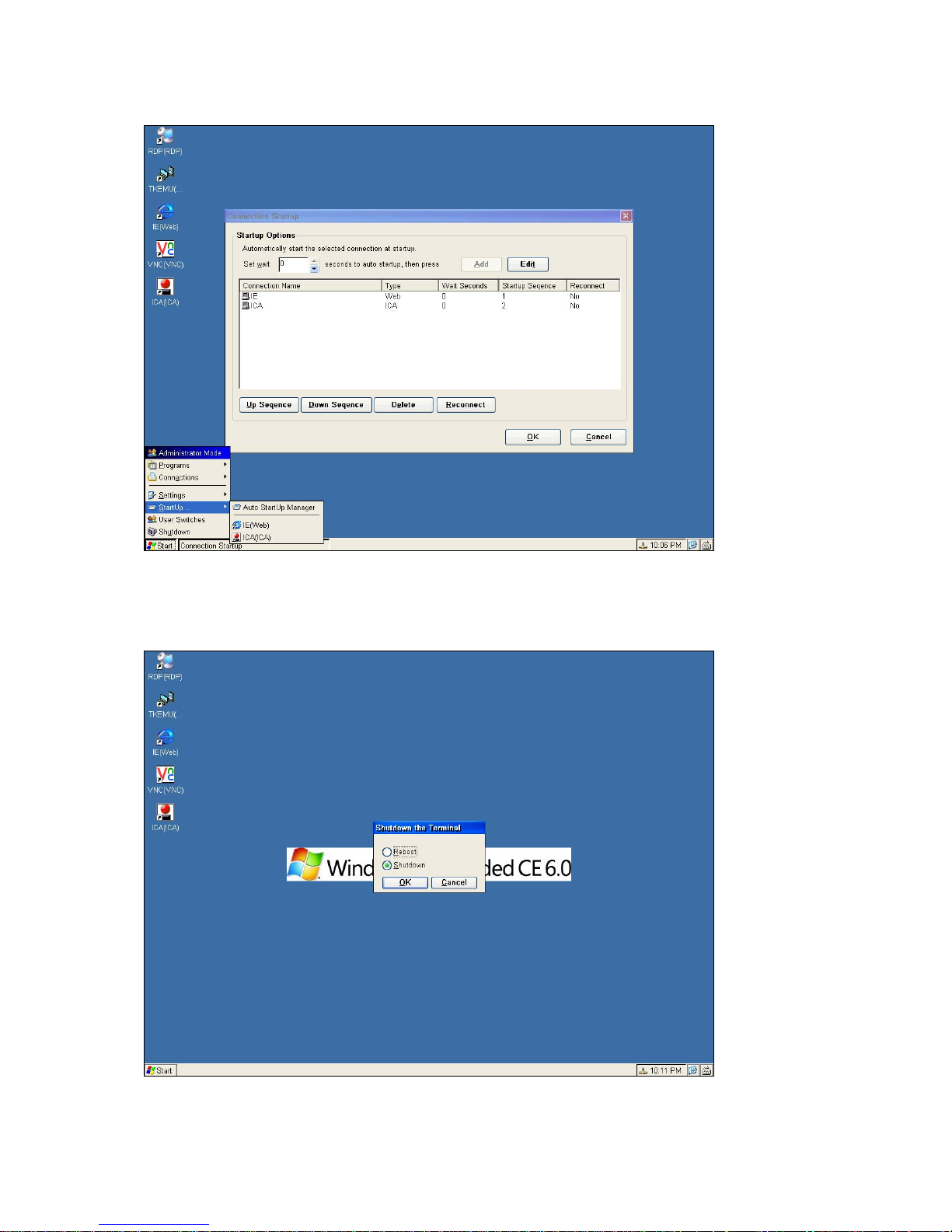
3.2.5 Startup…
Startup item provides the user to add the connections that added by Add Connections or Network and Dial-up
connections to auto run when the WBT boots.
____________________________
ADDS 5300 Win CE
38
Page 44
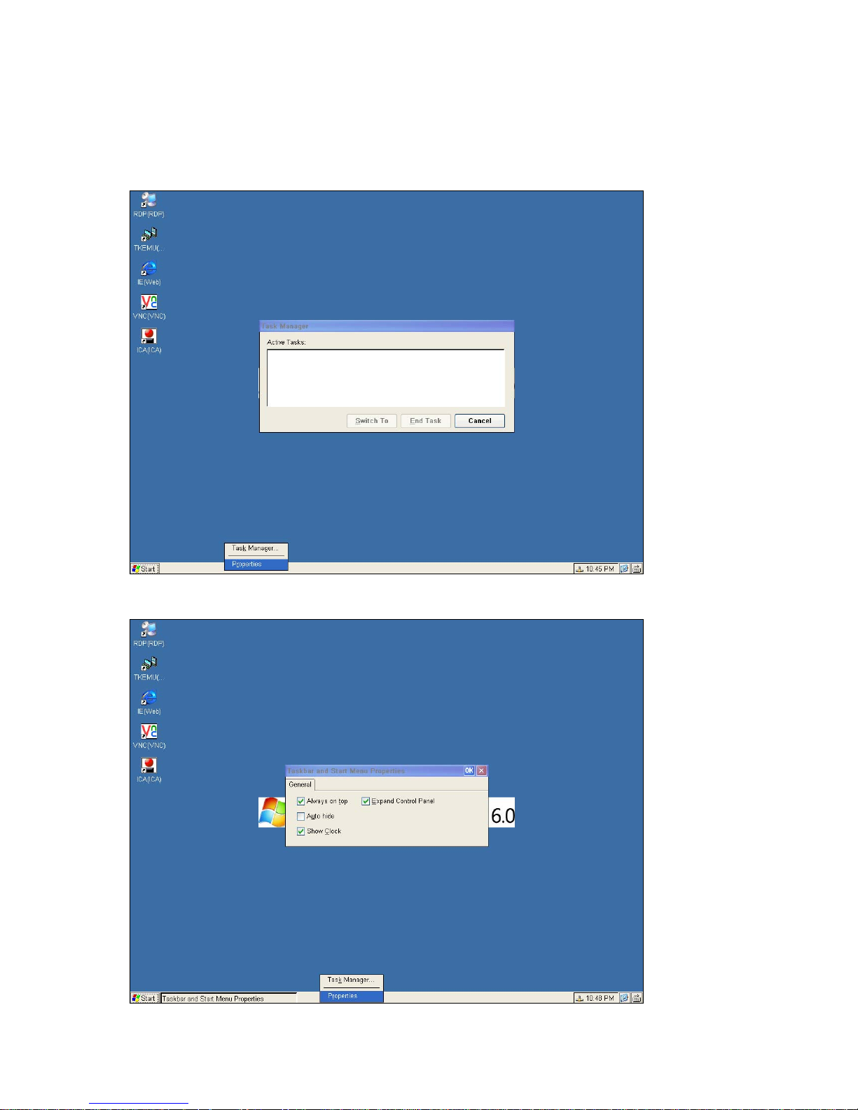
The connections, which set to auto start, will be added to this dialog list and menu list.
3.2.6 Shutdown
Press Alt + S or select the item Shutdown will appear this dialog.
User can select Reboot to re-start the terminal or select Shutdown to power down it.
____________________________
ADDS 5300 Win CE
39
Page 45
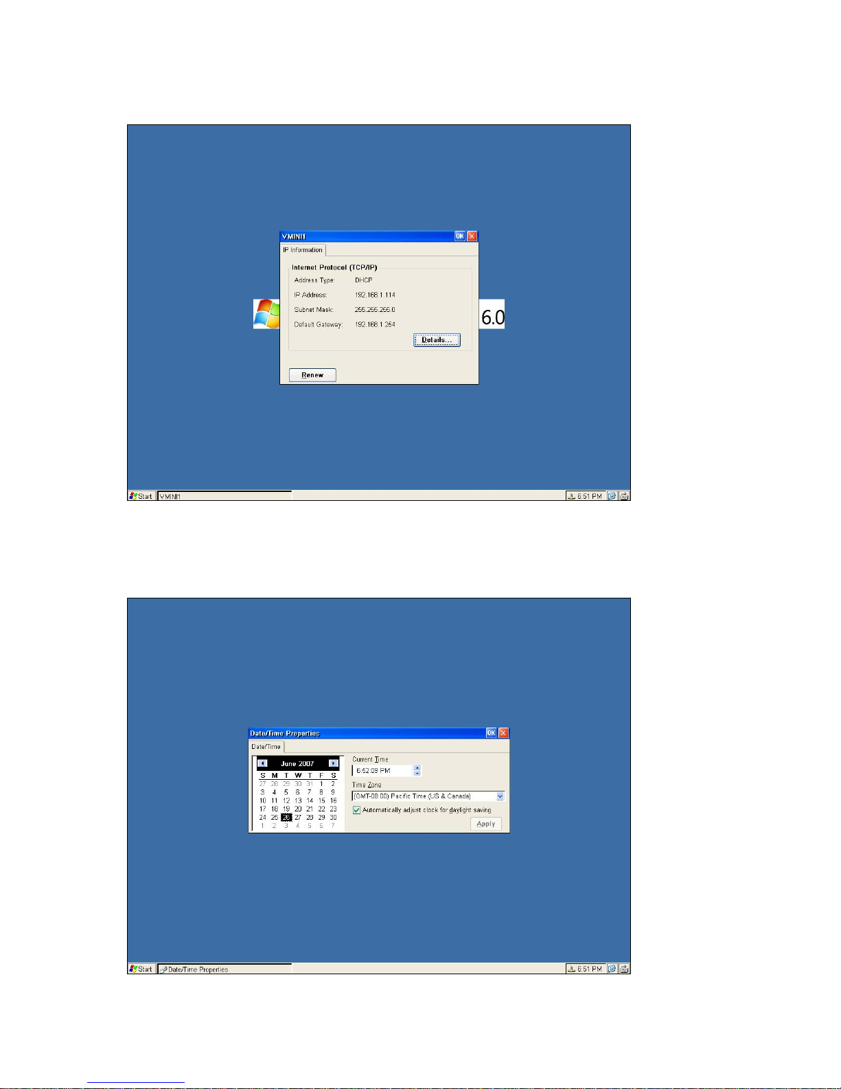
3.3 Taskbar
User can right click the mouse on Task Bar and select the properties to set.
Task Manager
Task Manager is a utility, which provides a quick overview of what applications is currently executing.
User can right click the mouse on Task Bar to select the Task manager.
Properties
User can right click the mouse on Task Bar to select the Properties and open Taskbar and Start Menu Properties.
____________________________
ADDS 5300 Win CE
40
Page 46
Network Information
User can right Double-click the mouse on Task Bar to select the Network device to open Network dialog.
Date/Time Properties
User can right Double-click the mouse on Task Bar to select the Clock to open Date/Time Properties dialog.
____________________________
ADDS 5300 Win CE
41
Page 47
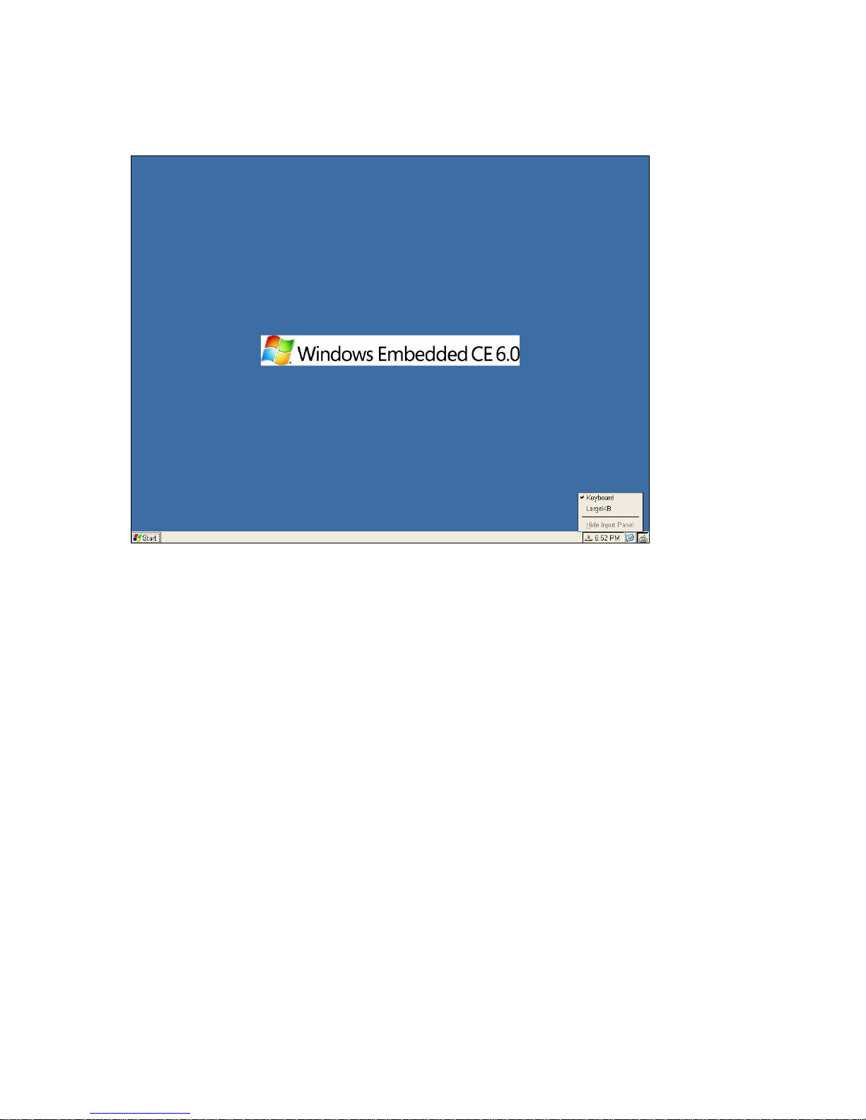
Software keyboard input panel
User can right click the mouse on Task Bar to select the Software keyboard to show input panel dialog.
User can select normal/Large keyboard to use, or even hide it by using this dialog.
____________________________
ADDS 5300 Win CE
42
Page 48
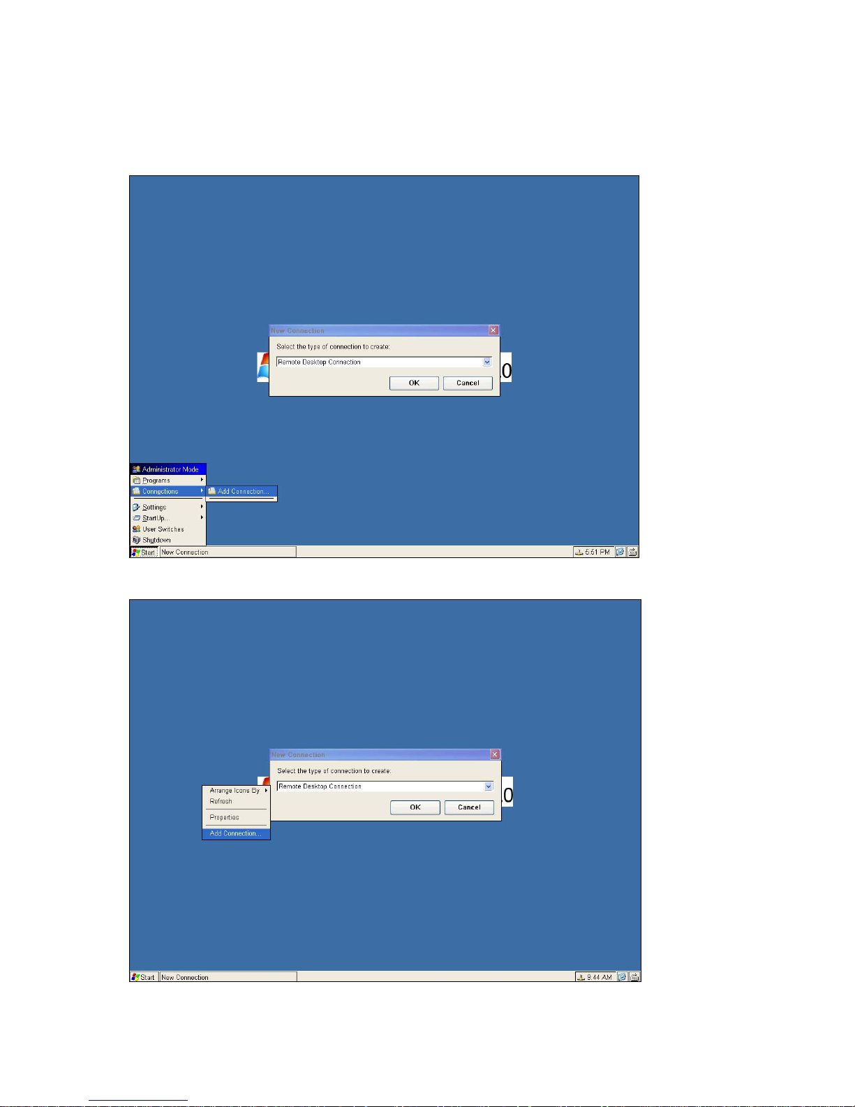
4 Connections Management
Connections are designed to help you manage your terminal's protocol connections. The dialog box displays after the user
select the item Add Connection on Start Menu, or left-click on desktop and select the item Add Connection.
Open the dialog by Start Menu
Open the dialog by desktop left-click
____________________________
ADDS 5300 Win CE
43
Page 49
4.1 Creating New Connections
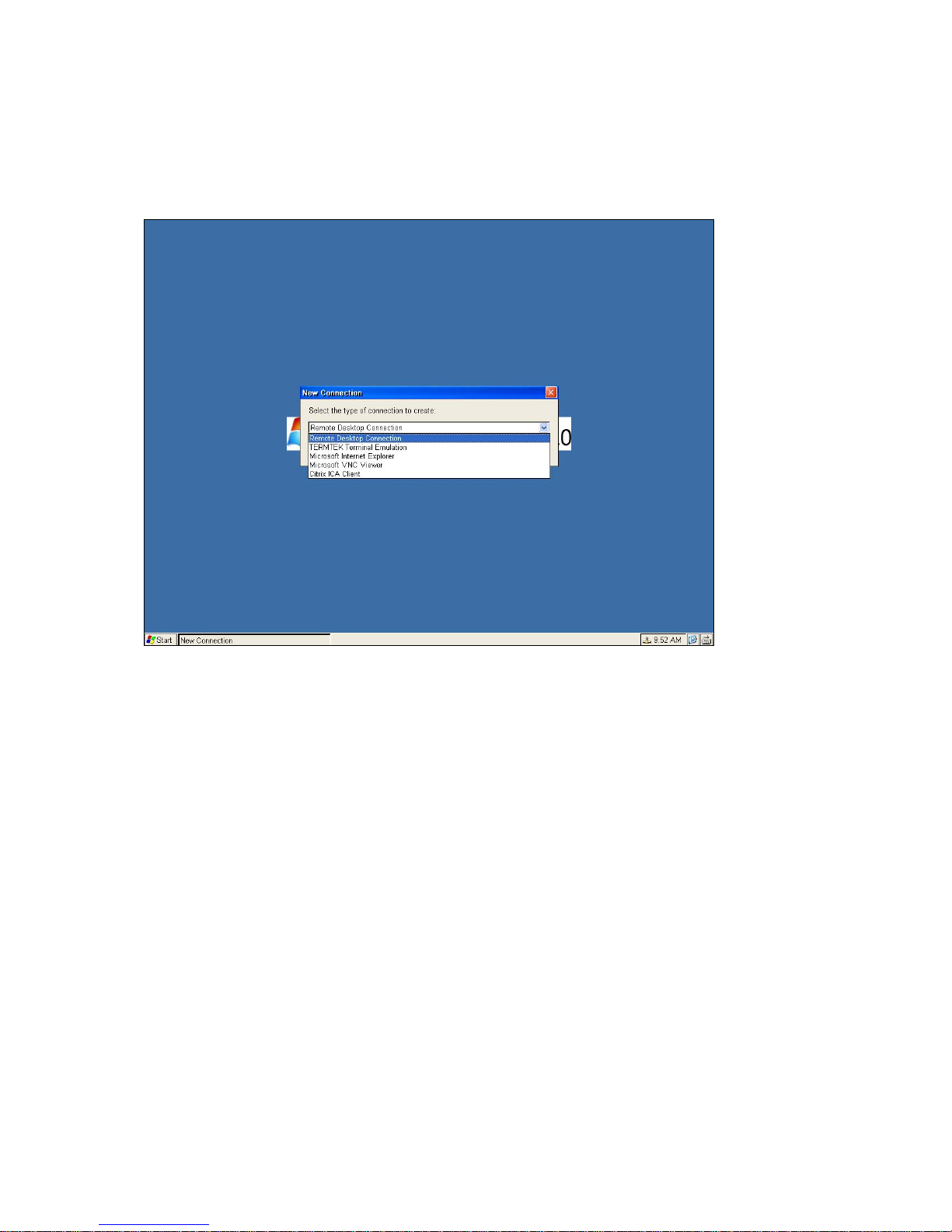
The New Connection dialog box is used to create new network connections. This dialog box is invoked by:
Clicking on the Configure tab in the Terminal Connection Manager dialog box. Clicking on Add command button on the
Configure properties sheet. The following figure shows the New Connection dialog box.
New Connection Dialog Box
4.1.1 Choosing a Connection Protocol
Use the scroll list shown in the dialog box above to select the type of connection protocol you want. When you choose from
the list above, you are deciding which connection protocol you want to use to connect to a server. Five selections are
available:
Microsoft Remote Desktop Client
RDP (Remote Desktop Protocol) protocol, through which connects to a WBT (Windows-Based Terminal) server. Refer
to chapter 4.4 for RDP Connections.
Citrix ICA Cli ent
ICA (Independent Computing Architecture) protocol, through which connects to an ICA (Winframe/M etaf r ame ) server.
Refer to chapter 4.5 for ICA Connections.
Microsoft Internet Explorer
Connects to the Internet directly via embedded Internet Explorer. This function doesn’t appear in all WBT s . Pleas e
make sure your WBT contains embedded IE and has 64MB RAM at least. Refer to chapter 4.7 for the Internet
applications.
Terminal Emulation/ IBM Terminal Emulation
Connects to multiple terminal or IBM-related emulation applications.
VNC viewer
Connects to the device which VNC server is enabled.
____________________________
ADDS 5300 Win CE
44
Page 50
4.2 RDP Connections
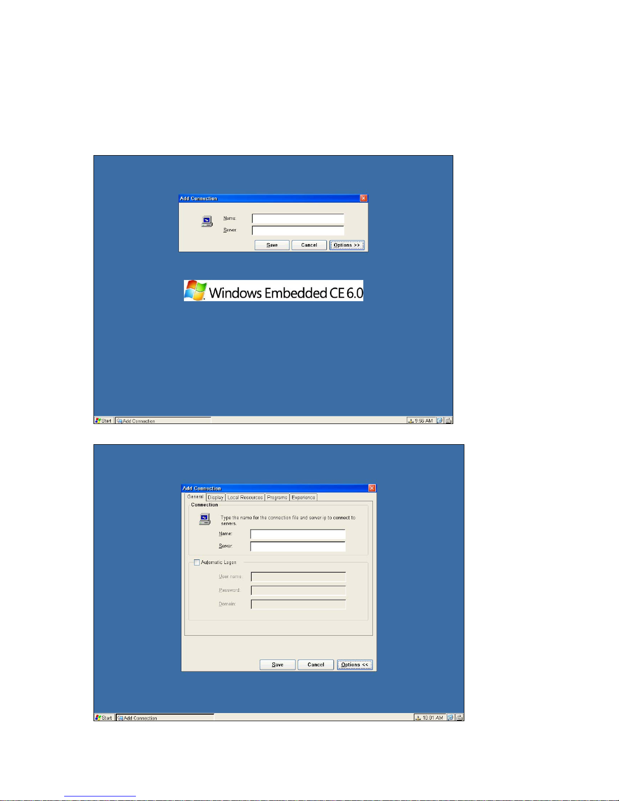
To create a new RDP connection, use the Add Connection dialog.
Enter the Name for the new connection and type IP Address or DNS Name to connect to the server.
Click on the Save command button to finished, the new connection will be added to the Connections list in Start Menu.
Click on the “X” icon on the top right of this dialog box or Cancel to quit the setting at any time.
Add new RDP connection dialog
Click on the Options command button to go to the Options dialog box.
____________________________
ADDS 5300 Win CE
45
Page 51
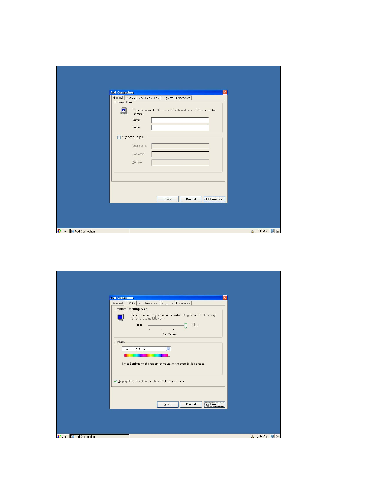
4.2.1 General Tab
Change the Name and IP Address or DNS Name for the connection.
If you want to logon automatically, enable Automatic Logon and type the Username, Password and Domain.
4.2.2 Display Tab
Change the Colors and Remote Desktop Size for RDP connection.
If default the connection bar is enable. The connection bar will be showed on the Windows desktop. If it is disable. The
connection bar will be hided.
____________________________
ADDS 5300 Win CE
46
Page 52
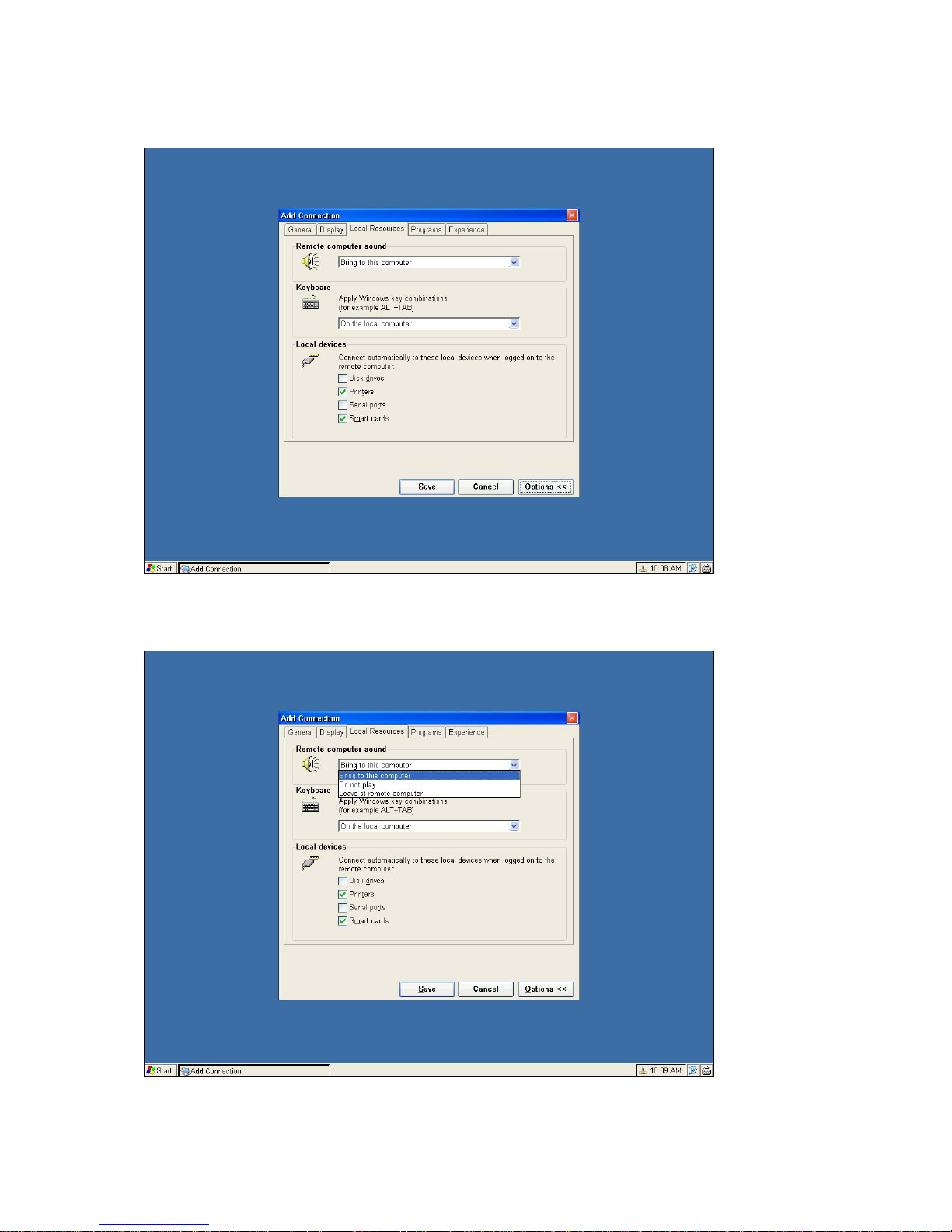
4.2.3 Local Resource Tab
Functions shown in local device.
Remote Computer sound
Choosing “Bring to this computer”.
Could bring the sounds from the server to the client device.
____________________________
ADDS 5300 Win CE
47
Page 53
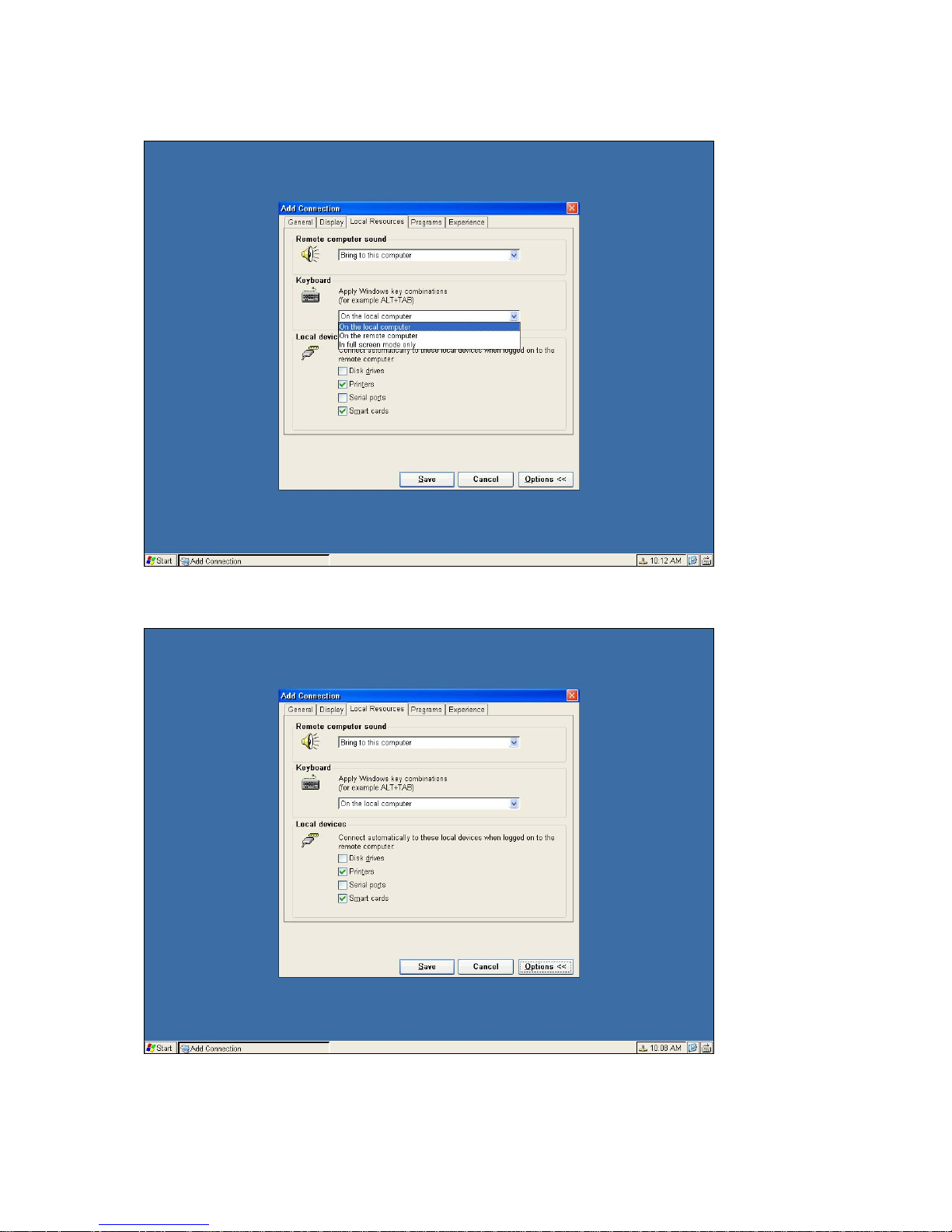
Keyboard
Apply windows key combinations-user can chose the system hot key actives on client or server
Local devices
User can enable these options before connecting to server, if the devices are installed ready,
User can use them on server.
____________________________
ADDS 5300 Win CE
48
Page 54
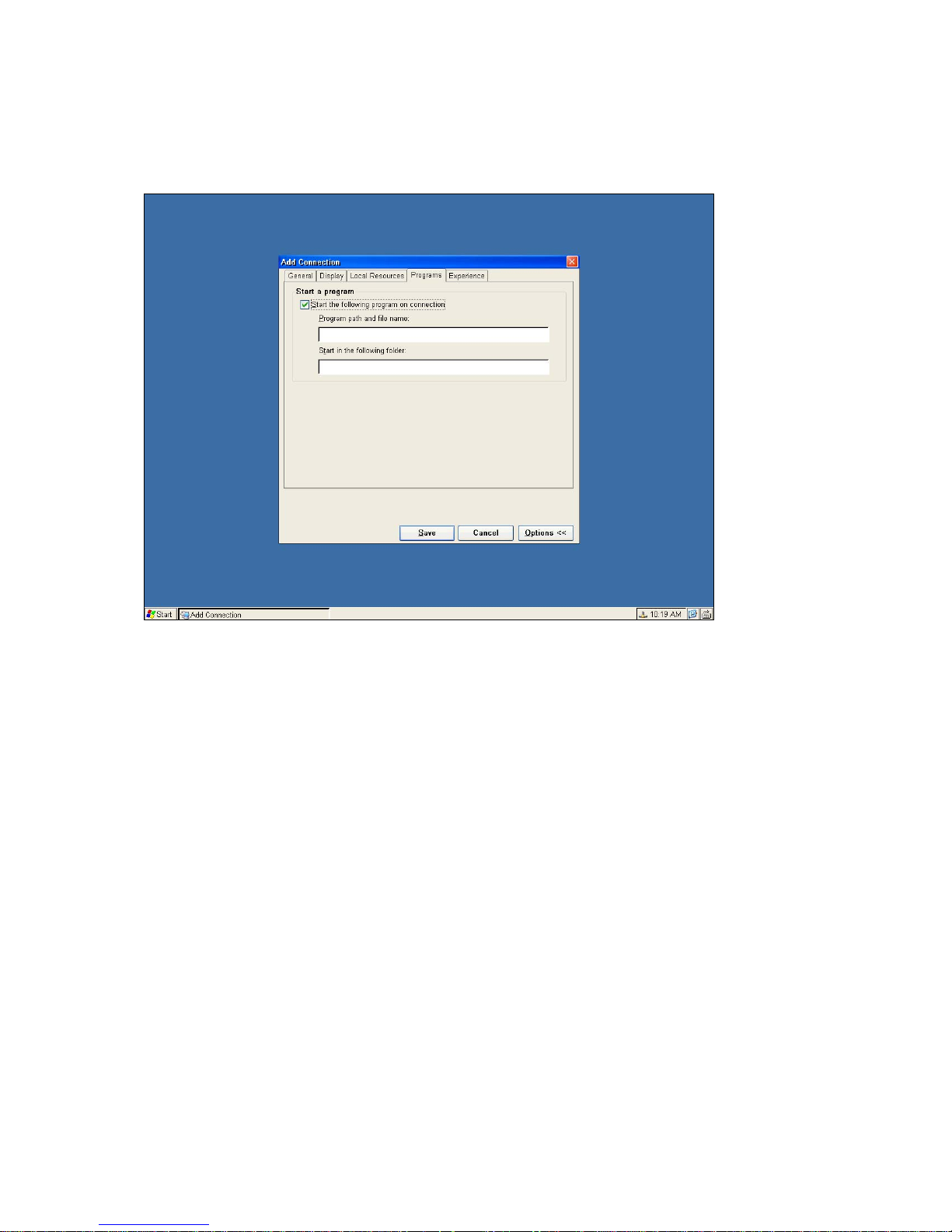
4.2.4 Programs Tab
Click on Desktop if you want the Windows NT desktop displayed by default while connecting. Or click on Application file
name and type its name when you want to start this application while connecting. You can also specify a working directory
when you specify an application.
4.2.5 Experience Tab
The Experience properties sheet lets you configure the connection speed.
____________________________
ADDS 5300 Win CE
49
Page 55
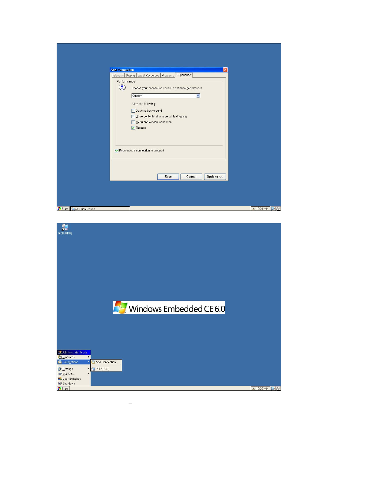
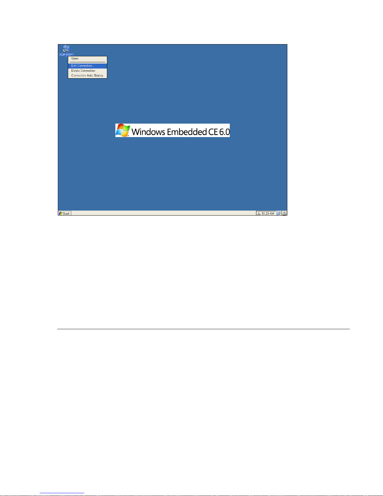
After finish the setup then you can see the new connection shortcut showed on desktop and Start Menu.
Left-click the shortcut and click E
Connection Name as shown on page 46, then follow the setup procedures again after selecting the connection.
____________________________
ADDS 5300 Win CE
dit Connection if you want to edit the RDP. The screen will go back to Select the
50
Page 56
4.3 ICA Connections
Use this application to create a Citrix ICA connection. Choose the Network Connection or Dial-In Connection for the remote
application.
4.3.1 Creating a New ICA Connection Entry
You can configure and run two types of ICA sessions: Citrix server connections and published applications.
Citrix server connections allow you to remotely control a session on a Citrix server from your WBT. Citrix server
connections let you access the desktop of a specific Citrix server; you can run any applications available on the
desktop, in any order.
Published applications are specific applications set up by an administrator for remote users to run. When connected,
you are presented with the application itself.
This procedure describes the simplest way to create a connection entry. When you follow these steps, you set the
Note
essential items you need to connect to a Citrix server from your WBT. See “Changing a Connection Entry” for more
information about how to change the other properties for a connection entry.
4.3.1.1 To create a new connection entry
In the New Connection dialog box, click the list box and select Citrix ICA Client. Click OK.
The Specify Connection Type dialog box appears:
Make sure your WBT is connected to the network through the on-board RJ-45 connector or by a serial PPP connection to a
Windows 95 or Windows NT RAS server. Click Next to continue. Skip to section 4.5.1.2.
____________________________
ADDS 5300 Win CE
51
Page 57
Note
The ICA Windows-based Terminal does not support modem callback. When using modem callback, the server hangs
up on dial-in connections at logon and then dials a specified number to reconnect to the user attempting to log on. Because
Windows-based Terminal contains no mechanism to answer the return call, the ICA Windows-based Terminal does not
support modem callback for dial-in connections.
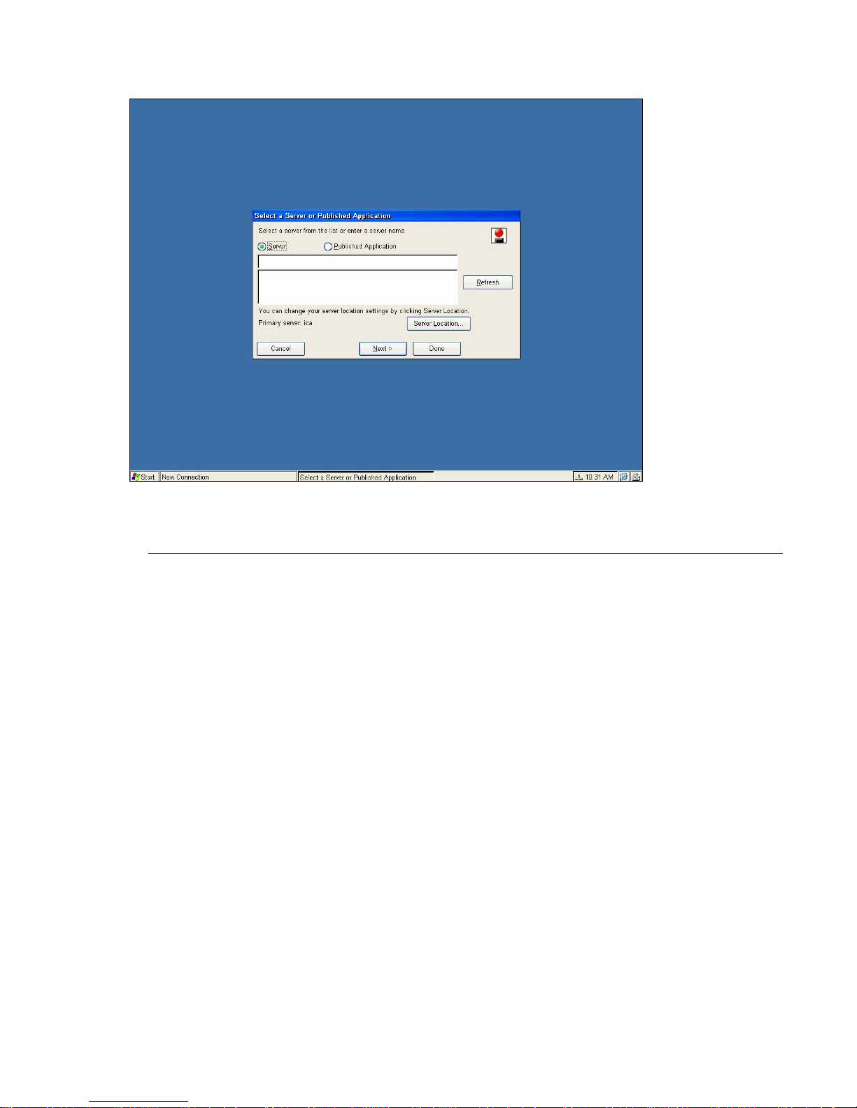
4.3.1.2 The Select a Server or Published Application dialog appears:
____________________________
ADDS 5300 Win CE
52
Page 58
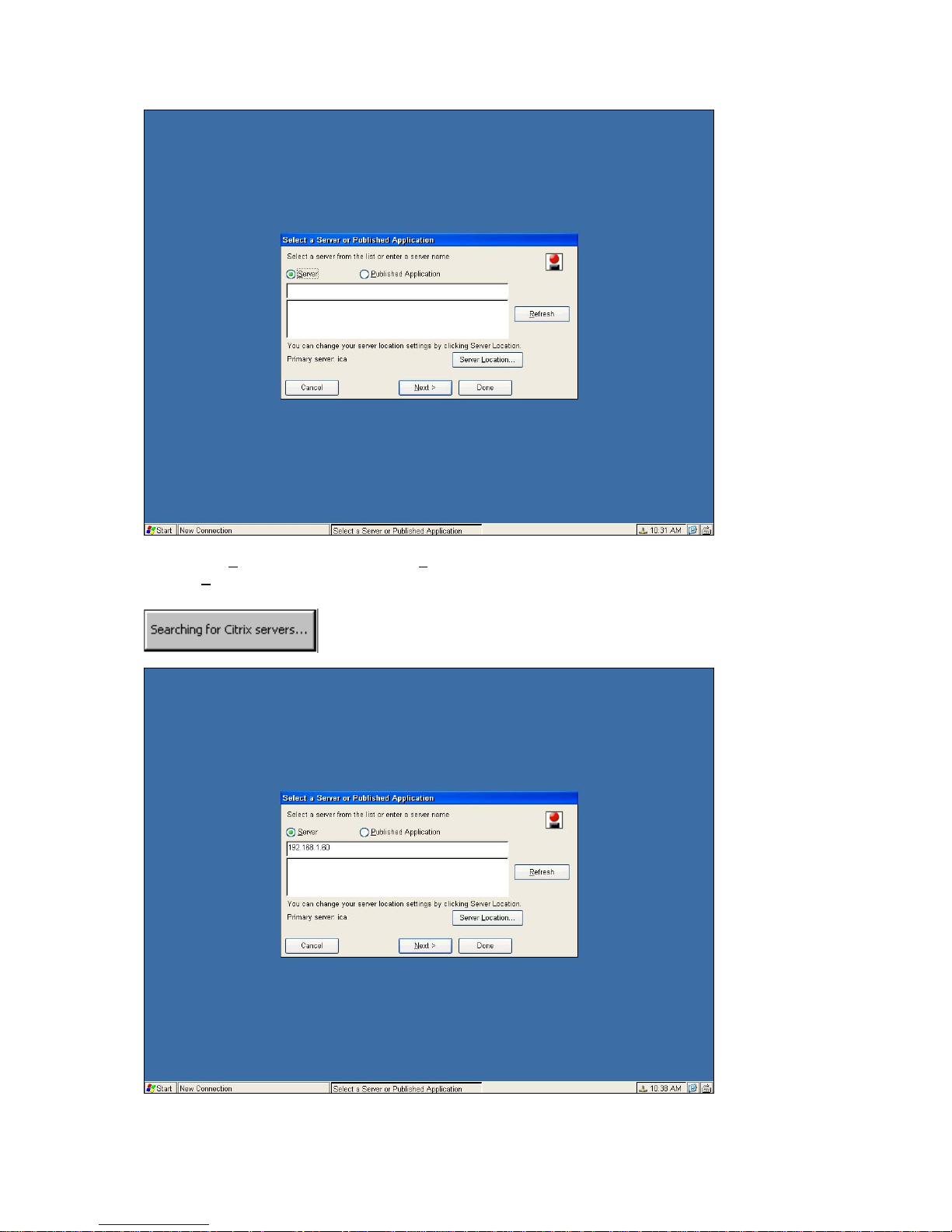
4.3.1.3 Click Server to connect to a server or Published Application to connect to a published application. Click
“R
efresh” and then WBT will search for the available Citrix servers on the network. A message will display as
below:
Then the available Citrix server names will be displayed:
Select a Citrix server you would like to connect to:
____________________________
ADDS 5300 Win CE
53
Page 59
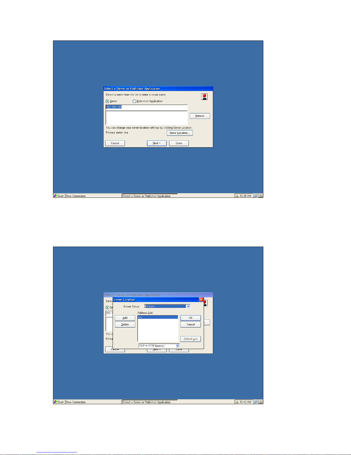
If your WBT is not on the same network as the Citrix server you would like to connect to, the server name will not appear in
the list (this would occur if you are on the other side of a router, across the Internet, or using RAS to connect to a remote
network containing Citrix servers). In this case, click Server Location and go to section 4.5.1.5. Otherwise, scroll through the
list and select the Citrix server or published application or type the name of the Citrix server or published application in the
edit field. Click Next to continue, and go to section 4.5.1.5.
4.3.1.4 The Server Location dialog box appears:
____________________________
ADDS 5300 Win CE
54
Page 60
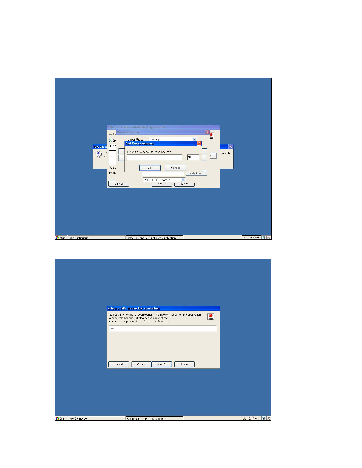
Remote Application Manager uses the information entered in the Server Location screen to help locate available Citrix
servers and published applications.
The default server location protocol is TCP Browser and the default value entered in the Address field is Auto-Locate.
Click Add and enter the IP address or DNS name of any Citrix server on the remote network. Click OK, and then click Next
to section 4.5.1.5. The following figures show the sequence of settings.
4.3.1.5 The Select a Title for the ICA Connection page appears:
____________________________
ADDS 5300 Win CE
55
Page 61
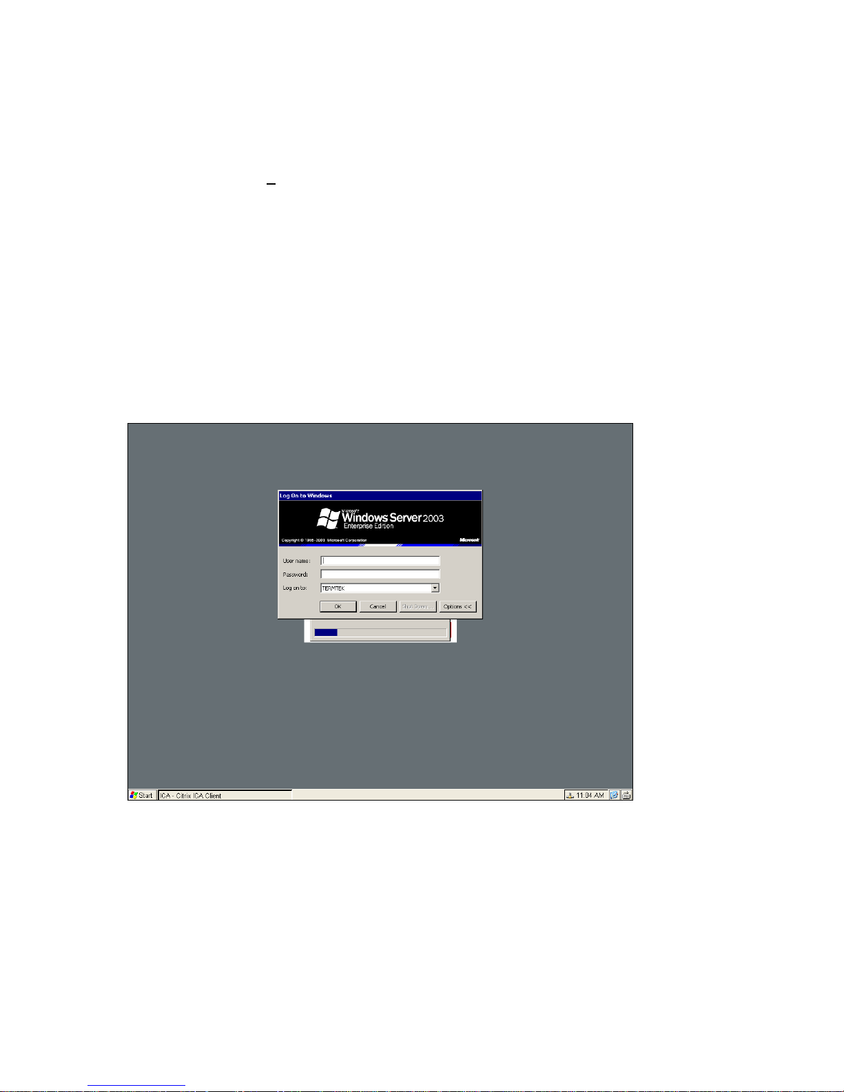
Enter a name for the connection entry. The name you choose is the name of the entry in the Current Client Connections
list and appears in the title bar of the ICA session window.
4.3.1.6 Click “Done” to save the entry or “Cancel” to exit the new connection entry dialog box without saving the entry. You
also can click on “N
4.5.3.2 to 4.5.3.6. Once you have created a connection entry, the name appears in the list of connections in
Connection Manager.
ext” to continue configuring other detail settings; the details will be described in section from
4.3.2 Connecting to a Citrix Server
4.3.2.1 To start a previously defined connection
a. In the C onnection Manager dialog box, click the Connections tab.
b. Select the desired connection name and click Connect.
If you specified a valid user name and password in the connection entry, you are logged in as that user.
If no user name and password are present in the entry or the information is incorrect, the server logon dialog box appears.
Enter a valid user name and password for the Citrix server and click “OK” to log on
.
____________________________
ADDS 5300 Win CE
56
Page 62
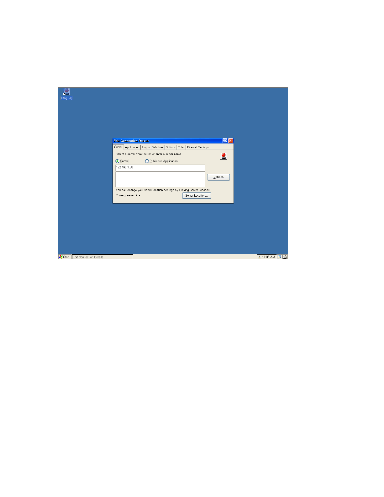
4.3.3 Changing a Connection Entry
This section describes how to change the properties of an existing connection entry.
4.3.3.1 To change the properties of a connection entry
Left-click the name of the connection entry that you want to change.
Click Edit Connection to display the Edit Connection Details dialog box.
Make the desired changes.
Click OK to save your changes.
The Edit Conne ction Details dialog box contains the following tabs:
a. The Server tab (network connection entries only), where you can set the server or published application name to which
to connect. There is also a button to display the Server Location dialog box where you can set Business Recovery
options, please refer to section 4.5.1.5 for more information.
b. The Dial-in tab (dial-in connection ent ries only), where you can set the area code, country code, and telephone number
to dial. You can use the settings on this page in the same way as when you first set up the connection entry, see
“Creating a New Connection Entry” for more information.
c. The Application tab, where you can specify an application to run after connecting to a Citrix server, see section 4.5.3.2
“Specifying an Application to Run after Connecting to a Citrix Server” for more information.
The
d.
e. The Window tab, where you can set the number of colors used for the ICA Client window, see section 4.5.3.4
f.
g. The Title tab, where you can change the name of the connection, the name appears in the list in the Connection
The Firewall Settings tab, where you can configure the client to use a SOCKS proxy and alternate address
re-mapping, see section 4.5.3.7 “Configuring Firewall Settings” for more information.
Logon tab, where you can set the user name, password, and domain to log in to the Citrix server automatically, see
section 4.5.3.3 “Specifying Logon Information” for more information.
“Changing the Window Properties” for more information.
The Options
support, see section 4.5.3.5 “Setting Connection Entry Options” for more information.
Manager dialog box. See section 4.5.3.6 “
, where you can control
Tab
the connection between the Citrix server and your WBT and configure sound
____________________________
ADDS 5300 Win CE
57
Page 63
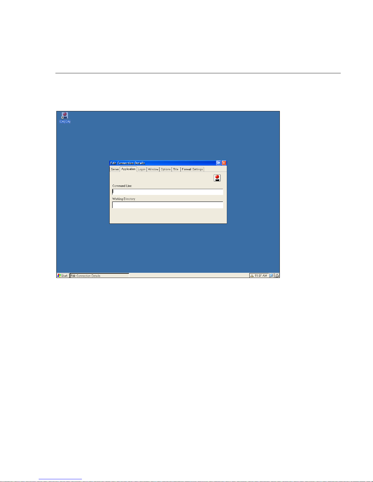
4.3.3.2 Specifying an Application to Run after Connecting to a Citrix Server
Use the Application tab to specify an application to run after connecting to a Citrix server. If you specify an application, you
do not see the Windows desktop when you connect and the connection is closed when you exit the application.
Note
This tab does not apply to connection entries for published applications. Any value entered is ignored.
a. In the Connection Manager dialog box, click Configure.
b. Select the connection entry that you want to change and click Edit.
c. Click the Application tab.
d.
In the Command Line box, specify the path and file name of the application to be run after connecting to the Citrix
server. For example, to launch Notepad automatically after connecting to the Citrix server, type:
e. In the Working Directory box, specify the working directory to be used with the application. If you use Notepad to work
on documents in the C:\My Documents directory, type C:\My Documents.
f. Click OK to save your changes.
When you log on to the Citrix server, Notepad begins. In Notepad, if you select Open from the File menu, the C:\My
Documents directory is displayed.
C:\Wtsrv\Notepad.exe
____________________________
ADDS 5300 Win CE
58
Page 64
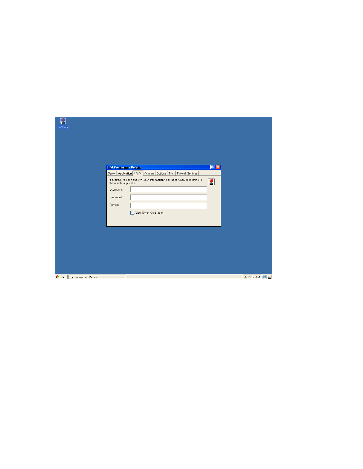
4.3.3.3 Specifying Logon Information
You can include the settings needed to log on to the Citrix server as part of the connection entry. This saves time when
connecting to the server but is less secure.
a. In the Connection Manager dialog box, click Configure.
b. Select the connection entry that you want to change and click Edit.
c. Click the Logon tab.
d. Type a valid user name, domain, and password. If you leave these boxes blank, you are prompted for your user name,
domain, and password each time you connect to the Citrix server or published application.
e. Click OK to save your changes.
____________________________
ADDS 5300 Win CE
59
Page 65
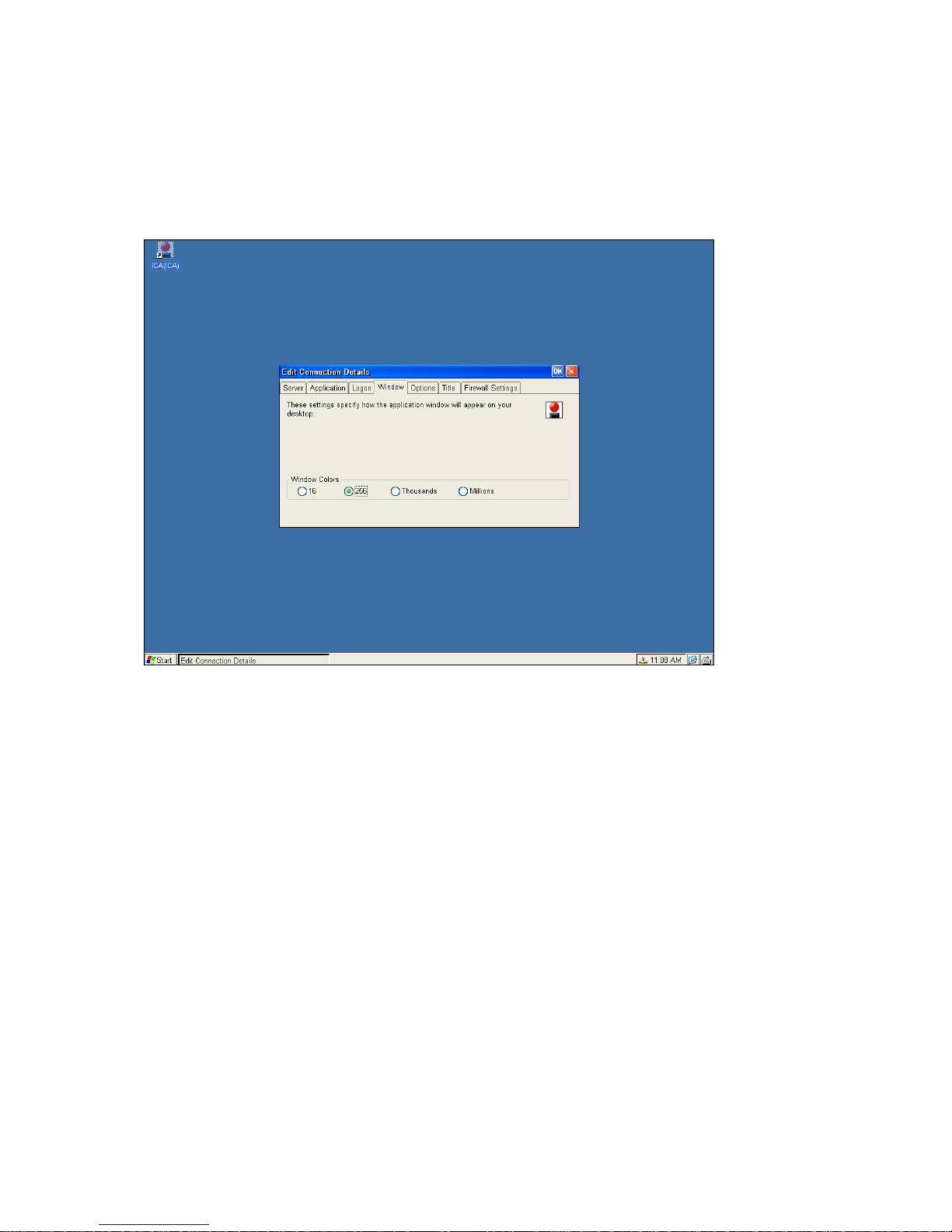
4.3.3.4 Changing the Window Properties
Use the Window tab to change the number of colors to use for ICA connections made using the connection entry.
a. In the C onnection Manager dialog box, click Configure.
b. Select the connection entry that you want to change and click Edit.
c. Click the Window tab.
d. In the Window Colors box, set the number of window colors to 16, 256, Thousands or Millions.
e. Click OK to save your changes.
____________________________
ADDS 5300 Win CE
60
Page 66
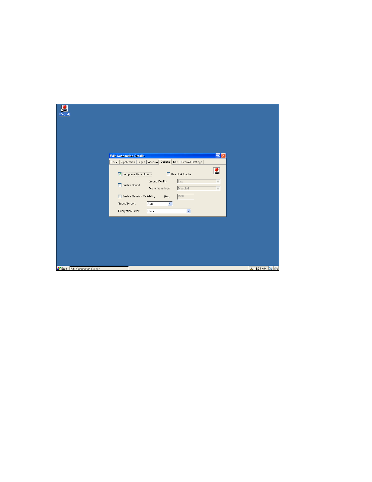
4.3.3.5 Setting Connection Entry Options
Use the Options tab to set options specific to the connection entry, such as data compression and sound support.
a. In the C onnection Manager dialog box, click Configure.
b. Select the connection entry that you want to change and click Edit.
c. Click the Options tab.
d. Click Compress Data Stream to reduce the amount of data transferred between the ICA Client and the Citrix server. If
your connection is bandwidth-limited, enabling compression can increase performance. If your client device is on a
high-speed LAN, you may not need compression. If you have sufficient bandwidth, leave compression off to conserve
processing power on the Citrix server.
e. The Cache feature is not supported in this ICA client version.
f. Click Enable Sound to enable sound support. From the pull-down list, select one of the following quality levels.
High. This value provides the greatest audio quality but should be used only when bandwidth consumption is not a
concern.
Medium. Using this value results in less bandwidth consumption than when using High. Compression of sound data
provides greater bandwidth efficiency but reduces sound quality somewhat. This value is recommended for most LAN-based
connections.
Low. This value offers the most efficient use of bandwidth but also decreases sound quality severely. This value is
recommended for low-bandwidth connections, including most modem connections.
g. Click OK to save your changes.
____________________________
ADDS 5300 Win CE
61
Page 67
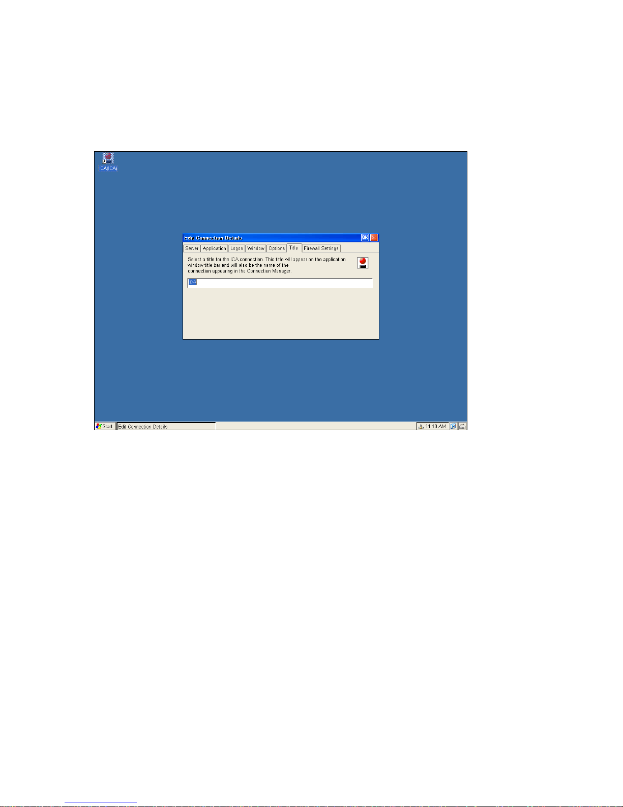
4.3.3.6 Changing the Title of the Connection Entry
By click on the Title tab you can change the title of this selected connection entry.
Click OK to save your changes.
____________________________
ADDS 5300 Win CE
62
Page 68
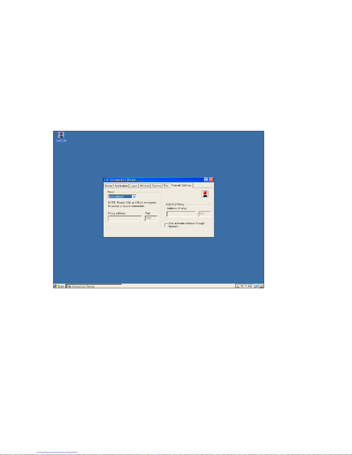
4.3.3.7 Configuring Firewall Settings
If you are using a SOCKS proxy server to limit access to your Citrix servers, you must configure the ICA Client to connect to
Citrix servers through a SOCKS proxy server. You can configure a default SOCKS proxy for all connections or use only a
SOCKS proxy with a specific connection file. To do the former one please refer to the section
To configure a SOCKS proxy server for a specific co nnection entry
a. In the C onnection Manager dialog box, click Configure.
b. Select the connection entry that you want to change and click Edit.
c. Click the Firewall Settings tab.
d. Click Connect via SOCKS proxy.
e. In the Address of proxy to use box, enter the SOCKS proxy server’s IP address.
f. In the Port box, enter the proxy server's port number (if different th an 1080).
g. Click OK to save your changes.
____________________________
ADDS 5300 Win CE
63
Page 69
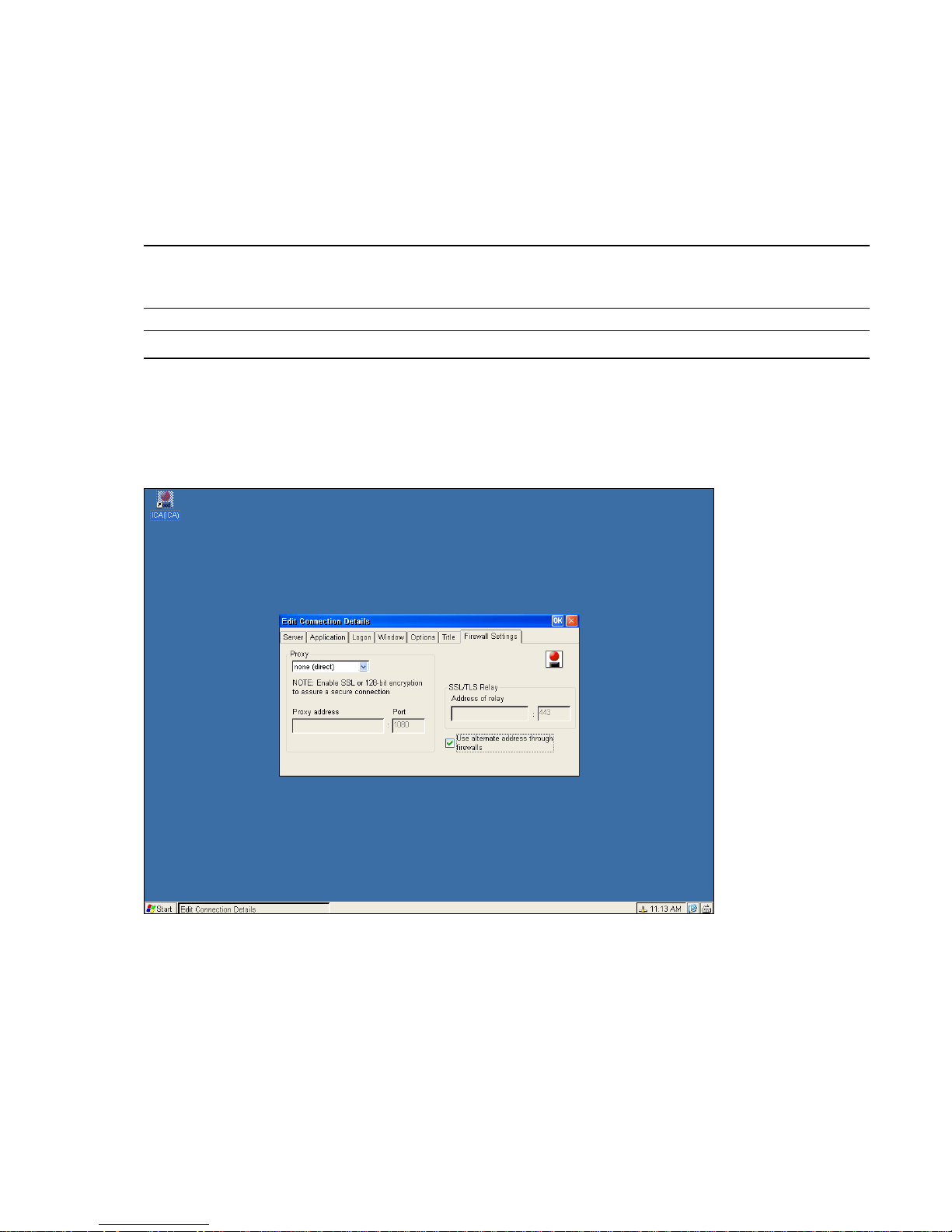
Configuring Alternate Address Translation
If the ICA Client is outside a firewall that uses address re-mapping, you must configure the ICA Client to use the alternate
address returned by the master ICA Browser. This is necessary even if you are not using a SOCKS proxy server.
You must also use the ALTADDR utility to manually set the alternate address for each Citrix server, See the
Note
Command Reference appendix of either the MetaFrame Administrator’s Guide or the W
information.
If you set alternate address translation for all connection entries, it cannot be disabled for specific c onnect i on entrie s.
Note
INFRAME System Guide for more
To use alternate address translation for a specific connection entry
In the Connection Manager dialog box, click Configure.
Select the connection entry that you want to change and click Edit.
Click the Firewall Setting s tab.
Click Use alternate address for firewall conn ecti on.
Click OK to save your changes.
____________________________
ADDS 5300 Win CE
64
Page 70
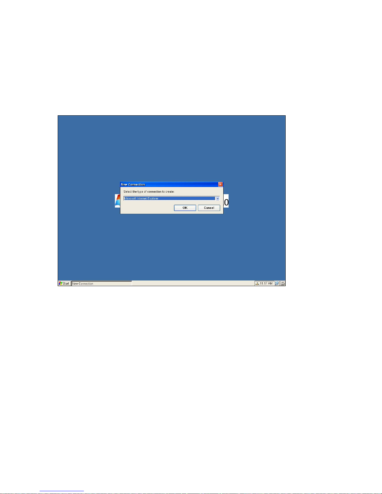
4.4 Microsoft Internet Explorer Connection
This is an optional function for your WBT; check your vender for this support before your purchase. This local browser
connection will require more RAM utilization and powerful CPU to have better performance. This WBT is equipped with a
CPU of outstanding speed to offer you a local browser session you never experience before.
4.4.1 To Make a New Microsoft Internet Explorer Connection
To make a new connection follow the below steps: choose Microsoft Internet Explorer. Then click on OK to continue.
The following figure shall now appear. Type a name and your desired Start Page for this connection.
____________________________
ADDS 5300 Win CE
65
Page 71
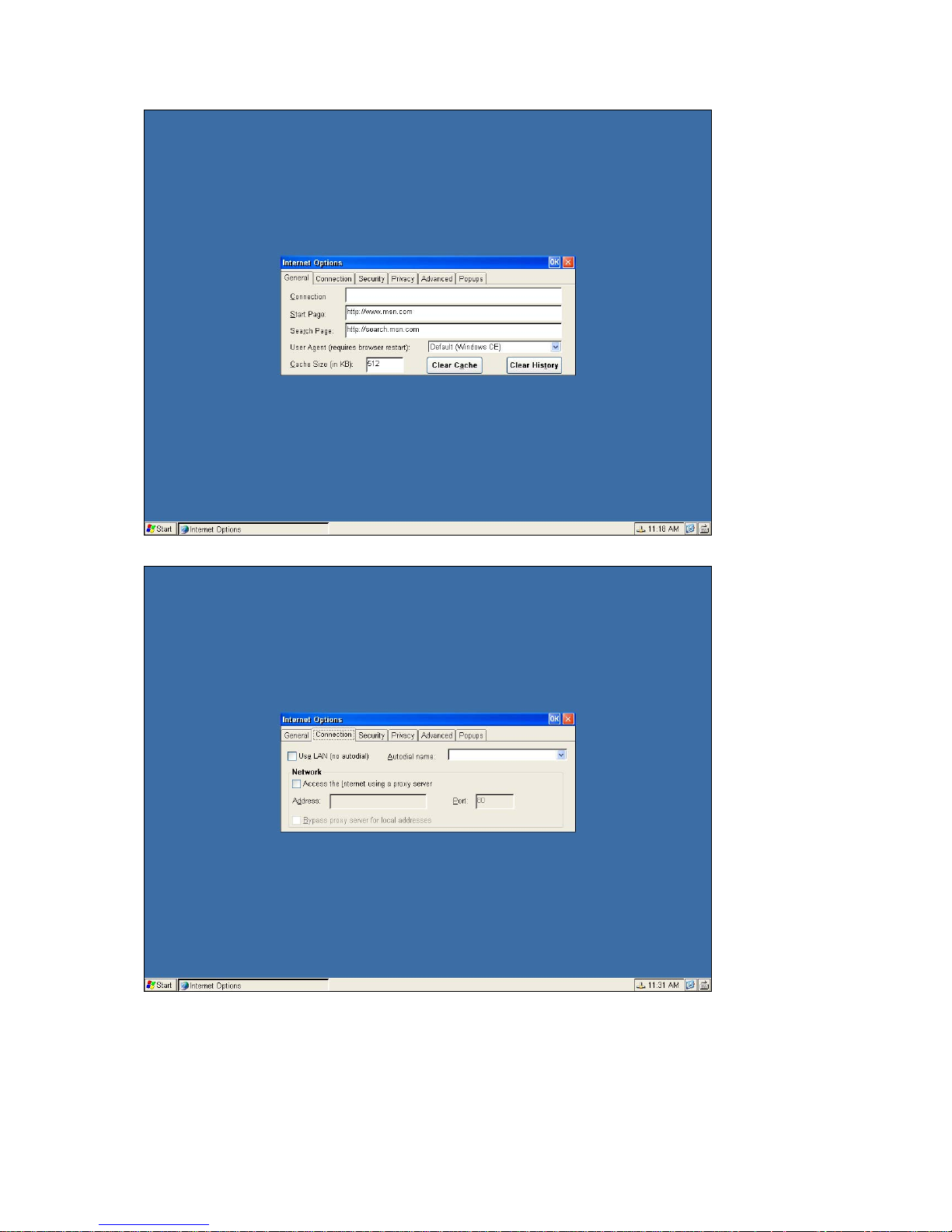
You could choose to connect by LAN on “dial up”.
a. If you have a proxy server, you could enable it when access to the Internet.
b. Or you could by pass your proxy server when connecting to the local Internet.
____________________________
ADDS 5300 Win CE
66
Page 72
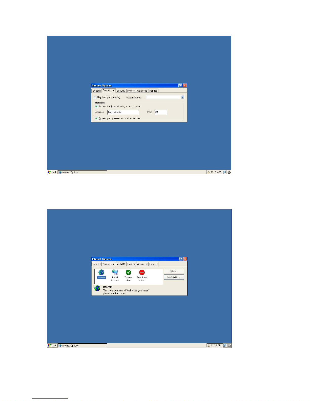
This column is the security settings for Internet.
____________________________
ADDS 5300 Win CE
67
Page 73
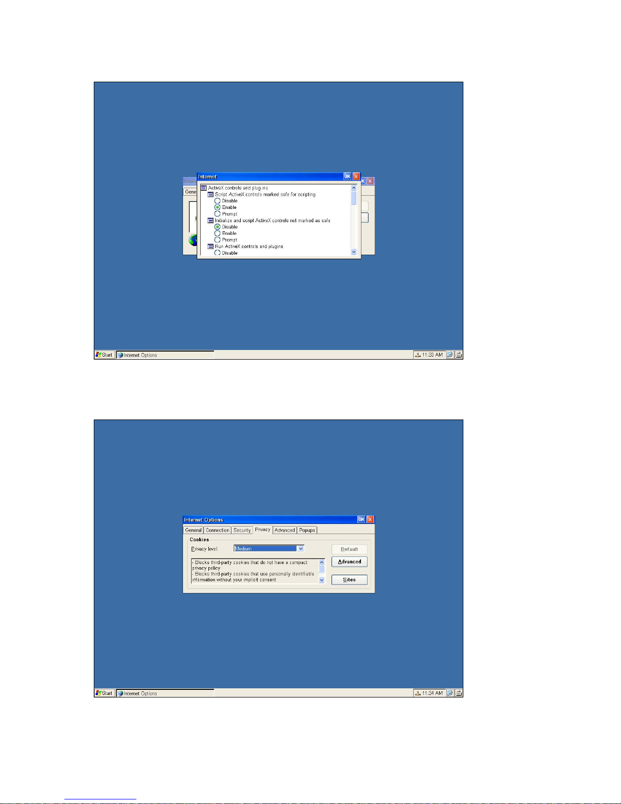
You can customize the security level in this dialog box.
The privacy Internet setting can be set up in this dialog box.
In this dialog box, you can setup the advanced Internet setting.
____________________________
ADDS 5300 Win CE
68
Page 74
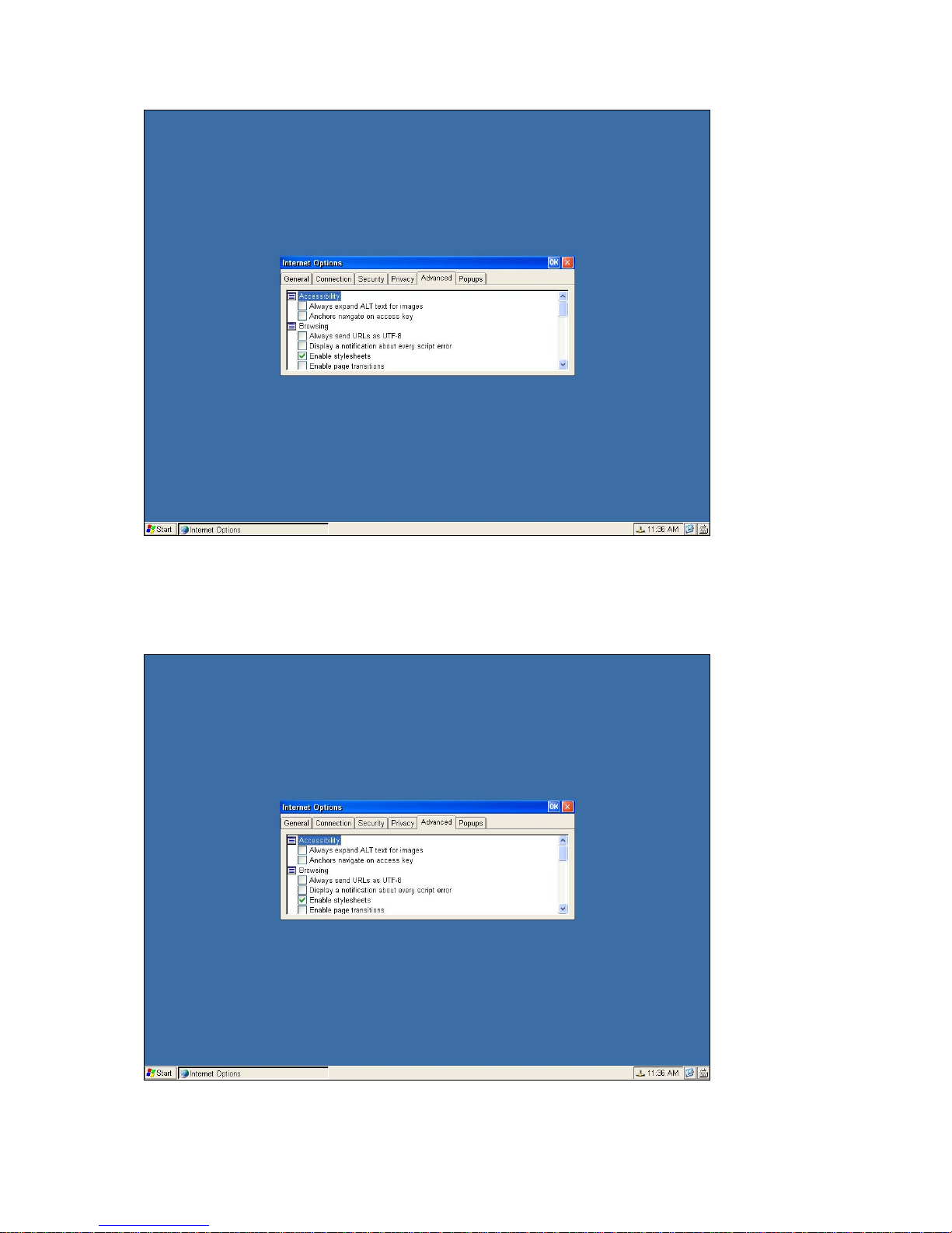
You can block the popup windows in the Popup dialog box. .
____________________________
ADDS 5300 Win CE
69
Page 75
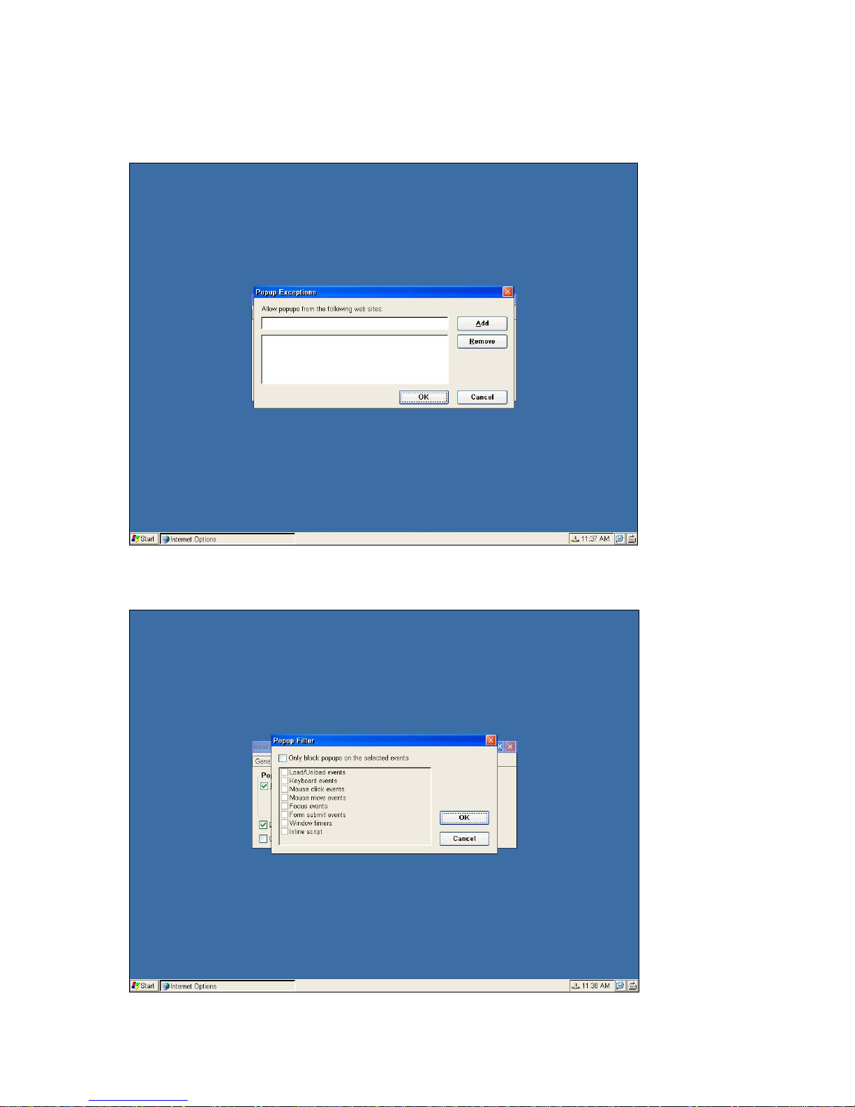
Set the web sites that you allow to popup.
You can also select the events you want to block their Popup
.
____________________________
ADDS 5300 Win CE
70
Page 76
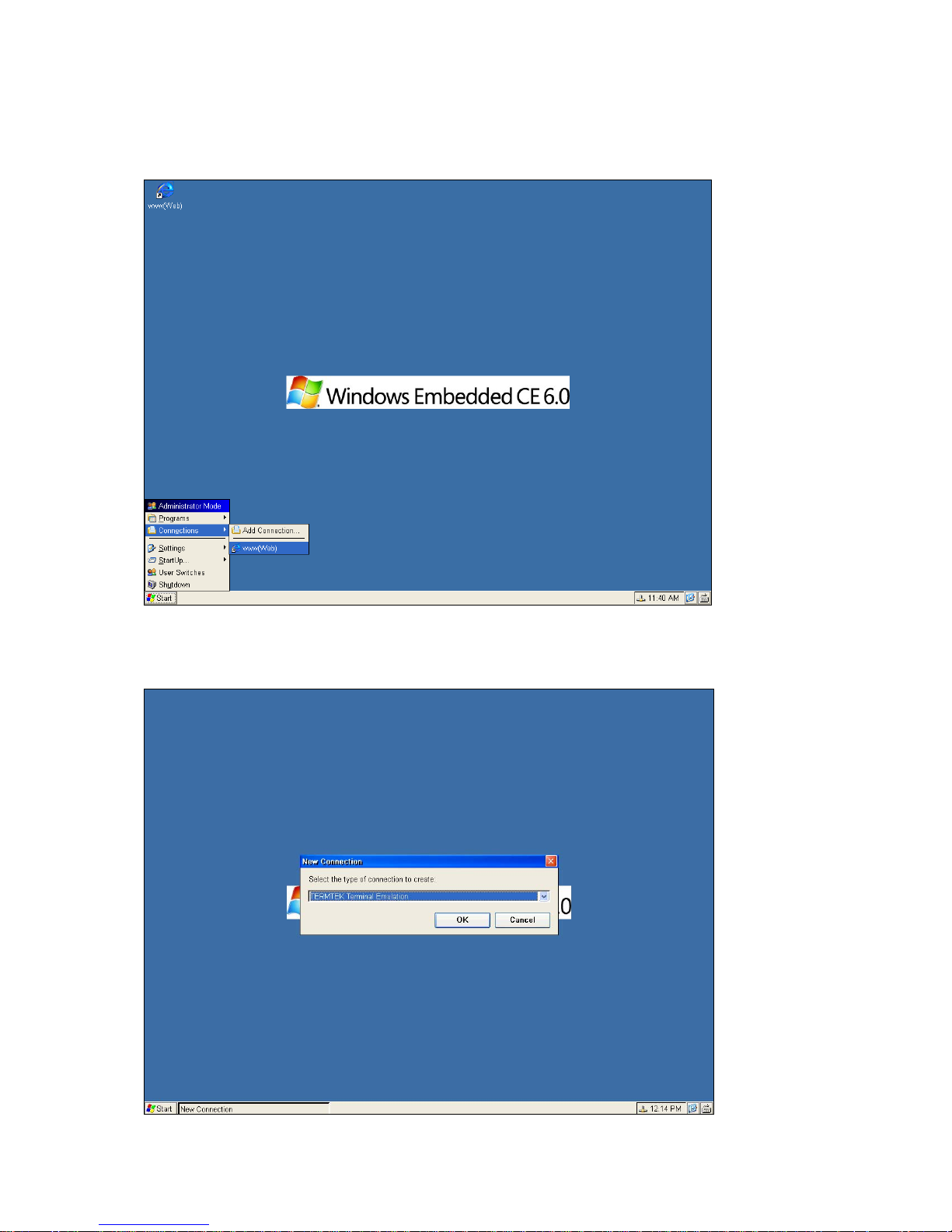
4.4.2 To Start a Microsoft Internet Explorer Connection
Double click this Web connection. If your network settings have been correctly set up then this is going to work.
4.5 TERMTEK Terminal Emulation
User can add a connection of ASCII ANSI Emulation or IBM Emulation by this application.
____________________________
ADDS 5300 Win CE
71
Page 77
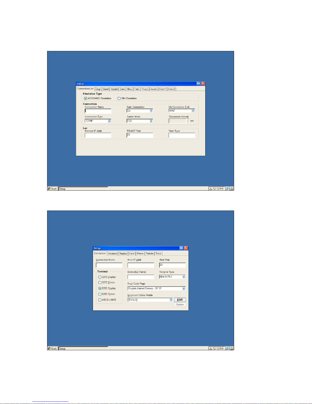
ASCII/ANSI Emulation settings Page
IBM Emulation settings Page
Finish the set up, the connection will be added on desktop and list.
____________________________
ADDS 5300 Win CE
72
Page 78
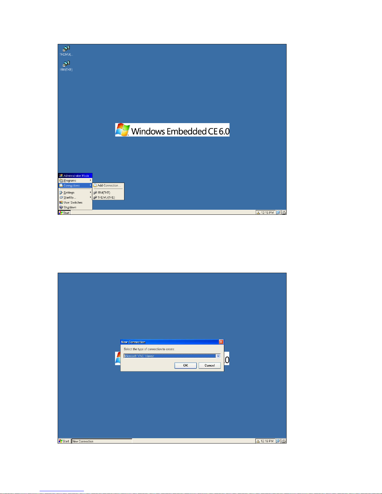
4.6 Microsoft VNC Viewer
Microsoft VNC Viewer provides user to add a connection of VNC, to connect to other server that enable the VNC service.
____________________________
ADDS 5300 Win CE
73
Page 79
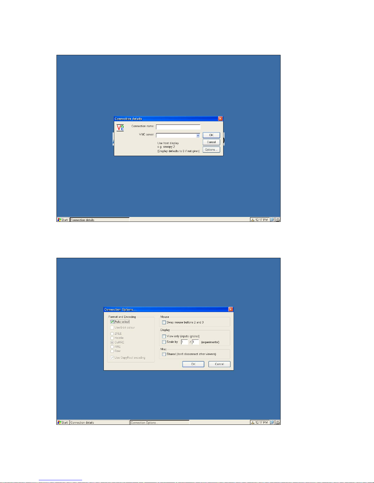
Add Connection
Set the options of connections
____________________________
ADDS 5300 Win CE
74
Page 80
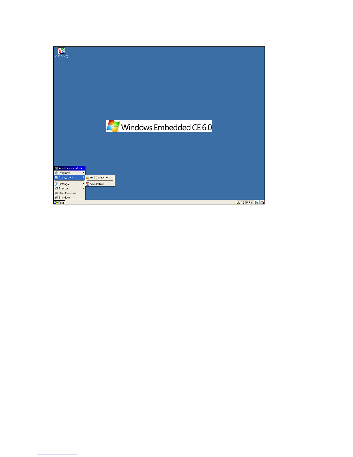
The connection will list on Start Menu and desktop, and user can click it to active it.
5 Advanced Function for Connections
This WBT provides some advanced function for all connections such as Multiple Auto Start-Up and Multiple Auto Reconnect.
5.1 Multiple Auto Start-Up
Left-click the connection, and then click on Auto Start, the following figure will appear:
____________________________
ADDS 5300 Win CE
75
Page 81
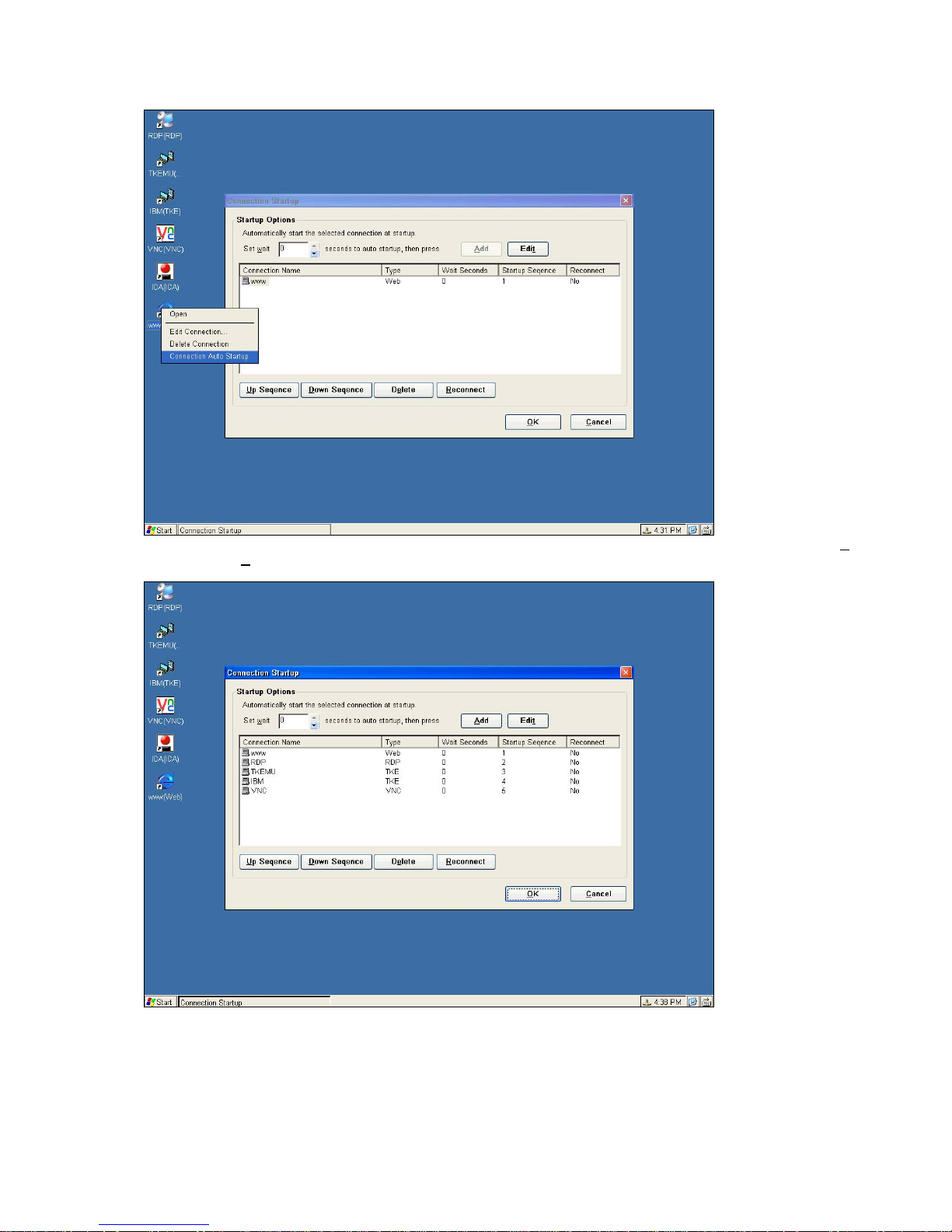
Click on “Add” to add this connection in the list of Startup list. You can repeat this action to have multiple Startups. Use “U
Sequence” and “D
make sure the user names and passwords for all selected connections have been set up properly.
own Sequence” to set the priority of starting all the connections. Before this function works successfully,
p
User also can manage it by select Auto Start Manager on Start Menu.
____________________________
ADDS 5300 Win CE
76
Page 82
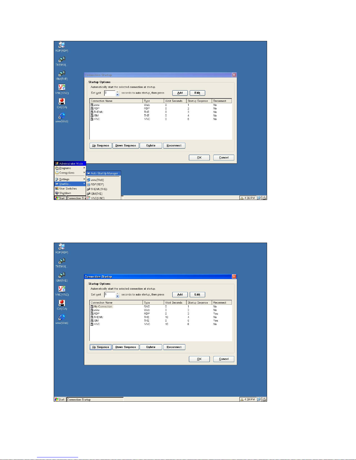
5.2 Multiple Auto Reconnect
In the same figure above you will also find an icon of “Reconnect”. This is to set this WBT to immediately and
automatically reconnect the same session that you have just logged off. This special function can be widely
Optimized when the WBT is placed in a public area.
6 Control Panel
____________________________
ADDS 5300 Win CE
77
Page 83
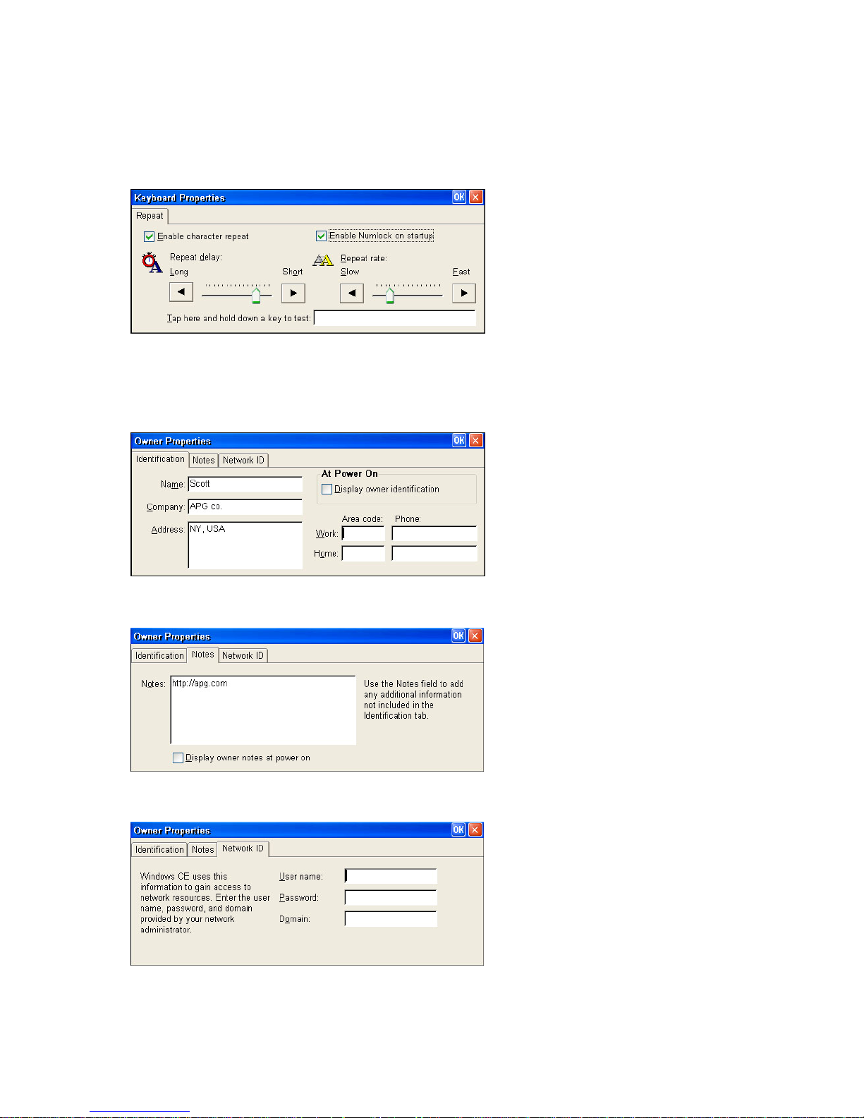
The Control Panel provides various tools and applications to config ure the WBT. One can easily configures the WBT with
the Control Panel. The Control Panel can be found in “Settings” of “Start Menu” or quickly opened by the Hotkey “ALT +
F2”.
6.1 Keyboard
The Keyboard properties sheet lets you configure your terminal's keyboard. Invoke this properties sheet by clicking on the
Keyboard icon. The following figure shows the properties sheet.
6.2 Owner
The Owner properties sheet lets users save personal information in the WBT.
6.2.1 Identification
To protect users rights, User could key in their identification data before entering connection manager. Enable ”display
owner identification” at power on, the information will show whenever the machine is on.
6.2.2 Notes
User could key in any sentences or words in the column. It will show up if you enable ”Display owner notes at power on”.
6.2.3 Network ID
Enter User name and Password when access to the Network.
6.3 System
____________________________
ADDS 5300 Win CE
78
Page 84
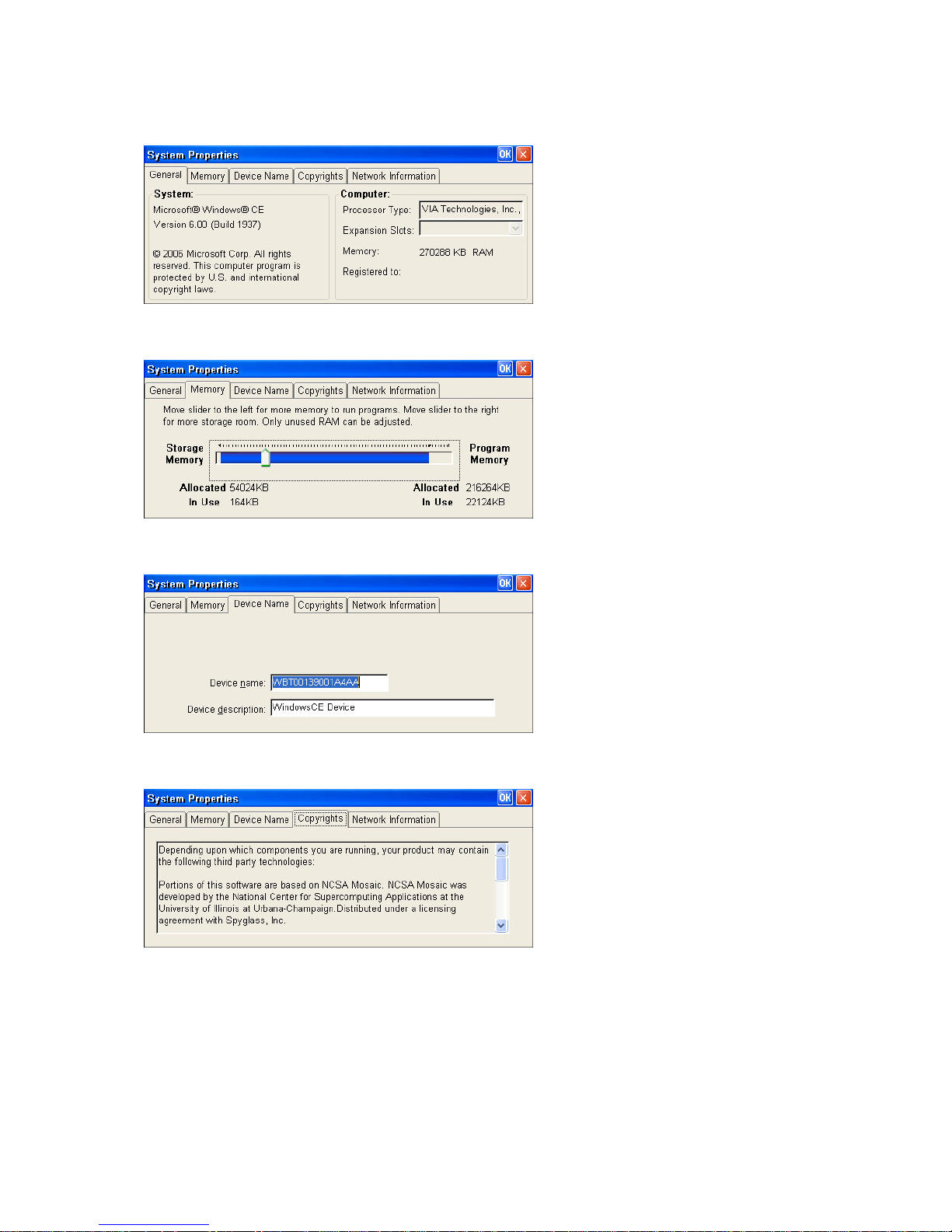
6.3.1 General
By clicking on the “General” icon, all the system information will be displayed.
6.3.2 Memory
By clicking on the “Memory” icon, you can adjust the memory as you want to run the programs.
6.3.3 Device Name
By clicking on the “Device Name” icon, you can identify your Windows CE device to other computers.
6.3.4 Copyrights
By clicking on the “Copyrights” icon, the agreement information will be displayed.
____________________________
ADDS 5300 Win CE
79
Page 85
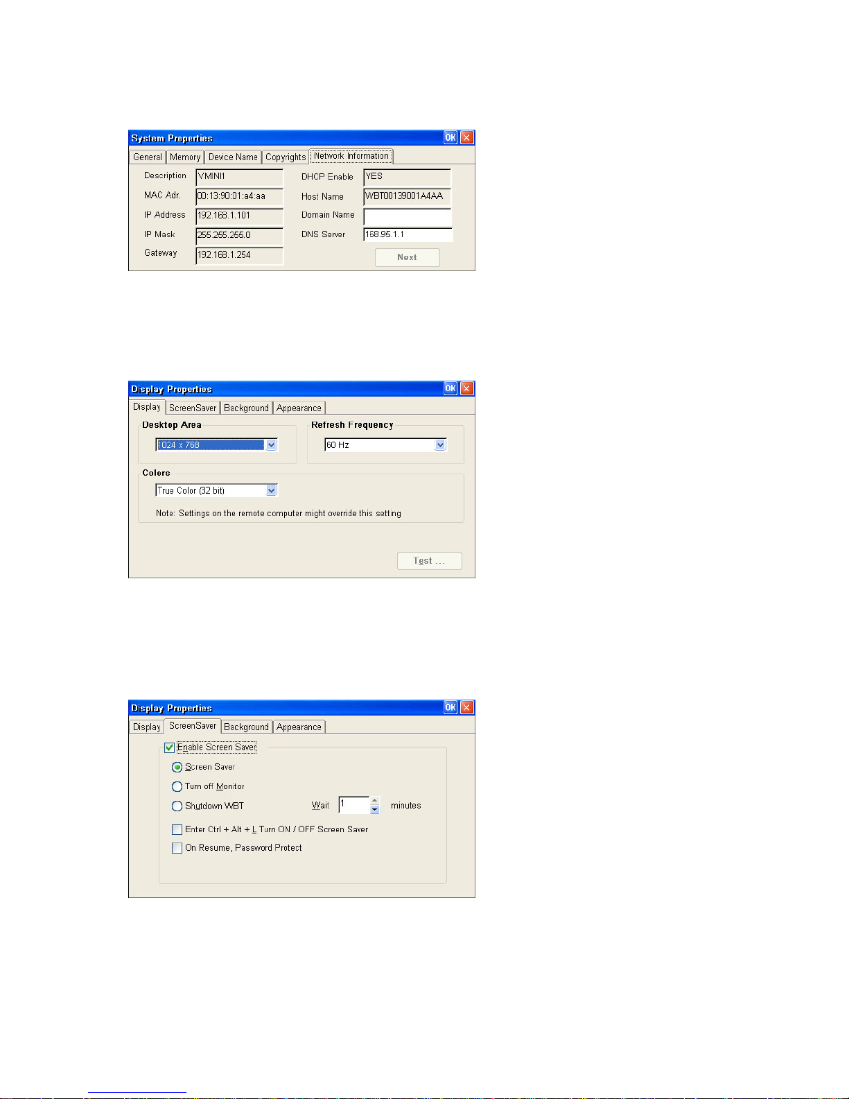
6.3.5 Network Information
By clicking on the “Network Information” icon, all the existing network information will be displayed.
6.4 Display
6.4.1 Display
The Display properties sheet lets you configure the terminal's display screen. Invoke this properties sheet by clicking on the
Display tab in the Terminal Properties dialog box. The following figure shows the properties sheet. You can also Test your
display after selecting one Refresh Frequency, the new testing mode will appear. The graphics adapter will be set to the new
mode temporarily for about 5 seconds so you can determine whether your display works properly.
6.4.2 Screensaver
Tick the “Enable Screen Saver” and you can configure your desired way to enable the screen saver for this WBT. T here are
three options to choose: Screen Saver, Turn Off Monitor and Turn Off W BT. You can leav e this WBT t o activate the function
automatically according to the time you set. Or you can tick “ Enab le Ctrl + Alt + L Turn ON/OFF screen saver” to manually
activate/deactivate any one of the left three energy savers you tick by pressing the hot-keys of “Ctrl + Alt + L”. “On Resume,
Password Protect” provide s more s ecurit y protection.
6.4.3 Background
____________________________
ADDS 5300 Win CE
80
Page 86
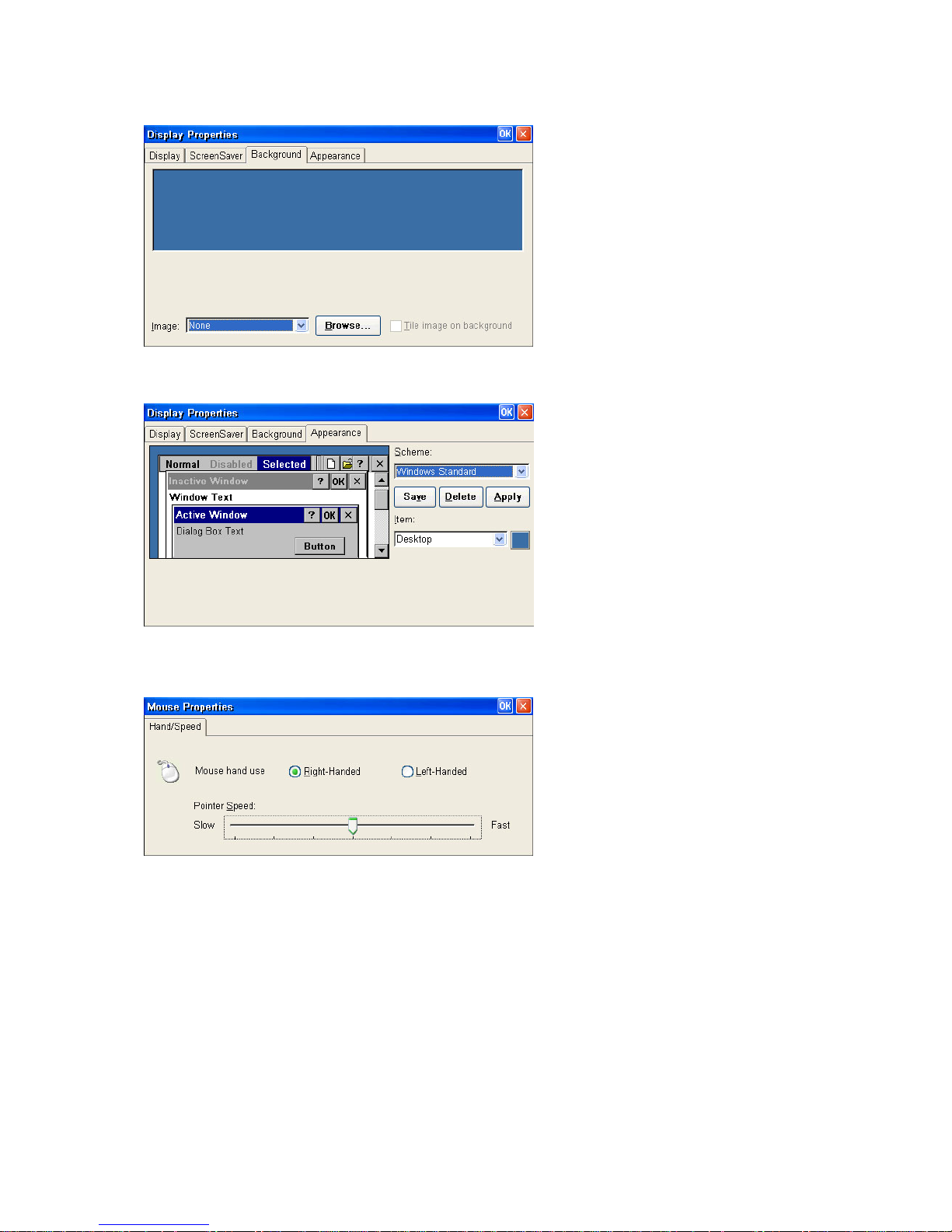
In the “Background”, users can change the Desktop background image.
6.4.4 Appearance
In the “Appearance”, Users can change the style of Appearance in the WBT.
6.5 Mouse
Click Mouse Properties if you want to configure your mouse setting to Right-Handed or Left-Handed, and the Pointer
Speed.
6.6 Sounds
The Sounds can adjust the Volume of the sounds of the client machine. Enable sounds for the events, applic ation and
notifications. Besides, users can set the sounds of events by their favorite sett ings .
____________________________
ADDS 5300 Win CE
81
Page 87
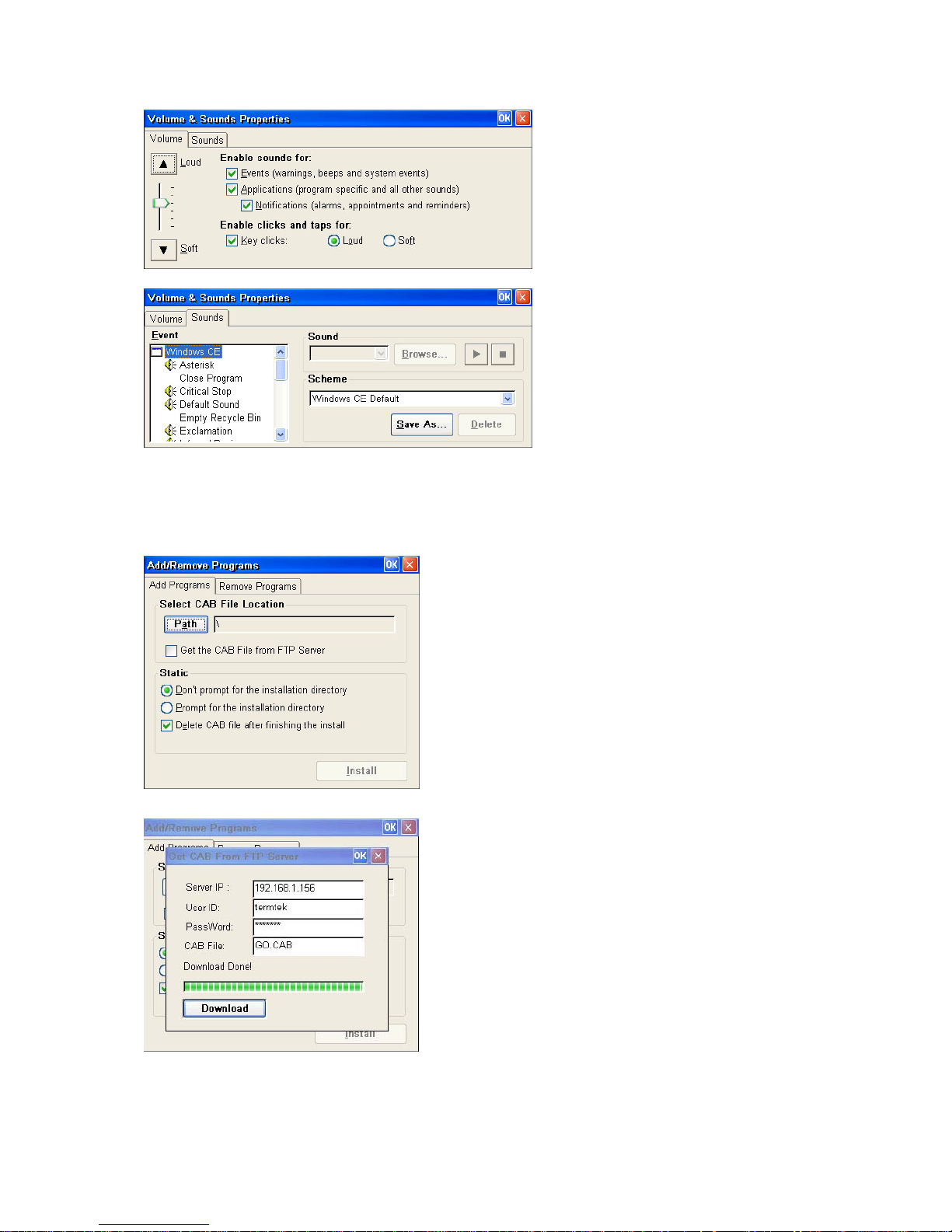
6.7 Add/Remove Programs
With the Add/Remove Programs, users can add programs that support windows CE packed in file type CAB, and remove
those programs installed by users.
6.7.1 Add Programs
Users can add programs that support windows CE packed in file type CAB.
Besides, users can get CAB file from FTP servers and then install.
6.7.2 Remove Programs
Users can remove programs installed by themselves that they do not need them any more.
____________________________
ADDS 5300 Win CE
82
Page 88
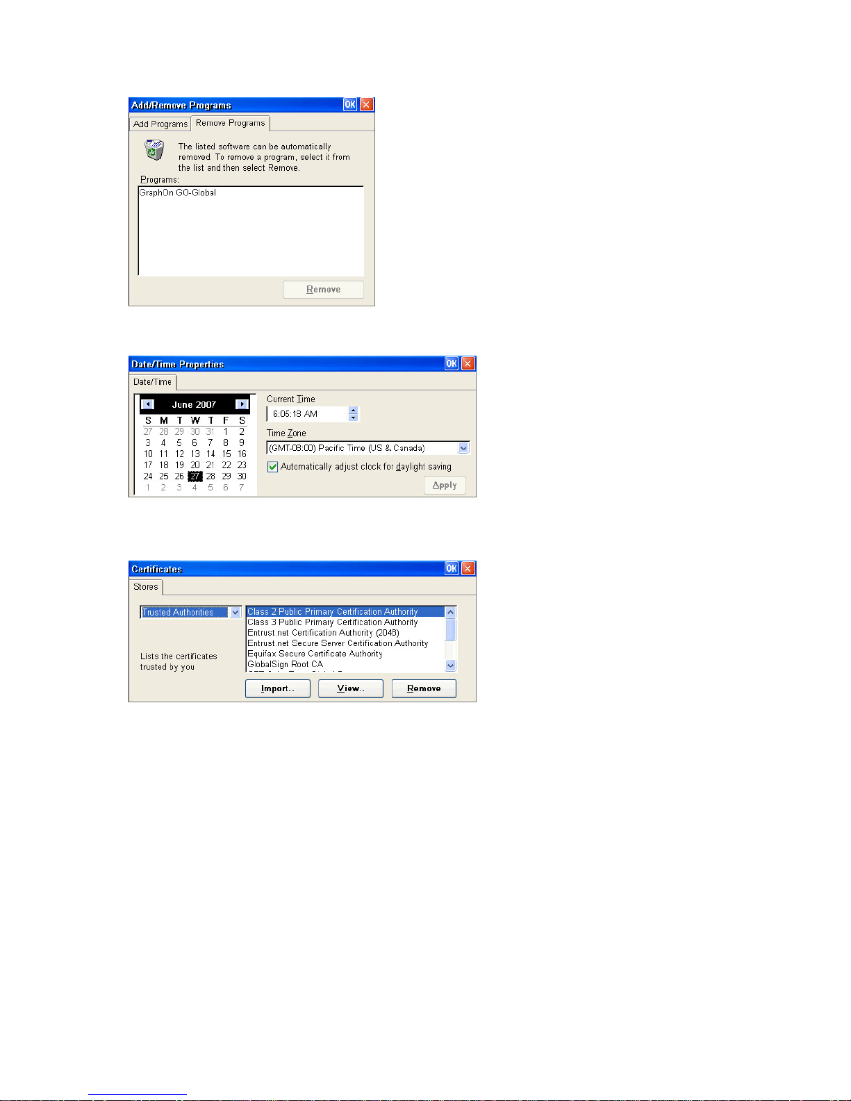
6.8 Date/Time
User can set up your local time for this device.
6.9 Certificates
Certificates are the basic component of Micros oft PKI. And the main purpose is to assure secret. Users can be grant ed
authorization to browse the web or to enter sever by getting certificates.
6.10 System Info
6.10.1 General
____________________________
ADDS 5300 Win CE
83
Page 89
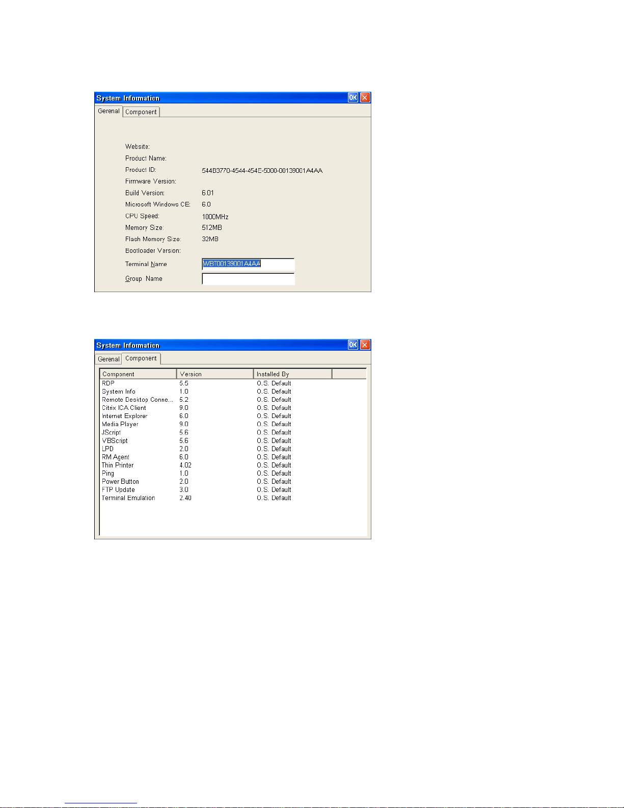
The General page describes all the general information about this WBT. Th e inf ormation may vary from tha t shown in abov e
figure.
6.10.2 Component
The Component page shows the important components and t he current version of these components included in the WBT
firmware.
6.11 Citrix ICA Configure
This section describes how to change settings that a pply for all connection entries on this WBT. It also desc ribes how to
____________________________
ADDS 5300 Win CE
84
Page 90

change the default settings that are used when creating new ICA connection entries. You may want to do this if you always
prefer to use a particular setting; for example, a sound quality that is different from the initial setting or a larger default
window size.
The Global ICA Client Settings dialog box contains the following tabs:
a. The Default Hotkeys tab, where you can define custom key combinations for system hotkeys. See “Configuring
Hotkeys” for more information.
b. The Preferences tab, where you can control the default window and settings used for new ICA connection entries. See
“Configuring Global Preferences” for more information.
c. The Server Location tab, where you can configure network protocol and server location options. See “Configuring
Network Protocol and Server Location” later in this section.
The Firewall Settings tab, where you can configure the client to use a SOCKS proxy, alternate address re-mapping
d.
and SSL Relay address. See “Configuring Firewall Settings” for more information about using the ICA Client with a
Firewall.
The PNLite Settings tab, where you can configure the client to switch from Remote Access Manager m ode to PNLite mode.
In PNLite mode, a list of available published applications on the network is published to the ICA client. This means the user
need not configure each connection entry manually. For more information about PNLite, see PNLite Mode.
6.11.1 Configuring Hotkeys
This WBT provides users with hotkeys that can be used during ICA sessions to control various functions. Some hotkeys
control the behavior of the ICA Windows-based Terminal Client itself while others emulate standard Windows hotkeys. When
you want to use a Microsoft Windows key combination during a session, use the mapped hotkey instead. The following table
lists the default ICA Windows-based Terminal Client hotkeys.
Default ICA WBT Client Hotkeys
Name
Connection
Status
Close Session CTRL+2 Disconnects the ICA Windows-based Terminal Client from the Citrix
Esc CTRL+3 Alternately hides and displays the ICA session window.
CTRL-ALT-DEL CTRL+4 Displays the Windows NT Security dialog box on the Citrix server.
CTRL-ESC CTRL+5 On MetaFrame servers, the Windows Start menu is displayed. On
ALT-ESC CTRL+7 This hot ke y cycles the focus through the minimi zed icon s and open
ALT-TAB CTRL+8 This hotke y cycles through all applications in the ICA session. A
ALT-BACKTAB CTRL+9 Like the ALT+TAB hotkey, this key sequence cycles through
To Change the Default Hotkeys
Default
Value
CTRL+6 Displays ICA Client connection status.
Description
server and closes the client window on the local desktop. Using this
hotkey leaves the ICA session running in a disconnected state on the
Citrix server. If you do not want to leave your session running in a
disconnected state, log off instead.
INFRAME servers, this hotkey displays the Task List.
W
windows of applications run in your ICA session.
pop-up box appears and displays the programs as you cycle through
them. The selected application receives keyboard and mouse focus.
applications that have been opened in the ICA session, but in the
opposite direction. The chosen application receives keyboard and
mouse focus.
____________________________
ADDS 5300 Win CE
85
Page 91
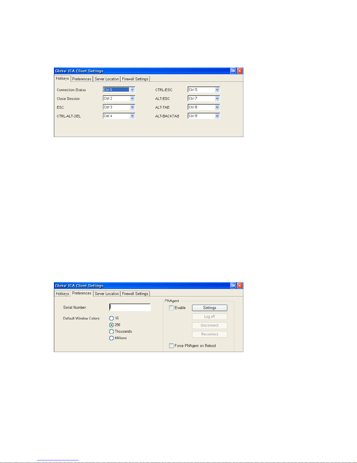
a. Click on the icon of Global ICA Client Settings and the dialog box will appear as below.
b. On the Hotkeys page, use the lists of keys to customize the default hotkey key sequences.
c. Click OK to save your changes.
d. Make the desired changes.
Click OK to save your changes.
e.
6.11.2 Configuring Global Preferences
The following settings are configured in the global Preferences tab:
9 Default Window Colors: In the Window Colors box, select 16,256, Thousands or Millions colors by clicking the
appropriate radio button. When using a low-bandwidth connection, 16-color mode may provide better perform ance.
This WBT can support up to Millions colors that is superior to other WBTs in the mark et.
9 Serial Number. This is the serial number of your ICA Client software. This number is only necessary when you are
using the ICA Windows-based Terminal Client with a product such as W
ICA Client to have a Citrix PC Client Pack serial number. If a serial n umber is required, you must enter it exactly as it
appears on the Serial Number card. The serial number is not used when connecting to MetaFrame servers.
9 Client Name. This box allows you to set the name of your client device. Citrix servers use the client name to uniquely
identify resources (such as mapped printers) associated with a given client device. The client name should be u nique
for each computer running a Citrix ICA Client. If you do not use unique c lient names, device mapping and appli cation
publishing may not operate correctly.
To Change the Default Global Preferences for All ICA Connection Entry
a. Click the Preferences tab.
INFRAME Host/Terminal, which requires each
b. Make the desired changes.
c. Click OK to save your changes.
6.11.3 Server Location
____________________________
ADDS 5300 Win CE
86
Page 92
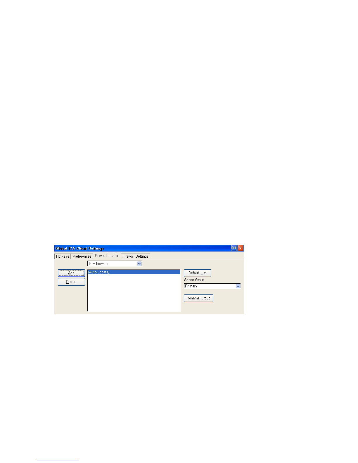
This section explains how to:
a. Set the protocol the ICA clients uses
b. Control the way in which the ICA client locates Citrix servers
c. Configure a list of Citrix servers for Business Recovery
The network protocol settings allow you to control the way the ICA client searches for Citrix server and how it communicates
with them. Server location (also called server browsing) provides a method for a user at a network-connected ICA Client to
view a list of all Citrix servers on the network that have ICA connections configured, and a list of all published applications.
The way in which server location works depends on which network protocol has been configured:
9 TCP/IP – The client uses the UDP protocol to search for Citrix servers. The client communicates with the Citrix server
using ICA protocol over TCP/IP. This is the default protocol.
9 TCP/IP + HTTP – The client uses the HTTP protocol to locate Cit rix servers . The client communicates with the Citrix
server using ICA protocol over TCP/IP. Select this option when using the ICA Client over the Internet or via a firewall
or proxy server.
9 SS L + HTTPS – The client uses the HTTPS protocol to search for a list of Citrix servers. The client comm unic ates with
the Citrix server using ICA with SSL. SSL+HTTPS provides strong encryption of ICA traffic and Citrix server
authentication. Select this option when using the ICA Client over the Internet or via a firewall or proxy server.
The TCP/IP+HTTP and SSL+HTTPS protocols can only be used with compatible Citrix servers. Check the Citrix
server administrator’s guide for further information.
When the CTP/IP or TCP/IP+HTTP protocols are selected, the ICA protocol can be encrypted using SecureICA.
Business recovery provides consistent connections to published applications in the event of a master ICA Browser server
disruption. You can define up to three groups of Citrix servers to which you want to connect: a primary and two backups.
Each group can contain from one to five servers.
When you build a new ICA connection, the ICA client in this WBT will automatically search for any Citrix server on the
network. The default setting is TCP browser but you can make desired change at this page. It depends on what kind of
protocol of your Citrix server. If you can’t find by this protocol, scroll through the list and try other protocols. This will change
the default protocol setting of ICA client when searching for Citrix server location.
6.11.4 Firewall Settings
____________________________
ADDS 5300 Win CE
87
Page 93
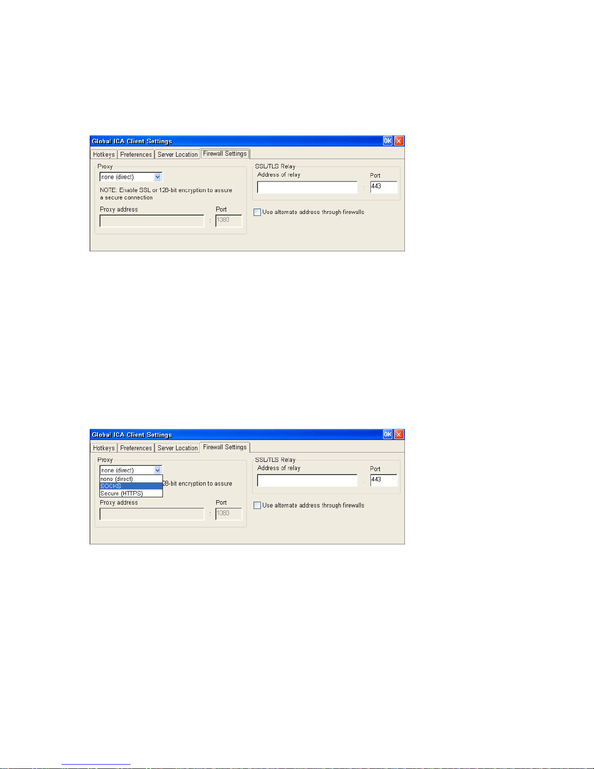
This is to configure a default SOCKS proxy server, if you would like to configure a SOCKS proxy server for a specific ICA
connection entry, please refer to the description mentioned earlier in section 4.5.3.
To Configure a Default SOCKS Proxy Server
a. Tick Connect via SOCKS proxy.
b. In the Address of proxy to use box, enter the SOCKS proxy server’s IP address.
c. In the Port box, enter the proxy server's port number (if different than 1080).
d. Click OK to save your changes.
a. If you configure a default SOCKS proxy server, you must specify at least one server in the Server Location tab for
server and published application browsing to work.
Configuring Alternate Address Translation
If the ICA Client is outside a firewall that uses address re-mapping, you must configure the ICA Client t o use the alternate
address returned by the master ICA Browser. This is necessary even if you are not using a SOCKS proxy server.
b. You must also use the ALTADDR ut ility to manually set the alternate address for each Citrix server, See the Com mand
Reference appendix of either the MetaFrame Administrator’s Guide or the W
information.
c. If you set alternate address translation for all connection entries, it cannot be disabled for specific connection entries.
INFRAME System Guide for more
To Use Alternate Address Translation for All Connection Entries
a. Press F2 to enter the Terminal Properties page, click Apps tab and then click Global ICA Client Settings icon.
b. Click the Firewall Settings tab.
c. Click Use alternate address for firewall connection.
d. Click OK to save your changes.
____________________________
ADDS 5300 Win CE
88
Page 94
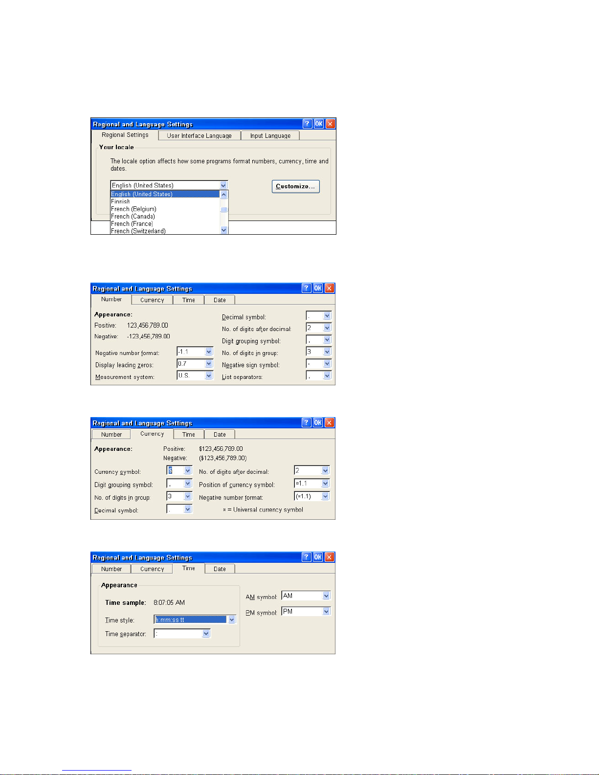
6.12 Regional Settings
6.12.1 Regional Settings
Set up the keyboard locale for the local device.
Following shows how to customize the Regional Settings
6.12.1.1 Number
Press the Customize the Number; Currency, Time and Date pages will appear.
There are different types to display the numbers in the settings, however,
it will be shown according to what keyboard locale you have set up.
6.12.1.2 Currency
This currency model will also be displayed according to the locale you have set up.
6.12.1.3 Time
Time could be arranged by turns of hours, minutes and sounds.
____________________________
ADDS 5300 Win CE
89
Page 95
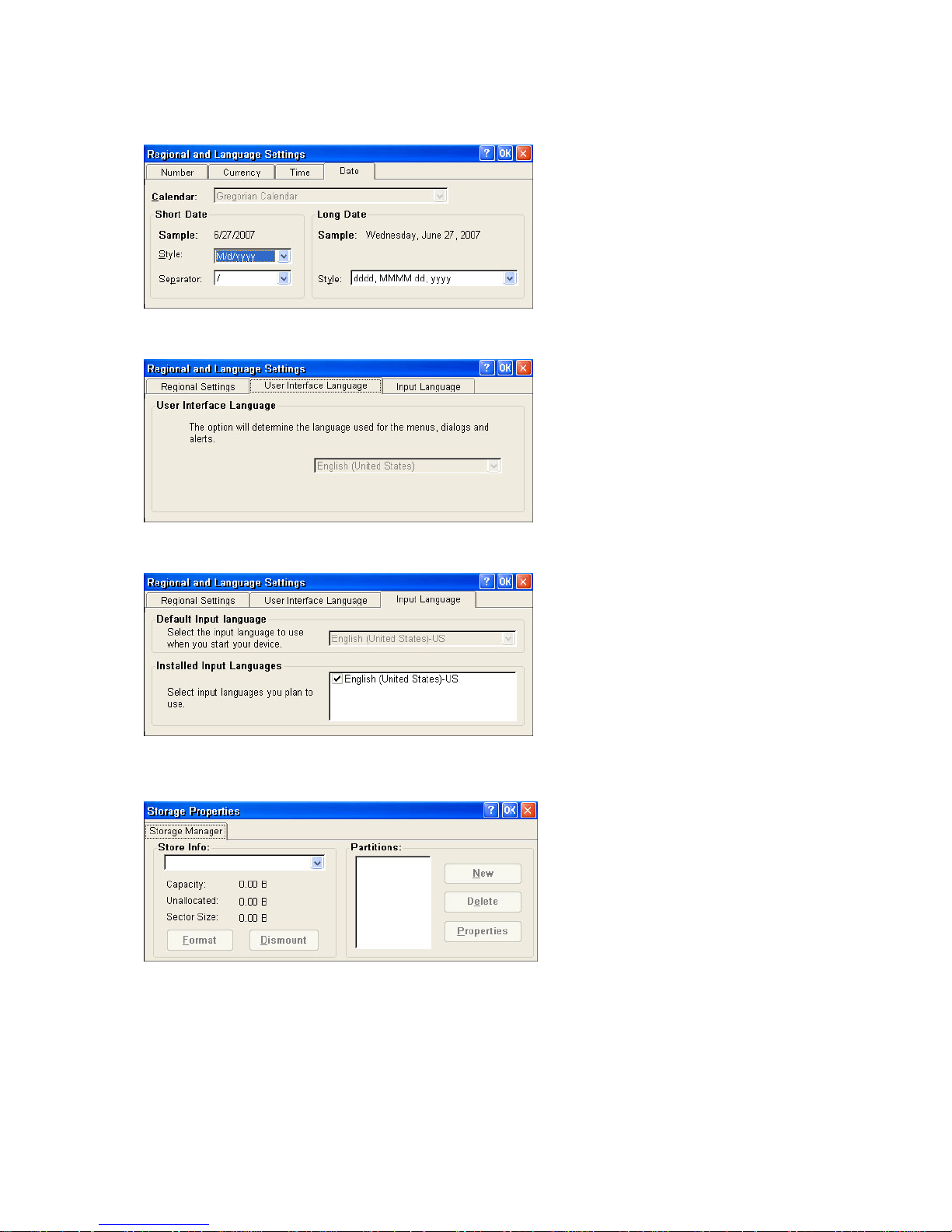
6.12.1.4 Date
How you would like to show the date at the client side could be arranged here.
6.12.2 User Interface Language
Determine the language used for the menus, dialogs, and alerts.
6.12.3 Input Language
Set up the Input Language for the local device, and you can also select the input language you plan to use.
6.13 Storage Manager
If the machine is connected with any floppy or Hard drivers, it will show the storage information.
User can also format or do the partitions to this local storage device.
____________________________
ADDS 5300 Win CE
90
Page 96
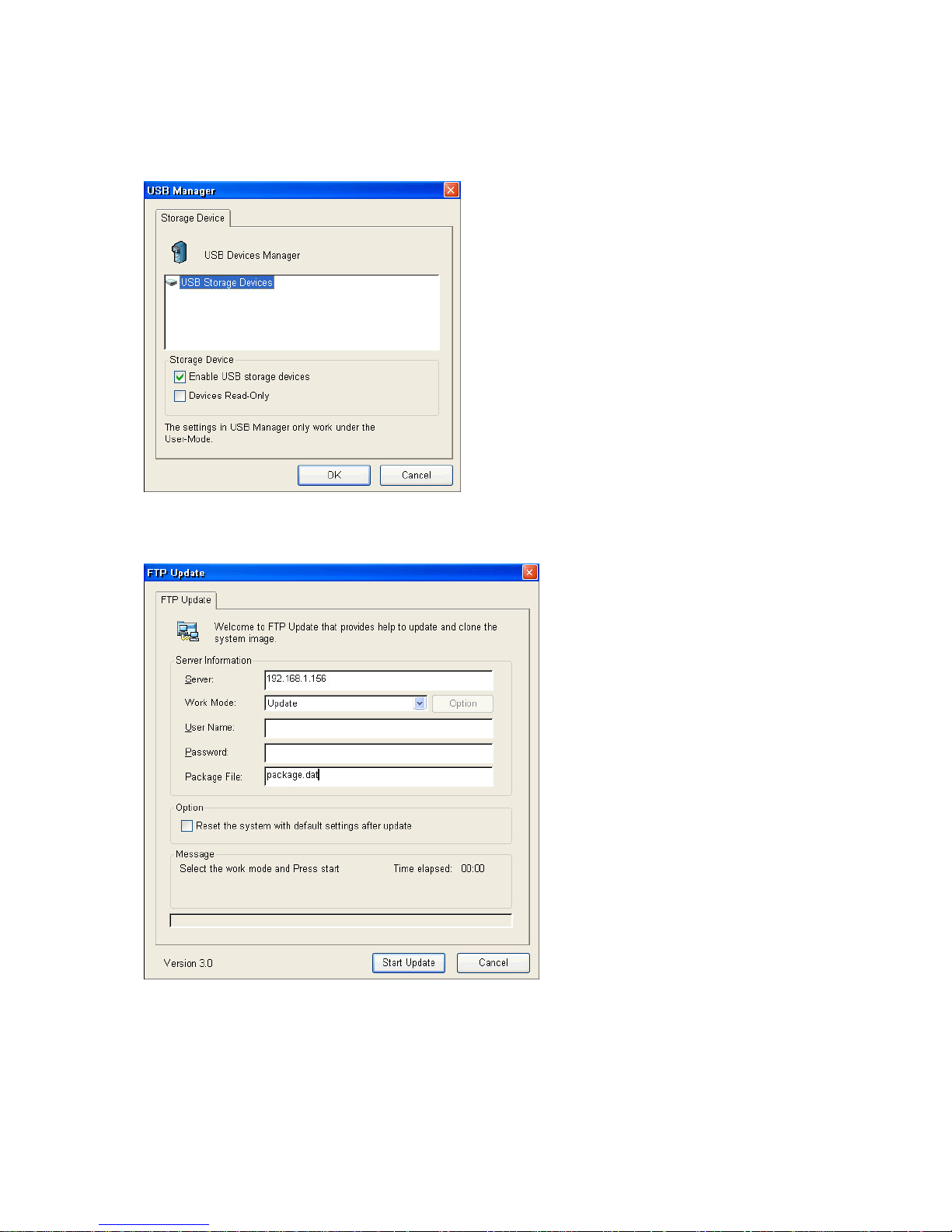
6.14 USB Manager
The USB Manage r provides management of USB Storage Devices. One can see and enable or disable the USB Storage
Devices connecting to the WBT. And one can set all USB Storage Devices as Read-only to prevent losing of data.
6.15 FTP Update
The FTP Update provide the ability to Update and Back-up the firmware, logo, register, and company information with
remote FTP servers.
____________________________
ADDS 5300 Win CE
91
Page 97
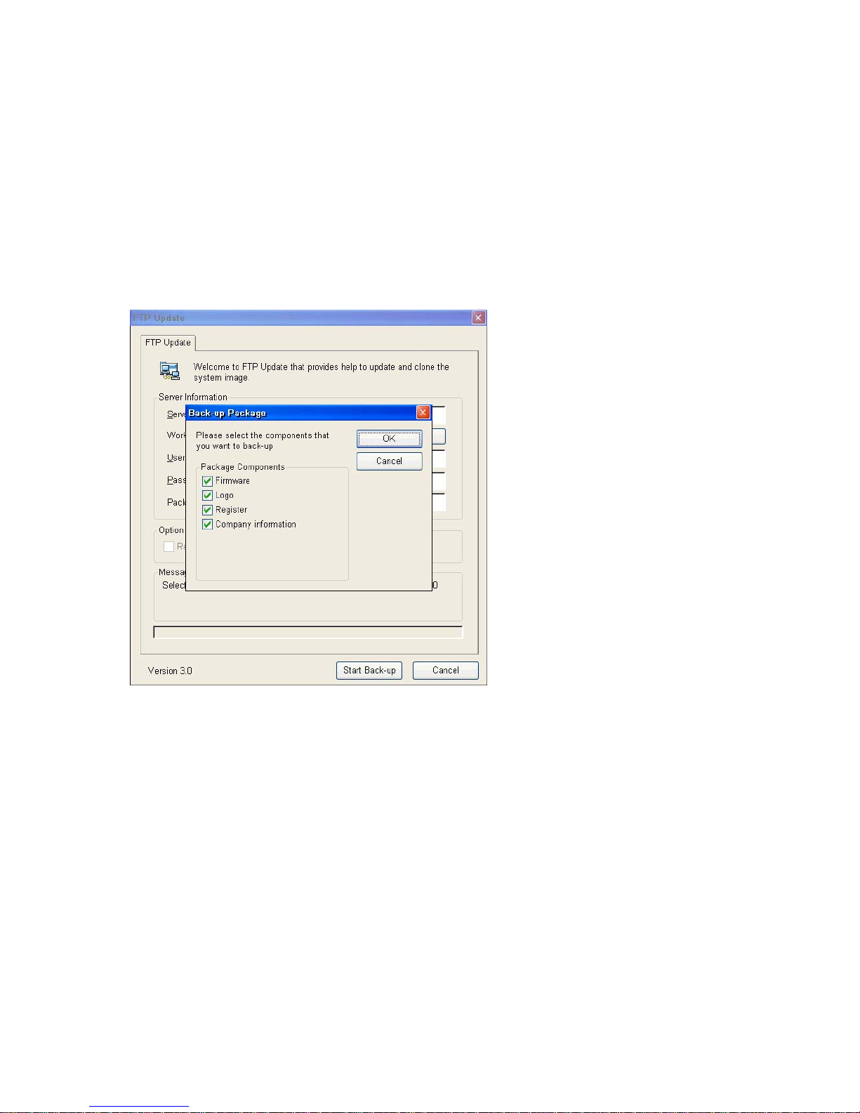
6.15.1 Update
The Work-Mode Update lets you update new firmware, registers, logo, and company information. Key in Server Name, File
Name, User ID and Password and Click Start Update button, the update Status will be show in the Status Window.
Note 1. All new FTP Update with version 3.0 cannot update the WBT with the update d ata provide for elder FTP Update
version. The FTP Update with version 3.0 updates the WBT with package file. The package file consists of
various firmware, logo, register, and company information data. One can generate a package file by the
Work-Mode Back-up provided by the FTP Update
6.15.2 Back-up
The Work-Mode Back-up lets you back-up the firmware, register, logo, and company information in the WBT. To use the
back-up function, select the work-mode as Back-up, and press Start Backup button. In default, the FTP Update will
back-up firmware, registers, logo, and company information. If one just wants to back-up certain components, press Option
to select the components that he want.
____________________________
ADDS 5300 Win CE
92
Page 98
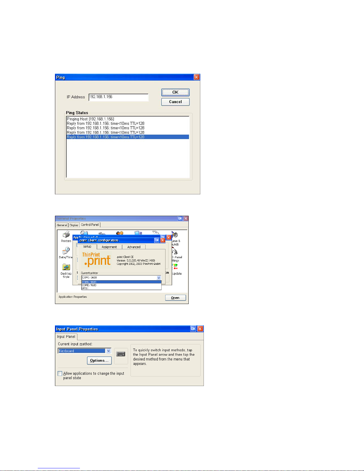
6.16 Ping
The Ping Test Settings sheet lets you ping the IP address to make sure it’s on the network. Invoke this setting by clicking
on the Ping icon of Terminal Properties dialog box. The following figure shows the Ping function tag, just type in the IP
address you want to ping and click OK.
6.17 Thin Printer
You can tick “Enable ThinPrint” to use ThinPr int func tio n in RDP or ICA.
6.18 Input Panel
The Input Panel allows users to switch current input method and configure the input methods.
6.19 LPD
____________________________
ADDS 5300 Win CE
93
Page 99
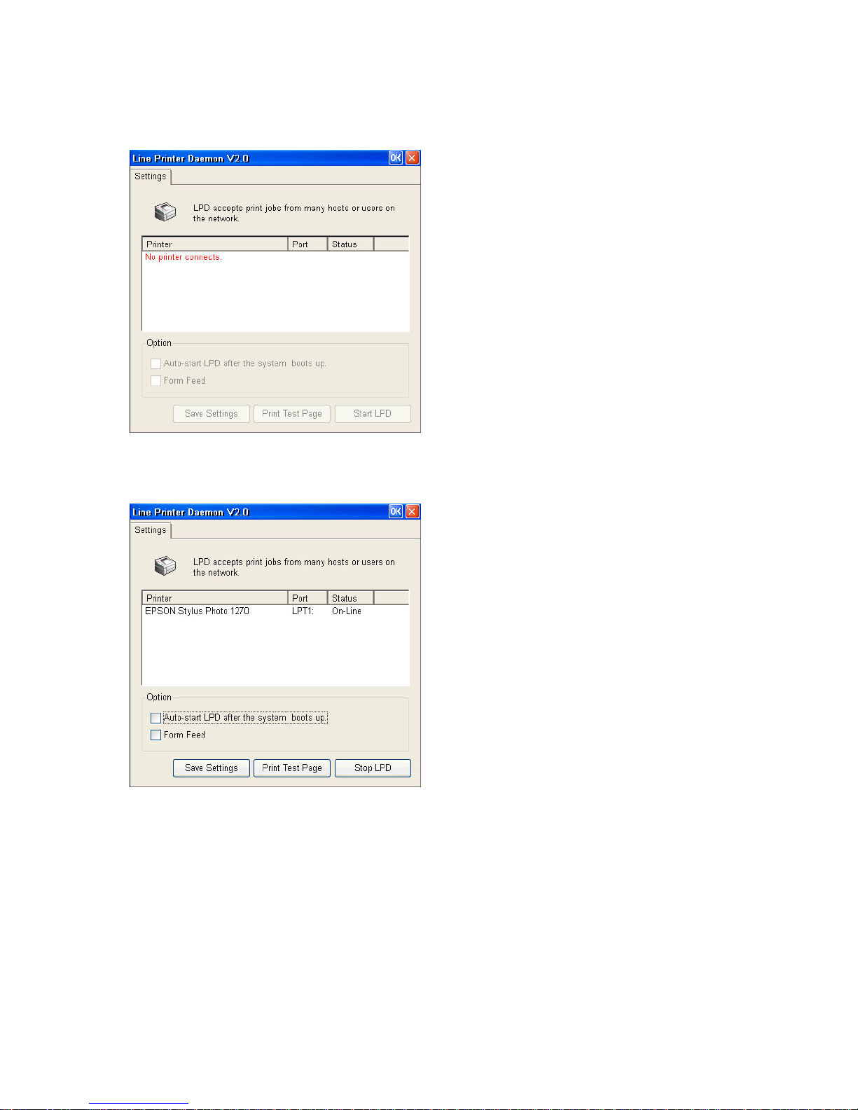
This WBT with WIN CE.NET offers another way of through LPD protocol to sen d the print j ob. LPD is a bu ilt-in
printing prot ocol in t he BSD t ype of UNI X. However, it is also available in most UNIX system. With LPD, users
can using UNIX machine for printing purpose or any machine which supports LPD protocol.
6.19.1 Setup for LPD
In the page, user can select the printers connecting to the WBT. Select one of them and press “Start LPD” and then the LPD
will keep stand-by. Users do not need to reboot the WBT.
____________________________
ADDS 5300 Win CE
94
Page 100
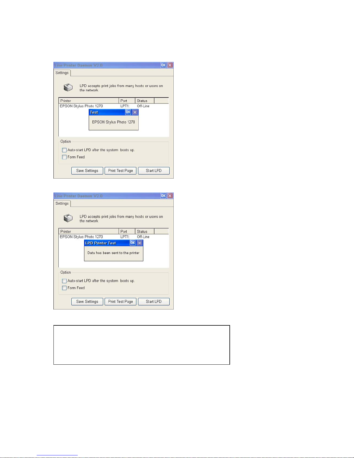
User can press “Print Test Page” button to check if the printer has connected completely as user settin g. If connected
completely the printer type name will appear on the screen. For example: the connected printer is EPSON Stylus Photo
1270.
Click “OK” to process Test procedure and the WBT will notify user that “the test data has been sent to the printer”.
Checking the printer then user can find the default characters printed as below.
LPD for CE 6.0 version 2.0
==========================================================
EPSO N Stylus Photo 1270(s hows the printer model name as user setup)
The quick brown fox jump over the lazy dog.
When the LPD stands by, users can press “Stop LPD” to stop it. If you need the LPD start automatically when the WBT
boots up, click the “Auto-start LPD after the system boots up” and press “Save Settings” or “OK”. When the WBT reboot
next time, the LPD will start up automatically.
____________________________
ADDS 5300 Win CE
95
 Loading...