

Page 1

ADDS 4000
User’s Guide
Page 2

Before using this information and the product it supports, be sure to read the general
information under “Notices.”
It is the policy of Boundless Technologies, Inc. to improve products as new technology, components,
software, and firmware become available. Boundless Technologies, therefore, reserves the right to
change specifications without prior notice.
All features, functions, and operations described herein may not be marketed by Boundless
Technologies in all parts of the world. In some instances, photographs are of equipment prototypes.
Therefore, before using this document, consult your Boundless Technologies representative or Boundless
Technologies office for information that is applicable and current.
Note that Boundless Technologies appreciates receiving suggestions and comments on its publications.
After reading this guide, please comment and return the comment sheet that has been provided.
Copyright © Boundless Technologies, Inc. 2007.
Farmingdale, New York
All rights reserved.
Printed in USA
Page 3

1
This guide...
is a user’s manual and contains all of the information necessary to install, setup, and use
the 4000 product.
More detailed information on programming using control codes and escape sequences,
default strings and character sets, international language support, etc. can be obtained
by calling:
USA and Canada calls . . . . 1-800-231-5445
International calls . . . . . . . 1-631-962-1500
At the options menu, press 2 for “Product Information,” then press 2 for “Products or
Program Information Mailed to You,” and request the following:
4000 Guide to Operations, part number 598-0011161
This manual is offered to our customers at no additional charge. When calling to
order, please have your terminal’s serial number available.
Page 4

Page 5

chapter
1
Contents
Preface v
How to Connect/Disconnect the Terminal.................................................... vi
Notices............................................................................................... vii
Trademarks and Service Marks ..................................................................vii
Electronic Emission Notices.................................................................... viii
Safety Notices ........................................................................................ x
Introduction 1
Features................................................................................................ 2
Compatibility ................................................................................. 2
Display .......................................................................................... 2
Character Sets.................................................................................. 2
Communications ............................................................................. 3
Keyboards...................................................................................... 3
Desk Accessories .............................................................................. 3
Physical Features..................................................................................... 4
Keyboards............................................................................................. 5
Usage Notes ........................................................................................... 7
Communications .................................................................................... 8
Flow Control ...................................................................................8
Host Port 1 ..................................................................................... 9
Host/Printer Port 2 ........................................................................ 10
Parallel Printer Port......................................................................... 11
Terminal to Modem (DCE) or Host..................................................... 11
Terminal to Host (DTE) or Printer...................................................... 12
Screen Display and Pages......................................................................... 12
Bottom Status/Label Line Display...................................................... 12
Installation 13
i
Page 6

ii Contents
STEP 1 – Know Your Devices.................................................................. 13
STEP 2 – Physical Connections................................................................. 14
STEP 3 – No Printer Option .................................................................... 14
STEP 4 – Know Your Serial Port(s) Protocol................................................ 14
STEP 5 – Communications Setup Selections ................................................ 15
Connection A: Host DCE................................................................. 15
Connection B: Host DTE................................................................. 15
Connection C: RS-232 with Modem................................................... 16
Connection D: RS-232-C with Modem ............................................... 16
Connection E: RS-232-C Printer........................................................ 16
Connections F and G: Parallel Printer.................................................. 16
STEP 6 – Emulation Setup Selection.......................................................... 16
STEP 7 – Additional Setup Options........................................................... 16
STEP 8 – Save Parameters ....................................................................... 17
STEP 9 – Establish Communications.......................................................... 17
Host/Printer Connection Guide................................................................ 18
Setup 21
Overview ............................................................................................ 21
Setup Menu .................................................................................. 21
Cursor Keys trokes for Movement Within the Setup Menu.........................22
EXECute Menu .................................................................................... 23
GLOBAL Menu.................................................................................... 24
COMMunications Menu (Sess 1 - EIA) ....................................................... 25
AUXiliary/COMMunications Menu (Sess 2 - AUX) ...................................... 27
KEYBOARD Menu............................................................................... 29
SCREEN Menu..................................................................................... 31
VISUAL Menu ..................................................................................... 32
MODE Menu....................................................................................... 33
TAB Menu .......................................................................................... 34
FUNCTion Key Menu............................................................................ 35
BELL Menu......................................................................................... 38
Desk Accessories 39
Clock.................................................................................................. 39
Calendar.............................................................................................. 41
Calculator (ASCII Keyboard) .................................................................... 42
How To Use: ................................................................................. 42
Calculator (PC/+ Keyboard)..................................................................... 43
How To Use: ................................................................................. 43
ASCII Chart ......................................................................................... 44
Page 7

Contents iii
Appendix 45
Local Hot Keys..................................................................................... 45
Page 8

Page 9

1
Preface
This product is in conformity with the protection requirements of EU Council
Directive 89/336/EEC on the approximation of the laws of the Member States
relating to electromagnetic compatibility.
Boundless Technologies cannot accept responsibility for any failure to satisfy the
protection requirements resulting from a non-recommended modification of the
product, including the fitting of non- Boundless Technologies option cards.
v
Page 10
vi Preface
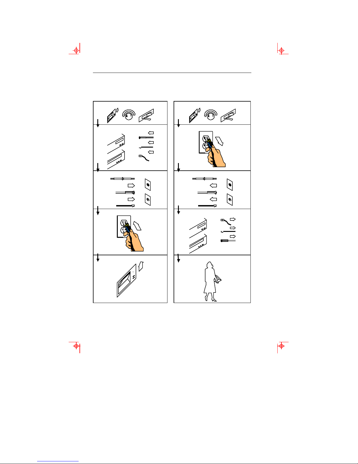
How to Connect/Disconnect the Terminal
To Connect: To Disconnect:
First, turn everything OFF.
First, turn everything OFF.
Attach all cables to devices.
Attach signal cables to receptacles.
Attach power cord to outlet.
Turn device ON.
Remove power cord from outlet.
Remove signal cables from receptacles.
Remove all cables from devices.
You may now take it with you.
Note: In the UK, by law, the telephone cable
must be connected after the power cord.
Note: In the UK, by law, the power cord must
be disconnected after the telephone line cable.
Page 11

Notices
References in this publication to Boundless Technologies products, programs, or
services do not imply that Boundless Technologies intends to make these available to
all countries in which Boundless Technologies operates. Any reference to an Boundless
Technologies product, program, or service is not intended to state or imply that only
Boundless Technologies product, program, or service may be used. Any functionally
equivalent product, program, or service that does not infringe any of Boundless
Technologies’ intellectual property rights may be used instead of Boundless
Technologies product, program, or service. Evaluation and verification of operation
in conjunction with other products, except those expressly designated by Boundless
Technologies, are the user’s responsibility.
This publication could contain technical inaccuracies or typographical errors.
This publication may refer to products that are announced but are not currently
available in your country. Boundless Technologies makes no commitment to make
available any unannounced products referred to herein. The final decision to
announce any product is based on Boundless Technologies’ business and technical
judgment.
The drawings and specifications contained herein shall not be reproduced in whole or
in part without the written permission of Boundless Technologies.
Trademarks and Service Marks
The following terms are trademarks of these companies:
CSA Canadian Standards Association
Hazeltine 1500 Esprit
DEC VT-52/100 Digital Equipment Corporation
WYSE 50/75 Wyse Technology
TVI 910, 920, 925 TeleVideo Systems, Inc.
ADDS Viewpoint, Regent 40 Boundless Technologies, Inc.
Notices vii
Page 12

viii Preface
Electronic Emission Notices
Federal Communication Commission (FCC) Statement
Note: This equipment has been tested and found to comply with the limits for a Class
A digital device, pursuant to Part 15 of the FCC Rules. These limits are designed to
provide reasonable protection against harmful interference when the equipment is
operated in a commercial environment. This equipment generates, uses, and can
radiate radio frequency energy and, if not installed and used in accordance with the
instruction manual, may cause harmful interference to radio communications.
Operation of this equipment in a residential area is likely to cause harmful
interference, in which case the user will be required to correct the interference at his
own expense.
Properly shielded and grounded cables and connectors must be used in order to meet
FCC emission limits. Boundless Technologies is not responsible for any radio or
television interference caused by using other than recommended cables and connectors
or by unauthorized changes or modifications to this equipment. Unauthorized
changes or modifications could void the user's authority to operate the equipment.
This device complies with Part 15 or the FCC Rules. Operation is subject to the
following two conditions: (1) this device may not cause harmful interference, and (2)
this device must accept any interference received, including interference that may
cause undesired operation.
Canadian Department of Communications Compliance Statement
This equipment does not exceed Class A limits per radio noise emissions for digital
apparatus, set out in the Radio Interference Regulation of the Canadian Department of
Communications.
Avis de conformité aux normes du ministère des Communications du Canada
Cet équipement ne dépasse pas les limites de Classe A d'émission de bruits
radioélectriques pour les appareils numériques, telles que prescrites par le Règlement sur
le brouillage radioélectrique établi par le ministère des Communications du Canada.
Page 13

Electronic Emission Notices ix
Japanese Voluntary Control Council for Interference (VCCI) Statement
This equipment is Class 1 Equipment (information equipment to be used in
commercial and industrial districts) which is in conformance with the standard set by
Voluntary Control for Interference by Data Processing Equipment and Electronic
Office Machines (VCCI) with an aim to prevent radio interference in commercial and
industrial districts.
This equipment could cause interference to radio and televis ion receivers when used in
and around residential districts.
Please handle the equipment properly according to the instruction manual.
Korean Government Ministry of Communication (MOC) Statement
Please note that this device has been approved for business purposes with regard to
electromagnetic interference. If you find this is not suitable for your use, you may
exchange it for a non-business purpose one.
Page 14
x Preface
Safety Notices
Danger Notices
A danger notice indicates a hazard that could possibly cause death or serious personal
injury.
The following danger notices are used throughout this manual.
DANGER: To prevent a possible electrical shock when installing the device, ensure
that the power cord for that device is unplugged before installing signal cables.
DANGER: To prevent a possible electrical shock when adding the device to a
system, disconnect all power cords, if possible, from the existing system before
connecting the signal cable to that device.
DANGER: To prevent a possible electrical shock during an electrical storm, do not
connect or disconnect cables or station protectors for communication lines, display
stations, printers, or telephones.
DANGER: To prevent a possible electrical shock from touching two surfaces with
different electrical grounds, use one hand, when possible, to connect or disconnect
signal cables.
DANGER: To avoid a shock hazard:
þ The power cord must be connected to a properly wired and earthed receptacle.
þ Any equipment to which this product will be attached must also be connected
to properly wired receptacles.
Page 15
Safety Notices xi
DANGER: Electrical current from power, telephone, and communication cables is
hazardous. To avoid shock hazard, connect and disconnect cables as shown on the
following page when installing, moving, or opening the covers of this product or
attached devices.
DANGER: The device’s switch is not the main disconnect. The device’s main
power disconnect is the detachable line cord.
Caution Notice
A caution notice indicates a hazard that could possible cause minor personal injury.
CAUTION: This product contains a lithium battery. Do not attempt to exchange or
charge the battery. Discard the product as instructed by local regulations for limited
lithium batteries. Do not burn.
Warning Notice
A warning notice indicates the possibility of damage to a program, device, system, or
data.
Page 16
chapter
1
Introduction
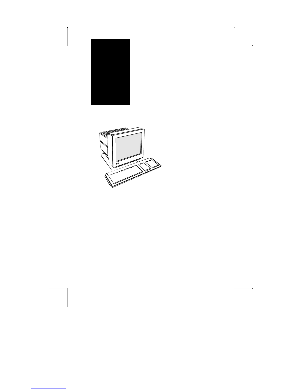
This terminal can emulate a number of
ASCII and ANSI terminals, including
PC-Term. The keyboards supported by
the terminal are the 101/102 key
Extended-PC (EPC), the 106/107
PC/+, and the ASCII keyboards.
The dual host capability of the terminal
allows you to run two different
applications simultaneously.
Clock, calendar, calculator, ASCII chart,
and diagnostic desk accessories are
provided. Another feature is the selectable
overscan border which can provide bezelto-bezel video.
This terminal also features an easy-touse Setup menu. Travel between
menus is facilitated by function keys,
the first letter of the menu name, or
the ENTER and SHIFT-ENTER keys.
1
Page 17

2 Introduction
Features
Compatibility
þ ADDS-Viewpoint™
þ Regent 40
þ Hazeltine™ 1500
þ Wyse™ 50, Wyse 75
þ DEC™ VT-52 & VT-100
þ PC Terminal
þ TVI™- 910, 920, 925
Display
þ 100 Hz refresh rate (flicker-free)
þ Selectable overscan borders
þ Selectable screen saver
þ 26 or 44 row display with top and bottom status lines
þ 80 or 132 column display
þ Double high/double wide display
þ Up to 2 pages of memory
þ Small footprint, tilt and swivel base
Character Sets
þ Numerous standard, graphic, and supplemental character sets
þ Support for different keyboard languages: US (English), UK (English), Danish,
French, German, Norwegian, Portuguese, Spanish, Swedish, Dutch,
Belgian-Flemish, French-Canadian, Italian, Latin American, Swiss-French,
Swiss-German
Page 18

Features 3
Communications
þ Serial RS-232-C host/printer port 1, operating from 110 to 38,400 baud
þ Serial RS-232-C host/printer port 2, operating from 110 to 19,200 baud
þ Parallel IBM™/Centronics™ compatible printer port
Keyboards
þ EPC 101/102-key keyboard for use in the US and Internationally
þ ASCII keyboard
þ PC/+ 106/107-key keyboard for use in the US and Internationally
þ Up to 35 shiftable and programmable edit and function keys
Desk Accessories
þ Calculator capable of transmitting results
þ Monthly Calendar
þ Clock with alarm settings
þ ASCII and Diagnostic charts
Page 19
4 Introduction
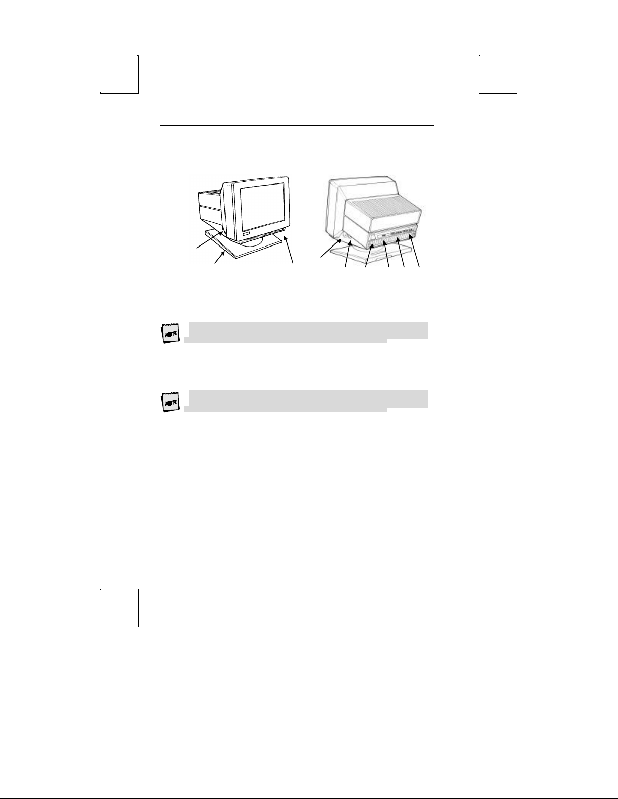
Physical Features
1
2 3
1. Keyboard Connector – push in the keyboard connector here.
2. Tilt and Swivel Base – use the tilt and swivel arrangement to adjust the viewing
angle. Grasp the lower corners of the terminal and push up or down, or twist left
or right.
3. Power Switch – “0” is off; “1” is on.
Leave the terminal’s power switch in the off position (“0”) until power, keyboard,
and communication connections are made.
4. Contrast Dial - adjust the contrast between characters of different intensities by
rotating the dial.
5. Brightness Dial – adjust the overall screen brightness by rotating the dial.
6. Power Connection – plug the female end of the power cord into this connector
and the male end of the cord into a properly grounded receptacle.
The Canadian Standards Association (CSA) recomme nds that the power outlet be
near the terminal and easily accessible at all times.
7. Parallel Printer Port – connect the cable from the IBM/Centronics compatible
parallel printer to this port. See the Installation chapter for options.
8. Printer Port – connect the cable from a serial printer here. See the Installation
chapter for options.
9. Host Port – connect the cable from the host here. See the Installation chapter for
options.
4
5 6 7 8 9
Page 20
Keyboards
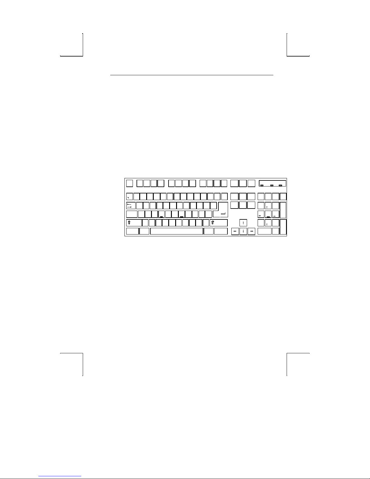
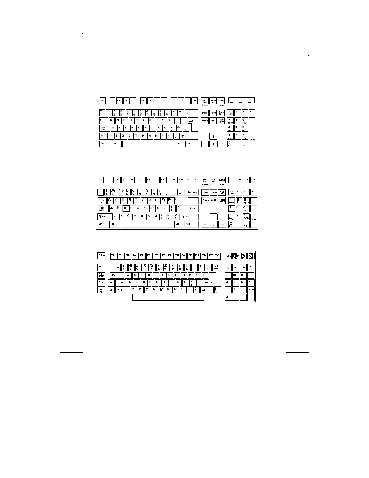
The “PC” keyboards, including the EPC (101/102-key) and the PC/+ (106/107key), are similar in style and feature a number of key groups.
The alphanumeric keypad is the main typewriter keypad, while the function key
group lies along the top of the keyboard and can be programmed locally or downloaded
from the host. The numeric keypad is the calculator-style set of keys on the right-hand
side of the keyboard, used to enter numeric data.
The cursor and edit keypads, located to the left of the numeric keypad, allows users to
edit text and move around in the document. The communication key group, above
the edit keypad, is used to control communications with the host or printer.
The ASCII keyboard varies from the PC keyboard styles mainly in that it features 28
edit keys and 16 function keys.
For each keyboard, there is a set of local “hot-keys.” They perform a variety of
terminal functions, such as “Print Screen” and “Enter Setup.” (See Appendix A for a
complete list of local functions.)
Pr int
Scr oll
Scr n
Lo ck
SysR q Bre ak
In ser t
Ho me
De le te End
4
3%5
X C V B MN
Z
Alt
F4F 3F2F 1
^
*
8 =
6&7
FDSA G H J "LK
(9)
,
0
:
;
><
.
Esc
@2$
!
~ #
1
Q W E R T Y U I O P
Tab
Cap s
Lo ck
Sh ift Shift
Ct rl
101-key EPC Keyboard - U.S.
_
{ }
[
'
?
/
Alt
F 12F 11F 10F 9F8F 7F6F 5
Back
|
+
Sp ace
\
]
Ente r
Ctr l
Keyboards 5
Nu m
Pa use
Lo ck
Pag e
Num
Up
Lo ck
Pag e
7 8 9
Do wn
H om e PgUp
4 5 6
1 2 3
En d
0
I ns
Cap s
Scr oll
Loc k
L ock
-
*/
+
+
PgDn
Ente r
.
Del
Page 21
6 Introduction
Esc F 4F 3F 2F1
@
!
~ #
1 6&7 8
Tab
Cap s
Lo ck
Shif t Sh ift
$
2
3%5
Q W E R T Y U I O P
Z
Alt
^
4
FDSA G H J"LK
X C V B MN
(9)
*
0
><
,
.
102-key EPC Keyboard - International
Num
Cap s
Scro ll
Nu m
Caps
Pa use
Prin t
Scr oll
F1 2F1 1F 10F 9F8F 7F 6F 5
Scr n
L ock
|
\
En ter
Ct rlCt rl Alt
Back
Space
SysRq Break
Inse rt
Ho me
Pag e
Dele te End
Do wn
Page
Up
Nu m
L ock
7 8 9
Hom e Pg Up
4 5 6
1 2 3
End
0
Ins
_
+
=
-
{ }
[
]
:
;
'
?
/
Sc roll
Lock
Loc k
L ock
L ock
L ock
Lo ck
-
/
*
+
+
Pg Dn
Ent er
.
Del
106-key PC/+ Key board - U.S.
ASCII Keyboard
Page 22
Usage Notes
The following notations and symbols are used in this manual:
þ Ctrl-F1: the two keys, Ctrl and F1, are to be pressed simultaneously.
þ Ctrl, F1: the two keys, Ctrl and F1, are to be pressed in succession.
þ 1-num or 1-alph: specifies that the number must be generated either from the
numeric or alphanumeric keypads.
þ 23h: the number 23 is represented in hexadecimal (hex) notation.
þ applies only to the PC+ keyboard.
þ applies to ASCII emulations only: ADDS-VP, Wyse 50+, Wyse 60, PC
Term, and TVI-925.
Unless specifically stated, this guide is written from the perspective that an ASCII
keyboard is attached to the terminal.
Usage Notes 7
Page 23

8 Introduction
Communications
This terminal is equipped with three ports. The two serial ports are intended for
connecting to either a host/modem or a serial printer. The remaining port is a
Centronics-compatible printer port. The port you use as the printer port depends on
whether you have a serial or a parallel interface to the printer.
The first host/printer serial port (SES1-EIA) can communicate with your computer at
a baud rate of 110 to 38,400 baud (bits per second). The second host/printer serial
port (SES2-AUX) can communicate at speeds from 110 baud to 19,200 baud.
You have the choice of using either the second serial port or the parallel printer port as
your printer interface. Refer to the following sections for further information on these
ports.
Flow Control
Because devices can receive data faster than they can process it, data flow control
(selectable in the COMM1 & AUX/COMM2 menus of Setup) should be used to
prevent data loss. Software flow control relies on the Xon and Xoff characters (“g” and
“e” characters in PC Term Emulation) to indicate when the terminal is able or unable
to store further data. The Xon signal transmits the DC1 character (11h) and the Xoff
signal transmits DC3 (13h).
When Xon/Xoff in the COMM1 Setup menu for Comm 1 is “DC1/DC3,” the
terminal issues an Xoff character, indicating to the host that it should stop transmitting
data. The terminal will then continue to process data until its receive buffer is empty.
It will then issue an Xon character to the host, indicating that it can resume sending
data to the terminal.
If the Xon/Xoff is “none” in Setup, the terminal will continue to accept characters
into its receive buffer until it is full. Any additional characters sent after the receive
buffer is full will be lost. Additional characters will be lost. Xon-Xoff protocol must
also be set on the host computer or printer for proper handshaking.
Page 24
Communications 9
In addition to software “receive” flow control (Xon/Xoff), the serial host/printer
ports support “receive” hardware flow control. The SES1-EIA port has an outgoing
DTR (Data Terminal Ready) signal. If “Xon/Xoff” is “DTR” in Setup, and the
terminal’s receive buffer fills to the level mentioned above, the terminal will set the
DTR signal low to inform the host (serial) device to stop sending data.
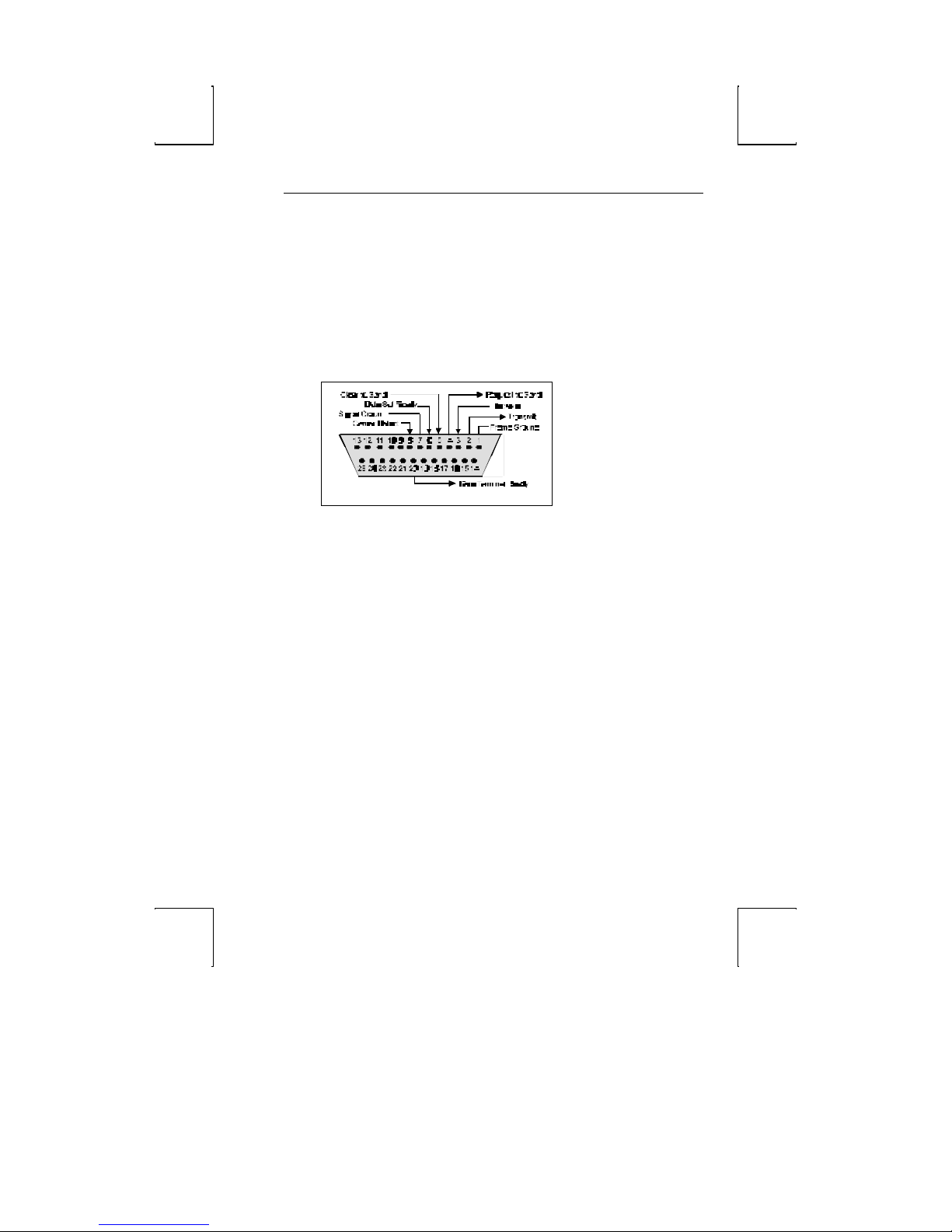
Host Port 1
This port, labeled “SES1-EIA,” is designed for connection to the host (computer or
modem) via a 25-pin D-shell (DB25) female connector. This port uses an RS-232-C
communication interface, is configured as a DTE (Data Terminal Equipment) device,
and can operate from 110 to 38,400 baud. The pins supported are shown below:
Host Port 1 Pin Assignments
Page 25
10 Introduction
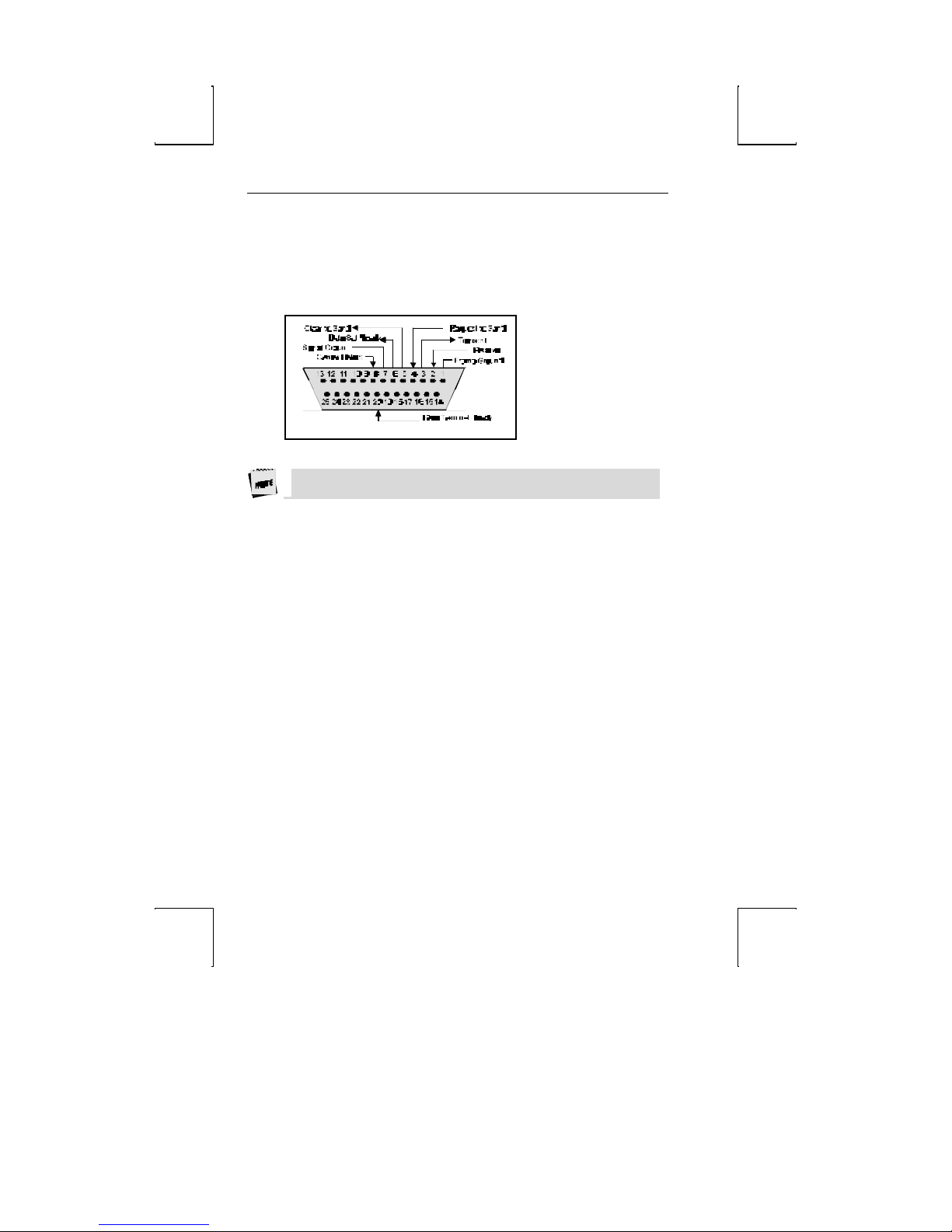
Host/Printer Port 2
This port, labeled “SES2-AUX,” is designed to connect to a host connection
(computer or modem) or a serial printer, and can operate from 110 to 19,200 baud.
This port uses an RS-232-C interface via a DB25 female connector, and is configured
as a DCE (Data Communication Equipment) device. The pin assignments for this
port are shown below:
Host/Printer Port 2 Pin Assignments
Refer to the Installation chapter for details on the connection of all ports to serial
devices (hosts, modems, or printers).
Page 26
Communications 11
SES1 EIA
DTR
pin2
pin3
pin6
SES2 AUX
pin2
pin3
pin6
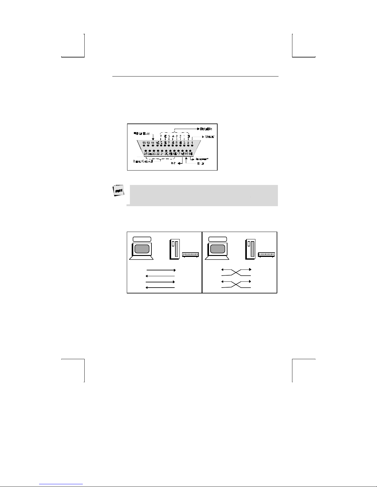
Parallel Printer Port
This port, labeled “PAR,” is designed for connection to a parallel printer, which has a
Centronics interface with a 25-pin D-shell female connector. This port, unlike the
others, is a uni-directional device—it only serves to output data to the printer and
cannot receive data. The pins and signals supported are shown below:
Parallel Port Pin Assignments
* These signals are held high, in an inactive state.
If you have opted to use a parallel printer, but it is not connected, an error message
will appear on the status line when any PRINT operation is done. This error will not
affect your terminal’s operation. Any activity that updates the top status line (such as
pressing the CAPS LOCK key) will clear the error message.
Terminal to Modem (DCE) or Host
Refer to the diagram below to understand why a null modem adapter may be needed
when connecting the second serial port (SES2-AUX) to a modem or a DCE host. The
first serial port will connect directly without a null modem since it is a DTE device.
DTE
Transmit
Receive
DSR
pin2
pin3
pin20
pin6
pin20
Host
D
C
E
Transmit
Receive
DTR
DSR
Modem
DCE
Receive
Transmit
DTR
DSR
pin2
pin3
pin20
pin6
pin20
Host
D
C
E
Modem
Transmit
Receive
DTR
DSR
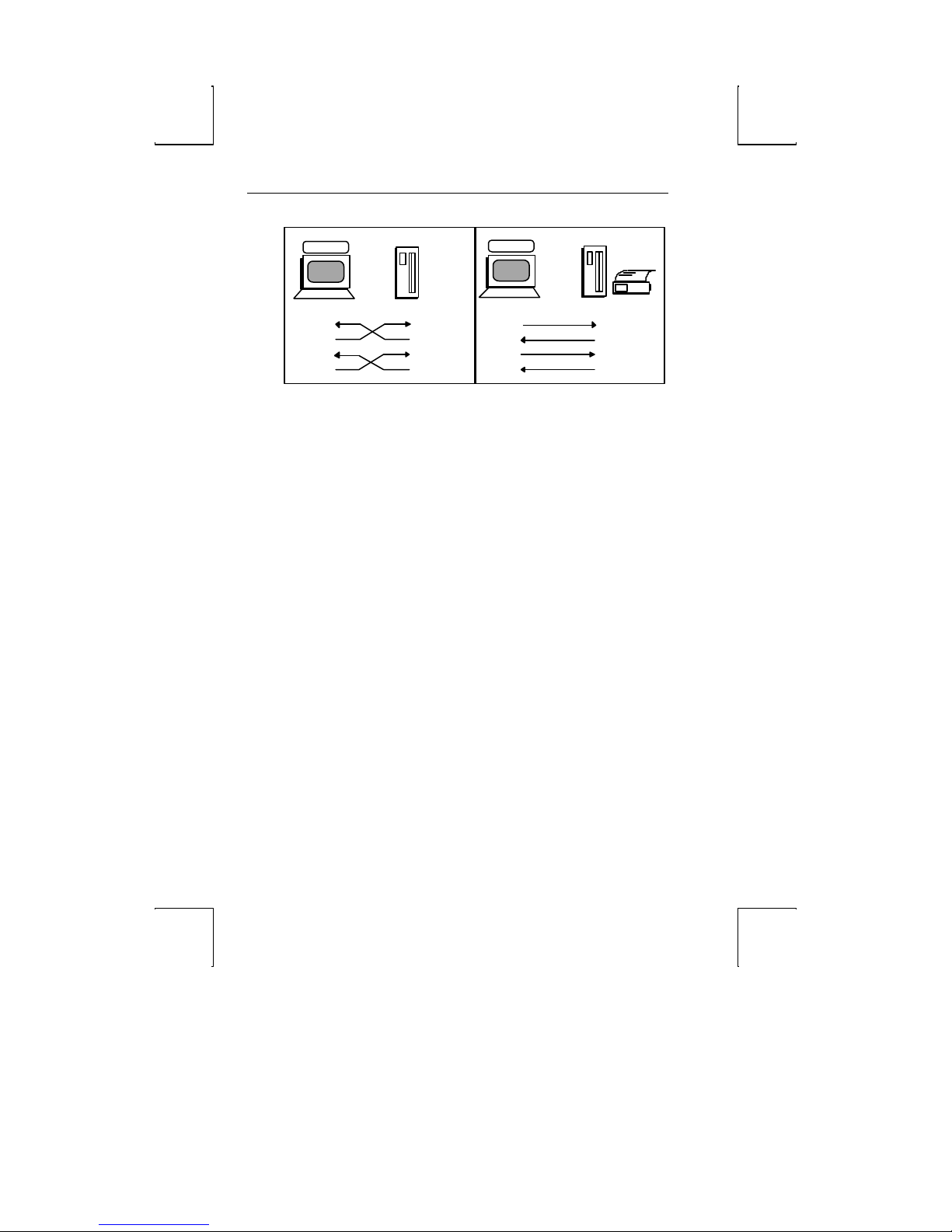
Terminal to Host (DTE) or Printer
Refer to the diagram below to understand why a null modem adapter may be needed
when connecting the first serial port (SES1-EIA) to a host port or a modem. The
second port (AUX) will connect directly, without a null modem, since it is a DCE
device (most serial printers are DTE devices).
Page 27
12 Introduction
pin2
pin3
pin6
D
D
DTR
pin2
pin3
pin6
SES1 EIA
DTE
Transmit
Receive
DSR
pin2
pin3
pin20
pin6
pin20
Host
T
E
Transmit
Receive
DTR
DSR
SES2 AUX
DCE
Receive
Transmit
DTR
DSR
pin2
pin3
pin20
pin6
pin20
Screen Display and Pages
This terminal offers two lengths: 26 and 44 lines. These numbers include the top and
bottom status lines (or label line), as well as the lines used to display data. A “page” of
terminal memory represents the total number of lines that can be accessed, whether or
not they are all viewable on the screen at once.
Bottom Status/Label Line Display
If the “Data Lines” selection is “24/42”, then the bottom status/label line is available.
If the “Data Lines” selection is “25/43”, then the bottom status/label line is not
available.
Host
T
E
Transmit
Receive
DTR
DSR
Serial
Printer
Page 28

chapter
2
Installation
This section provides a “walk-through” approach to the installation of your terminal.
This will enable you to physically connect the terminal to a printer and a host
computer/modem, as well as to configure the Setup menu to suit your requirements
and preferences.
The procedures described here are among the most common. Described here are
conventional setups, with or without a printer. These steps may need to be adjusted to
meet your requirements.
STEP 1 – Know Your Devices
The first step in our installation process will be to determine what type of serial ports
you are connecting to the terminal. The Communications section in the Introduction
chapter describes the differences between a DTE and DCE serial device. Determine
what type of devices you are using (a DTE host, a DCE modem, a DTE printer, a
parallel printer, etc.).
13
Page 29

14 Installation
STEP 2 – Physical Connections
Depending on the types of serial interfaces of your devices, you may need one or more
“null modem” adapters to communicate properly.
First, refer to the Common Setups diagrams later in this chapter. If one of these setups
matches your needs, make the connections as shown in the diagrams by referring to
the Host/Printer Connection Guide shown later in this chapter. Each cable
connection in the diagram (the lines with arrows on each end) has a letter next to it.
The letters correspond to the letters in the Host/Printer Connection Guide. If these
setups don’t apply, choose the connections in the Host/Printer Connection Guide
that are appropriate.
Your physical connections are now complete.
STEP 3 – No Printer Option
If you did not opt to install a printer (do not complete connection E, F, or G), you
must set the “Printer Use” selection in the GLOBAL Setup menu to “None”.
STEP 4 – Know Your Serial Port(s) Protocol
Consult your system administrator to find out the communication settings on all the
serial devices you are connected to, including EIA (or Aux) baud, data bits, stop bits,
parity, parity checking on/off, and flow control protocol. This could include a
host/modem, or a serial printer.
Page 30

STEP 5 – Communications Setup Selections 15
STEP 5 – Communications Setup Selections
To complete this step, you must recall the letters next to the connections that you
made in Step 2.
The procedures below correspond directly to the individual connections made.
Notice that only certain connection procedures are to be followed, not all of them.
For example, if you have made connections “C” and “F” to a modem and a serial
printer, then follow connection procedures “C” and “F” below.
Only follow those steps that apply to your connections (A-G).
To access the Setup menu, press SHIFT-SETUP on an ASCII keyboard or Shift-Print
Scrn on a PC+ keyboard.
Connection A: Host DCE
1. Enter the Setup menu.
2. In the COMM menu, set the proper communications settings for the EIA Baud,
EIA Data Format, EIA Parity Check, EIA Recv, and EIA Xmt selections. See
the Setup chapter for more information on the individual settings.
Connection B: Host DTE
1. Enter the Setup menu.
2. In the AUX/COMM2 menu, select the proper communication settings. See the
Setup chapter for more information on the individual settings.
Page 31

16 Installation
Connection C: RS-232 with Modem
1. Follow all procedures of Connection A.
Connection D: RS-232-C with Modem
1. Follow all procedures of Connection B.
Connection E: RS-232-C Printer
1. In the GLOBAL Setup menu, set the “Printer Use” selection to “SES1/SER”.
2. Follow procedure of Connection B, step 2.
Connections F and G: Parallel Printer
1. Enter the Setup menu.
2. In the GLOBAL Setup menu, set the “Printer Use” selection to either
“SES1/PAR” or “SES2/PAR” for single or dual host environment.
STEP 6 – Emulation Setup Selection
This step requires setting a selection in the Setup menu to configure the emulation of
the “Terminal”. Determine which emulation your applications run with.
Enter the Setup menu. In the MODE menu, set the “Terminal” selection to match
your emulation requirements.
STEP 7 – Additional Setup Options
At this point, you should proceed to the Setup chapter and continue to set up your
own selections for any other parameters such as those for the display, keyboard,
function/edit keys, and tabs.
Page 32

STEP 8 – Save Parameters 17
STEP 8 – Save Parameters
Finally, remember to save your Setup parameters in permanent memory, so that they
can be recovered if the terminal is powered down. When you exit the Setup menu,
the prompt “Save parameters before exit? (Y/N)” appears. To save parameters select
“Y”. Another way to save parameters is to move the highlight bar over the “Save
Parameters” field in the EXECute menu and press the “space” bar.
Remember to save your Setup settings after the entire installation process.
STEP 9 – Establish Communications
Your installation is now complete. By pressing the Return or Enter key, you should be
able to communicate with the host computer(s).
If for some reason, your installation was not successful, make sure your physical
connections are secure, that the communications protocol settings match your
devices, and that the Setup selections are chosen to provide a proper interface between
the terminal and your devices.
If you continue to have problems installing the terminal, call your local dealer for
technical support.
Page 33
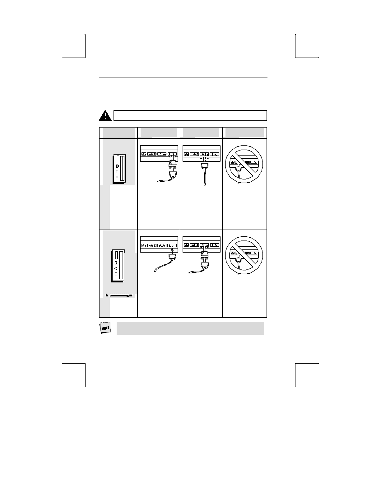
18 Installation
Host/Printer Connection Guide
CAUTION: Do not (un)plug in electrical storm.
DTE Host*
SES1-EIA (DTE) SES2-AUX (DCE) PAR
Connection A:
Connect a null
modem adapter
between the host
Connection B:
Connect the host
cable directly to
the AUX port.
Not applicable.
cable and the EIA
port.
DCE Host
or Modem
Connection C:
Connect the host
or modem cable
directly to the EIA
port.
Connection D:
Connect a null
modem adapter
between the host
or modem cable
and the AUX port.
Not applicable.
*Most host computers are configured as a DCE device. The Mentor® System is an
example of a DCE host system.
Page 34
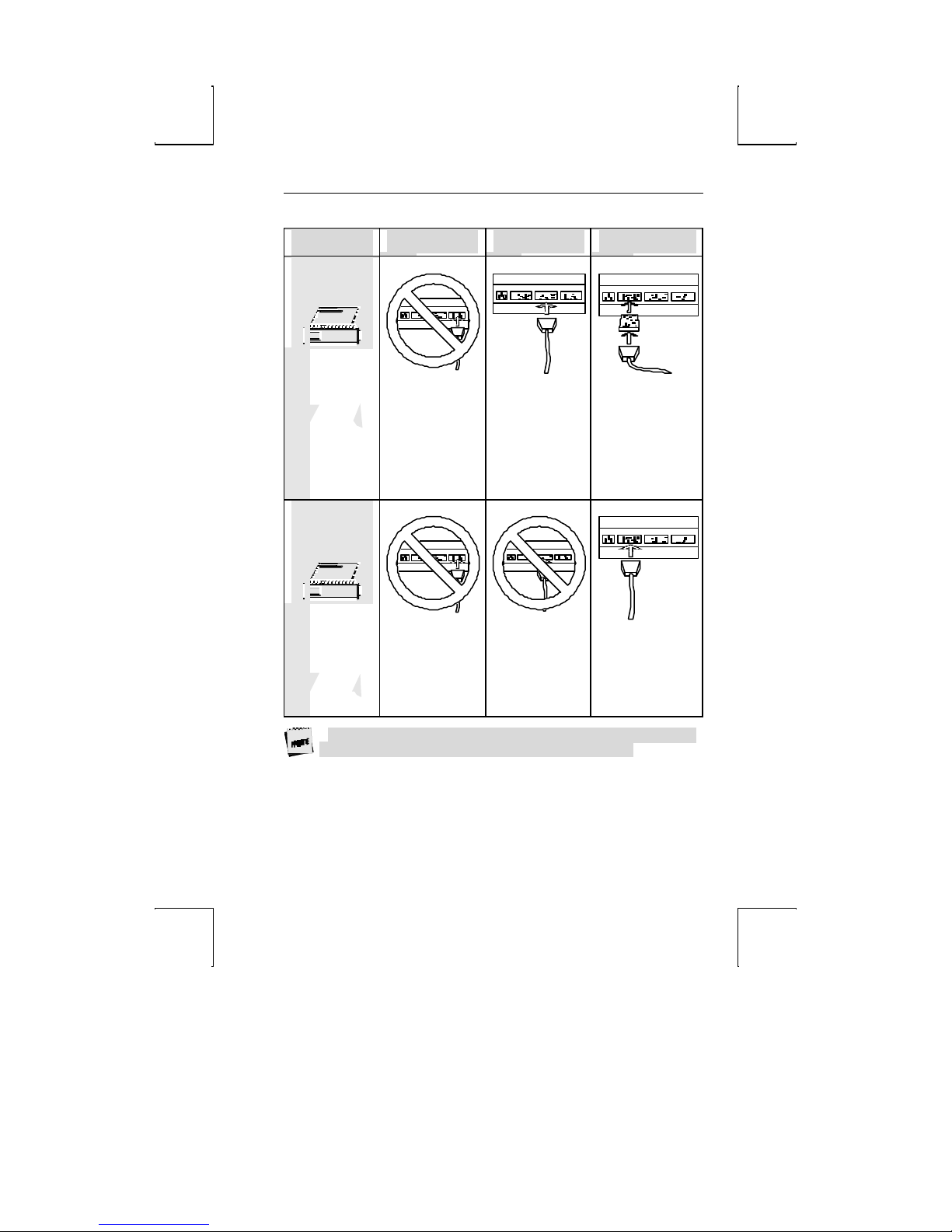
Host/Printer Connection Guide 19
DTE Serial
Printer**
SES1-EIA (DTE) SES2-AUX (DCE) PAR
Not applicable.
Parallel Printer
(Centronics/
IBM)
Not applicable.
** Most serial printers are configured as DTE devices.
Connection E:
Connect the serial
printer cable
directly to the
AUX port.
Not applicable.
Connection F:
This is an option if
you connect a
parallel-to-serial
converter between
the serial printer
cable and the PAR
port.
Connection G:
Connect the parallel
printer cable to the
PAR port.
Page 35

20 Installation
This page is intentionally left blank.
Page 36
chapter
3
c
Setup
Overview
Your terminal can be configured to operate in a variety of different modes to suit your
needs and to conform with the requirements of your host computer. Operating
parameters can be selected as described in the paragraphs that follow.
Setup Menu
The Setup menu allows you to select the emulation you wish to operate in, program
your function keys, set tab stops and select operating parameters from your keyboard.
These parameters can also be downloaded from the host computer. Easy to read
menus are available to help you select the operating parameters to suit your needs.
To enter the Setup Menu or toggle between host 1 and host 2, you need to invoke the
following keystrokes, depending upon the type of keyboard being used. (See below.)
Keyboard Type Setup Menu Toggling Host
ASCII SHIFT-SETUP CTRL-SETUP
PC/+ Shift-SysRq Ctrl-SysRq
21
Page 37

22 Setup
The names of the menus will be displayed on the top status line as follows:
EXEC1 GLOBAL COMM1 AUX/COMM2 KEYBOARD1 SCREEN1 VISUAL1 MODE1 TAB1 FUNCT1 BELL
The currently displayed menu is identified by highlighting its name on the top status
line. ENTER and SHIFT-ENTER are used to move back and forth respectively through
the menus. Moving from one menu selection to another can also be accomplished by
pressing the first letter of the selection itself (e.g. "B" to get to the BELL menu or "M"
to get to the MODE menu).
All but two Setup menu names have a number appended to them (1 or 2). This
number represents which host port parameters are being shown. For example,
EXEC1 or SCREEN1 are showing setup parameters for host port 1. Those menu
names with no numbers appended represent global parameters common to both
host ports
Cursor Keystrokes for Movement Within the Setup Menu
↑ or ↓ – Used to move the cursor up and down within a menu.
←, → or Space Bar – Used to select the parameter value or to perform the function
selected in the menu.
Menus have two types of fields. They are action fields and multiple choice fields.
1. An action field only has a single entry and is executed by pressing the Space Bar.
2. A multiple choice field has more than one option. The selected option is
displayed in bold. To change parameters in a multiple choice field, press ← or
→ or the Space Bar until your choice is displayed.
To save changed parameter values in non-volatile memory, select Save in the EXEC
menu, or press "Y" at the prompt "SAVE PARAMETERS BEFORE EXIT ? (Y or
N). Selecting "Y" at this field saves parameter values for both sessions.
Look at the bottom line in any setup menu if you forget these movement
keystrokes.
The following pages will display what will appear on your screen
as each menu is chosen, and a definition of the possible
parameters.
Page 38
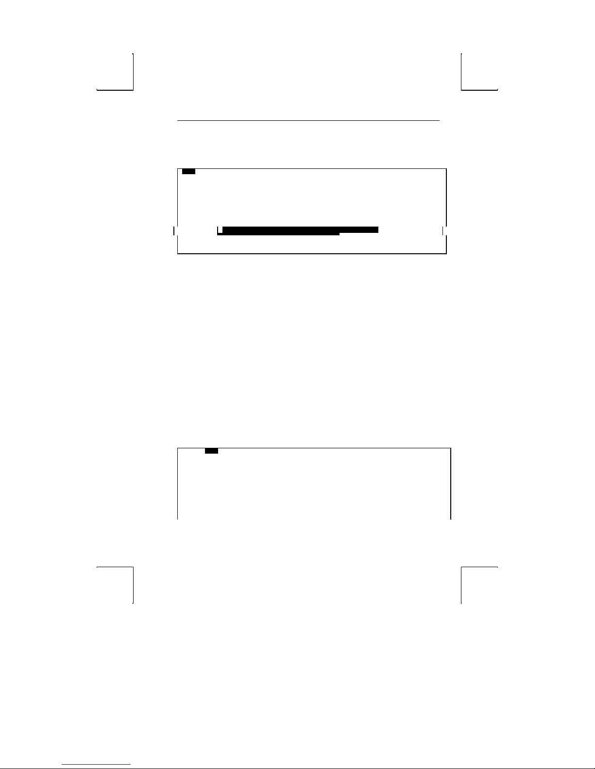
FUNCT1
EXECute Menu 23
EXECute Menu
EXEC1 GLOBAL COMM 1 AUX/COMM 2 KEYBOARD1 SCREEN1 VISUAL1 MODE1 TAB1
Exit
Save Parameters
Load Default Parameters
Load Default Programmable Keys
Clear Screen
Clear Communication
SAVE PARAMETERS BEFORE EXIT? (Y or N)
ENTER:menu ↑ ↓ :line ← → SPACE:select S-SETUP:exit CTL-SETUP:SES#1
When you first enter the Setup Mode, the EXECute menu will be highlighted. All
selections in this menu are action fields and are invoked by pressing the Space Bar.
Exit - Exits Setup Mode and returns user to display screen.
Save Parameters - Stores the current parameter values of the Setup Mode menus in
non-volatile memory. To save parameters return to Execute menu selection and use
the cursor arrow keys to highlight the Save Parameters field. Press the Space Bar
once to execute Save, and press the Space Bar again to exit the Setup mode.
When editing host 1 parameters, Save Parameters will only save the host 1 parameters.
To save parameters for host 2 you must first toggle to host 2 (CTRL-SETUP on ASCII
keyboard or Ctrl-Sys Req on PC+ ke yboard), then select Save Parameters.
Save Parameters Before Exit? (Y or N) - Select Y to save all parameters in both
sessions. Select N to exit without saving parameters. This selection serves as a
reminder to Save changed parameters before exiting Setup.
Load Default Parameters - Loads original factory settings into memory, regardless of
the emulation selected.
Load Default Programmable Keys - Loads factory settings for programmable type
keys into memory. These settings will be dependent on the emulation selected.
Clear Screen - Clears the application screen.
Clear Communication - Enables you to empty the receive and transmit buffers of the
terminal.
BELL
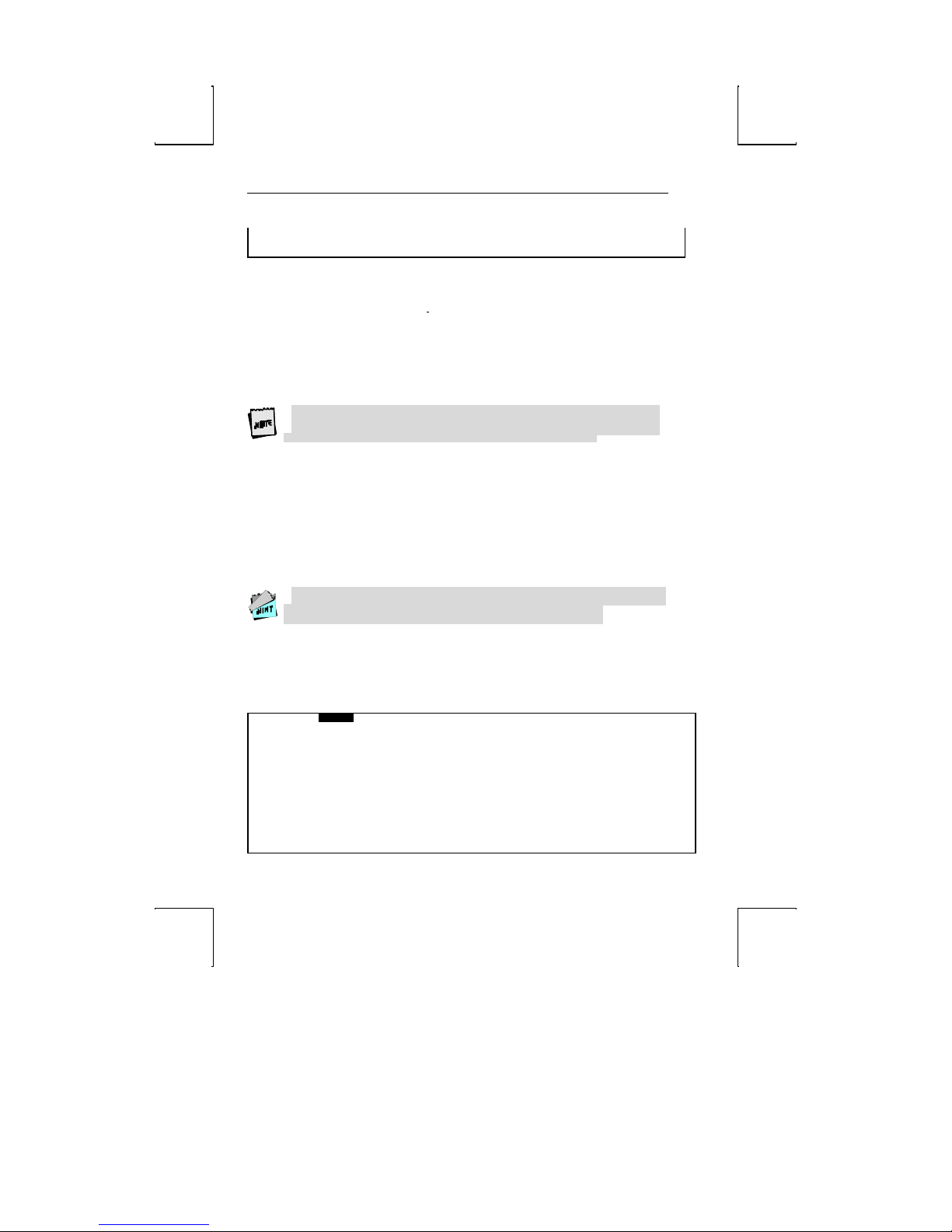
GLOBAL Menu
EXEC1 GLOBAL COMM1 AUX/COMM2 KEYBOARD1
Screen Timeout Yes No
Fore/Back Blk/Wht Wht/Blk Blk/Hlfint Hlfint/Blk
Scroll SM 8 SM 4 SM 2 SM 1 Jump
Lines/Sessions 26/1 26/2 44/1 44/Split
Printer Use SES1/SER SES1/PAR SES2/PAR None
Overscan Border Yes No
Refresh Rate 60Hz 71Hz 82Hz 100Hz
VISUAL1 MODE1 TAB1 FUNCT1 BELL
Page 39
24 Setup
FUNCT1
ENTER:menu ↑ ↓ :line ← → SPACE:select S-SETUP:exit CTL-SETUP:SES#1
Screen Timeout [Yes No]
Causes the screen to dim after 15 minutes of inactivity until the first character is
received from the host computer or keyboard. While the screen is dim, the LOCK key
LED will flash on and off. CTRL or SHIFT will reactivate the display without
disturbing the displayed data.
Fore/Back [Blk/Wht, Wht/Blk, Blk/Hlfint, Hlfint/Blk]
Choose to display foreground (Fore) and background (Back) as black/white,
white/black, black/half intensity, or half intensity/black.
Scroll [SM 8, SM 4, SM 2, SM 1, Jump]
Select your screen to jump or smooth scroll. Four rates of smooth scroll are available,
SM1 representing the slowest, SM8 representing the fastest.
In 44/split mode with smooth scroll enabled, the terminal will default to jump
scroll.
Lines/Sessions [26/1, 26/2, 44/1, 44/Split]
Select the total number of lines displayed and the session to be enabled. The number
of data lines in the scrolling region is selected in the SCREEN menu. Entering or
exiting 44/1 will erase the screen(s). For information on dual session operation refer
to Section 6: Multi host/Split Screen.
Printer Use [SES1/SER, SES1/PAR, SES2/PAR, None]
Select session 1 serial or parallel printer, session 2 parallel, or no printer. If dual host is
selected SES1/SER is not available. If single host is selected, SES2/PAR is not
available.
Overscan Borders [Yes, No] choose whether the overscan borders are active. The
borders extend video from one edge of the screen to the next.
To see the borders, select Blk/Wht or Blk/Hlfint in the Fore/Back parameter.
Refresh Rate [60 Hz, 71 Hz, 82 Hz, 100 Hz] select the rate (number of times per
second) at which the image on your terminal’s display is updated. This selection is
only applicable to 26 line display mode.
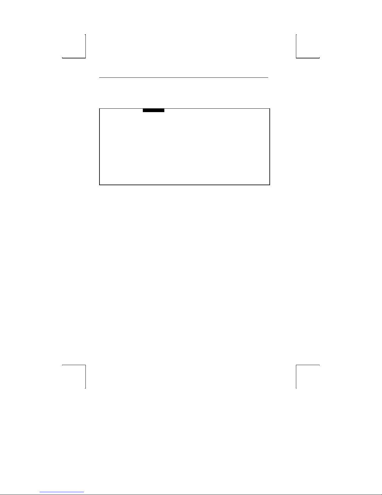
COMMunications Menu (Sess 1 - EIA)
EXEC1 GLOBAL COMM1 AUX/COMM2 KEYBOARD1 SCREEN1 VISUAL1 MODE1 TAB1
Mode Block H-Blk FDX/Line HDX/Echo
Baud Rate 38400 19200 9600 4800 2400 2000 1800
1200 600 300 150 110
Parity None Odd Even
Parity Check Yes No
Data Bits 7 8
Stop Bits 1 2
Xon/Xoff None DTR DC1/DC3 Both
Pace 00
Terminator US/CR CRLF/ETX
XPC Off On
BELL
Page 40

COMMunications Menu (Sess 1 - EIA) 25
ENTER:menu ↑ ↓ :line ← → SPACE:select S-SETUP:exit CTL-SETUP:SES#1
Mode [Block, H-Blk, FDX/Line, HDX/Echo]
Four selections are available for defining communication protocol.
Baud Rate [38400, 19200, 9600, 4800, 2400, 2000, 1800]
Various baud rates are availabl e to match the data rate for your computer system.
Parity [None, Odd, Even]
Multiple selections are available to meet the requirements of your host computer.
Parity Check [Yes, No]
When Yes is selected, an asterisk (*) symbol will be displayed on your screen at any
character position where an error in parity is detected by the terminal on incoming
data.
Data Bits [7, 8]
Select 7 or 8 bit character operation.
Stop Bits [1, 2]
Select to append 1 or 2 stop bits at the end of a character.
Xon/Xoff [None, DTR, DC1/DC3, Both]
Select DTR, DC1/DC3 or both for data flow control. Flow control must be used
when using smooth scroll.
Pace [00]
Relative amount of delay time between characters during transmission to host (00-99).
Use right arrow to increase value and left arrow to decrease value.
When transmitting large character strings of function key data, this feature will be
useful in preventing any characters from being lost during transmission to the host.
Terminator [US/CR, CRLF/ETX]
This field sets the end of line/end of page characters for block mode.
XPC [Off, On]
Set data flow control for PC Term Operation. This option modifies the Xon/Xoff
characters.
Page 41
26 Setup
AUXiliary/COMMunications Menu (Sess 2 - AUX)
EXEC1 GLOBAL COMM1 AUX/COMM2 KEYBOARD1 SCREEN1 VISUAL1 MODE1 TAB1 FUNCT1 BELL
Mode Block H-Blk FDX/Line HDX/Echo
Baud Rate 19200 9600 4800 2400 2000 1800
1200 600 300 150 134.5 110
Parity Odd Odd Even Space Mark
Parity Check Yes No
Data/Stop Bits 7/1 8/1 7/2 8/2
Xon/Xoff None DTR DC1/DC3 Both
Aux Echo Yes No
Pace 00
Terminator US/CR CRLF/ETX
XPC Off On
ENTER:menu ↑ ↓ :line ← → SPACE:select S-SETUP:exit CTL-SETUP:SES#1
Mode [Block, H-Blk, FDX/Line, HDX/Echo]
Four selections are available for defining communication protocol.
Baud Rate [19200, 9600, 4800, 2400, 2000, 1800]
A wide range of baud rates are available to match the data rate for your printer/host.
Parity [Odd, Even, Space, Mark]
Four selections are available to meet the requirements of your printer/host.
Parity Check [Yes, No]
When Yes is selected, an asterisk (*) symbol will be displayed on your screen at any
character position where an error in parity is detected by the terminal on incoming
data.
Data/Stop Bits [7/1, 8/1, 7/2, 8/2]
Select 7 or 8 bit character operation with either 1 or 2 stop bits appended at the end of
a character.
Xon/Xoff [None, DTR, DC1/DC3, Both]
Select DTR, DC1/DC3 or both for data flow control for received character text. Flow
control must be used when using smooth scroll.
Page 42

AUXiliary/COMMunications Menu (Sess 2 - AUX) 27
Aux Echo [Yes, No]
When Yes is selected in this field, data received from the serial auxiliary device will be
displayed on the terminal screen. (This is only available in single host mode.)
Pace [00]
Enables user to preset a delay between characters during transmission. Select from
values of 0 to 99. Use right arrow to increase value and left arrow to decrease value.
This is useful if characters are lost when pressing function keys.
Terminator [US/CR, CRLF/ETX]
This field sets the end of line/end of page characters for block mode.
XPC [Off, On]
Sets data flow control for PC Term Operation. This option modifies the Xon/Xoff
characters.
Page 43
28 Setup
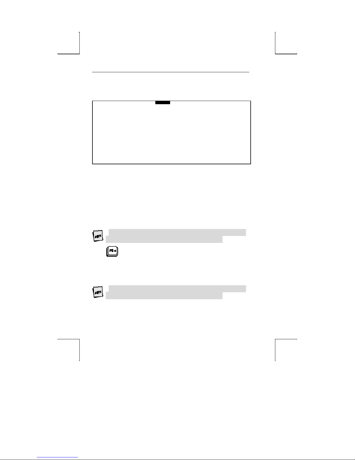
KEYBOARD Menu
EXEC1
Case Select Upper/Upper Upper/Lower Lower/Upper Lower/Lower
Space Char Destructive Non Destructive
Keyclick Yes No
Keyboard US UK French Spanish
German Swedish Danish Norwegian
Portuguese Dutch Belgian Italian
Latin Amer Fr Canadian Sw German Sw French
Print Scrn Key Print Page Aux On/Off
Break Key Break Ctrl Break
Nat’l Replace Yes No
Ext’d Char Set Yes No
ENTER:menu ↑ ↓ :line ← → SPACE: select S-SETUP:exit CTL-SETUP:SES#1
COMM1 AUX/COMM2 KEYBOARD1 SCREEN1 VISUAL1 MODE1 TAB1 FUNCT1 BELL
Case Select [Upper/Upper, Upper/Lower, Lower/Upper, Lower/Lower]
Select to display characters as all upper case, upper shift to lower case, shift lower case
or all lower case.
Space Char [Destructive, Non Destructive]
Determines whether or not the Space Bar will over write (destructive) or pass over
(non-destructive) data on the screen.
Keyclick [Yes, No]
Choose to have an audible tone sound each time a key is pressed on the keyboard. The
volume of this tone may be adjusted in the BELL menu.
Keyboard [U.S., UK, French, Spanish, German, Swedish, Danish, Norwegian,
Portuguese, Dutch, Belgian, Italian, Latin Amer,
Fr Canadian, Sw German, Sw French]
For selection of appropriate languages.
The same language should be selected for both sessions.
Print Scrn Key [Print Page, Aux On/Off]
Selecting Print Page transmits a page of data when this ke y is pressed. Selecting Aux
On/Off transforms the Print Scrn Key into a toggle between Aux-on and -off.
Print Send Key [Print Page, Aux On/Off]
Selecting Print Page transmits a page of data when this key is pressed. Selecting Aux
On/Off transforms the Print Send Key into a toggle between Aux-on and-off.
Aux On/Off is only available in ASCII emulations.
Break Key [Break, Ctrl Break]
Choose if the Break key alone or Ctrl-Break generates a break.
Nat’l Replace [Yes, No]
Choose between the US ASCII chart for characters 0-127 or the NRC set that matches
Page 44

KEYBOARD Menu 29
your keyboard language. As a default (yes) it will match the keyboard’s language, but
it can be disabled to retain the US set.
Ext’d Char Set [Yes, No]
Choose whether to permit access to the characters loaded in 128-255. The extended
character set that is accessed depends on the language selected, and requires 8-bit data.
Three extended character sets are available:
1. Standard PC– used only when keyboard language is US or UK.
2. Multilingual – used when any language other than US, UK, or Portuguese is
selected.
3. Portuguese – this is a variation of the Multilingual set and is used only when the
language is Portuguese.
You may elect to use the extended character set, but you can not directly specify
which of the three character sets will be used. The terminal will select the set based
on the selected Keyboard language.
Page 45

30 Setup
SCREEN Menu
EXEC1 GLOBAL COMM 1 AUX/COMM2 KEYBOARD1 SCREEN1 VISUAL1 MODE1
Auto Wrap Yes No
Auto Scroll Yes No
Auto Line Feed Yes No
Margin Bell Yes No
Column Change Save Screen Erase Screen
Columns 80 132
Cursor Home Upper left Auto Scroll Dependent
Data Lines 24/42 25/43
ENTER:menu ↑ ↓ :line ← → SPACE: select S-SETUP:exit CTL-SETUP:SES#1
Auto Wrap [Yes, No]
Selecting Yes will cause the cursor to wrap to the beginning of the next line when it
passes the right margin. A No selection will cause the cursor to remain stationary at the
right margin.
Auto Scroll [Yes, No]
Selecting Yes will cause the screen to scroll up when data is entered passed the margin
of row 24/42 (25/43) depending on data line setting. A No selection will cause the
cursor to position itself at the first position of row 1, when data is entered at the last
position on row 24/42 (25/43).
Auto Linefeed [Yes, No]
If Yes is selected, an internal linefeed is performed moving the cursor to the beginning
of the next row when a Return code is received. An internal linefeed is also generated
when the cursor advances past the end of a row. Selecting No will cause the cursor to
move to the beginning of the current row when a Return code is received.
Margin Bell [Yes, No]
Sounds a momentary audible sound when the cursor is nearing the end of the right
margin. Selecting No will disable this feature.
Column Change [Save Screen , Erase Screen]
Select to save screen data or erase screen data when changing number of columns (80 or
132) display.
Columns [80, 132]
Select to display 80 or 132 columns.
FUNCT1 BELL
Page 46
VISUAL Menu 31
TAB1
Cursor Home [Upper Left, Auto Scroll Dependent]
Select to position the cursor at the Upper left hand corner of the display screen, or
Auto-Scroll Dependent. With Auto Scroll disabled (see Auto Scroll above), selecting
Auto Scroll Dependent positions the cursor at the Bottom Left hand corner of the
display screen when a Cursor Home command is received.
Data Lines [24/42, 25/43]
Selecting 24/42 allows you 24 or 42 data lines with a top and bottom status line.
Selecting 25/43 allows for 25 or 43 data lines with only a top status line. This
selection is dependent on the session selected in the GLOBAL menu.
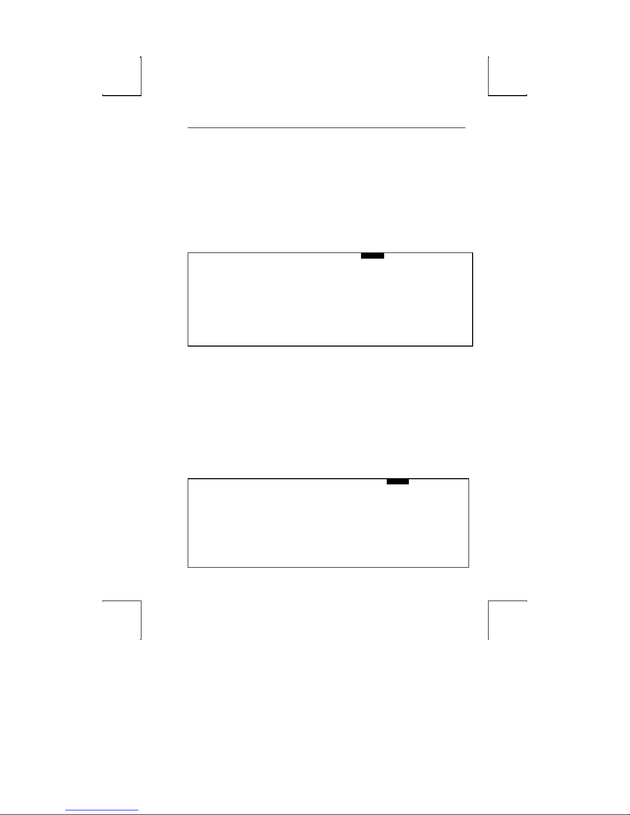
VISUAL Menu
EXEC1 GLOBAL . COMM1 AUX/COMM2 KEYBOARD1 SCREEN1 VISUAL1 MODE1 TAB1 FUNCT1 BELL
Cursor Block Underline None
Cursor Blink Yes No
Prot Reverse Off On
Prot Half Off On
Prot Blink Off On
Prot Underline Off On
Prot Suppress Off On
Status Line On Off
ENTER:menu ↑ ↓ :line ← → SPACE:select S-SETUP:exit CTL-SETUP:SES#1
Cursor [Block, Underline, None]
Choose to display cursor as a Block, Underline, or None.
Cursor Blink [Yes, No]
Select a blinking display of the cursor with Yes, a steady display with No.
Protected Fields [Off, On]
The next 5 selections select the display characteristics of Protected Fields. They can be
set to display in logical combinations of Reverse, Half Intensity, Blink, Underline, or
Suppressed.
Status Line [On, Off]
Selecting On will display a status line on the top row of your screen. This status line
may be used to display information such as modes of duplex, day, date, time, etc.
Selecting Off will disable this feature.
MODE Menu
EXEC1 GLOBAL COMM1 AUX/COMM2 KEYBOARD1 SCREEN1 VISUAL1 MODE1
Terminal Viewpoint Regent 40 Wyse 50
TVI 925 TVI 920 TVI 910
Haz 1500 VT52 Wyse 75
VT100 PC-Term
Mode Normal Enhanced
Program Keys Terminal Dependent User Dependent
Kybd(s) to use: PC+ or ASCII
ENTER:menu ↑ ↓ :line ← → SPACE:select S-SETUP:exit CTL-SETUP:SES#1
FUNCT1 BELL
Page 47
32 Setup
PC TERM is only displayed as a terminal selection when the PC+ keyboard is
connected.
Terminal [Viewpoint, Regent 40, Wyse 50, TVI 925, TVI 920, TVI 910, Hazeltine
1500, VT52, Wyse 75, VT100, PC -Term
Select the mode compatible to suit your system requirements.
Mode [Normal, Enhanced]
Selecting Enhanced allows the additional features of the terminal to be accessed.
Selecting Normal provides the standard feature set of the terminal selected.
Program Keys [Terminal Dependent, User Dependent]
When changing compatibility modes, selecting Terminal Dependent will set default
codes for all programmable function keys according to the emulation selected.
Selecting User Dependent will allow you to retain codes as programmed and will not
default to codes of the emulation selected.
At power up, default function keys will always be loaded unless User Dependent is
selected at this field.
Keyboards to Use [PC+ or ASCII]
This field highlights the keyboard supported for the emulation selected. No action
may be taken at this field.
If any keys have been programmed, changing terminal modes while Terminal
Dependent is selected will cause that. programming to be lost.
TAB Menu
EXEC1 GLOBAL COMM1 AUX/COMM2 KEYBOARD1 SCREEN1 VISUAL1 MODE1 TAB1 FUNCT1 BELL
10 20 30 40 50 60 70 80
+ ........ + ........... + ........... + ........... + ........... + ........... + ........... + ............ +
Space - clears tab
T - sets tab
C - clears all tabs
ENTER:menu ↑ ↓ :line ← → SPACE:select S-SETUP:exit CTL-SETUP:SES#1
Use the ← and → arrows to select a column position. The display will scroll to allow
you to access any column up to 132.
Space - Pressing the Space Bar clears the tab settings.
T - Sets a tab.
C - Clears all tab settings.
Page 48
FUNCTion Key Menu 33
FUNCTion Key Menu
EXEC1 GLOBAL COMM1 AUX/COMM2 KEYBOARD1 SCREEN1 VISUAL1 MODE1 TAB1 FUNCT1 BELL
Bytes Remaining xxx Key F01 Link Key None Y EIA
N AUX
N LOCAL
Label:
Text:
1
ENTER:menu ↑ ↓ :line ← → SPACE:select S-SETUP:exit CTL-SETUP:SES#1
This menu allows you to program the function keys as well as all other programmable
keys.
Using This Menu
Use the cursor keys to move from field to field on the screen.
Bytes Remaining
Watch the bytes remaining field to see how many characters are left for programming.
Key F01
Selecting a key to be programmed is made by pressing the FUNCT key followed by the
key to be programmed.
Use the left Alt key on the PC/+ keyboard.
The FUNCT followed by a function or an edit key, will update the current key being
modified and display corresponding data for the key requested.
Link Key: None programmed
By linking keys you may cause more than one key to be executed with a single key
stroke. For example, by linking F16 to Fl, when you press Fl, both Fl and F16 are
transmitted. Select N at this field for no link.
If you link Fl to itself, a continuous loop will occur. Pressing
CTRL-TAB will stop the loop.
Linking is accomplished by moving the cursor to the link key field and pressing
FUNCT followed by the key to be linked.
Use the left Alt key on the PC/+ keyboard.
Key Destination: EIA [Y/N]; AUX [Y/N]; LOCAL [Y/N]:
The fields labeled EIA, AUX, and LOCAL set the destination for the transmitted text.
Entering Y enables the destination. N disables it. If destination is N (EIA), N (AUX),
N (LOCAL), text will act like keystrokes (duplex dependent). In full duplex, text
will be sent to the host only. In block mode, text will go to the screen only. In half
duplex environments, text will go the screen and to the host.
Page 49

34 Setup
LABEL
The LABEL field is used to identify the 16/32 general purpose function keys.
The LABEL field is displayed on the 26th screen line during normal operation. The
first 8 labels are displayed on an 80 column screen, and all 16 are shown on a 132
column screen. During normal operation, pressing the SHIFT key will toggle the
display of labels programmed into the unshifted and shifted function keys.
Entering Text
The reverse video area in the middle of the screen is used to enter the key text. The
cursor keys as well as the INS/REPL key can be used to edit the text. The SHIFT key or
CAPS LOCK must be pressed when entering uppercase characters.
Use the cursor keys as well as the Insert and Delete keys on the PC/+ keyboard
to edit the text.
Page 50
BELL Menu 35
SCREEN1
To program function keys through the Setup Menu, you should press the FUNCT key
and the function key to be programmed. You should notice the function key
representation change to the representation for the key to be programmed.
Use left Alt key for the PC+ keyboard.
Function Keys Representation
ASCII PC/+ Normal Shift
FUNCT+ Alt+ F01 f01
FUNCT+ Alt+ F02 f02
FUNCT+ Alt+ F03 f03
FUNCT+ Alt+ F04 f04
FUNCT+ Alt+ F05 f05
FUNCT+ Alt+ F06 f06
FUNCT+ Alt+ F07 f07
FUNCT+ Alt+ F08 f08
FUNCT+ Alt+ F09 f09
FUNCT+ Alt+ F10 f10
FUNCT+ Alt+ F11 f11
FUNCT+ Alt+ F12 f12
FUNCT+ Alt+ F13 f13
FUNCT+ Alt+ F14 f14
FUNCT+ Alt+ F15 f15
FUNCT+ Alt+ F16 f16
BELL Menu
EXEC1 GLOBAL COMM1 AUX/COMM2 KEYBOARD1
0 1 2 3 4 5 6 7 8
Volume ----------------------------------------→
S - Sound Alarm
VISUAL1 MODE1 TAB1 FUNCT1 BELL
Page 51

36 Setup
ENTER:menu ↑ ↓ :line ← → SPACE:select S-SETUP:exit CTL-SETUP:SES#1
The bell volume may be adjusted to a comfortable level by using
← and →. Pressing S will ring the bell so you can experiment to
find the best volume for your environment.
Page 52
chapter
4
Desk Accessories
Clock
Pressing CTRL-F1 will display a clock overlay on your video screen.
Date 1, 1995
Time Set 12:00 AM
Display Off
Type 12
Column 48
Alarm Set 12:00 PM
Tone Alarm/Hourly
Pressing the SHIFT key and ↑, ↓, ← or → will position the clock display anywhere on
your screen. Do not hold cursor keys down (typamatic) when using Desk Accessories.
Press and release cursor keys for proper movement.
Use the following keys to make changes:
þ Up- or down-arrow keys – to enter the field you desire to change.
þ Left- or right-arrow keys – selects the desired parameter to be changed.
þ Spacebar – move through options available for this field.
þ ENTER (num) – revert to the default setting for the current field.
þ ESC – exit clock and save settings.
Time parameters are lost when power is turned off.
Date – enables you to enter the current date.
Time Set – enter the current time of day.
Display – choice to display Time, Date, or Time and Date on the top of your display
screen. Select Off for no display.
Type – select a 12 or 24 hour clock setting.
Column – select column display from column 48 thru 99.
Jan.
39
Page 53

40 Desk Accessories
Alarm Set – enter the time you wish an alarm to sound.
Tone Off – Selections are as follows:
à Off – No alarm sounded.
à Alarm – Alarm to sound at time set.
à Hourly – Alarm to sound every hour.
à Alarm/Hourly – Alarm to sound every hour and at time set.
Press Space Bar to make your selection at this field. To reset the highlighted field to
the factory setting, press ENTER (num).
Page 54
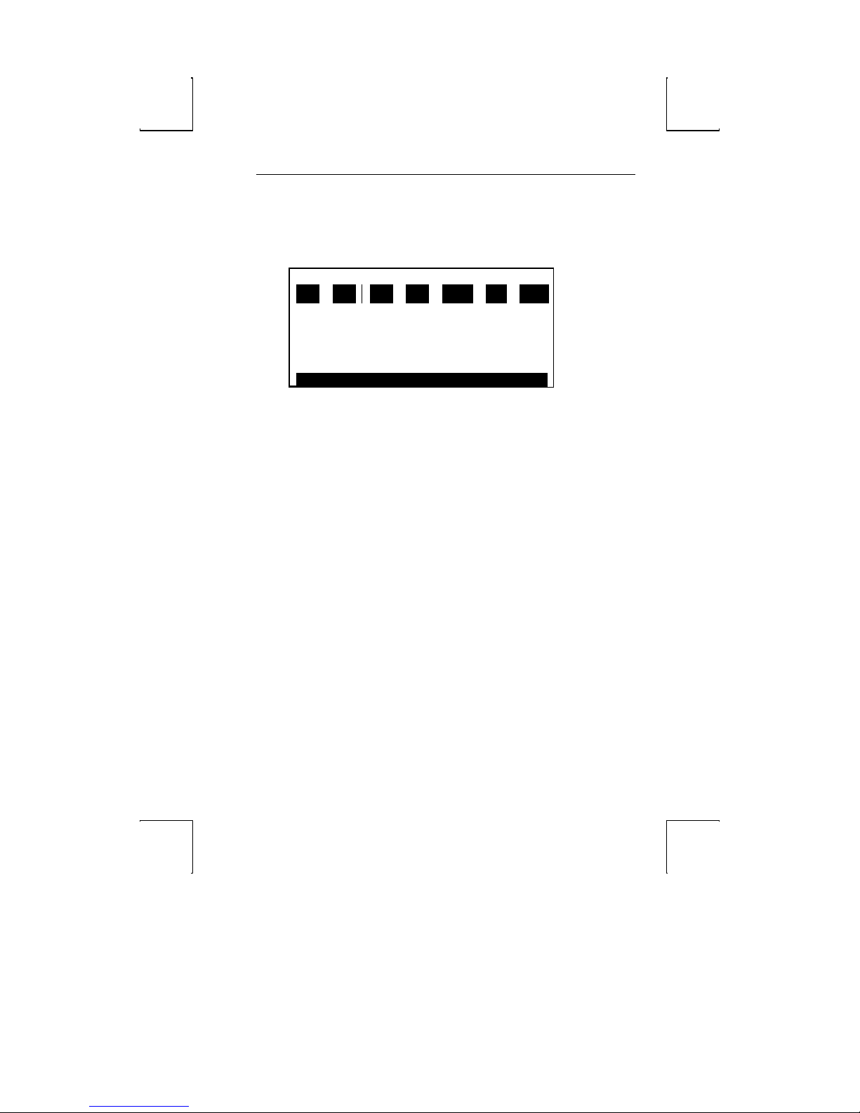
Calendar 41
Calendar
Pressing CTRL-F2 keys simultaneously, will display a calendar overlay on your video
screen. The specified calendar month will display as shown below:
JANUARY 1995
SUN MON TUES WED THUR FRI SAT
1 2
3 4 5 6 7 8 9
10 11 12 13 14 15 16
17 18 19 20 21 22 23
24 25 26 27 28 29 30
31
The keys below control the calendar that is displayed:
þ SHIFT and ↑, ↓, ← or → – will position the calendar display anywhere on
your screen.
þ Right- and left-arrow keys – changes the calendar month.
þ Up- and down-arrow keys – changes the calendar year.
à ENTER – changes Current Date is: to Enter Year: Enter a four digit number from
1600 to 4499. When the fourth number is entered, the new year will
automatically be displayed on your screen. Press HOME to return to current year.
þ ESC – exit calendar and return to normal display screen.
Current Date : Jan. 01, 1995
Page 55
42 Desk Accessories
Calculator (ASCII Keyboard)
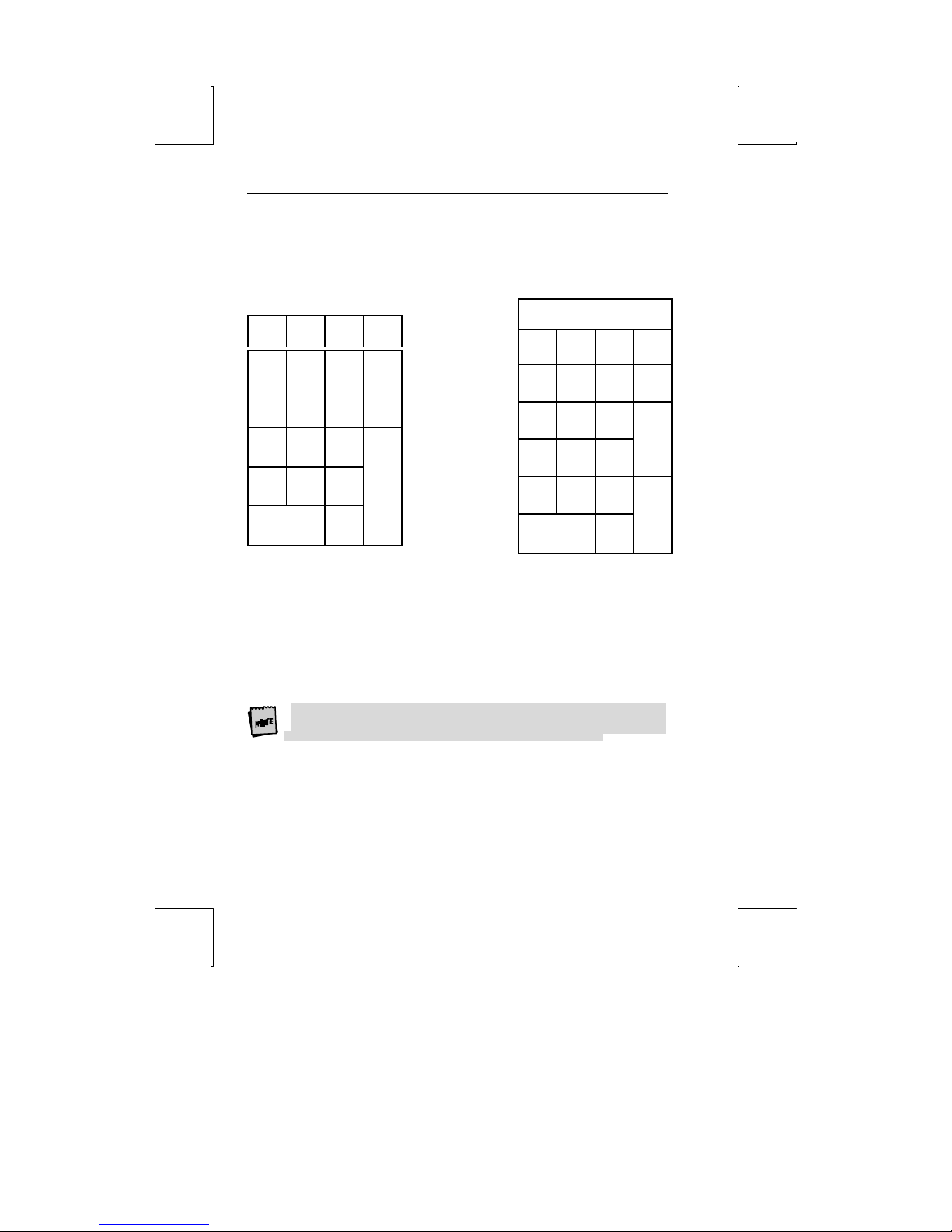
Pressing CTRL-F3 will display a calculator overlay on your display screen.
←←
↓↓
7
4
1
0
ASCII Keyboard
→→
↑↑
8
9
–
5
6
,
2
ENTER
3
.
How To Use:
à CTRL 0-9 – sets # of decimals
à P – for printer on/off
à T – for tape on/off
à X – for transmit result
à SHIFT ←← and →→ – move image
As a key is pressed it is highlighted for a split second. The number pressed will be
displayed on the top row of the calculator image. As you operate the calculator the
answer appears on the top of the calculator image, if tape is enabled.
Printer option on calculator menu must be disabled if a printer is not on-line to the
terminal’s auxiliary port.
0.
M+ M- MR C
% / X –
7
8
4
5
1
2
0
Calculator Display
T
9
+
6
3
.
=
Page 56
Calculator (PC/+ Keyboard) 43
Calculator (PC/+ Keyboard)
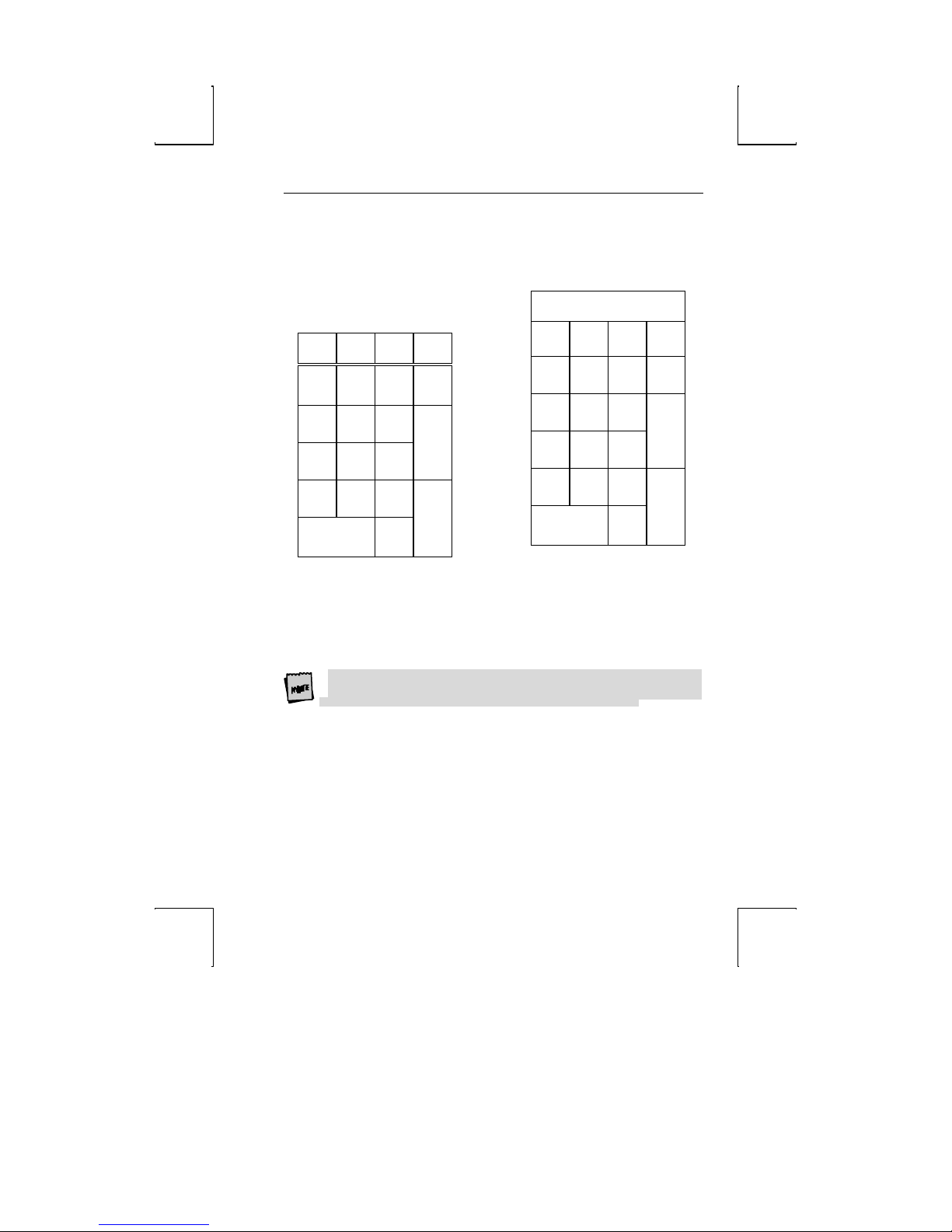
Pressing Ctrl-F3 will display a calculator overlay on your display screen.
How To Use:
à Ctrl 0-9 – sets # of decimals
à P – for printer on/off
Num
Lock
/ , *
7
Home
4
End
0
Ins
8
1
9
Pg Up
5
6
Pg Dn
2
.
Del
3
Enter
+
PC/+ Keyboard
à T – for tape on/off
à X – for transmit result
à Shift ← and → – move image
As a key is pressed it is highlighted for a split second. The number pressed will be
displayed on the top row of the calculator image. As you operate the calculator the
answer appears on the top of the calculator image, if tape is enabled.
Printer option on calculator menu must be disabled if a printer is not on-line to the
terminal’s auxiliary port.
0.
M+ M- MR C
% / X –
7
8
4
5
1
2
0
Calculator Display
T
9
6
3
.
=
+
Page 57

44 Desk Accessories
ASCII Chart
Use the following keys to change the display of the ASCII chart:
à CTRL-F4 – displays an ASCII Chart on your display screen.
à SHIFT and ←,→,↑ or ↓ – postions the ASCII chart anywhere on your screen.
à Up- or down-arrow – scrolls up or down
DEC OCT HEX BINARY CHAR ASCII KEY
254 376 FE 11111110
255 377 FF 11111111
000 000 00 00000000
001 001 01 00000001
002 002 02 00000010
The center line is highlighted and indicates the breakout of the character where the
cursor currently rests. This implementation will save you time in locating a particular
character by simply locating the cursor on the character in question and then activating
the chart. The centered line on the chart represents that particular character.
For example, activating the ASCII Chart after powering up the terminal will result in
SPACE being highlighted as the screen memory initializes to SPACE.
∏∏
″″
NUL
SOH Ctrl-A
STX Ctrl-B
Ctrl-@
Page 58
A
Appendix
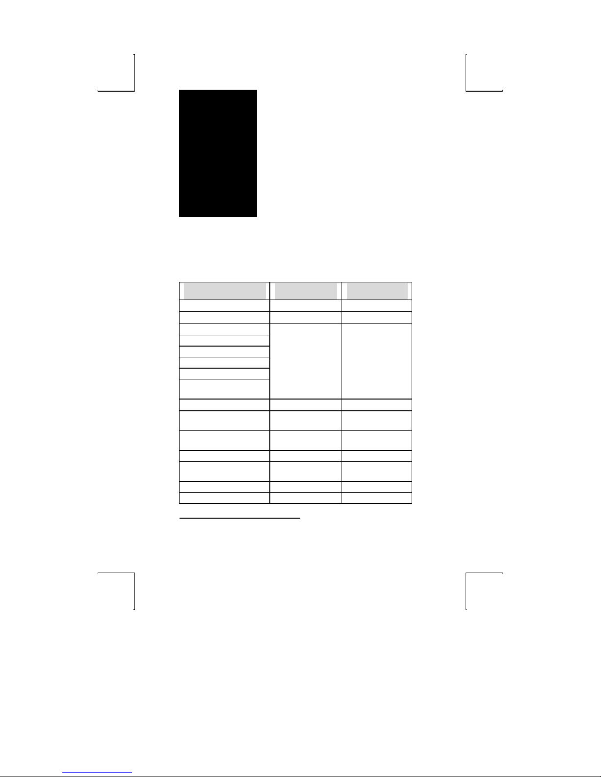
Local Hot Keys
Action
Enter Setup Mode Ctrl-Print Screen SHIFT-SETUP
Exit Setup Mode F1, Space Bar F1, SPACE BAR
Toggle Caps -Lock Lock LOCK
Toggle Num -Lock Num-Lock
Toggle Scroll-Lock Scroll-Lock
Toggle Sessions Ctrl-Print-Screen CTRL-SETUP
Toggle Block-Mode Shift-Pause SHIFT-BREAK
Toggle Monitor Mode1 Ctrl-Shift-1 (num) CTRL-SHIFT-1
Ins/Replace Insert/Shift-Insert INS/REPL
Keyboard Unlock Ctrl-Shift-Print
Hard Reset (Power On) Ctrl-Shift-Home CTRL-SHIFT-
Break2 Ctrl-Pause CTRL-BREAK
Long Break/Disconnect Ctrl-Shift-Pause CTRL-SHIFT-
Function Alt (left side key) FUNCT
Print-Page Print Screen PRINT/SEND
1
Monitor mode is useful when debugging programs; control codes are displayed instead of
executed.
2
The Break signal activates the
PC+Keyboard
Screen
ASCII Keyboard
(num)
SETUP
HOME
BREAK
Continued
45
Page 59
46 Appendix
Continued
Action
PC+ Keyboard
ASCII Keyboard
Increment Scroll Rate Ctrl-Shift-↑ CTRL-SHIFT-↑
Decrement Scroll Rate Ctrl-Shift-↓ CTRL-SHIFT-↓
Change Status Line Ctrl-Shift-→ CTRL-SHIFT-→
Enter Clock Ctrl-F1 CTRL-F1
Enter Calendar Ctrl-F2 CTRL-F2
Enter Calculator Ctrl-F3 CTRL-F3
Enter ASCII Chart Ctrl-F4 CTRL-F4
Enter Diagnostics Ctrl-Shift-F5 CTRL-SHIFT-F6
Exit Any Desk Accessory Esc ESC
Display Code Version
Ctrl-Shift-F5 CTRL-SHIFT-F6
Page 60

NOTE TO INSTALLER
This equipment complies with the FCC Regulation for Class A devices, Subpart J of Part 15.
Shielded, grounded interface cables were used on all ports for FCC radiated emission testing.
The manufacturer is not responsible for any violation of the FCC Regulation for Class A devices
that is caused by unauthorized modification of the equipment, or caused by equipment
installation not in accordance with the instructions in this manual.
This equipment generates, uses, and can radiate radio frequency energy and may cause radio or
television interference. All user equipment that interfaces with other products should be
connected with shielded cables. (Contact a local dealer for more information on shielded cable
assemblies and their availability.)
There is no guarantee that interference will not occur. If radio or television interference occurs
(this can be determined by turning the equipment off and on while the radio or television is on),
the user is solely responsible for correcting the interference and is encouraged to take one or more
of these measures:
1. Reorient the receiving antenna.
2. Relocate the equipment, or move the equipment away from the receiver.
3. Plug the equipment into a different outlet so the unit and receiver are on different
branch circuits.
4. Consult the dealer or an experienced radio/television technician.
It is also suggested that the user read the FCC booklet entitled How to Identify and Resolve
Radio-TV Interference Problems. The booklet is available from the U.S. Government
Printing Office, Washington, D.C. 20402. (When ordering the booklet, specify stock
number 04-000-00345-4.)
Site Preparation
The screen display geometry on terminal products is aligned using magnetic devices. External
magnetic fields created by other types of electronic equipment, such as printers, in very close
proximity to the terminal, may cause minor display distortion.
Examples of display distortion include:
þ Shaky video
þ Wavy lines
þ Tilted display
This magnetic field interaction only occurs over a very short distance, normally less than
twelve inches, and can be corrected by separating the equipment and/or slightly reorienting
the display.
Page 61

Technical Support
Questions about this product should be directed to the Technical Support Department
of the distributor from which you obtained your Boundless Technologies equipment.
When requesting assistance, please have all pertinent information available including
any error messages that may have appeared either on the terminal or the host.
If your distributor fails to provide adequate support for your needs, please contact the
Boundless Technologies Technical Support Department directly. You will be required
to provide the name of your distributor, and a description of the problem as described
above.
Please refer to the Boundless Technologies Guide to Support Services which was
packaged with the terminal.
Boundless Technologies can be reached at:
Boundless Technologies, Inc.
Technical Support Department
50 Engineers Lane, Unit 2
Farmingdale, NY 11735-1208
(800) 231-5445 ext. 1498 (voice)
(631) 962-1505 (fax)
Email: [email protected]
ftp: ftp.boundless.com
Web site: http://www.boundless.com
 Loading...