

Page 1

4000/160
User’s Guide
Page 2

Before using this information and the product it supports, be
sure to read the general information under “Notices.”
It is the policy of Boundless Technologies, Inc. to improve products as new
technology, components, software, and firmware become available.
Boundless Technologies, therefore, reserves the right to change
specifications without prior notice.
All features, functions, and operations described herein may not be
marketed by Boundless Technologies in all parts of the world. In some
instances, photographs are of equipment prototypes. Therefore, before
using this document, consult your Boundless Technologies representative
or Boundless Technologies office for information that is applicable and
current.
Note that Boundless Technologies appreciates receiving suggestions and
comments on its publications. After reading this guide, please comment
and return the comment sheet that has been provided.
Copyright © Boundless Technologies, Inc. 2007.
Farmingdale, New York
Page 3

All rights reserved.
Printed in USA
How to Connect/Disconnect the Terminal iii
Page 4

Page 5

1
This guide...
is a user’s manual and contains all of the information necessary
to install, setup, and use the 160 product.
More detailed information on programming using control codes
and escape sequences, default strings and character sets,
international language support, etc. can be obtained by calling:
USA and Canada calls . . . . 1-800-231-5445
International calls . . . . . . . 1-631-962-1500
At the options menu, press 2 for “Product Information,” then
press 2 for “Products or Program Information Mailed to You,” and
request the following:
260xx Programmer’s Reference Guide
Part Number: 598-0005035
This manual is offered to our customers at no additional charge.
When calling to order, please have your terminal’s serial number
available.
The 160 product’s functionality is a subset of the 260xx
product.
Page 6

Page 7

1
Contents
Preface v
How to Connect/Disconnect the Terminal....................................vi
Notices.............................................................................................vii
Trademarks and Service Marks......................................................vii
Electronic Emission Notices .............................................................ix
Safety Notices.................................................................................xii
Introduction 1
Features............................................................................................2
Compatibility..............................................................................2
Display........................................................................................2
Character Sets...........................................................................2
Communications........................................................................3
Keyboards...................................................................................3
Desk Accessories.......................................................................3
Physical Features ..............................................................................4
Keyboards..........................................................................................5
Usage Notes .......................................................................................7
Communications...............................................................................8
Receive Flow Control.................................................................8
Transmit Flow Control...............................................................9
Host/Printer Port 1..................................................................10
i
Page 8

ii Contents
Host/Printer Port 2.................................................................10
Parallel Printer Port.................................................................11
Terminal to Modem (DCE) or Host..........................................12
Terminal to Host (DTE) or Printer..........................................12
Screen Display and Pages ..............................................................13
Bottom Status/Label Line Display.........................................13
Visual Effects of Screen and Page Lengths............................14
Installation 17
STEP 1 – Know Your Devices .........................................................17
STEP 2 – Physical Connections.....................................................18
STEP 3 – No Printer Option...........................................................18
STEP 4 – Know Your Serial Port(s) Protocol..................................18
STEP 5 – Communications Setup Selections...............................19
Connection A: Host DCE ........................................................19
Connection B: Host DTE........................................................19
Connection C: RS-232 with Modem......................................20
Connection D: RS-232-C with Modem..................................20
Connection E: Printer............................................................20
Connection F: RS-232-C Printer ............................................20
Connections G and H: Parallel Printer ..................................20
STEP 8 – Emulation Setup Selection ............................................ 20
STEP 9 – Additional Setup Options..............................................21
STEP 10 – Save Parameters...........................................................21
STEP 11 – Establish Communications ...........................................21
Host/Printer Connection Guide....................................................22
Common Setups.............................................................................24
User Settings..................................................................................24
Setup 25
Overview.........................................................................................25
Entry and Exit..........................................................................26
Page 9

Contents iii
Saving Parameters...................................................................26
Movement Inside Menus.........................................................27
Action Fields............................................................................27
Setup Map.......................................................................................28
QUICK: F1........................................................................................30
GENERAL: F2...................................................................................32
DISPLAY: F3....................................................................................34
KEYBOARD: F4...............................................................................36
KEYS: F5..........................................................................................38
PORTS: F6.......................................................................................42
HOST: F7........................................................................................44
PRINT: F8.........................................................................................45
EMULATION: F9..............................................................................46
ASCII Emulations.....................................................................46
ANSI Emulations......................................................................48
TABS: F10.......................................................................................49
ANSWERBACK: F11.........................................................................50
PROGRAM: F12...............................................................................51
EXECUTE: Prnt Scrn........................................................................53
Edit Fields........................................................................................54
Glossary of Terms...........................................................................54
Terminal Parameters...............................................................54
Emulation Parameters.............................................................55
Page Reset ................................................................................55
Desk Accessories 55
Overview .........................................................................................55
Desk Accessory Menu..............................................................55
Direct Access............................................................................56
Exit Keystrokes........................................................................56
Inhibiting Access......................................................................56
Calendar..........................................................................................57
Page 10

iv Contents
Clock...............................................................................................57
Calculator.......................................................................................59
ASCII Chart.....................................................................................60
Diagnostic Menu............................................................................61
Appendix 63
Local Keys.......................................................................................63
Page Configurations.......................................................................66
Page 11

1
Preface
This product is in conformity with the protection requirements of
EU Council Directive 89/336/EEC on the approximation of the
laws of the Member States relating to electromagnetic
compatibility.
Boundless Technologies cannot accept responsibility for any
failure to satisfy the protection requirements resulting from a
non-recommended modification of the product, including the
fitting of non- Boundless Technologies option cards.
v
Page 12
vi Preface
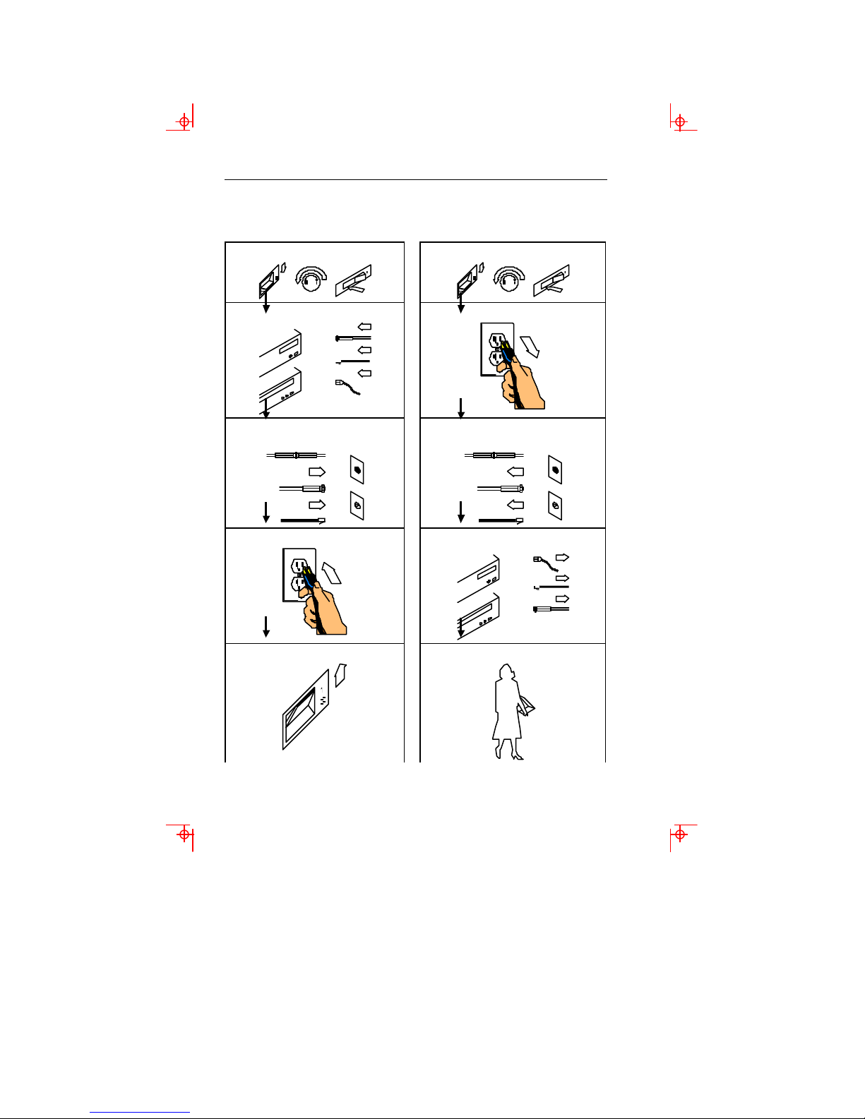
How to Connect/Disconnect the Terminal
To Connect: To Disconnect:
First, turn everything OFF.
First, turn everything OFF.
Attach all cables to devices.
Attach signal cables to
receptacles.
Attach power cord to outlet.
Turn device ON.
Remove power cord from outlet.
Remove signal cables from
receptacles.
Remove all cables from devices.
You may now take it with you.
Page 13

Notices vii
Note: In the UK, by law, the
telephone cable must be
connected after the power cord.
Note: In the UK, by law, the power
cord must be disconnected after the
telephone line cable.
Notices
References in this publication to Boundless Technologies
products, programs, or services do not imply that Boundless
Technologies intends to make these available to all countries in
which Boundless Technologies operates. Any reference to an
Boundless Technologies product, program, or service is not
intended to state or imply that only Boundless Technologies
product, program, or service may be used. Any functionally
equivalent product, program, or service that does not infringe any
of Boundless Technologies’ intellectual property rights may be
used instead of Boundless Technologies product, program, or
service. Evaluation and verification of operation in conjunction
with other products, except those expressly designated by
Boundless Technologies, are the user’s responsibility.
This publication could contain technical inaccuracies or
typographical errors.
This publication may refer to products that are announced but
are not currently available in your country. Boundless
Technologies makes no commitment to make available any
unannounced products referred to herein. The final decision to
announce any product is based on Boundless Technologies’
business and technical judgment.
The drawings and specifications contained herein shall not be
reproduced in whole or in part without the written permission of
Boundless Technologies.
Trademarks and Service Marks
The following terms are trademarks of these companies:
ADDS Viewpoint Boundless Technologies, Inc.
Centronics Centronics Data Computer
Corporation
CSA Canadian Standards Association
Page 14

viii Preface
DEC VT320/220/100 Digital Equipment Corporation
IBM International Business Machines
Corporation
MENTOR Boundless Technolog ies, Inc.
SCO Santa Cruz Operations, Inc.
TVI 925 TeleVideo Systems, Inc.
UL Underwriters Laboratories Inc.
WYSE Wyse Technology Inc.
WYSE 50/50+/60/120/150 Wyse Technology Inc.
Page 15

Electronic Emission Notices ix
Electronic Emission Notices
Federal Communication Commission (FCC) Statement
Note: This equipment has been tested and found to comply with
the limits for a Class A digital device, pursuant to Part 15 of the
FCC Rules. These limits are designed to provide reasonable
protection against harmful interference when the equipment is
operated in a commercial environment. This equipment
generates, uses, and can radiate radio frequency energy and, if
not installed and used in accordance with the instruction
manual, may cause harmful interference to radio
communications. Operation of this equipment in a residential
area is likely to cause harmful interference, in which case the
user will be required to correct the interference at his own
expense.
Properly shielded and grounded cables and connectors must be
used in order to meet FCC emission limits. Boundless
Technologies is not responsible for any radio or television
interference caused by using other than recommended cables
and connectors or by unauthorized changes or modifications to
this equipment. Unauthorized changes or modifications could
void the user's authority to operate the equipment.
This device complies with Part 15 or the FCC Rules. Operation is
subject to the following two conditions: (1) this device may not
cause harmful interference, and (2) this device must accept any
interference received, including interference that may cause
undesired operation.
Canadian Department of Communications Compliance
Statement
This equipment does not exceed Class A limits per radio noise
emissions for digital apparatus, set out in the Radio Interference
Regulation of the Canadian Department of Communications.
Avis de conformité aux normes du ministère des
Communications du Canada
Cet équipement ne dépasse pas les limites de Classe A d'émission
de bruits radioélectriques pour les appareils numériques, telles
Page 16

x Preface
que prescrites par le Règlement sur le brouillage radioélectrique
établi par le ministère des Communications du Canada.
Page 17

Electronic Emission Notices xi
Japanese Voluntary Control Council for Interference (VCCI)
Statement
This equipment is Class 1 Equipment (information equipment to
be used in commercial and industrial districts) which is in
conformance with the standard set by Voluntary Control for
Interference by Data Processing Equipment and Electronic Office
Machines (VCCI) with an aim to prevent radio interference in
commercial and industrial districts.
This equipment could cause interference to radio and television
receivers when used in and around residential districts.
Please handle the equipment properly according to the
instruction manual.
Korean Government Ministry of Communication (MOC)
Statement
Please note that this device has been approved for business
purposes with regard to electromagnetic interference. If you find
this is not suitable for your use, you may exchange it for a nonbusiness purpose one.
Page 18
xii Preface
Safety Notices
Danger Notices
A danger notice indicates a hazard that could possibly cause
death or serious personal injury.
The following danger notices are used throughout this manual.
DANGER: To prevent a possible electrical shock when installing
the device, ensure that the power cord for that device is
unplugged before installing signal cables.
DANGER: To prevent a possible electrical shock when adding the
device to a system, disconnect all power cords, if possible, from
the existing system before connecting the signal cable to that
device.
DANGER: To prevent a possible electrical shock during an
electrical storm, do not connect or disconnect cables or station
protectors for communication lines, display stations, printers,
or telephones.
DANGER: To prevent a possible electrical shock from touching two
surfaces with different electrical grounds, use one hand, when
possible, to connect or disconnect signal cables.
DANGER: To avoid a shock hazard:
þ The power cord must be connected to a properly wired and
earthed receptacle.
þ Any equipment to which this product will be attached must
also be connected to properly wired receptacles.
Page 19
Safety Notices xiii
DANGER: Electrical current from power, telephone, and
communication cables is hazardous. To avoid shock hazard,
connect and disconnect cables as shown on the following page
when installing, moving, or opening the covers of this product
or attached devices.
DANGER: The device’s switch is not the main disconnect. The
device’s main power disconnect is the detachable line cord.
Caution Notice
A caution notice indicates a hazard that could possible cause
minor personal injury.
CAUTION: This product contains a lithium battery. Do not attempt
to exchange or charge the battery. Discard the product as
instructed by local regulations for limited lithium batteries. Do
not burn.
Warning Notice
A warning notice indicates the possibility of damage to a program,
device, system, or data.
Page 20
chapter
1
Introduction
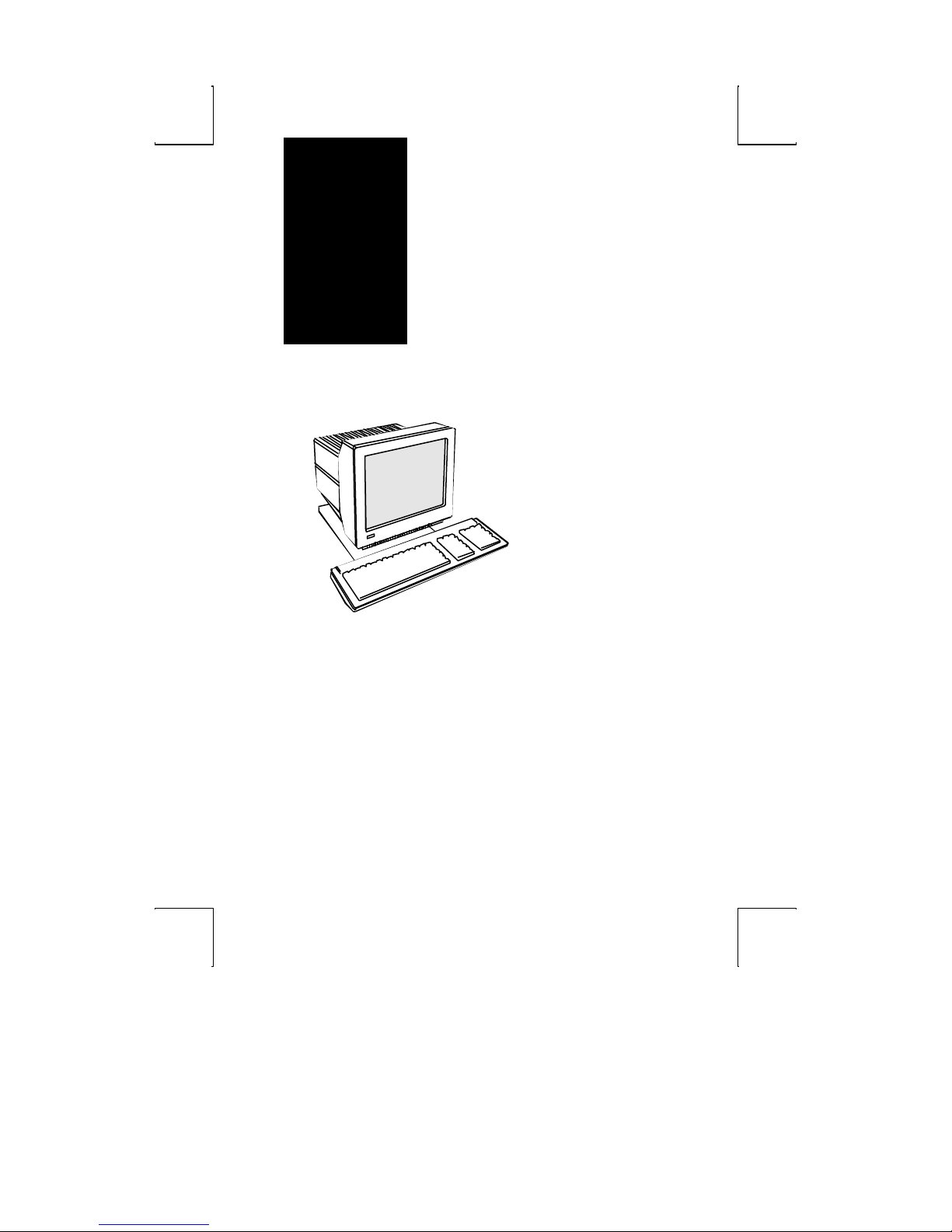
This terminal can emulate a
number of ASCII and ANSI
terminals, including PC-Term.
The keyboards supported by
the terminal are the 101/102
key extended PC (EPC), the
106/107 PC/+, and the
VT220™-style ANSI keyboards.
Clock, calendar, calculator,
ASCII chart, and diagnostic
desk accessories are
provided. Another feature is
the selectable overscan
border which can provide bezel -to-bezel video.
This terminal also features an easy-to-use Setup menu that is
configuration dependent—only the options that are valid for a
given emulation or hardware configuration are presented.
Setup also has a “Quick” menu that summarizes the options
most critical to the operation of the terminal. Travel between
menus is facilitated by function keys that are listed at the top of
every menu.
1
Page 21

2 Introduction
Features
Compatibility
◊ ADDS-Viewpoint™
◊ Wyse™ 60, Wyse 50/50+
◊ DEC™ VT-320, VT-220, VT-100
◊ PC Terminal
◊ TVI™-925
Display
◊ 100 Hz refresh rate (flicker -free)
◊ Selectable overscan borders
◊ Selectable screen saver
◊ 26, 30, 44, or 52 row display with top and bottom status lines
◊ 80 or 132 column display
◊ Double high/double wide display
◊ Up to 4 pages of memory
◊ Small footprint, tilt and swivel base
Character Sets
◊ Numerous standard, graphic, and supplemental character
sets
◊ Support for different keyboard languages: US (English), UK
(English), Danish, Finnish, French, German, Norwegian,
Portuguese, Spanish, Swedish, Dutch, Belgian-Flemish,
French-Canadian, Italian, Latin American, Swiss-French,
Swiss-German, Turkish
Page 22

Features 3
Communications
◊ Serial RS-232-C host/printer port 1, operating from 110 to
134,400 baud
◊ Serial RS-232-C host/printer port 2, operating from 110 to
38,400 baud
◊ Parallel IBM™/Centronics™ compatible printer port
Keyboards
◊ EPC 101/102-key keyboard for use in the US and
Internationally
◊ ANSI (VT220 style) keyboard
◊ PC/+ 106/107-key keyboard for use in the US and
Internationally
◊ Up to 35 shiftable and programmable edit and function keys
Desk Accessories
◊ Calculator capable of transmitting results
◊ Monthly Calendar
◊ Clock with alarm settings
◊ ASCII and Diagnostic charts
Page 23
4 Introduction
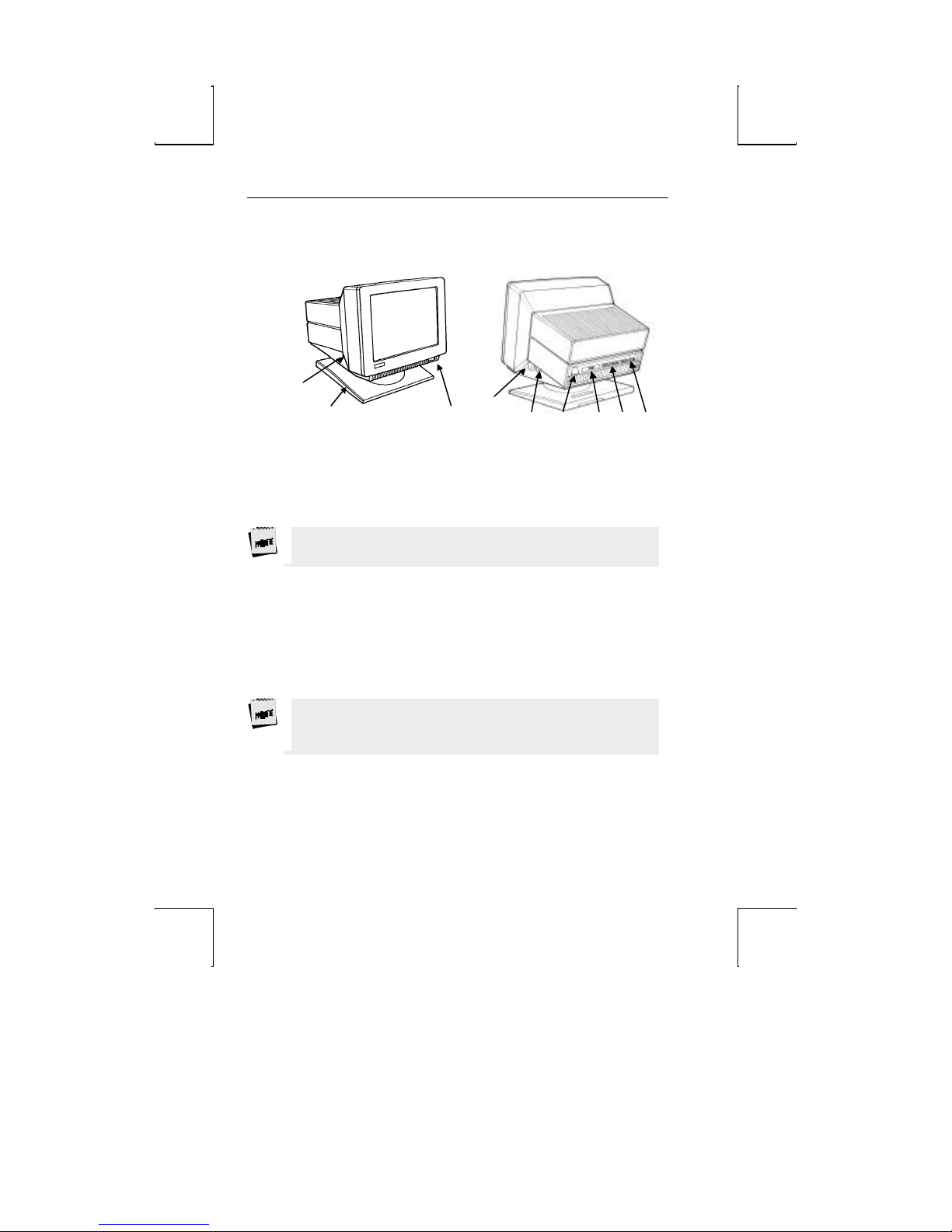
Physical Features
1
2 3
4
5 6 7 8 9
1. Keyboard Connector – push in the keyboard connector here.
2. Tilt and Swivel Base – use the tilt and swivel arrangement to
adjust the viewing angle. Grasp the lower corners of the
terminal and push up or down, or twist left or right.
3. Power Switch – “0” is off; “1” is on.
Leave the terminal’s power switch in the off position (“0”) until
power, keyboard, and communication connections are made.
4. Contrast Dial – adjust the contrast between characters of
different intensities by rotating the dial.
5. Brightness Dial – adjust the overall screen brightness by
rotating the dial.
6. Power Connection – plug the female end of the power cord into
this connector and the male end of the cord into a properly
grounded receptacle.
The Canadian Standards Association (CSA) recommends that
the power outlet be near the terminal and easily accessible at
all times.
7. Parallel Printer Port – connect the cable from the
IBM/Centronics compatible parallel printer to this port. See
the Installation chapter for options.
8. Printer Port – connect the cable from a serial printer here. See
the Installation chapter for options.
Page 24

Physical Features 5
9. Host Port – connect the cable from the host here. See the
Installation chapter for options.
Page 25
6 Introduction
Keyboards
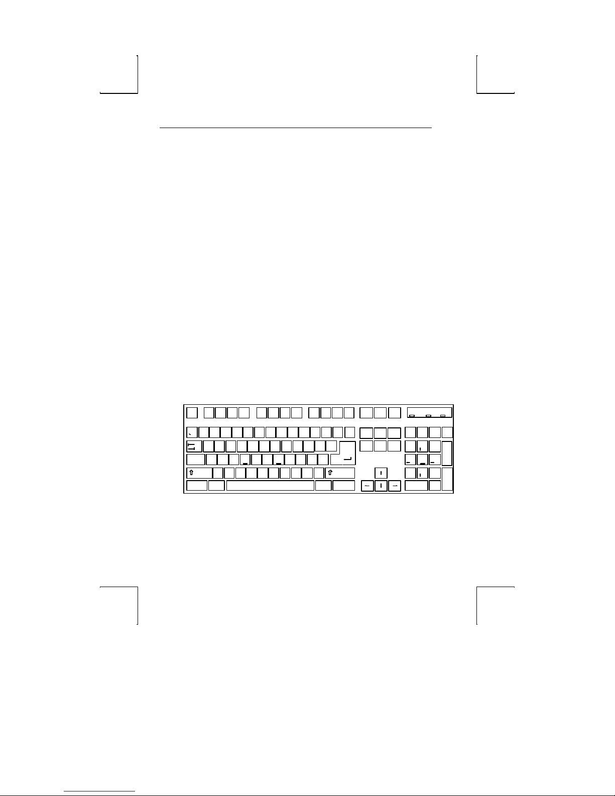
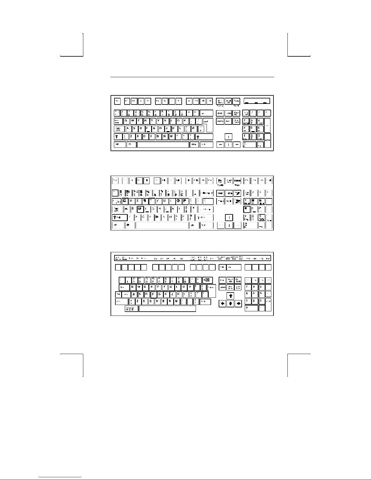
The “PC” keyboards, including the EPC (101-key) and the PC/+
(106/107-key), are similar in style and feature a number of key
groups.
The alphanumeric keypad is the main typewriter keypad, while
the function key group lies along the top of the keyboard and can
be programmed locally or downloaded from the host. The
numeric keypad is the calculator -style set of keys on the righthand side of the keyboard, used to enter numeric data.
The cursor and edit keypads, located to the left of the numeric
keypad, allows users to edit text and move around in the
document. The communication key group, above the edit
keypad, is used to control communications with the host or
printer.
The ANSI keyboard varies from the PC keyboard styles mainly in
that it features 20 function keys, a set of PF-keys, and a different
style numeric keypad.
For each keyboard, there is a set of local “hot-keys.” They
perform a variety of terminal functions, such as “Print Screen”
and “Enter Setup.” (See Appendix A for a complete list of local
functions.)
Prin t
Scroll
Scrn
Lock
SysRq Brea k
Insert
Home
Del ete En d
4
3%5
X C V B MN
Z
Alt
F4F3F2F1
^
*
FDSA G H J "LK
(9)
,
0
:
;
><
.
Esc
@2$
!
~ #
1 6&7 8
Q W E R T Y U I O P
Tab
Ca ps
Lock
Shift Sh ift
Ctrl
101-key EPC Keyboard - U.S.
_
{ }
[
'
?
/
Alt
F1 2F11F10F9F8F7F6F5
Ba ck
|
+
Spa ce
=
\
]
En ter
Ctrl
Pause
Pa ge
Up
Pa ge
Dow n
Num
Ca ps
Lock
Lock
Nu m
Lock
7 8 9
Home Pg Up
4 5 6
1 2 3
End
0
Ins
Scroll
Lo ck
-
*/
+
+
Pg Dn
En ter
.
De l
Page 26
Esc F 4F 3F 2F1
@
!
~ #
1 6&7 8
Tab
Cap s
Lo ck
Shif t Sh ift
$
2
3%5
Q W E R T Y U I O P
Z
Alt
^
4
FDSA G H J"LK
X C V B MN
(9)
*
0
><
,
.
102-key EPC Keyboard - International
Keyboards 7
Num
Cap s
Scro ll
Nu m
Caps
Pa use
Prin t
Scr oll
F1 2F11F 10F 9F8F 7F 6F 5
Scr n
L ock
|
\
En ter
Ct rlCt rl Alt
Back
Space
SysRq Bre ak
Inse rt
Ho me
Pag e
Dele te End
Do wn
Page
Up
Nu m
L ock
7 8 9
Hom e Pg Up
4 5 6
1 2 3
End
0
Ins
_
+
=
-
{ }
[
]
:
;
'
?
/
Sc roll
Lock
Loc k
L ock
L ock
L ock
Lo ck
-
/
*
+
+
Pg Dn
Ent er
.
Del
106-key PC/+ Keyboard - U.S.
ANSI Keyboard
Page 27
8 Introduction
Usage Notes
The following notations and symbols are used in this manual:
◊ Ctrl-F1: the two keys, Ctrl and F1, are to be pressed
simultaneously.
◊ Ctrl, F1: the two keys, Ctrl and F1, are to be pressed in
succession.
◊ 1-num or 1-alph: specifies that the number must be generated
either from the numeric or alphanumeric keypads.
◊ 23h: the number 23 is represented in hexadecimal (hex)
notation.
◊ applies to ASCII emulations only: ADDS-VP, Wyse 50+,
Wyse 60, PC Term, and TVI-925.
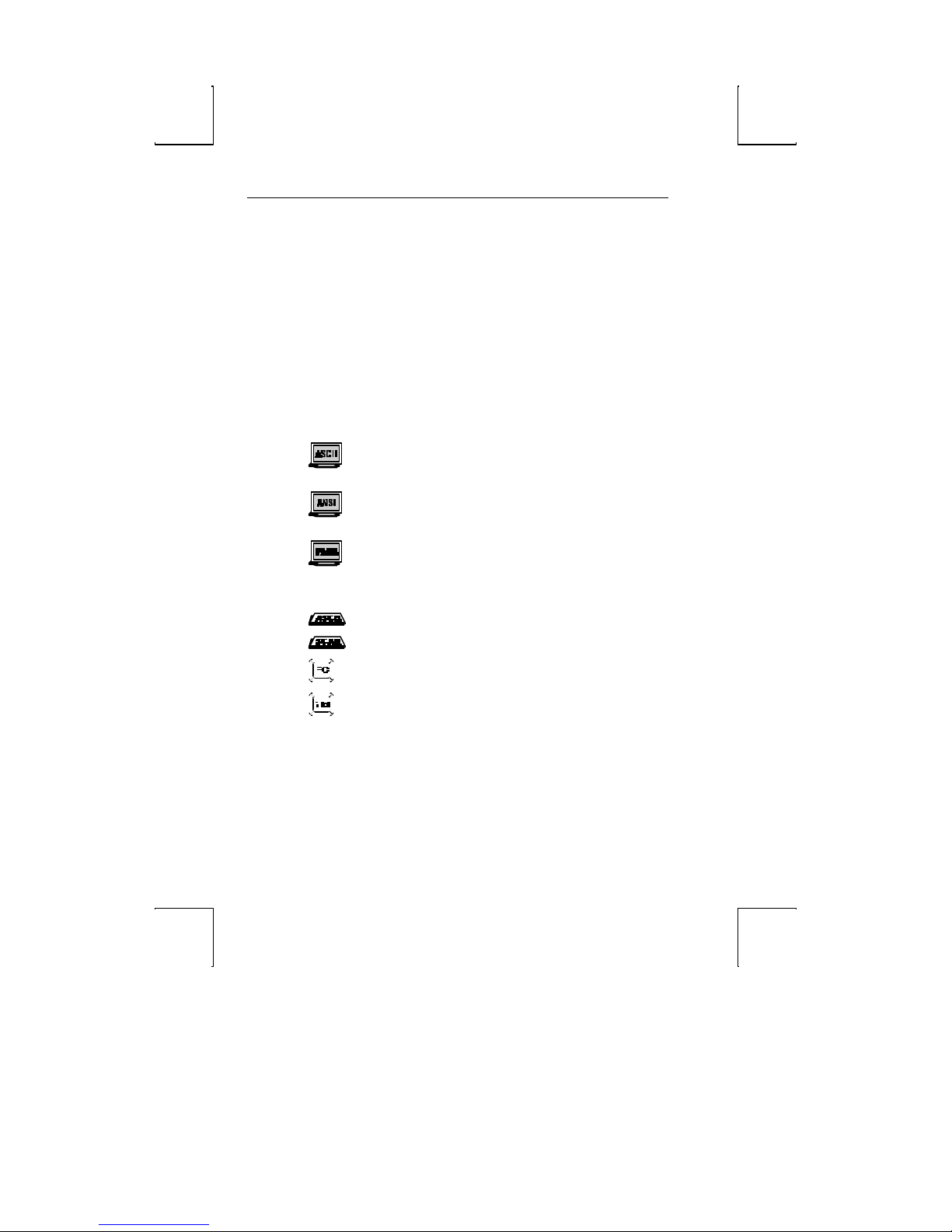
◊ applies to ANSI emulations only: VT300/8, VT300/7,
VT200/8, VT200/7, and VT100.
◊ applies to parallel attribute emulations only: includes
all emulations except ADDS-VP and Wyse 50+ (which are field
attribute emulations).
◊ applies to ASCII key mode only.
◊ applies only to Scan Code key mode.
◊ applies to the PC/+ or EPC keyboards only.
◊ applies to the ANSI keyboard only.
Page 28

Communications 9
Communications
This terminal is equipped with three ports. The two serial ports
are intended for connecting to either a host/modem or a serial
printer. The remaining port is a Centronics-compatible printer
port. The port you use as the printer port depends on whether
you have a serial or a parallel interface to the printer.
The first host/printer serial port (SES1 -EIA) can communicate
with your computer or printer at a baud rate of 110 to 134,400
baud (bits per second). The second host/printer serial port
(SES2-AUX) can communicate at speeds from 110 baud to 38,400
baud. Either port can be used to connect to a host
computer/modem or serial printer.
You have the choice of using either the second serial port or the
parallel printer port as your printer interface. Refer to the
following sections for further information on these ports.
Receive Flow Control
Because devices can receive data faster than they can process it,
data flow control (selectable in the PORTS menu of Setup)
should be used to prevent data loss. Software flow control relies
on the Xon and Xoff characters (“g” and “e” characters in Scan
Code key mode) to indicate when the terminal is able or unable
to store further data. The Xon signal transmits the DC1
character (11h) and the Xoff signal transmits DC3 (13h).
When “EIA (or Aux) Rcv” in the Setup menu for PORTS is
“Xon-Xoff,” the terminal issues an Xoff character, indicating to
the host that it should stop transmitting data. The terminal will
then continue to process data until its receive buffer is empty. It
will then issue an Xon character to the host, indicating that it
can resume sending data to the terminal.
Page 29

10 Introduction
If the “EIA (or Aux) Rcv” is “No Protocol” in Setup, the terminal
will continue to accept characters into its receive buffer until it
is full. Additional characters will be lost. Xon-Xoff protocol must
also be set on the host computer or printer for proper
handshaking.
In addition to software “receive” flow control (Xon-Xoff), the serial
host/printer ports support “receive” hardware flow control. The
SES1-EIA port has an outgoing DTR (Data Terminal Ready) signal.
If “EIA Rec” is “DTR” in Setup, and the terminal’s receive buffer
fills to the level mentioned above, the terminal will set the DTR
signal low to inform the host (serial) device to stop sending data.
On the SES2 -AUX port, if “Aux Recv” is “DSR” in Setup, the
outgoing DSR (Data Set Ready) signal serves to signal the host
(serial) device that the terminal is not ready to receive more data.
Transmit Flow Control
Likewise, the terminal will understand the Xon and Xoff requests
from the host when it is transmitting data (provided the “EIA (or
Aux) Xmt” is “Xon-Xoff” in Setup). This is referred to as
“transmit” flow control.
This terminal will stop transmitting data to the host or printer
when it receives an Xoff (DC3) code. If, however, the terminal
needs to send a receive protocol character, it will transmit that
character even if it has received an Xoff code. When the terminal
stops transmitting, the data will be buffered in the transmit
buffer. Once the buffer is full, additional keyboard data will be
lost. When an Xon (DC1) character is received, the terminal can
again send data to the attached serial device.
In addition to software “transmit” flow control (Xon-Xoff), the
serial host/printer ports support “transmit” hardware flow
control. DSR on the SES1 -EIA port and DTR on the SES2-AUX
port monitor serial devices to control the flow of data to them
(provided EIA and AUX Xmit are “DSR” and “DTR”, respectively, in
Setup).
Page 30
Communications 11
For parallel printers, this terminal monitors the BUSY and ERROR
signals which are sent by the printer to determine when data
transmission should be stopped or resumed.
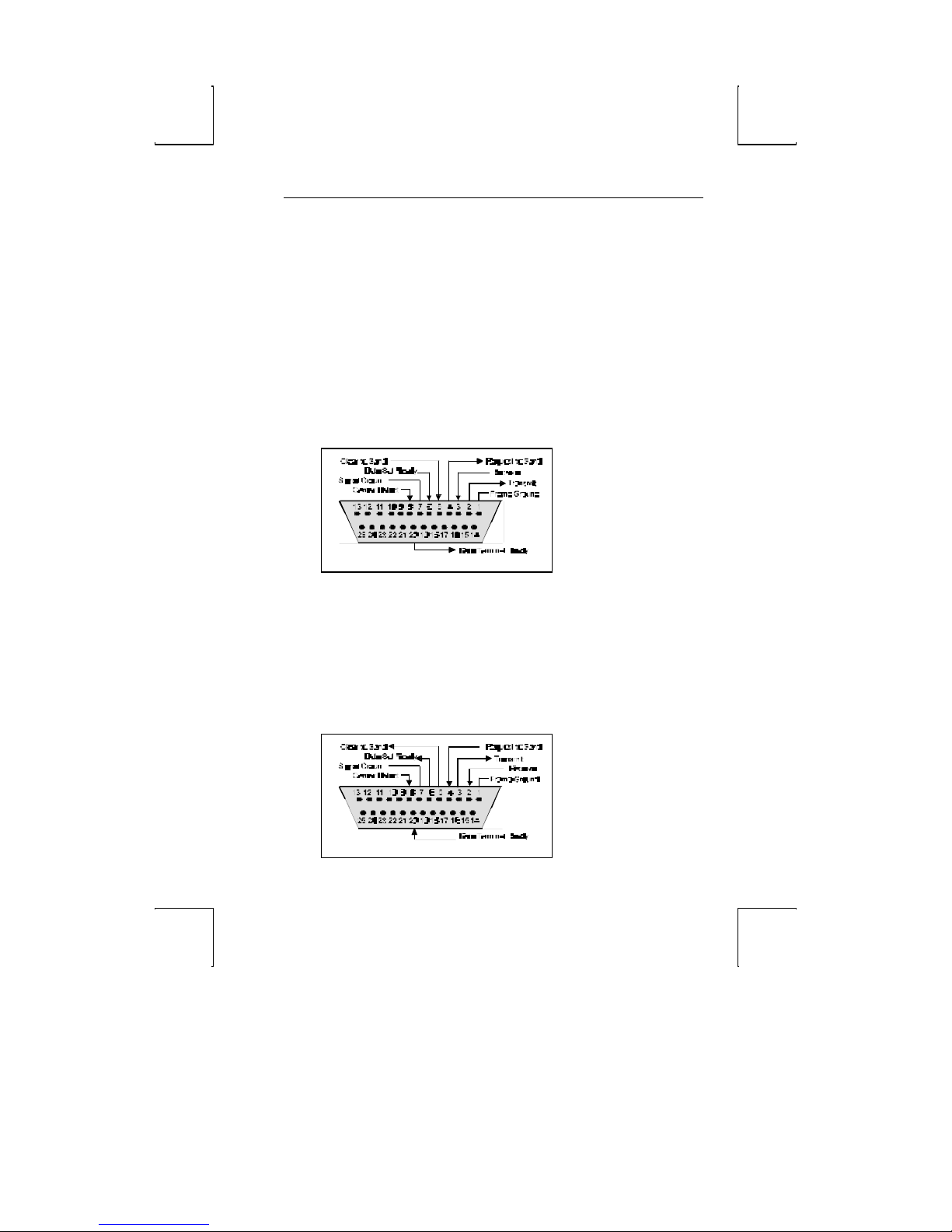
Host/Printer Port 1
This port, labeled “SES1 -EIA,” is designed for connection to the
host (computer or modem) or a serial printer via a 25-pin D-shell
(DB25P) female connector. This port uses an RS-232-C
communication interface, is configured as a DTE (Data Terminal
Equipment) device, and can operate from 110 to 134,400 baud.
The pins supported are shown below:
Host/Printer Port 1 Pin Assignments
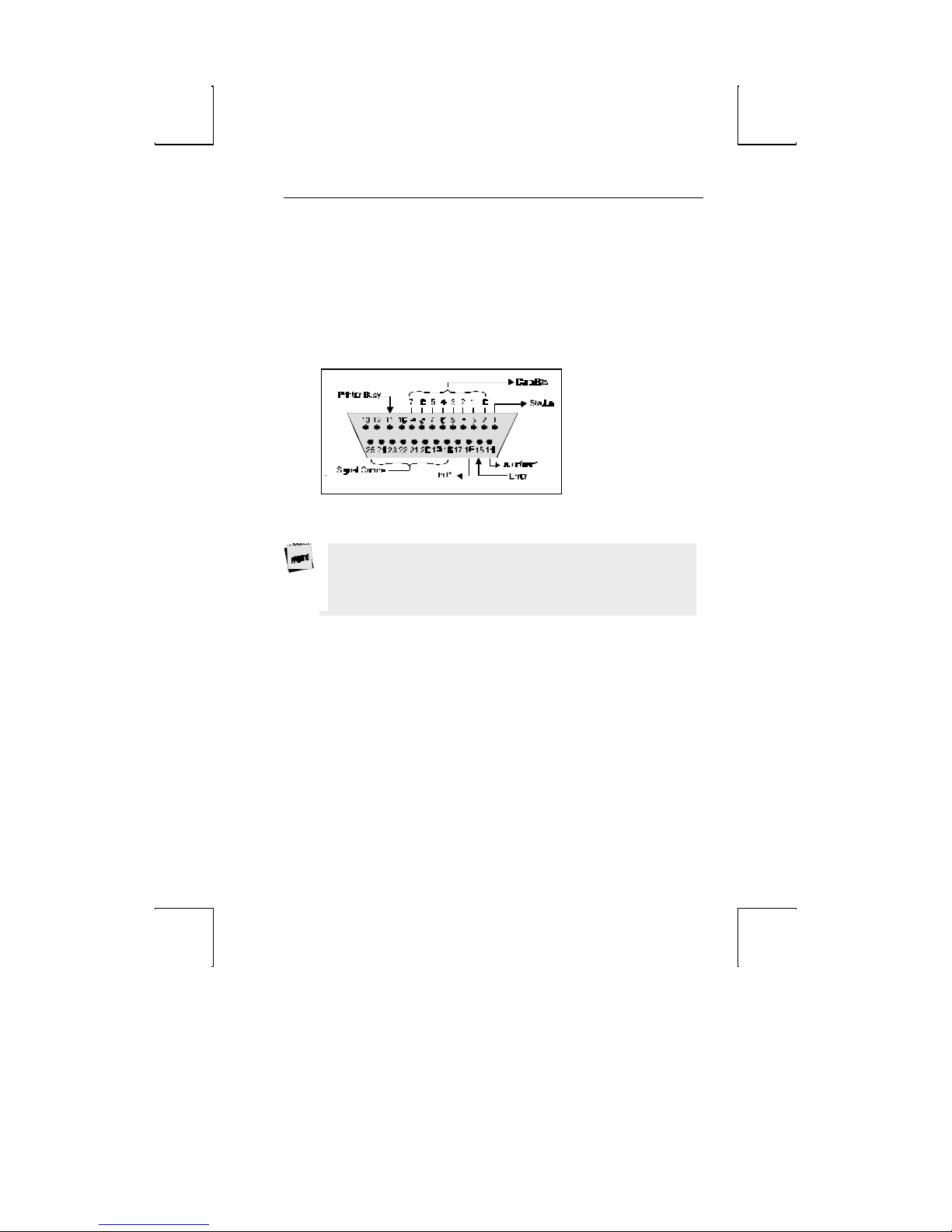
Host/Printer Port 2
This port, labeled “SES2 -AUX,” is designed to connect to a host
connection (computer or modem) or a serial printer, and can
operate from 110 to 38,400 baud. This port uses an RS-232-C
interface via a DB25P female connector, and is configured as a
DCE (Data Communication Equipment) device. The pin
assignments for this port are shown below:
Page 31

12 Introduction
Host/Printer Port 2 Pin Assignments
Refer to the Installation chapter for details on the connection
of all ports to serial devices (hosts, modems, or printers).
Page 32
Communications 13
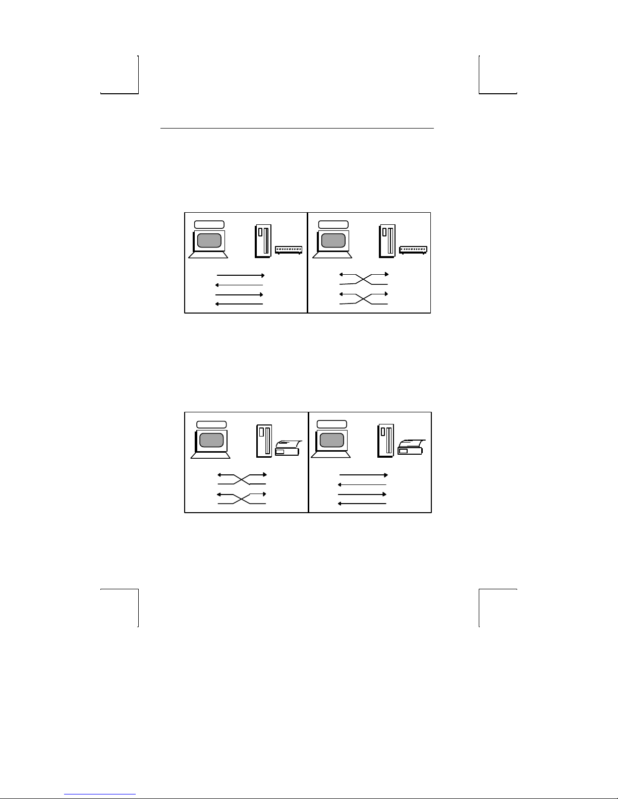
Parallel Printer Port
This port, labeled “PAR,” is designed for connection to a parallel
printer, which has a Centronics interface with a 25-pin D-shell
female connector. This port, unlike the others, is a unidirectional device—it only serves to output data to the printer
and cannot receive data. The pins and signals supported are
shown below:
Parallel Port Pin Assignments
* These signals are held high, in an inactive state.
If you have opted to use a parallel printer, but it is not
connected, an error message will appear on the status line
when any PRINT operation is done. To clear the message,
press Ctrl-Shift-Tab.
Page 33
14 Introduction
SES1 EIA
DTR
pin2
pin3
pin6
SES2 AUX
pin2
pin3
pin6
SES2 AUX
DTR
pin2
pin3
pin6
SES1 EIA
Host
DTR
pin2
pin3
pin6
Terminal to Modem (DCE) or Host
Refer to the diagram below to understand why a null modem
adapter may be needed when connecting the second serial port
(SES2-AUX) to a modem or a DCE host. The first serial port will
connect directly without a null modem since it is a DTE device.
Host
Host
DTE
Transmit
Receive
DSR
pin2
pin3
pin20
pin6
pin20
D
C
E
Transmit
Receive
DTR
DSR
Modem
DCE
Receive
Transmit
DTR
DSR
pin2
pin3
pin20
pin6
pin20
D
C
E
Modem
Transmit
Receive
DTR
DSR
Terminal to Host (DTE) or Printer
Refer to the diagram below to understand why a null modem
adapter may be needed when connecting the first serial port
(SES1-EIA) to a host port without a modem (most serial printers
are DTE devices and most hosts are not). The second port (AUX)
will connect directly, without a null modem, since it is a DCE
device.
Host
Serial
Printer
D
T
DTE
Transmit
Receive
DSR
pin2
pin3
pin20
pin6
pin20
E
Transmit
Receive
DTR
DSR
DCE
Receive
Transmit
DSR
pin2
pin3
pin20
pin6
pin20
D
T
E
Transmit
Receive
DTR
DSR
Serial
Printer
Page 34

Screen Display and Pages 15
Screen Display and Pages
This terminal offers a variety of screen lengths including 26, 30,
44, or 52 lines. These numbers include the top and bottom
status lines (or label line), as well as the lines used to display
data. A “page” of terminal memory represents the total number of
lines that can be accessed, whether or not they are all viewable
on the screen at once. Refer to Appendix A for the number and
lengths of pages available for your setup.
The page length is comprised of a base page length multiplied by
1,2,4, or 8. For instance, in certain modes, 24 (24x1), 48 (24x2),
and 96 (24x4) ar e available, the same way that 25(25x1), 50
(25x2), and 100 (25x4) are. The base page length and the screen
size determine whether a bottom status line or label line is
displayed or not.
Bottom Status/Label Line Display
With a screen length of “26 lines,” the page lengths that are
multiples of 24 allow the bottom status/label line to be displayed,
while those that are multiples of 25 do not. The same idea
applies with the 44 line screen size. A page length with 42 lines
as a base page size will display a label line, while the 43 line base
page length will not. An exception to this rule is if the screen
length is significantly larger than the that page size, then the
label line is displayed, such as if the screen is 44 lines and the
page length is 25 lines.
Page 35
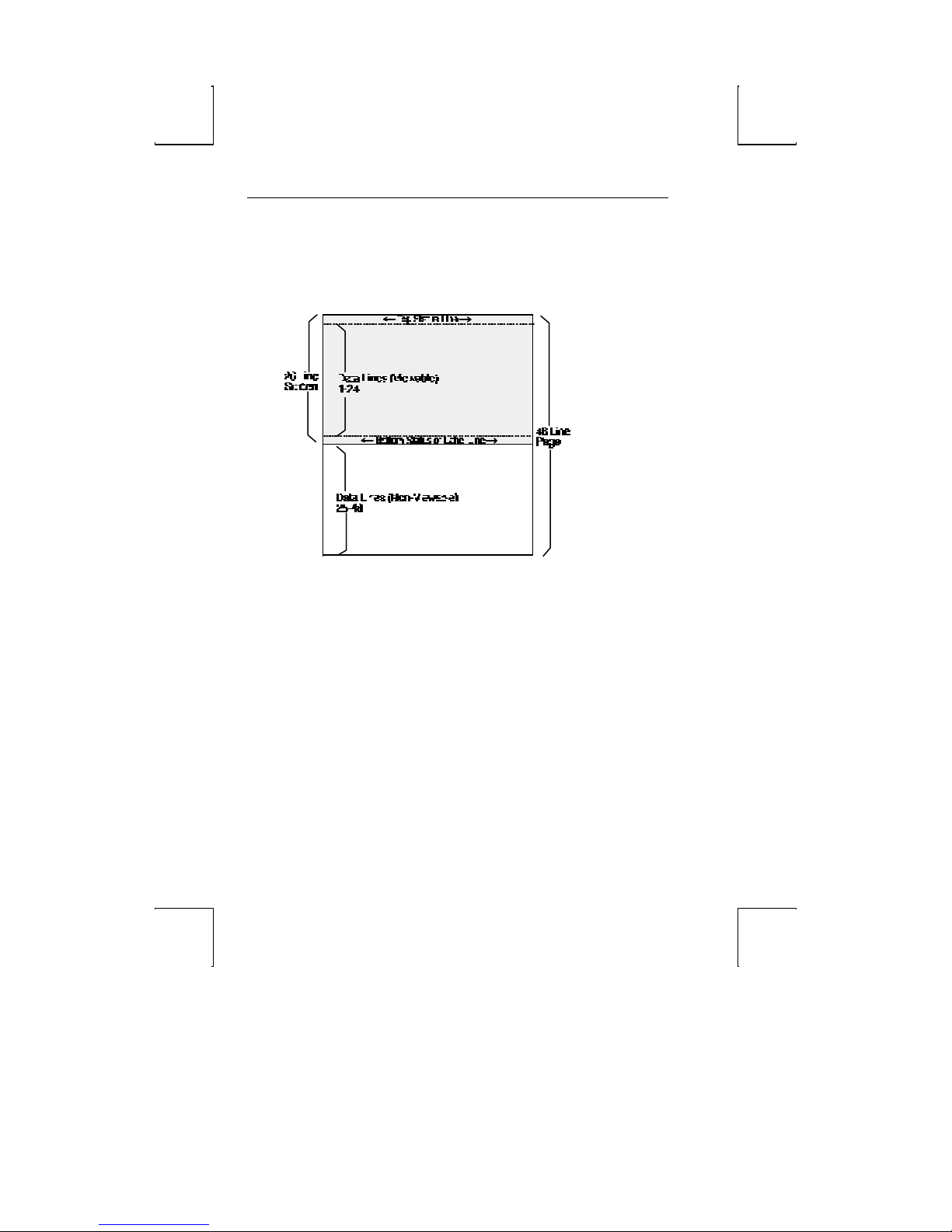
16 Introduction
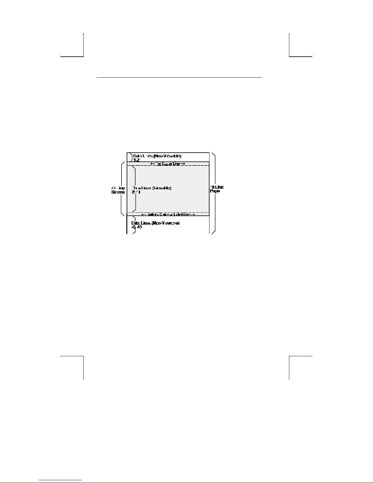
The figure below represents the entire page memory of a 48 line
page (24 base page length times a multiplier of 2) and the portion
of the page that is viewable on the display screen, when “26
Lines” is selected. Notice that the label line is visible in this
mode.
Visual Effects of Screen and Page Lengths
The combination of page and screen lengths influence the
number of displayable data lines. For example, if the page length
is “50” (25 x 2), and the screen length is 44 lines, the number of
data lines that are visible at any one time is 43, with no label line
(the other line is used for the top status line). On a 52 line
screen, 50 of the 52 data lines are visible at one time.
If the page length is shorter than the screen length, blank lines
are present below the data line or status/label line. If the page
length is larger than the allowable number of data lines, some of
the rows are out of view. In order to bring them into view,
“scrolling” or “panning” is used as necessary.
Scrolling causes a new line to scroll into view when the cursor
advances past the last or first row on the page. If the cursor
moves past the last row, the top row of text is lost; if past the first
Page 36

Screen Display and Pages 17
row, the bottom row of text is lost (if Auto Scroll is “on” in Setup).
Note that text scrolled off the screen is not recoverable.
Page 37
18 Introduction
If the current page or portion of the page is longer than the
screen display or window in which it is displayed, local keystrokes
can be used to “pan” the window up or down (Ctrl-↑ and Ctrl-↓).
As a window is panned up, the page appears to be moving down;
the opposite is true when panning the window down. Text that
is panned off the screen is out of view, but is not lost.
The figure below represents the display screen with a 48 line
page length on a 44 line screen, after panning the window down
2 lines.
Page 38

Screen Display and Pages 19
This page is
intentionally
left blank.
Page 39

chapter
2
Installation
This section provides a “walk-through” approach to the
installation of your terminal. This will enable you to physically
connect the terminal to a printer and a host computer/modem,
as well as to configure the Setup menu to suit your requirements
and preferences.
The terminal is designed to provide great flexibility in configuring
the terminal. An example of the flexibility is apparent in the fact
that either the EIA or Aux ports can be used to connect either to
a host or a printer port.
The procedures described here are among the most common.
Described here are conventional setups, with or without a
printer. These steps may need to be adjusted to meet your
requirements.
STEP 1 – Know Your Devices
The first step in our installation process will be to determine
what type of serial ports you are connecting to the terminal. The
Communications section in the Introduction chapter describes
the differences between a DTE and DCE serial device. Determine
what type of devices you are using (a DTE host, a DCE modem, a
DTE printer, a parallel printer, etc.).
17
Page 40

18 Installation
STEP 2 – Physical Connections
Depending on the types of serial interfaces of your devices, you
may need one or more “null modem” adapters to com municate
properly.
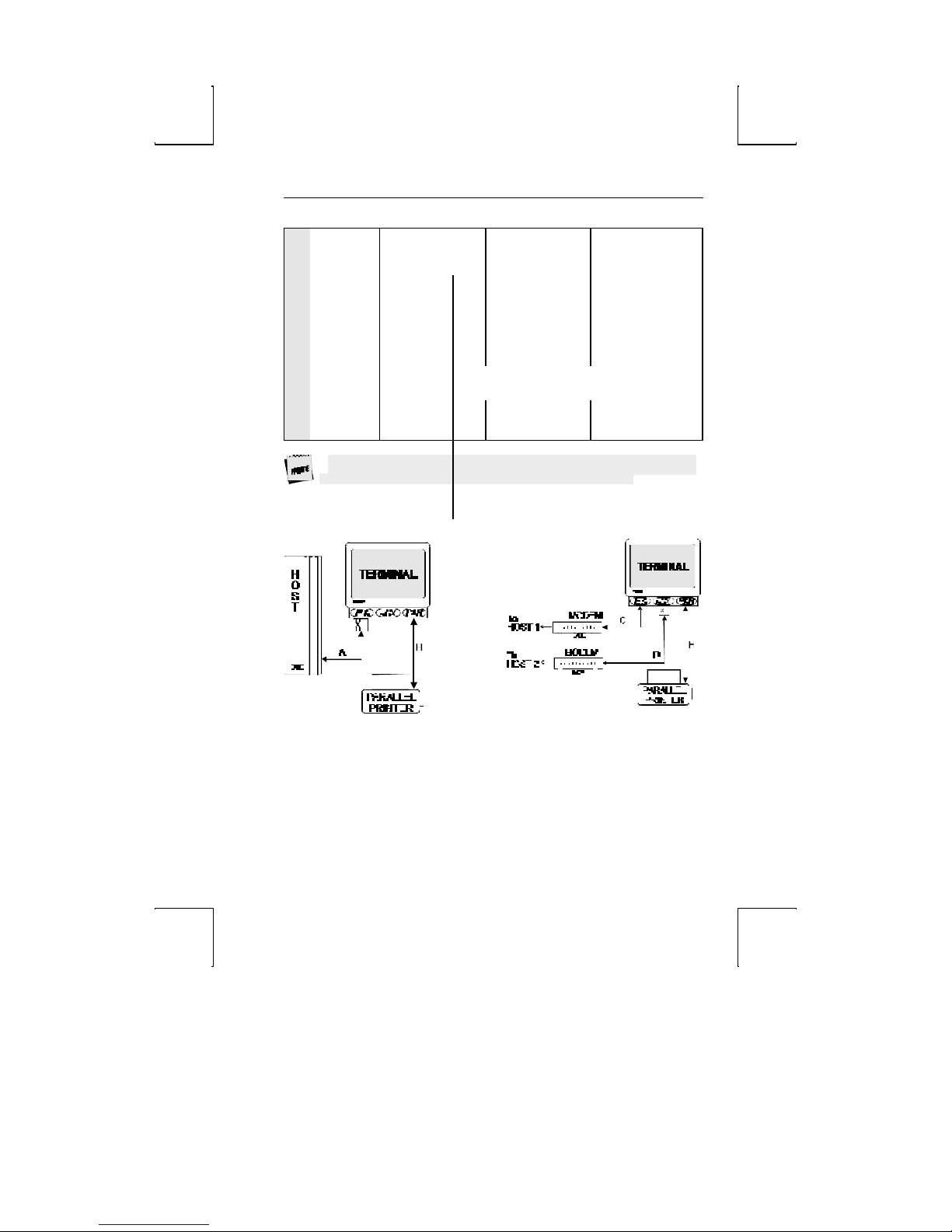
First, refer to the Common Setups diagrams later in this chapter.
If one of these setups matches your needs, make the connections
as shown in the diagrams by referring to the Host/Printer
Connection. Each cable connection in the diagram (the lines
with arrows on each end) has a letter next to it.
The letters correspond to the letters in the Host/Printer
Connection Guide. If these setups don’t apply, choose the
connections in the Host/Printer Connection Guide that are
appropriate.
Your physical connections are now complete.
STEP 3 – No Printer Option
If you did not opt to install a printer (did not complete E, F, G, or
H), you must set the Printer portion of the Host/Printer selection
in the Quick (F1) Setup menu to “None.” Choose the
combination of Host/Printer that properly represents which
terminal port you are connecting the host to, and “None” as the
printer. For example, if the EIA port is connected to the host or
modem, the setting would be “EIA/None.”
STEP 4 – Know Your Seria l Port(s) Protocol
Consult your system administrator to find out the communication
settings on all the serial devices you are connected to, including
EIA (or Aux) baud, data bits, stop bits, parity, parity checking
on/off, and transmit and receive flow control protocol. This could
include a host/modem, or a serial printer. Record this
information in the User Settings Chart later in this chapter for
reference in Step 7.
Page 41

STEP 5 – Communications Setup Selections 19
STEP 5 – Communications Setup Selections
To complete this step, you must recall the letters next to the
connections that you made in Step 2.
The procedures below correspond directly to the individual
connections made. Notice that only certain connection
procedures are to be followed, not all of them. For example, if
you have made connections “C” and “F” to a modem and a serial
printer, then follow connection procedures “C” and “F” below.
Only follow those steps that apply to your connections (A-H).
To access the Setup menu, press Ctrl-Scroll Lock on a PC
keyboard or F3 on an ANSI keyboard.
Connection A: Host DCE
1. Enter the Setup menu.
2. In the Setup Quick (F1) menu, set the Host portion of the
“Host/Printer” selection to “EIA” without changing the
current Printer option (“EIA/xxxx”). The Printer will be set in
another connection procedure if needed.
3. In the Ports (F6) menu, set the proper communications
settings for the EIA Baud, EIA Data Format, EIA Parity Check,
EIA Recv, and EIA Xmt selections. See the Setup chapter for
more information on the individual settings.
Connection B: Host DTE
1. Enter the Setup menu.
2. In the Setup Quick (F1) menu, set the Host portion of the
“Host/Printer” selection to “Aux” without changing the
current Printer option (“Aux/xxxx”). The Printer will be set
in another connection procedure if needed.
3. In the Ports (F6) menu, set the proper communications
settings for the Aux Baud, Aux Data Format, Aux Parity
Page 42

20 Installation
Check, Aux Recv, and Aux Xmt. See the Setup chapter for
more information on the individual settings.
Connection C: RS-232 with Modem
1. Follow all proc edures of Connection A, steps 1 through 3.
2. If you are connecting to a modem, set the “EIA Modem
Control” parameter to “On” in the Ports (F6) menu.
Connection D: RS-232-C with Modem
1. Follow all procedures of Connection B, steps 1 through 3.
2. If you are connecting to a modem, set the “Aux Modem
Control” parameter to “On” in the Ports (F6) menu.
Connection E: Printer
1. In the Setup Quick (F1) menu, set the Printer portion of the
“Host/Printer” selection to “EIA” without changing the
current Host option (“xxxx/EIA”). The Host will be set in
another connection procedure if needed.
2. Follow procedure of Connection A, step 3.
Connection F: RS-232-C Printer
1. In the Setup Quick (F1) menu, set the Printer portion of the
“Host/Printer” selection to “Aux” without changing the
current Host option (“xxxx/Aux”). The Host will be set in
another connection procedure if needed.
2. Follow procedure of Connection B, step 3.
Connections G and H: Parallel Printer
1. Enter the Setup menu.
2. In the Setup Quick (F1) menu, set the Printer portion of the
“Host/Printer” selection to “Para” without changing the
current Host option (“xxxx/ Para”).
Page 43
STEP 8 – Emulation Setup Selection 21
STEP 8 – Emulation Setup Selection
This step requires setting a selection in the Setup menu to
configure the “Emulation” of the terminal. Determine which
emulation your applications run with.
Enter the Setup menu and set the “Emulation” parameter, in the
Quick (F1) menu, to match your requirements.
STEP 9 – Additional Setup Options
At this point, you should proceed to the Setup chapter and
continue to set up your own selections for any other parameters
such as those for the display, keyboard, function/edit keys, and
tabs.
STEP 10 – Save Parameters
Finally, remember to save your Setup parameters in permanent
memory, so that they can be recovered if the terminal is powered
down. When you exit the Setup menu, the prompt “Save all?
(Y/N)” flashes. To save parameters, press “Y”. Another way to
save parameters is to perform a “Save Terminal” operation, while
in the Exec (F13/Prnt Scrn) menu of Setup.
Remember to save your Setup settings after the entire
installation process.
STEP 11 – Establish Communications
Your installation is now complete. By pressing the Return or
Enter key, you should be able to communicate with the host
computer(s). The printer should respond to the local print
command, Shift-Ctrl-. (period on numeric keypad).
If for some reason, your installation was not successful, make
sure your physical connections are secure, that the
communications protocol settings match your devices, and that
Page 44

22 Installation
the Setup selections are chosen to provide a proper interface
between the terminal and your devices.
If you continue to have problems installing the terminal, call your
local dealer for technical support.
Page 45
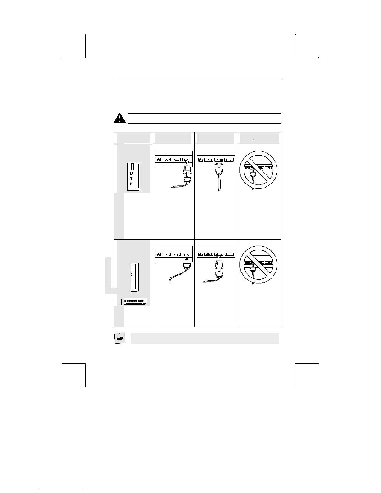
Host/Printer Connection Guide
CAUTION: Do not (un)plug in electrical storm.
DTE Host*
SES1-EIA (DTE) SES2-AUX (DCE) PAR
Host/Printer Connection Guide 23
Connection A:
Connect a null
modem adapter
between the host
cable and the EIA
port.
Connection B:
Connect the host
cable directly to
the AUX port.
Not applicable.
DCE Host
or Modem
Connection C:
Connect the host
or modem cable
directly to the EIA
port.
Connection D:
Connect a null
modem adapter
between the host
or modem cable
and the AUX port.
Not applicable.
* Most host computers are configured as a DTE device. The
Page 46
24 Installation
Mentor® System is an example of a DCE host system.
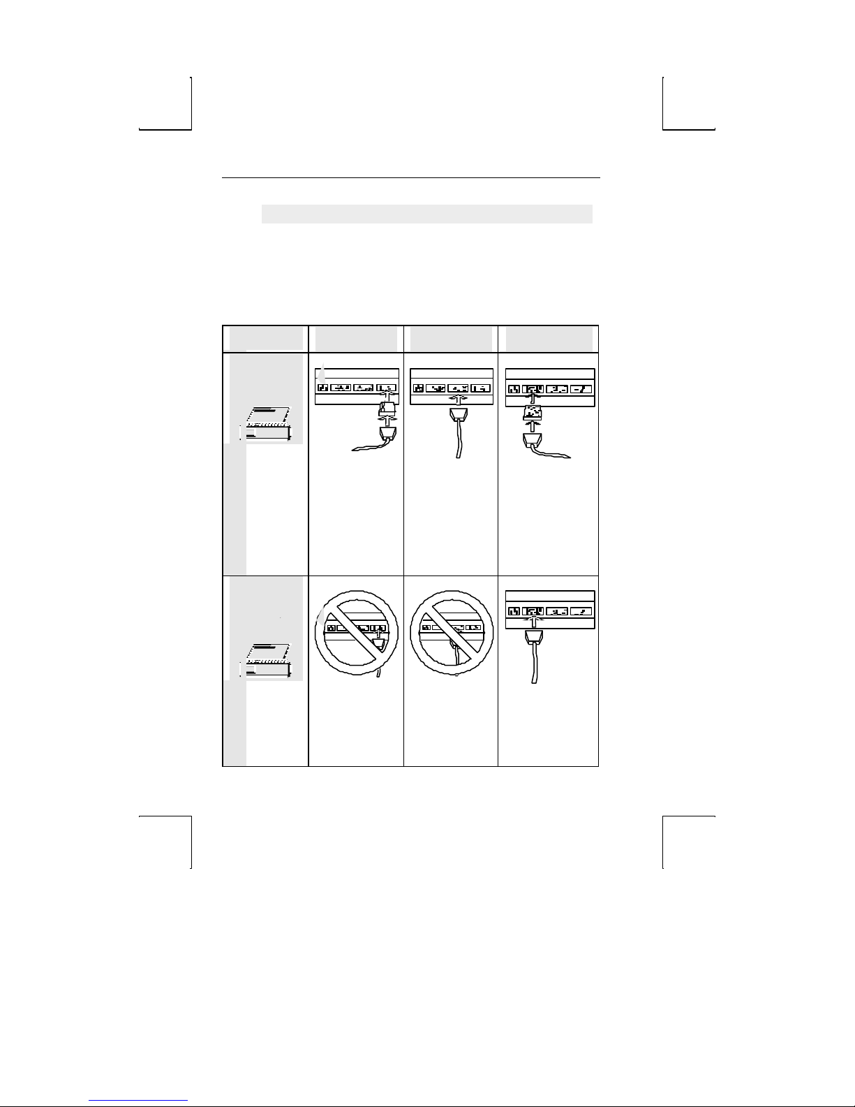
DTE Serial
Printer**
Parallel Printer
(Centronics//
IBM)IBM)
SES1-EIA (DTE) SES2-AUX (DCE) PAR
Connection E:
Connect a null
modem adapter
between the serial
printer cable and
the EIA port.
Not applicable.
Connection F:
Connect the serial
printer cable
directly to the
AUX port.
Not applicable.
Connection G:
This is an option if
you connect a
parallel-to-serial
converter between
the serial printer
cable and the PAR
port.
Connection H:
Connect the parallel
printer cable to the
PAR port.
Page 47
SERIAL
** Most serial printers are configured as DTE devices.
Common Setups
Common Setups 25
F
PRINTER
Sessions=One
Host/Printer=Aux/Para
Aux Baud, Data Format, etc. matches
the host
Sessions=One
Host/Printer=EIA/Aux
EIA Baud, etc. matches the host
Aux Baud, etc. matches the printer
EIA Modem Control=On
Page 48
26 Installation
User Settings
Use the chart below to document your system and terminal settings:
Parameters Examples: Your Settings:
Connections made
Host/Printer
Emulations
Host: Baud
Data Bits
Stop Bits
Parity
Parity Check
Flow Control (In)*
Flow Control (Out)**
Modem Control
C and H
EIA/Para
ADDS-VP
9600
8
1
None
Off
Xon-Xoff
Xon-Xoff
On
Notes: * Incoming flow control on the host should correspond to “EIA (or Aux)
** Outgoing flow control on the host should correspond to “EIA (or Aux)
Rcv.”
Xmt.”
Page 49

chapter
3
Setup
The Setup menu is your control panel for this terminal. It
permits you to configure the terminal to communicate with the
host computer as well as to suit your personal preferences.
Overview
The Set up menus have been designed to allow maximum
flexibility with a minimum investment of time. Thirteen menus
provide you with the flexibility and the features below contribute
to ease of use:
þ The Quick menu is the first screen upon entry. It contains
the parameters critical to the operation of the terminal with
the host.
þ Function keys permit easy access to any menu. The function
keys are labeled at the top of every menu.
þ Setup is “smart.” That is, it provides only the options that are
valid for the hardware and current emulation.
þ Keystrokes and Help Messages are at the bottom of every
menu.
þ Valid choices for the selected parameter are displayed at the
bottom of the menu.
25
Page 50
26 Setup
Entry and Exit
EPC Keyboard: Press Ctrl-Scroll Lock to both enter and exit
setup. Also, press F14 or Pause to exit.
ANSI Keyboard: entry is dependent upon the Setup selections:
þ When “F1 to F5 keys” = Local, press F1 to enter.
þ When “F1 to F5 keys” = FKey, press Ctrl-F3 to enter.
þ When “Key Mode” = Scan Code, press Ctrl-Select to enter.
Saving Parameters
Upon exiting setup mode, the prompt “Save All (Y/N)” blinks.
Press Y or y to exit setup and save settings in permanent
(nonvolatile) RAM. Press C or c to cancel the exit request. Press
N or n to exit Setup. The changes will take effect, but will be lost
if the terminal is reset or powered off.
An exception to this is function/edit key and answerback
message programming. Once edited in Setup, the changes are
saved regardless of the way in which you exit Setup.
Page 51
Overview 27
Movement Inside Menus
F1 through F12: Select the menu that corresponds to the function
key. Depending on your keyboard, there will be another key,
either F13 or the Print Screen key (on the EPC keyboard)
available to access the “EXEC” menu. These keys are always
active within Setup. The keys are labeled at the top of each
menu.
Cursor Control Keys (↑ ← ↓ →): These keys control movement to
parameters within the menu and is indicated by a highlighted
selection bar. This selection bar will wrap to the other side of the
menu at the top, bottom and side boundaries. For each
parameter there are at least two choices. As the parameter is
highlighted, the available choices appear in the area above the
help bar.
Some parameters are action fields and have no choices. See
the Action Fields section later in this chapter.
Enter and Shift-Enter: Cycle “up” or “down” through the choices for a
given parameter.
The following keystrokes are also available but are not
documented in the Setup help bar.
Tab and Shift-Tab: Move from menu to menu forward or backward
without using function keys.
Space and Shift-Space: Cycle through the list of choices. Same as
Enter and Shift-Enter.
Parameters that are changed are executed as soon as that field is
exited. Page resets may occur when certain choices are made in
Setup.
Action Fields
Certain parameters are not selections but action fields. When
the action field is highlighted and then selected, the action is
taken. A “WAIT” message may appear at the top right portion of
the screen, and when the action is completed, a “DONE” message
Page 52

28 Setup
will appear. These messages are cleared when the selection bar
is placed on another parameter.
Setup Map
Key Menu Parameters Available
(Not all will display for a given emulation, keyboard, or video mode)
F1 Quick Emulation Comm Mode EIA/AUX Baud Rate
Enhanced EIA/AUX Data Format Language
Host/Printer
F2 General Emulation Enhanced Auto Wrap
Auto Font Load Auto Page Auto Scroll
Monitor Mode Screen Saver Bell Volume
Warning Bell Host/Printer Bell Length
F3 Display Page Length Screen Video Cursor
Display Cursor Scroll Overscan Borders
Columns Width Change Clear Auto Adjust Cursor
Screen Length Speed Scroll Speed
Refresh Rate
F4 Keyboard Language Key Repeat Keyclick
Margin Bell Key Mode Char Set Mode
Key Lock Key Rate Caps Lock
Num Lock Keyboard Layout Code Page
F5 Keys Enter Key Return Key Backspace
Alt Key Pound Key Local Leadin
Return Key Repeat Desk Acc Disconnect
UDKs
Keys Enter Key Return Key DEL key
Compose Key Pound Key Local Leadin
Page 53

Setup Map 29
Return Key Repeat F1 to F5 keys Disconnect
.. and ,, key
UDKs
and ~ <> key
`
Page 54

Setup Map 30
F6 Ports EIA Baud Rate EIA Data Format EIA Parity Check
Aux Baud Rate Aux Data Format Aux Parity Check
EIA Xmt EIA Recv EIA Xmt Pace
Aux Xmit Aux Recv Aux Xmt Pace
EIA Break EIA Modem Control EIA Disconnect
Aux Break Aux Modem Control Aux Disconnect
F7 Host Comm Mode Local Recv <CR>
Recv <DEL> Send ACK Send Line Term
Send Block Term Send Region Send End
Null Suppress
F8 Print Prnt Line Term Prnt Block Term Prnt Region
Prnt Mode Secondary Recv
F9 Emulation Attribute Bright Video Enhanced Attributes
Page Edit WPRT Intensity WPRT Reverse
WPRT Underline WPRT Blink Display NV Labels
Save Labels Char Set Status Line
Fkey Speed
Emulation Numeric Kpd Cursor Kpd Send Data
Print ANSI-ID Function Key Lock
Key Usage Feature Lock Char Set
Status Line
F10 Tabs Auto Init Tabs Default Tabs
F11 Answerback Answerback Mode Answerback Conceal
F12 Program Key Program Key Dir
PrtSc Execute Save Terminal Recall Terminal Default Terminal
Save Emulation Recall Emulation Default Emulation
Reset Terminal Reset Emulation Reset Ports
Clear Screen Default Emulation UDKs
Pause Exit Setup Save all parameters? (Y/N)
Page 55
31 Setup
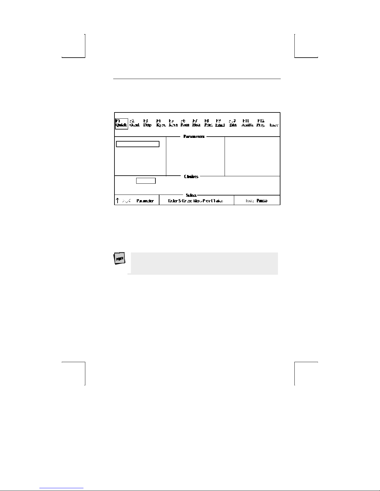
QUICK: F1
Prnt
Scrn
Emulation=Wyse-60
Aux Baud Rate = 9600
Aux Data Format = 8/1/N
Host/Printer = EIA/Para
Wyse-60
VT-200-7 VT-200-8
Comm Mode = Full Duplex
Enhanced = On
Language = U.S.
Wyse-50+
VT-100
PC-Term
EIA BaudR ate = 9600
EIA Data Forma t = 8/1/N
TVI 925 VT -300-7 VT-300-8ADD-VP
Emulation: [ADDS VP, Wyse 60, Wyse 50+, PC Term, TVI 925, VT300/8, VT300/7,
VT200/8, VT200/7, VT100]
Select the “personality” of the terminal (the way in which it
responds to commands). If you are using PC-Term emulation,
refer to the Local Leadin selection in the Keys: F5 section for
access to local “hot keys.”
All associated defaults are loaded when the emulation is
changed. Default choices are in bold. Some defaults may vary
depending on the selected emulation.
Comm Mode: [Full Duplex, Half Duplex, Full Block, Half Block]
Select the method of communication to match the host
computer.
EIA Baud Rate: [134,400, 115,200, 76800, 57,600, 38400, 19200, 9600, 4800, 2400,
2000, 1800, 1200, 600, 300, 150, 110]
Select the number of bits communicated per second to match the
speed at which the primary host or printer expects to
communicate.
Page 56

32 Setup
AUX Baud Rate: [38400, 19200, 9600, 4800, 2400, 2000, 1800, 1200, 600, 300, 150,
134.5, 110]
The speed at which the secondary host or printer expects to
communicate.
Page 57

QUICK: F1 33
Enhanced: [On, Off]
Normally, the terminal responds to a set of commands that
correspond to the emulation selected. When Enhanced mode is
on, the set of commands is extended to those printed in boldface
in the programming chapter.
EIA Data Format: [7/1/N, 7/1/O, 7/1/E, 7/1/M, 7/1/S, 7/2/N, 7/2/O, 7/2/E, 7/2/M, 7/2/S,
8/1/N, 8/1/O, 8/1/E, 8/1/M, 8/1/S, 8/2/N, 8/2/O, 8/2/E, 8/2/M, 8/2/S]
Select a data bits/stop bits/parity combination which matches
the data format of the primary host or printer. Parity
abbreviations are: O = odd, E = even, S = space, M = mark, and N
= none.
AUX Data Format: [7/1/O, 7/1/E, 7/1/M, 7/1/S, 7/2/N, 7/2/O, 7/2/E, 7/2/M, 7/2/S, 8/1/N,
8/1/O, 8/1/E, 8/1/M, 8/1/S, 8/2/N]
Select a data bits/parity bits/stop com bination which matches
the data format of the secondary host or printer. Parity
abbreviations are: O = odd, E = even, S = space, M = mark, and N
= none.
Language: [U.S., U.K., Danish, Finnish, French, German, Norwegian,
Portuguese, Spanish, Swedish, Dutch, Belgian-Flemish, Fr-Canadian, Italian, Latin
American, Swiss-French, Swiss-German, Turkish]
Select the language type which matches your keyboard’s layout.
Language: [U.S., U.K., Danish, Dutch, Finnish, Belgian-Flemish, French,
Fr-Canadian, German, Italian, Norwegian, Spanish, Swedish, Swiss-German,
Swiss-French, Turkish]
Select the language type which matches your keyboard’s layout.
Host/Printer: [EIA/Aux, EIA/Para, EIA/None, Aux/EIA, Aux/Para, Aux/None, None/EIA,
None/Aux, None/Para, None/None]
The first part of the selection indicates the host (either the EIA
port or the AUX port) and the second part of the selection
indicates the printer port (if a serial printer is used, either the EIA
or Aux port can be used to connect to the printer, but if a parallel
printer is being used, the PAR port should be used).
Page 58
34 Setup
GENERAL: F2
This chapter lists all possible parameters for each menu, and
all possible choices for each parameter. Depending on the
emulation selected, and the key mode (ASCII or ScanCode),
Setup will only present the valid set of parameters and choices
in each menu.
Emulation: Select the “personality” of the terminal. See the Quick
menu earlier in this chapter.
Enhanced: Choose whether the terminal can respond to
commands beyond the limitations of the current emulation. See
the Quick menu earlier in this chapter.
Auto Wrap: [On, Off]
Select whether the cursor drops to the next line when it reaches
the right margin or continues to display characters at the right
margin. In ANSI emulations, the default is off.
Auto Font Load: [On, Off]
Select whether the four font banks (0-3) should automatically be
loaded when screen size or the emulation is changed.
Auto Page: [On, Off]
When the cursor is moved off the page using a command that
includes scroll and Auto Page mode is on, the screen displays the
new page. These pages are numbered from 0 to a maximum of 9.
When on, Auto Page will track the page even if Auto Scroll is off.
The up-arrow key does not have a scroll command embedded, so
it cannot be used to view the previous page even when Auto Page
is on.
Auto Scroll: [On, Off]
Choose whether the terminal updates the display when the
cursor is moved beyond the boundaries of the currently viewed
screen.
Monitor Mode: [On, Off]
Page 59

GENERAL: F2 35
Choose whether control codes will be displayed as their graphic
representations or be acted upon as terminal/cursor commands.
Page 60
36 Setup
Screen Saver: [Off, 2 min, 5 min, 15 min, 30 min]
Select whether the screen will go blank after lack of activity from
the keyboard or the host of the selected period of time. The first
key typed at the keyboard when the screen is blank will
reactivate the display. The keycode will not be transmitted to the
host. The Caps Lock LED will flash while Screen Saver is active.
Use screen saver to prevent “phosphor burn” on the screen
when the display on the terminal is left unchanged for an
extended time period.
20 minutes after the screen saver is activated, Energy Star, a
power saving feature, is activated. The first key typed at the
keyboard brings the energy level back up.
Bell Volume: [0, 1, 2, 3, 4, 5, 6, 7, 8, 9]
Select the bell volume from off [0] to high [9]. This will be the
volume for alarm tones, warning bells, and keyclicks.
Warning Bell: [On, Off]
Select whether a warning bell is sounded when errors (such as
an invalid compose sequence) are encountered.
Host/Printer: Designates physical ports to the host and printer.
See the Quick menu earlier in this chapter.
Bell Length: [140 ms, 350 ms, 570 ms, 780 ms]
Denotes duration of bell sound.
Page 61

DISPLAY: F3
Page Length: [24, 25, 42, 43, 48, 50, 84, 86, 96, *24, *25, *42, *43]
Select the number of lines per page. As many as four pages (0-3)
may be available, but the number of pages in memory depends on
the number of lines per page and whether 80-Only is selected for
columns. The total lines used (Lines/Page x # of Pages) will not
exceed 96. See the Page Configurations in Appendix A.
Page lengths which are multiples of 24 or 25 and those that are
multiples of 42 or 43 are displayed by default on a 26-line or
44-line screen, respectively. The extra one or two lines on the
screen can be used as status lines.
If a page length which is preceded by an asterisk (*24, *25, *42, or
*43) is selected, the total number of pages will be two, where the
first page contains the number of lines in the selection (24,25,42,
or 43) and the second page contains the remaining allowable
lines. (See Appendix A.)
Screen Length: [26 Lines, 30 Lines, 44 Lines, 52 Lines]
Select the number of lines that can be displayed on the screen at
one time. The page length affects the default screen length.
Screen Video: [Normal, Reverse]
Choose between bright characters on a dark background (normal)
and dark characters on a bright background (reverse). In reverse
video mode only, the “Enhanced Attributes” parameter is
available (see page 3-8).
Display Cursor : [On, Off]
Choose whether the cursor will be displayed.
Cursor: [Blink Block, Steady Block, Blink Line, Steady Line]
Choose the appearance of the cursor.
Auto Adjust Cursor : [On, Off]
Select whether the screen attempts to follow the cursor down
the page by scrolling just enough to keep the cursor in view.
DISPLAY: F3 37
Page 62

38 Setup
Columns: [80, 132, 80-Only]
Choose the number of columns that the screen can display.
80-Only provides more pages in memory for a given page length by
disallowing changes to 132-column display.
Width Change Clear: [On, Off]
Select whether the screen is to be cleared when the number of
columns on the screen is changed from 80 to 132 or vice versa.
Changing columns from/to 80-only forces the screen to clear
independent of Width Change Clear.
Speed: [Fast, Normal]
Selecting “fast” improves the speed at which screen display
occurs at the expense of minor, temporary distortion of text
called “tearing.”
Scroll: [Jump, Smooth]
Choose whether the data on the screen scrolls smoothly or
“jumps” to accommodate data at the rate it is received.
Scroll Speed: [Smooth 1, Smooth 2, Smooth 4, Smooth 8]
Select the number of scan lines per second the page scrolls up
when smooth scroll is selected. Smooth 1 is the slowest rate and
Smooth 8 is the fastest.
Refresh Rate: [60 Hz, 71 Hz, 82 Hz, 100 Hz]
Select the rate (number of times per second) at which the image
on your terminal’s display is updated. This selection is only
available in 26 or 30 line display mode.
Overscan Borders: [On, Off]
Choose whether the overscan borders are active. The borders
extend video from one edge of the screen to the next. (To see
the borders, select reverse for Screen Video.)
Page 63
KEYBOARD: F4 39
KEYBOARD: F4
Language: [U.S., U.K., Danish, Finnish, French, German, Norwegian,
Portuguese, Spanish, Swedish, Dutch, Belgian-Flemish, Fr-Canadian, Italian, Latin
American, Swiss-French, Swiss-German, Turkish]
Select the language type which matches your keyboard’s layout.
Language: [U.S., U.K., Danish, Dutch, Finnish, Belgian-Flemish, French,
Fr-Canadian, German, Italian, Norwegian, Spanish, Swedish, Swiss-German,
Swiss-French, Turkish]
Select the language type which matches your keyboard’s layout.
Char Set Mode: [PC, ANSI, ASCII]
Choose which NRC set to use. This selection is only available in
National Mode and foreign languages. In VT emulations, the
default is ANSI. To determine which sets are loaded for each
mode, refer to the 260xx Programmer’s Reference Guide.
Key Mode: [ASCII, ScanCode]
Select whether keys transmit ASCII codes or the ScanCode. The
ScanCode transmits a “make code” when a key is pressed and a
“break code” upon its release. When ScanCode is selected,
“Comm Mode” is forced to Full Duplex and “Character Set” is
forced to Multinational (8-bit).
Keyclick: [On, Off]
Choose whether pressing a key results in a clicking sound.
Key Repeat: [On, Off]
Choose whether keys, including function keys, will repeat when
pressed for more than half a second. This setting does not affect
the following keys on the EPC keyboard: Caps Lock, Scroll Lock,
Num Lock, Shift keys, Ctrl keys, Alt keys, Return, Print Screen,
Pause. On the ANSI keyboard, the following keys are unaffected:
Lock, F1–F5, Shift keys, Control, Compose, and Return.
Key Rate: [15 cps, 20 cps, 30 cps]
When “Key Repeat” is on, a key that is pressed for more than half
a second will automatically repeat. This selection allows you to
Page 64

40 Setup
choose the number of characters that are generated per second
when a key is auto repeating.
Page 65

KEYBOARD: F4 41
Keyboard Layout: [Q, F]
This selection is only available when Turkish keyboard is
selected. Q and F refer to the two Turkish keyboard layouts
available. Q and F correspond to the top left key on the
alphanumeric keypad.
Margin Bell: [On, Off]
Choose whether a bell tone sounds when the cursor is nine
positions away from the right margin.
Key Lock: [Caps, Reverse, Shift]
Affects the state of alphanumeric keys when Caps-Lock is
engaged.
þ Caps causes alphabetic keys to be uppercase regardless of the
Shift key.
þ Reverse causes the Shift key to generate lowercase
alphabetic keys.
þ Shift causes all alphanumeric keys to be generated as
uppercase (or shifted, in the case of numbers). If the Shift key
is hit, while Shift is selected, Caps-Lock will be disengaged.
Caps Lock: [Toggle, Always On, Always Off]
This setting effects the state of the Caps Lock key. When set to
always on or always off the key has no effect. When set to toggle,
the terminal will power on in the off mode and pressing the key
will alternate between the off mode and the on mode.
Num Lock: [Toggle, Always On, Always Off]
This setting effects the state of the Num Lock key. When set to
always on or always off the key has no effect. When set to toggle,
the terminal will power on in the off mode and pressing the key
will alternate between the off mode and the on mode.
Code Page: [DEC Multi, CP 437, CP 850, CP 852, CP 857, CP 860, CP 861, CP 863,
ISO-1, ISO-2, ISO-5]
This selection is only available in 8-bit emulations in
Multinational Mode. The default code page is based upon
language and emulation selected. To determine which sets are
Page 66

42 Setup
loaded for each code page, refer to the 260xx Programmer’s
Reference Guide.
Page 67

KEYS: F5
Enter Key: [CR, CR-LF, TAB]
Select the code the enter key in the numeric keypad transmits.
Return Key: [CR, CR-LF, TAB]
Select the code the return key on the main alphanumeric keypad
transmits.
Alt Key (left): [Meta, Compose, Funct, Scroll-Lock, Alt Key]
Select the way in which the left ALT key (or the Compose key on
the ANSI keyboard) behaves.
þ Meta sets the most significant bit for the next character and
allows 8-bit data to be generated from the keyboard.
þ Compose precedes sequences of keys to create a character
that is not on the keyboard but is available in the active
character set.
þ Scroll Lock causes the Alt key to function as the Scroll Lock
key, and is a toggle to hold/free data on the screen. It
requires the use of flow control for the host port Rcv Prtcl.
þ Funct causes the Alt key to function as the Funct key on an
ASCII keyboard.
þ Alt Key causes the left Alt key to behave identically to the
right Alt key.
Pound Key: [U.S., British]
Choose the character transmitted for 23h—the US pound (#) or
the British pound (£).
Return Key Repeat: [On, Off]
Select whether the Return key located on the alphanumeric
keypad will repeat when held down for more than half a second
(only selectable when “Key Repeat” = On).
Local Leadin: [On, Off]
This parameter is only available when Key Mode (in the Kybd
menu) is ScanCode. If Local Leadin is off, the only local function,
shown in Appendix A, is Ctrl-Scroll Lock (Ctrl-Select on the ANSI
KEYS: F5 43
Page 68

44 Setup
keyboard) to enter Setup. If Local Leadin is on, the Setup
keystroke “introduces” the keystroke as local and then local
functions can be generated using the keystrokes listed in
Appendix A.
Page 69
KEYS: F5 45
For example, to enter Setup when ScanCode and Local Leadin
are on, press Ctrl-Scroll Lock (Ctrl-Select on the ANSI keyboard) to
introduce this as a local function (“LEAD” will appear in the
status line), and then Ctrl-Scroll Lock (Ctrl-Select on the ANSI
keyboard) to enter Setup.
Local Leadin will not work if Comm Mode is set to Half Block or
Full Block.
UDKs: [Emul Dependent, User Dependent]
Choose whether the UDKs should get defaulted when the host
changes the emulation.
The following selections apply to the PC keyboards:
Disconnect: [Disabled, Pause, Alt-Pause]
Sele ct the keystroke that will generate a modem disconnect.
Backspace: [BS/DEL, DEL/BS, DEL/CAN, BS/BS]
Choose the codes sent by the backspace key in the
normal/shifted positions.
Desk Acc: [Sh-Ctrl-Fkeys, Ctrl ←←, Disabled]
Select how the Desk Accessories can be accessed. This selection
does not appear when SCO Console emulation is selected. In
SCO Console emulation, Ctrl ← is the only access method.
The default allows the desk accessories to be accessed through a
menu which appears when Ctrl and the left arrow key are
pressed simultaneously. This brings up a pop -up window;
selections for the specific accessory can be made from that menu
by pressing F1-F5. The Sh-Ctrl-Fkeys option, when selected,
allows direct access to desk accessories (bypassing the menu) by
pressing Sh-Ctrl-F1 through Sh-Ctrl-F5. Selecting Disabled will
inhibit entry to desk accessories. Once a desk accessory is
displayed, any other desk accessory can be accessed by pressing
only the function key associated with it (without pressing
Sh-Ctrl).
Page 70

46 Setup
The following selections apply only to the ANSI keyboard:
Disconnect: [Disabled, Shift-F5]
Choose to allow the keystroke that will generate a modem
disconnect on the ANSI keyboard or to disable the Disconnect
function. Note that if “F1 to F5 keys” is Fkey in Setup, the
Disconnect function will be remapped to Ctrl-Shift-F5.
F1 to F5 keys: [Local, Fkey]
This selection determines whether the first five keys, labeled F1–
F5, serve as local keystrokes (for example, F3 allows access to
Setup) or will serve as function keys which are loaded with the
default strings. (Only reprogrammed strings are visible in the text
area for a given function or edit key; the default strings are not
visible in Setup.)
If Fkey is selected, then the keystroke to enter Setup becomes
Ctrl-F3 on the ANSI keyboard.
With the three remapping selections, keys which are available on
a PC keyboard are now available on a PC keyboard are now
available on the ANSI style keyboard: [ESC] [`~] [, and .].
The three selections
should either be kept in
their defaults (as they
appear on the keyboard),
or all three should be
changed to follow the
mapping scheme
described here.
,, and .. [,, and .. or ,< and .>]
Select the character sent by the comma and period keys in the
normal and shifted mode.
<> Key [< and > or ` and ~]
Select the characters sent by the triangle bracket key in the
normal and shifted positions.
Page 71

/~ Key [` and ` or ESC]
Select the characters sent by the tic/tilde key.
Backspace: [BS/DEL, DEL/BS, DEL/CAN]
Choose the codes sent by the key in the normal/shifted
positions.
KEYS: F5 47
Page 72

48 Setup
PORTS: F6
EIA Baud Rate: [134400, 115200, 76800, 57600, 38400, 19200, 9600, 4800, 2400,
2000, 1800, 1200, 600, 300, 150, 110]
See the Quick menu earlier in this chapter.
EIA Data Format: [7/1/N, 7/1/O, 7/1/E, 7/1/M, 7/1/S, 7/2/N, 7/2/O, 7/2/E, 7/2/M, 7/2/S,
8/1/N, 8/1/O, 8/1/E, 8/1/M, 8/1/S, 8/2/M, 8/2/N, 8/2/O, 8/2/E, 8/2/S]
See the Quick menu earlier in this chapter.
EIA (Aux) Parity Check: [On, Off]
Choose whether the parity bit will be checked. When parity
check is on and the parity bit received is inconsistent with the
data received, indicating an error in communications, an asterisk
(*) 2Ah is displayed instead of the character.
Aux Baud Rate: [38400, 19200, 9600, 4800, 2400, 2000, 1800, 1200, 600, 300, 150,
134.5, 110]
See the Quick menu earlier in this chapter.
AUX Data Format: [7/1/O, 7/1/E, 7/1/M, 7/1/S, 7/2/N, 7/2/O, 7/2/E, 7/2/M, 7/2/S, 8/1/N,
8/1/O, 8/1/E, 8/1/M, 8/1/S, 8/2/N]
See the Quick menu earlier in this chapter.
EIA (Aux) Recv: [No Protocol Xon-Xoff (XPC), Xany-Xoff (XPC), DTR (DSR),
Xany-Xoff/DTR (DSR)]
Choose the form of flow control for data received from the primary
or secondary host. Software flow control uses Xon-Xoff DC1 (11h)
and DC3 (13h). XPC is used by “Scan Code” mode because it uses
DC1 and DC3 as data. Xany-Xoff (XPC) is similar to Xon-Xoff,
except that any character transmitted to the host is treated as an
Xon, so data from the terminal is buffered, rather than being sent
to the host. DTR (DSR for Aux) relies on the hardware signal DTR
or DSR (pin 20 or pin 6) from the device. Xany-Xoff/DTR (DSR)
uses software and hardware flow control.
Flow control is recommended to protect against data loss.
Page 73

PORTS: F6 49
EIA (Aux) Xmit: [No Protocol, Xon-Xoff, DSR (DTR), Both]
This is similar to “EIA (Aux) Recv,” except that it applies to the
data transmitted from the terminal to the primary or secondary
host or printer. DSR is the hardware signal for Data Set Ready
(pin 6).
In ADDS VP emulation, DC1 and DC3 can be interpreted as
data and should not be selected as a form of protocol.
EIA (Aux) Break: [250 ms, 170 ms, 500 ms, Off]
Choose the duration of the break signal in milliseconds. This is
an interruption in data flow, and can be disabled.
EIA (Aux) Modem Control: [On, Off]
If a modem is being used to communicate with the primary or
secondary host, modem control should be on. To perform a
disconnect, the terminal drops the DTR signal. In full duplex, the
terminal keeps RTS high and checks for a CD signal before
sending data to the modem. In half duplex, it raises RTS and
awaits a clear -to-send (CTS) signal from the modem before
sending data.
EIA (Aux) Xmt Pace: [Baud, 35 cps, 60 cps, 150 cps]
Define the maximum number of characters per second that the
terminal can transmit. When a characters limit (35 cps, 60 cps, or
135 cps) is set, the delays are averaged between characters for
the selected baud rate. This is also known as “pacing.” The
Baud option provides no pacing, allowing data to be transmitted
at the specified baud rate.
EIA (Aux) Disconnect: [2sec, 60ms]
Select the maximum time period that the modem can be
disconnected (or the modem line be down) before the terminal
performs a Modem Disconnect. This occurs if “EIA (Aux) Modem
Control” is on.
Page 74

50 Setup
HOST: F7
Comm Mode: [Full Duplex, Half Duplex, Full Block, Half Block]
Select the communications mode.
Half-duplex is not available when KeyMode is ScanCode.
Receive <CR>: [<CR>, <CR><LF>]
Select the way in which carriag e returns received will be
interpreted.
Receive <DEL>: [Ignore, Destruct <BS>]
Choose to ignore the DEL control code (7Fh) when received or to
treat it as a Destructive Backspace code.
Send ACK: [Off, On ]
Decide whether the terminal should respond to inquiry (05h) or
when certain terminal functions are performed (configuring the EIA
(Aux) ports, splitting screen, etc.) with the ACK (06h) character.
Null Suppress: [On, Off]
In the default mode, the host ignores all received nulls (00 hex).
When off is selected, the terminal will accept all received nulls,
and act upon them according to the selected emulation.
Send Line Term: [<US>, <CR><LF>]
Select which line terminator is sent. <US> is 1Fh and <CR><LF>
is 0Dh 0Ah.
Local: [Off, On]
Select whether keyed data is interpreted locally by the terminal
and not sent to the host. Data sent by the host is lost, if Local is
on. The ability to print data is not affected by this mode.
Send Block Term: [<ETX>, <CR>]
Select which character will indicate the end of a block. The
choices above are for ASCII emulations. ANSI emulations have
the following choices: [None, FF].
Send End: [Cursor, Region]
Page 75

HOST: F7 51
Select whether the end is indicated by the scroll region or by the
cursor location.
Send Region: [Screen, Scroll]
Choose whether the terminal sends data from the entire screen
or from the scrolling region.
Page 76

52 Setup
PRINT: F8
Print Mode: [Normal, Auto, Controller]
Select the way in which printing is controlled.
þ Normal indicates that printing is to occur when a print
request (such as print screen) is received.
þ Auto prints a line when the terminal receives a LF, a FF, or a
VT code, or when autowrap occurs.
þ Controller indicates that host data is sent to the printer
(pass through mode). Printing is controlled by the host
computer.
Print Block Term: [<ETX>, <CR>]
Select the character which indicates to the printer that the block
of data to be printed has ended. The options above are for ASCII
emulations. In ANSI emulations, the choices are [None, <FF>].
Print Region: [Screen, Scroll]
Indicate the region of the screen that is to be printed: the entire
screen or a certain section of it called the scrolling region. A
scrolling region is a limited portion of the screen which
applications (such as word processors) may designate to be the
user’s.
Print Line Term: [<US>, <CR><LF>]
Indicate the character that <R>is to terminate a line of print.
Secondary Recv: [Off, On]
When “on,” data received from the serial printer is routed to the
port assigned for the host. This data is not displayed on the
screen, and is transparent to the user. When “off,” data received
from the printer port is ignored.
Page 77

EMULATION: F9 53
EMULATION: F9
The parameters displayed in this menu depend upon the current
emulation. This section is divided between parameters for ASCII
and ANSI emulations.
ASCII Emulations
Page Edit: [Off, On]
When page edit is on, edit features such as insert act upon text
to the end of the current page.
WPRT Intensity: [Dim, Normal, Suppress]
Choose the intensity of write protected characters . Suppress
indicates that the character’s foreground is the same as its
background with the effect of “suppressing” output.
WPRT Underline: [Off, On]
Choose whether write-protected characters are underlined.
WPRT Blink: [Off, On]
Choose whether write-protected characters blink.
WPRT Reverse: [Off, On]
Choose whether write-protected characters display in reverse
video.
Fkey Speed: [Fast, Normal]
Selects the speed at which function keys and labels are
programmed by the host. Fast mode will increase the speed for
Wyse 50 compatibility, but will limit the amount of space in each
function key and answerback message to 8 bytes. Edit keys are
not available for programming in fast mode. Changing this
selection will default all function keys, edit keys, and function
keys labels.
Save Labels: [Off, On]
When on, labels that are downloaded by the host will be saved in
non-volatile memory. If this selection and Display NV Labels are
off, labels written by the host would be lost upon entry and exit
to Setup.
Page 78

54 Setup
Attribute: [Char, Line, Page]
Choose the extent to which attributes are propagated. (The only
parallel ASCII emulations are PC Term and Wyse 60.)
Page 79

EMULATION: F9 55
Display NV Labels: [On, Off]
Select whether the labels in non-volatile memory are displayed
on the lowest line. When off is selected, any existing labels will
remain on the screen, until on is selected, and they are
re-displayed. On a 26-line screen, they are displayed below line
24. On a 44-line screen, labels are displayed below line 42, and
on a 52-line screen, they are displayed below line 50. (The top
line is the top status line and cannot be used for data.) If the
page length used is a multiple of 25 (instead of 24) and the
screen length is 26 lines , then the last data line is used for data
and labels will not be displayed regardless of this setting. The
same is true for a page length that is a multiple of 43 (instead of
42) with a screen length of 44 lines.
Status Line: [Standard, Extended, Off]
Select the type of the status line. In standard, cursor row and
column, emulation indicator, print indicator, Caps Lock, and
communications mode are displayed. In extended, only emulation
indicator, Caps Lock, communications mode, protect and write
protect are displayed.
Char Set: [National, Multinational]
Select whether the character set used is the 7-bit national chart
or the 8-bit multinational chart when Language is not U.S. If U.S.
is chosen, the character set is multinational.
Enhanced Attributes: [Off, On]
When set to on, gives a better display presentation in overscan
and reverse video modes. The blink and dim video attributes will
affect the foreground text instead of the background. This
selection is only available in reverse video mode.
Bright Video: [Off, On]
Provides a brighter display when set to on. Both normal and dim
text are brighter than in the standard mode.
Page 80

56 Setup
ANSI Emulations
Numeric Kpd: [Numeric, Application]
Choose the set of strings sent by the numeric keypad.
Cursor Kpd: [Cursor , Application]
Choose the set of strings sent by the cursor control keypad.
Send Data: [All, Erasable]
Choose whether the data sent to the host is all data (erasable
and selectively erasable) or only those characters tagged as
erasable.
Print: [National, Line Drawing, Multinational]
Choose the set of characters used when printing.
ANSI-ID: [VT100, VT101, VT102, VT220, VT320]
Select the terminal’s identification.
Function Key Lock: [Off, On]
Select whether the function keys are loc ked or modifiable by the
host.
Key Usage: [Typewriter, Data Process]
This selection is available for all language selections except U.S.
It applies to keys that have two characters printed side-by-side to
select which character is sent by that key. Typewriter selects the
character printed on the left side while Data Process selects the
character printed on the right side of the keycap.
Char Set: [Multinational, National]
Select whether the character set used is from the 7-bit national
chart or the 8-bit multinational chart. The default is the 8-bit
multinational character set except when the emulation is VT100.
Feature Lock: [Off, On]
When on, the host cannot change user features: key repeat,
scroll speed, screen background, tab stops, and keyboard lock.
Status Line: [Off, Indicator, Host-Write, Both]
Page 81
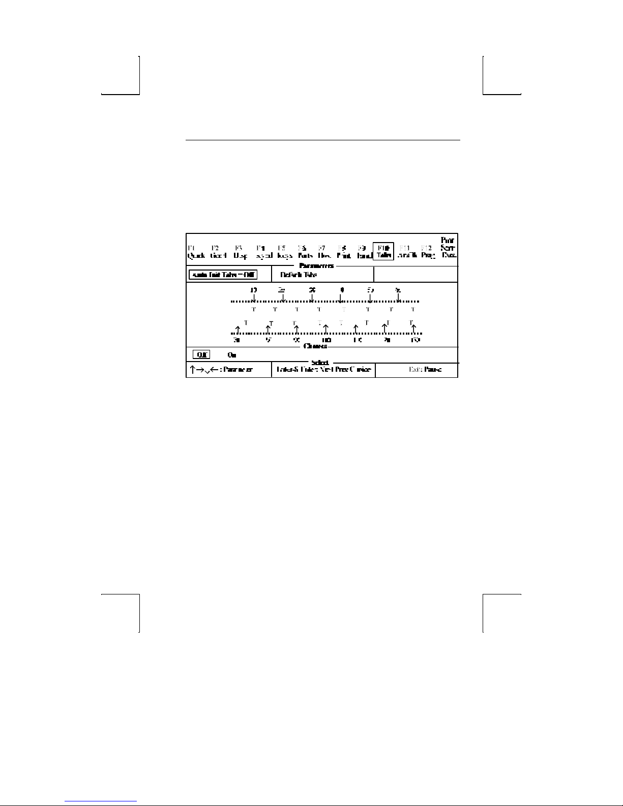
Specify the way in which the status line is to be used: for host
messages [host-write], as a cursor position indicator [indicator],
for [both] or off.
TABS: F10
Auto Init Tabs: [On, Off]
When on, tab settings will always be defaulted at power up.
Default Tabs: This action field sets tabs at every eighth column
starting at column 9.
When the cursor is placed in the Tab Map, the keys below will
appear in the Choices field:
þ <Space> – clear the current tab setting.
þ <Shift> <Backspace> – clear all tab settings.
þ <T or t> – set a tab at the current location.
þ < ↑↑ →→ ↓↓ ←← > – move cursor on the Tab map or back to a
Parameter field above the map.
TABS: F10 57
Page 82
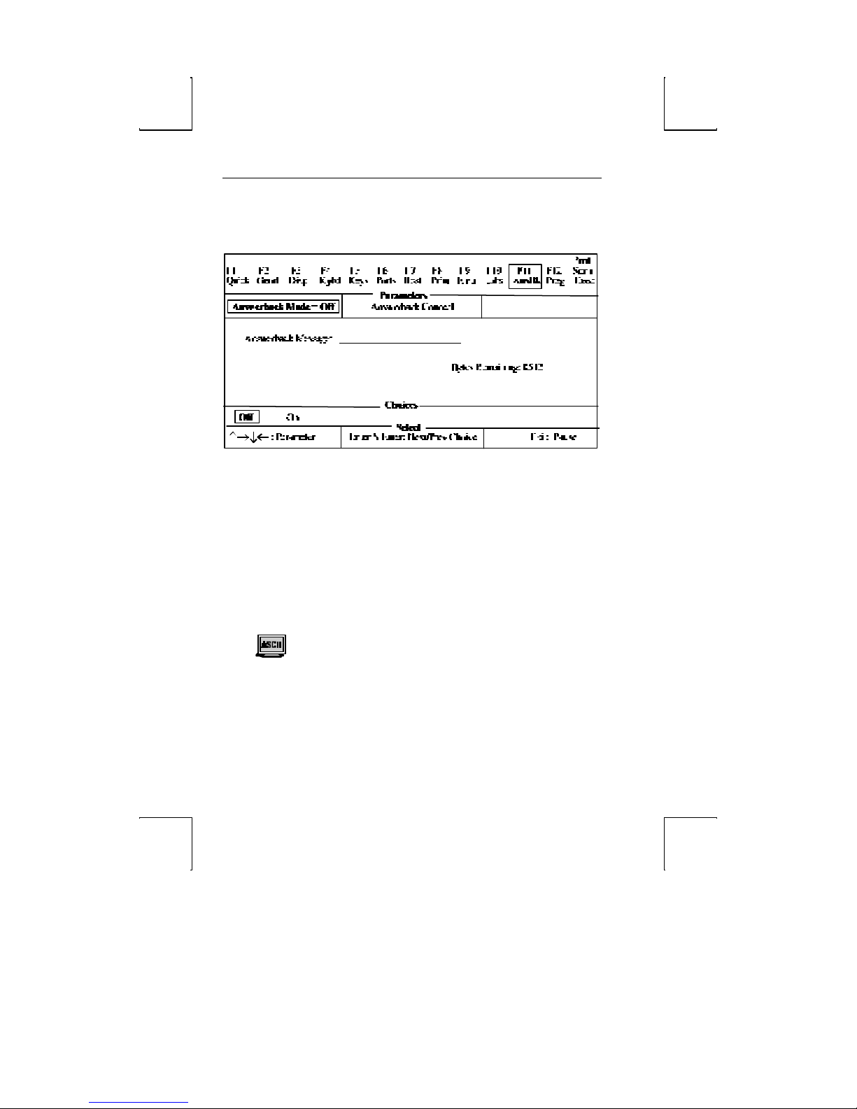
58 Setup
ANSWERBACK: F11
Answerback Mode: [On, Off]
Choose whether the answerback message (which is sent to the
host at terminal reset or power up) mode is on. This can be used
to log -in to the system.
Answerback Conceal: This is an action parameter which displays
“Concealed” at the answerback edit field. Once it is concealed,
the message cannot be redisplayed. This is a security measure
for those who use answerback to send their login names and
passwords to the host.
Answerback Message: This is a 30-character field which can be
edited. (See the Edit Fields section later in this chapter.)
When “Fkey Speed” is Fast in the Emul (F9) menu, the
answerback edit field is limited to 8 bytes.
Page 83
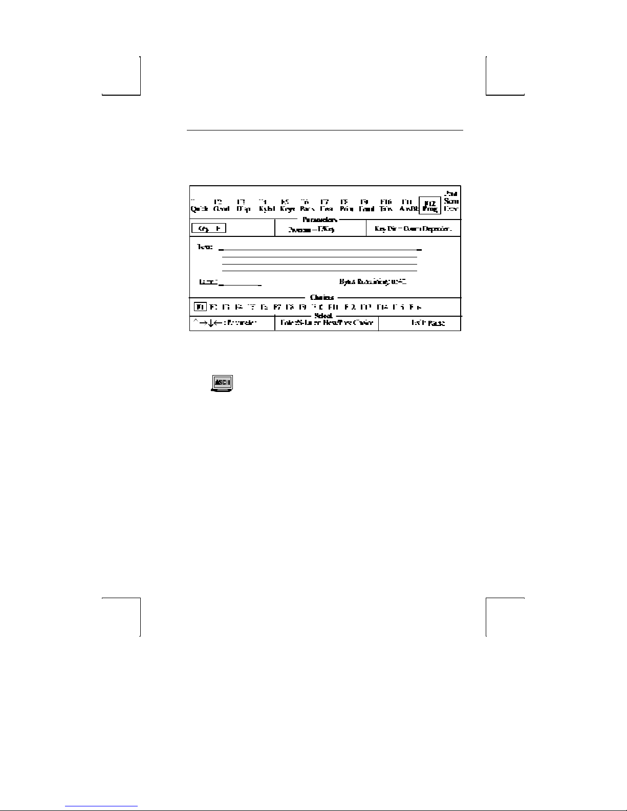
PROGRAM: F12 59
PROGRAM: F12
Program: [F/Key, Sh-F/Key, Edit Key, Sh-Edit Key]
Specify the type of key to be programmed —function or edit key in
its normal or shifted state.
When Fkey Speed is Fast in the EMUL (F9) menu, the
Program options are F/Key and Sh-F/Key.
Key Dir: [Comm Depend, Host, Printer, Printer & Host, Screen, Host & Screen, Printer &
Screen, All]
Select the destination of the contents of the function or edit key.
Comm Dependent will cause the direction of the key data to
correspond to the “Comm Mode” of the current emulation. For
example, if the “Comm Mode” is Full Block, the contents of the
key will be channeled to the screen only. If it were Full Duplex,
then the contents would be sent to the host only.
Text: An edit field which permits up to 255 characters. Once the
overall text limit (up to 542 characters) is reached, the terminal
will beep and accept no more text. If the text is deleted with the
backspace key, the default code is no longer programmed.
Page 84

60 Setup
Shift-Backspace will restore the default. See the Edit Fields
section or “Fkey Speed” in the Emulation section.
Page 85
PROGRAM: F12 61
Label: A label of up to 7 characters can be entered for function
keys in ASCII emulations only. See “Display NV Labels” in the
Emulation section.
þ <Backspace> – delete
þ <Shift> <Back> – default field
Key: Select the key to be programmed. The keys that are listed as
choices depend upon the Program par ameter as shown below:
þ When Program = F/Key or Sh-F/Key, the choices are
[F1, F2, F3, F4, F5, F6, F7, F8, F9, F10, F11, F12].
þ When Program = Edit Key or Sh-Edit Key, the choices are
[Tab, Esc, Backspace, Delete, Return, Home, ↑, ↓, ←, →, EnterKpd, Insert,
PageDown, PageUp, End, and Print].
When a PC style keyboard is attached, the following choices
apply:
þ When Program = F/Key or Sh-F/Key, the choices are [F1, F2, F3,
F4, F5, F6, F7, F8, F9, F10, F11, F12].
þ When Program = Edit Key or Sh-Edit Key, the choices are [{Tab,
<X], Select, Return, ↑, ↓, ←, →, Enter, Next, Screen, Remove, PF1, PF2, PF3,
PF4].].
When an ANSI keyboard is attached, the choices are as
follows:
þ When Program = F/Key or Sh-F/Key, the choices are [F1, F2, F3,
F4, F5, F6, F7, F8, F9, F10, F11, F12, F13, F14, Help, Do, F17, F18, F19, F20]].
þ When Program = Edit Key or Sh-Edit key, the choices are [Home,
Esc, Backspace, Delete, Return, Home, ↑, ↓, ←, →, EnterKpd, Insert, PageDown,
PageUp, End, and Print].
þ To program an ESC (escape) character into the key text,
press Ctrl-[.
þ To program a DEL character into the text field, press
Ctrl-Shift-* (alphanumeric keypad).
þ To program a carriage return or line feed into the key text
Page 86

62 Setup
field, press Ctrl-M or Ctrl-J, respectively.
þ To program the “Print Screen” key to perform a local print
screen (page) function: In the key text field, press Ctrl-[ and
then P. Next, set the “Key Dir”=Screen option.
Page 87

EXECUTE: Prnt Scrn 63
EXECUTE: Prnt Scrn
All of the parameters in this menu are action parameters.
Terminal parameters affect all settings, including the emulation.
Emulation choices affect only settings that relate to the chosen
emulation.
Save Terminal: Save all settings in non-volatile (permanent)
memory, including those associated with the emulation selected.
Reset Terminal: All terminal parameters are initialized. It also
performs reset pages and default modes.
Recall Terminal: Revert to all terminal and emulation settings that
were saved in nonvolatile memory. A “Reset Terminal” is also
performed. This is referred to as a hard reset and is equivalent to
turning the terminal off and back on.
Default Terminal: Load all defaults for the terminal and emulation,
including the emulation. A “Reset Terminal” is also performed.
Save Emulation: Save all the settings associated with the chosen
emulation.
Reset Emulation: Initialize all emulation settings. This is also
referred to as a “Soft-Reset.” Perform page-resets and default
modes. “Mode” specifies the parameters used by a emulation
which are not selectable through Setup such as Insert-Mode,
Split-Screen, and Graphics-Mode.
Recall Emulation: Load the previously saved settings associated with
the chosen emulation. A “Reset Emulation” is also performed.
Default Emulation: Load all defaults associated with the emulation
selected.
Reset Ports: Clear the transmit buffers for the host and printer
port, and receive buffer for the host port. Unlocks the keyboard
and clears its buffer data.
Clear Screen: Clear the screen and the entire page.
Default Emulation UDKS: Set the contents of all the function and edit
keys associated with the chosen emulation to their factory
default states.
Page 88

64 Setup
Edit Fields
Setup uses overwrite mode in text editing fields. That is, the
cursor keys cannot be used to move to a location in the text to
insert characters. Upon entry to a text field, the cursor is placed
at the last text location. Use the following keystrokes:
þ Backspace – move cursor left by deleting that character.
þ Shift-Backspace – reset the field to its default value.
þ Alphanumeric keys – enter text in the normal, shifted, or
control state. To generate a control character (00h-1Fh) add
40h and use Ctrl with the character in the new position
(40h-5Fh). For example, to insert CR-LF (0Dh, 0Ah) codes,
press Ctrl-M, Ctrl-J (4Dh, 4Ah). The compose and meta
functions can also be used to generate 8-bit characters.
Glossary of Terms
Some of the terms that are used in the Exec (PrtSc) menu are
defined below.
Terminal Parameters
Terminal parameters includes emulation parameters (defined
later) and non-emulation parameters that affect the terminal
globally without regard to the emulation. The non-emulation
parameters and their defaults are listed below:
þ Setup Parameters: Bell Volume (6), Screen Saver (5 min),
Overscan Borders (on), Language (U.S.), Keyclick (on),
EIA(Aux) Baud Rate (9600), EIA (Aux) Data Format (8/1/N), EIA
(Aux) Parity Check (off), EIA(Aux) Rcv Prtcl (Xon-Xoff/XPC), EIA
(Aux) Xmit Prtcl (none), EIA (Aux) Break (250 ms), EIA (Aux)
Xmit Pace (baud), EIA (Aux) Disconnect (2 sec), EIA (Aux)
Modem Control (off), Emulation Display (full), Refresh Rate (70
Hz), Bright Video (off), Enhanced Attributes (on), Caps Lock
(Toggle), Num Lock (Toggle), Key Repeat (On), Speed (fast).
þ Desk Accessory Parameters: Clock Display (off), Clock Type (12
hour), Clock Location (column 48), Date, Time (not saved) ,
Page 89

Glossary of Terms 65
Alarm Time (12 PM), Tone (alarm/hourly), Calculator (printer
off, tape on), and the row and column in which each accessory
is displayed.
Emulation Parameters
Emulation Parameters are parameters that are specific to the
emulation selected. These include three types of parameters:
Setup-Edit keys, Setup, and Modes.
þ Setup-Edit Keys: Function and Edit keys and the Answerback
message.
þ Setup Parameters: All other Setup variables that are not included
in Setup Parameters in Terminal Parameters (all global
settings).
þ Mode Parameters: Variables that are used by a emulation’s
emulation, but are not selectable through Setup. Some
examples are Protect Mode, Graphics Mode, Insert Mode, Aux
Mode, Split-Screen, Transparent Mode, and Character Set
mappings.
Page Reset
Page resets are executed when the emulation or terminal is reset
or defaulted. When a page reset is performed, it affects all pages,
and the following events occur: the page is erased, the cursor is
homed, and scrolling regions are defaulted. All line attributes
(such as double-high/wide, locked lines) are reset to normal.
Split screens are cleared to a normal, single screen and protect
mode is turned off.
Page 90
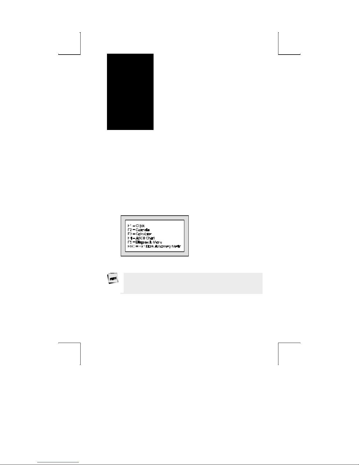
chapter
4
Desk Accessories
This terminal features five desk accessories, which can be
accessed one at a time through pop -up windows.
Overview
Desk Accessory Menu
To display this pop -up window to choose any of the five desk
accessories, press Ctrl- ←.
Function keys F1-F5 are used to display the clock, calendar,
calculator, ASCII chart, and diagnostic menu, respectively.
To access this menu (with a PC keyboard), the selection
“Desk Acc = ←” must be chosen in the KEYS (F5) Setup menu.
This menu is always available with the ANSI keyboard.
55
Page 91
56 Desk Accessories
Direct Access
To display any desk accessory directly, without the desk accessory
menu, the following keystrokes are used:
þ Clock – press Ctrl-Shift-F1
þ Calendar – press Ctrl-Shift-F2
þ Calculator – press Ctrl-Shift-F3
þ ASCII Chart – press Ctrl-Shift-F4
þ Diagnostic Menu – press Ctrl-Shift-F5
You may also use a function key (F1-F5) to enter another desk
accessory window, once one is entered.
To use these keystrokes with a PC keyboard, the selection
“Desk Acc = Sh-Ctrl-Fkeys” should be chosen in the KEYS (F5)
Setup menu. If an ANSI keyboard is attached, the “F1 to F5
keys = Local” should be chosen in the KEYS (F5)Setup menu.
To reposition any window on your screen, hold down the Shift
key while pressing a cursor control (arrow) key.
Exit Keystrokes
To exit any window and restore the original screen:
Press ESC on the PC keyboards
Press F11 on the ANSI keyboard
Inhibiting Access
Access to desk accessories can be inhibited by selecting
“Disabled” for “Desk Acc” in the Setup menu.
Page 92
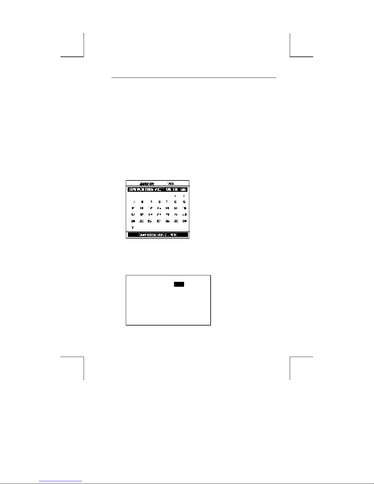
Calendar
Jan.
This displays a calendar for any month from the years 1900 to
2099. The current date is displayed at the bottom. The keys
below control the calendar that is displayed:
þ Right- and left-arrow keys – display an earlier or later
month.
þ Up- and down-arrow keys – display the selected month in an
earlier or later year.
þ Esc – exit calendar.
The specified calendar month will display as shown below:
Calendar 57
Clock
The clock menu (shown below) contains seven lines which can
be modified:
Date 1, 1995
Time 08:00:00 AM
Display Off
Type 12
Column 48
Alarm Set 12:00 PM
Tone Off
Page 93

58 Desk Accessories
Use the following keys to make changes:
þ Up- or down-arrow keys – select a line. The line is
highlighted.
þ Left- or right-arrow keys – select a field on the chosen line.
The selected field is now highlighted.
þ Spacebar – move “up” through options available for this
field.
þ Shift-Spacebar – move “down” the options.
þ Enter (num) – revert to the default setting for the current
field.
þ Esc – exit clock and save settings.
Each of the seven fields is described below:
The clock is reset to 08:00 AM at power -up. Due to hardware
limitations, the clock may drift by 15 seconds per day. We
recommend setting the terminal’s time as part of the system
login process.
Date – use the left or right arrow keys to highlight each field of
the date (month, day, and year). Then, use the Spacebar or press
Shift-Spacebar to cycle through the settings. The date can also
be set by the host.
Time – use the procedure described for Date above to set the
hour, minutes, or seconds.
Display – indicate whether only Time, only Date, or both the
Time and the Date are displayed on the top status line. Display
of Time/Date can also be turned Off. The date display can also
be set by the host.
Type – select whether the clock functions on a 12- or 24-hour
basis.
Column – set the column (36–99) in which the date/time will
display (as enabled by Display above).
Alarm Set – time at which an alarm (a 1–2 second bell tone)
should sound.
Page 94

Clock 59
Tone – how alarm tone(s) should be activated: every Hour, on the
Alarm setting only, or both on the Alarm setting and Hourly. The
alarm tone can also be turned Off.
Page 95

Calculator
The numeric keypad located on the right side of your keyboard
will serve as your calculator. See the figures below to relate the
display to the keys on the numeric keypad that control it.
The ANSI keyboard calculator display is identical to the ones
shown below for the PC keyboard except that the controlling keys
on the numeric keypad are different. The ANSI keyboard control
keys include PF1-PF4 keys and funciton keys F16-F20.
The calculator can process up to 10 digits to the left of the
decimal point, and up to 9 to the right. When a number or
number operator is pressed, it is momentarily highlighted on the
display.
Number operators are defined as follows:
þ +, -, /, X – the respective operations of addition, subtraction,
division, and multiplication.
þ MS – stores the displayed value in memory.
þ MR – displays the stored value
þ M+ – adds the displayed value to memory.
þ +/- – make a number positive/negative.
þ C/A – displays 0.0 when pressed once. When pressed twice,
clears memory.
The figures below represents the calculator display:
Calculator 60
Page 96
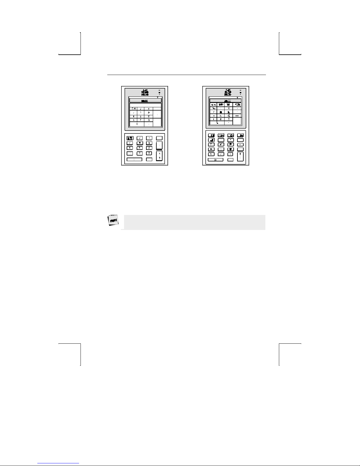
ASCII Chart 57
Calculator Display (EPC keyboard)
Calculator Display (PC/+
keyboard)
In addition to the keys on the numeric keypad, you may use:
þ T – toggle “tape” on/off. Results scroll above the display.
þ P – toggle “printer” on/off. Results are transmitted onto the
printer.
Use the printer option only when a printer is connected. Press
Ctrl-Shift-Tab to clear a printer error.
þ X – exit the calculator, transmitting the final result to the
current application.
þ Ctrl – (a number on the numeric keypad) - specify the
precision, where the number of decimal places that will be
displayed is equal to the number pressed with the Ctrl key.
þ Esc – exit calculator.
ASCII Chart
The ASCII chart, upon entry to this desk accessory, is centered
on the character on which your cursor was last placed, and that
character is highlighted. The chart will display as shown below:
Page 97
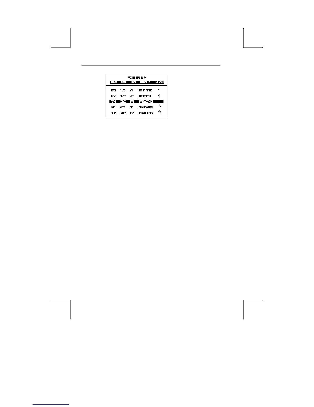
ASCII Chart 61
Characters are also displayed in octal, hexadecimal, and binary
number representations. The CHAR column contains the ASCII
representation of the character.
Page 98
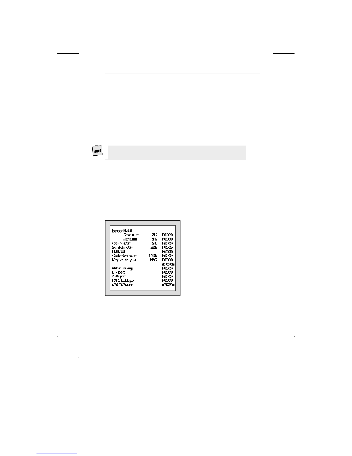
62 Desk Accessories
Use the following keys to change the display of the ASCII chart:
þ Up- or down-arrow – scroll up or down the characters in the
ASCII chart (0-127).
þ Left- or right-arrow – scroll through the available font banks.
The characters will display from the selected font bank.
þ Ctrl- ↑↑ ,Ctrl-→→ , Ctrl-↓↓ , Ctrl-←← – move the cursor on the
screen up, right, down, or left. The ASCII chart will be
redisplayed, and the chart will be centered on the character
that the cursor now rests upon.
Upon exit, the cursor will be restored to its previous location at
the time of entry to the desk accessory(ies).
þ Esc - exit the ASCII chart.
Diagnostic Menu
This desk accessory is used to display terminal configuration
information such as the amount of memory (RAM) in the
terminal, the style of keyboard that you are using, and the
firmware revision level. An example of the diagnostic menu is
shown below:
If you require technical support, this menu provides a means for
our support team to quickly assess your terminal installed
options.
Page 99

Diagnostic Menu 63
Note:
This page i s
inten tio nally
left blank .
Page 100
A
Appendix
Local Keys
Action
Toggle Caps -Lock No Lock Lock
Toggle Num -Lock No Num-Lock
Toggle Scroll-Lock1 No Scroll-Lock F1
Toggle Auto Print2 Yes Ctrl-Print-Screen Ctrl-F2*
Toggle Block-Mode Yes Ctrl-Shift-Pause F4*
Toggle Monitor Mode Yes Ctrl-Shift-1\End Ctrl-Shift-1 (num)
Toggle Ins/Replace No Ctrl-Insert Ctrl-PF4
Instant Screen Saver3 Yes Ctrl-Shift-* Ctrl-Shift-PF3
Soft Reset4 No Shift-Scroll Lock Shift-F3*
Hard Reset (Power On) No Ctrl-Shift-Scroll
Break5 Yes Ctrl-Pause F5*
Modem-Disconnect6 No Pause Shift-F5*
Send-Answerback No Shift-Pause Ctrl- F5*
Print-Page Yes Ctrl-Shift-Del\. Ctrl-Shift-. (num)
Scan
Code
Mode
PC Keyboard
Lock
ANSI Keyboard
Ctrl- F3*
Continued
63
 Loading...