

Page 1
Sumo
Assembly
Instructions
Page 2

Contents
In the Box
Tools Required
Configuration Options
Configuration A
Configuration B
A1
B1
A20
B19
Page 3
1
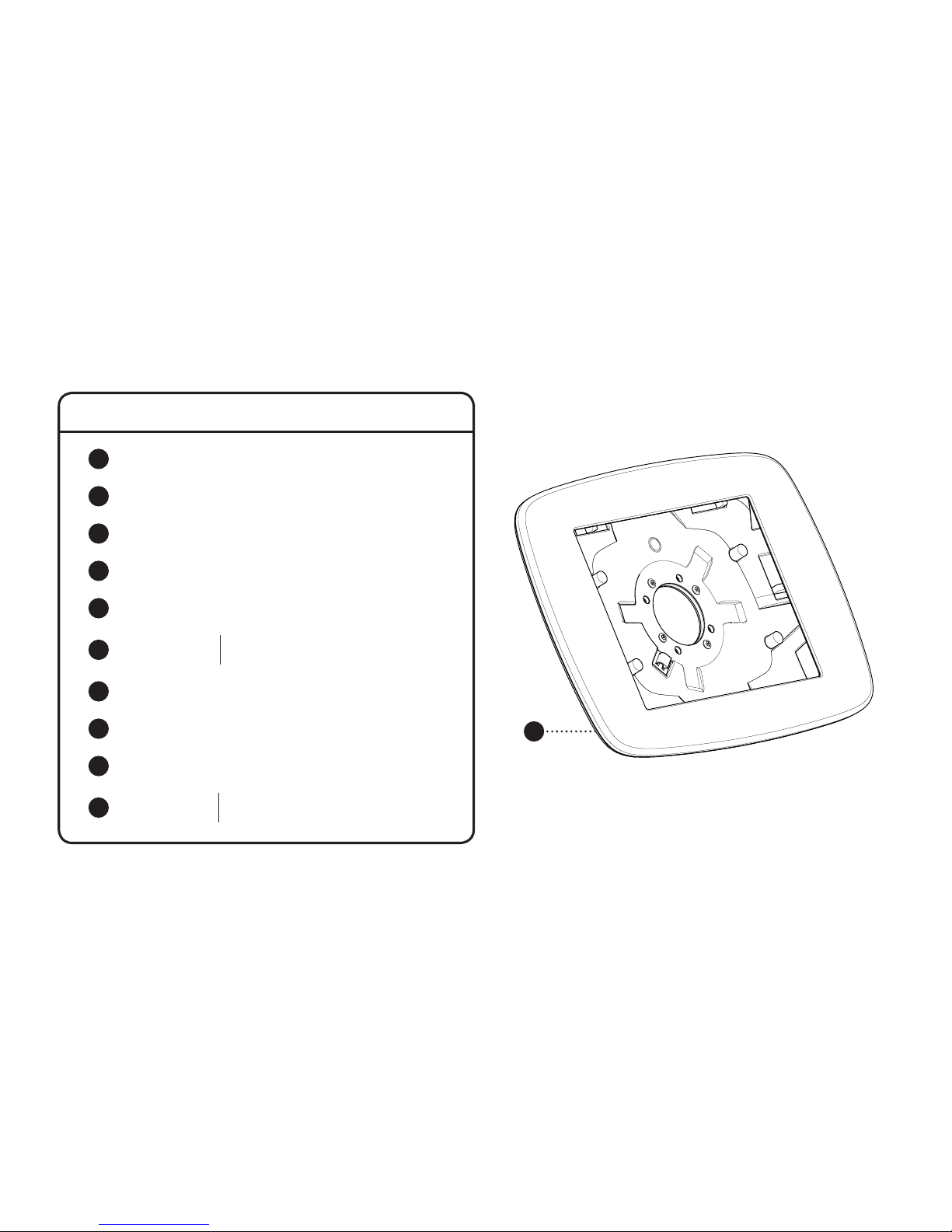
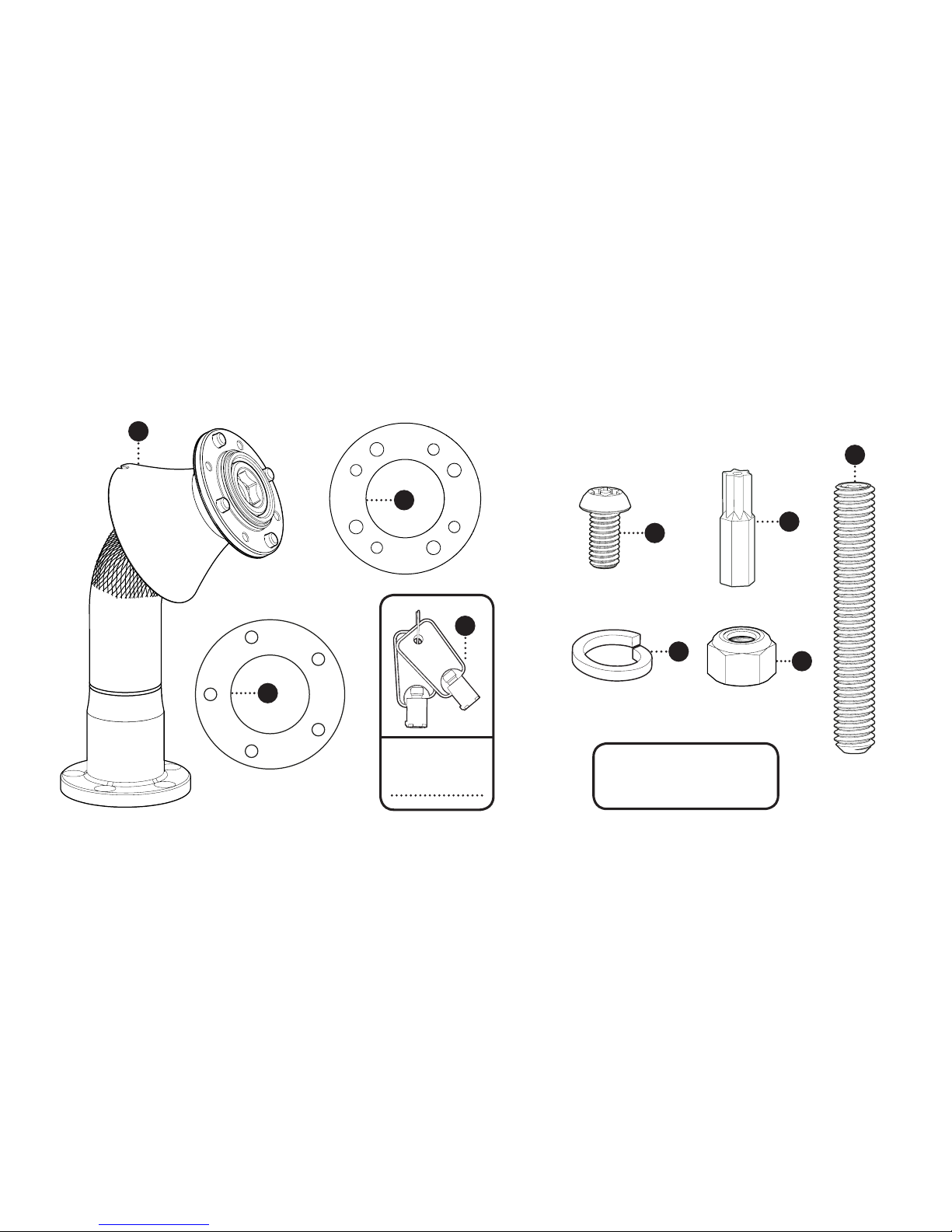
In the Box
1
Sumo Case
2
Sumo Stalk
4
Case Clamping Plate
3
Surface Clamping Plate
5
Case Keys x2
8
T30 Security Driver Bit
10
M6 x
40mm
1 5/8”
Socket Set-screw x5
9
Nyloc Nuts x5M6
7
M6 Split Washers x5
6
M6 x
12mm
15/32”
Button-head Security Screw x4
Page 4
7
10
6
9
Need advice if you’re
using custom fixings?
Give us a call.
8
2
4
3
5
Key Number
Page 5
A D E F G
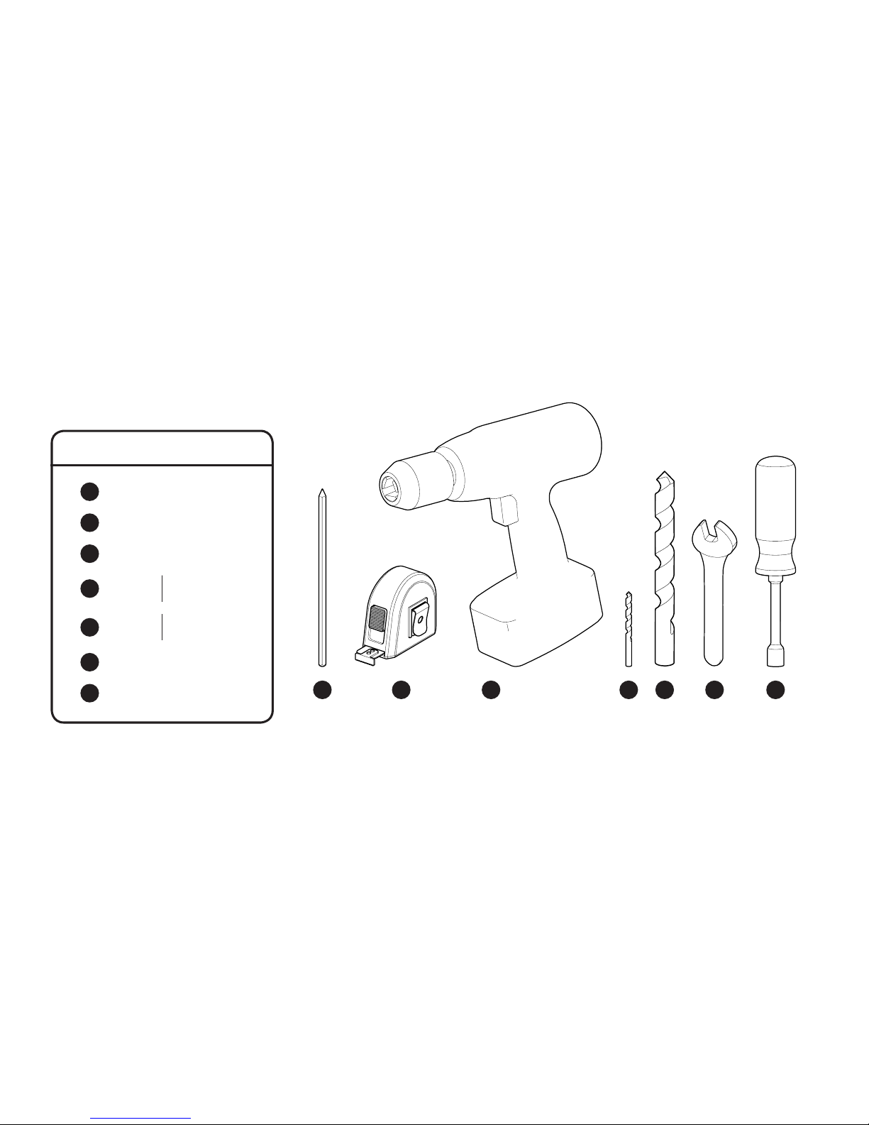
Tools Required
A
Pencil
C
Drill
B
Tape Measure
G
Socket Screwdriver
D
6mm
1/4”
Drill Bit
E
16mm
5/8”
Drill Bit
F
10mm Spanner
CB
Page 6

Configuration Options
Page 7
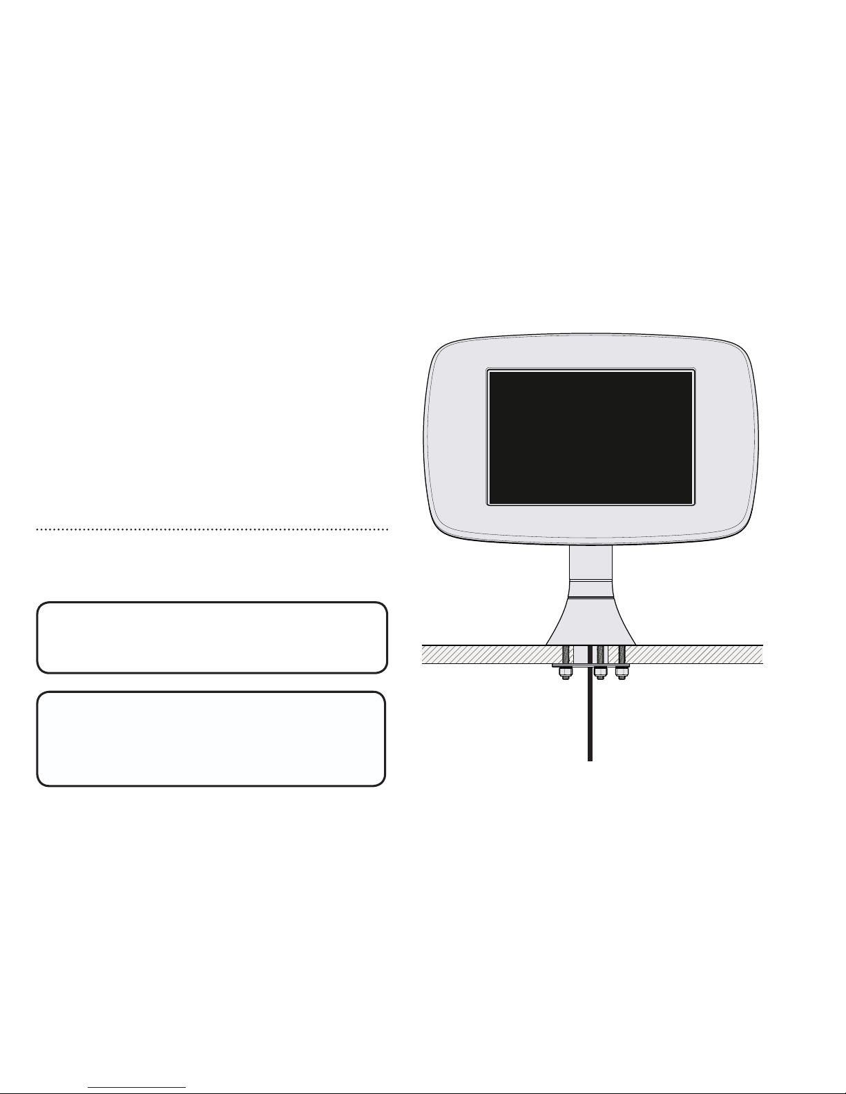
Fixing From Below
A
If fixing your Sumo from below
your mounting surface follow: A
The mounting surface must not
be thicker than 25mm or 1” for
this option.
Configuration
Page 8
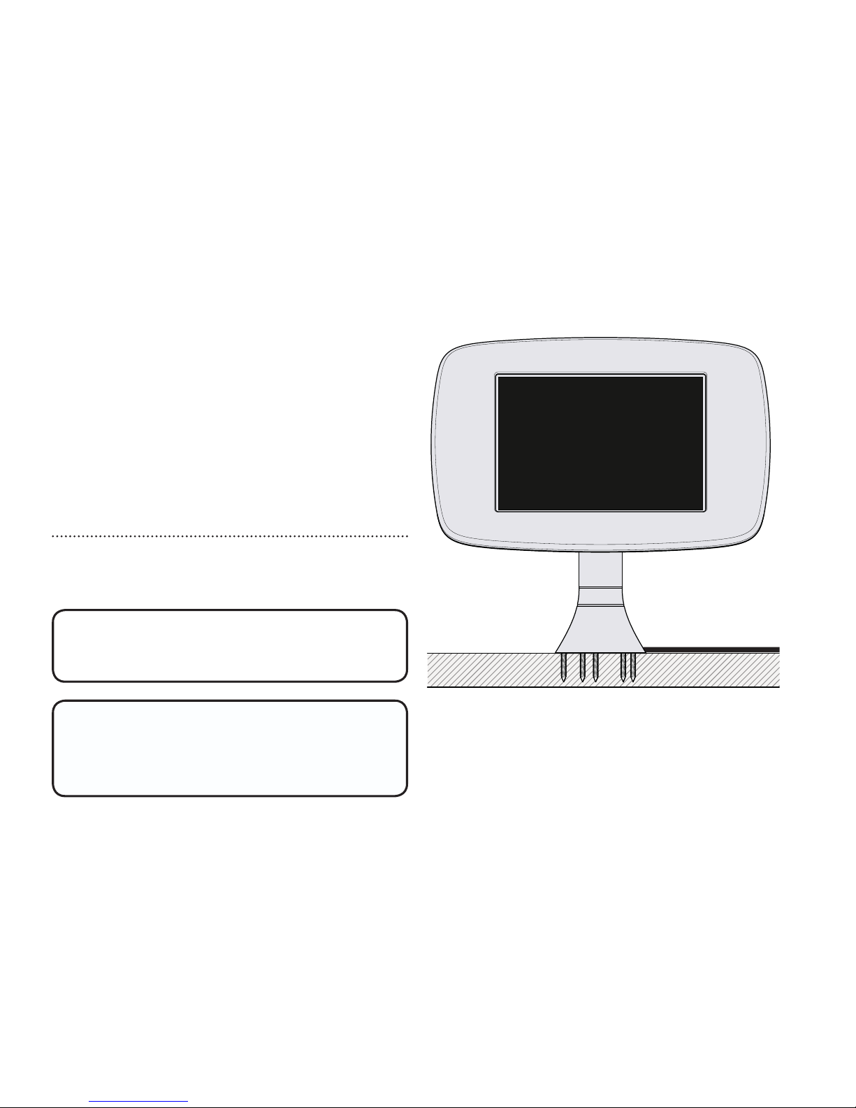
Fixing From Above
B
If fixing your Sumo from above
your mounting surface follow: B
Configuration
Screws must be no shorter than
30mm or 1 1/4” for this option.
*(screws not supplied)
Page 9
Ensure that you follow the
correct section for your chosen
mounting configuration.
Page 10
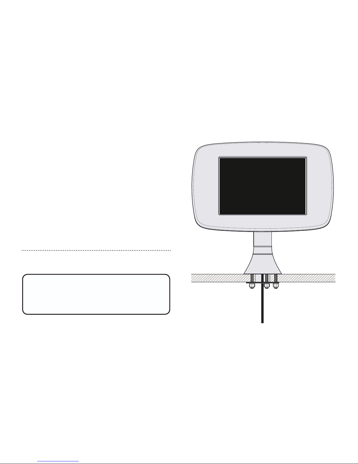
The mounting surface must not
be thicker than 25mm or 1” for
this option.
Fixing From Below
A
Configuration
Page 11
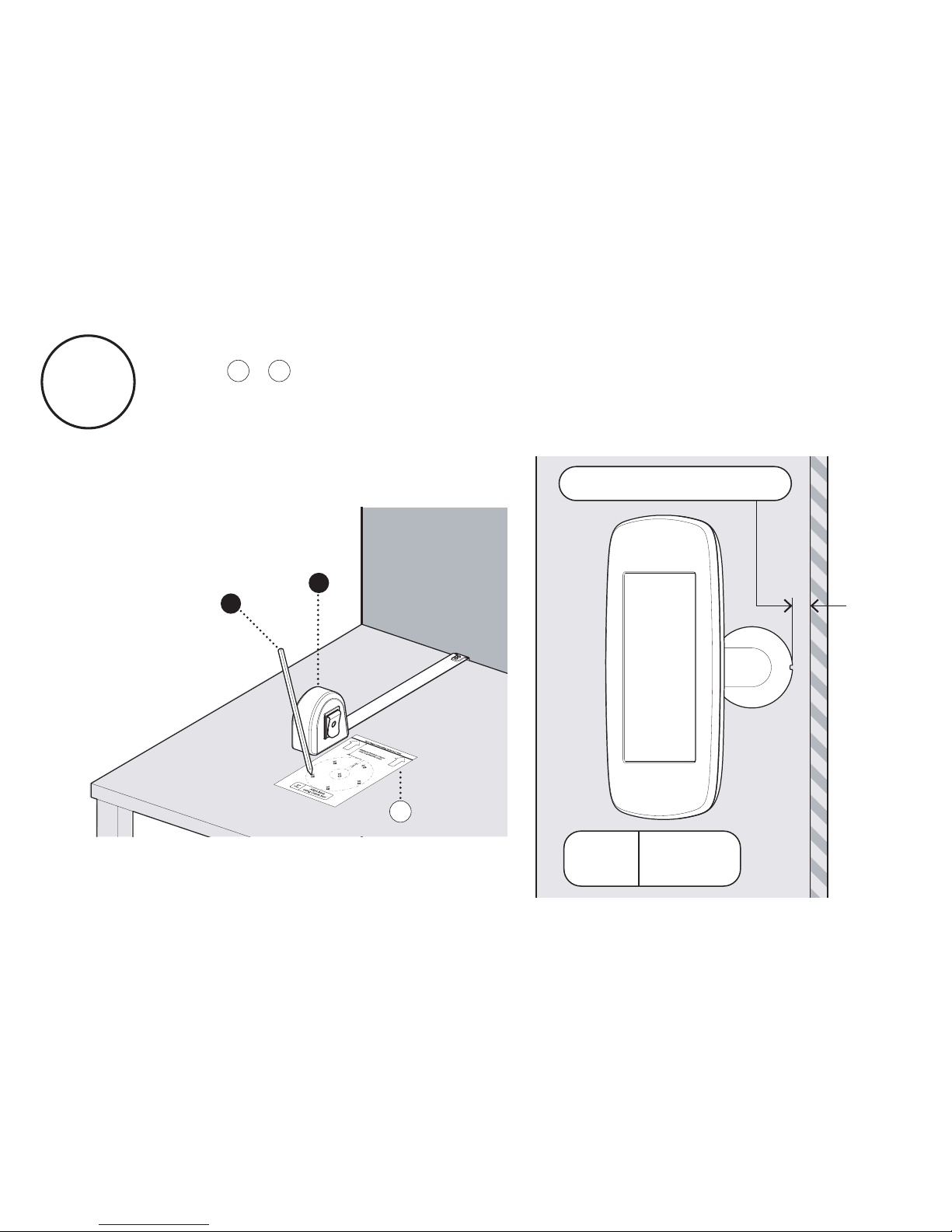
A1
B
A
A2
If your Sumo Stalk Base Rotation is configured to off, follow
steps + . Mark out the positions for the Mounting Holes.
Please note that your chosen rotate configuration will determine
the minimum distance you can mount Sumo from a wall.
A2A1
0º
Rotate
Plan
View
Minimum Distance:
30mm
Page 12
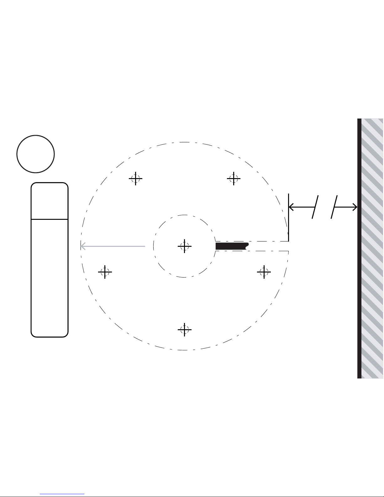
Rear Edge of Mounting Surface or Wall
E D
D
D
D
D
Align Base
using Cable Slot
0º
Rotate
30mm - Minimum Distance
Screen Direction
Cable Slot
A2
Page 13
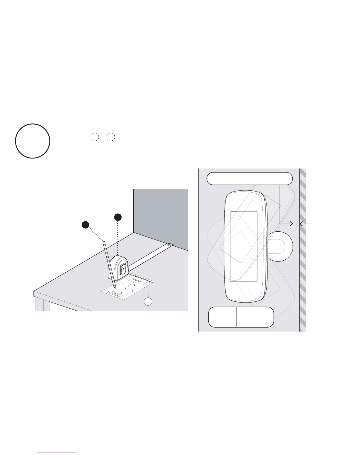
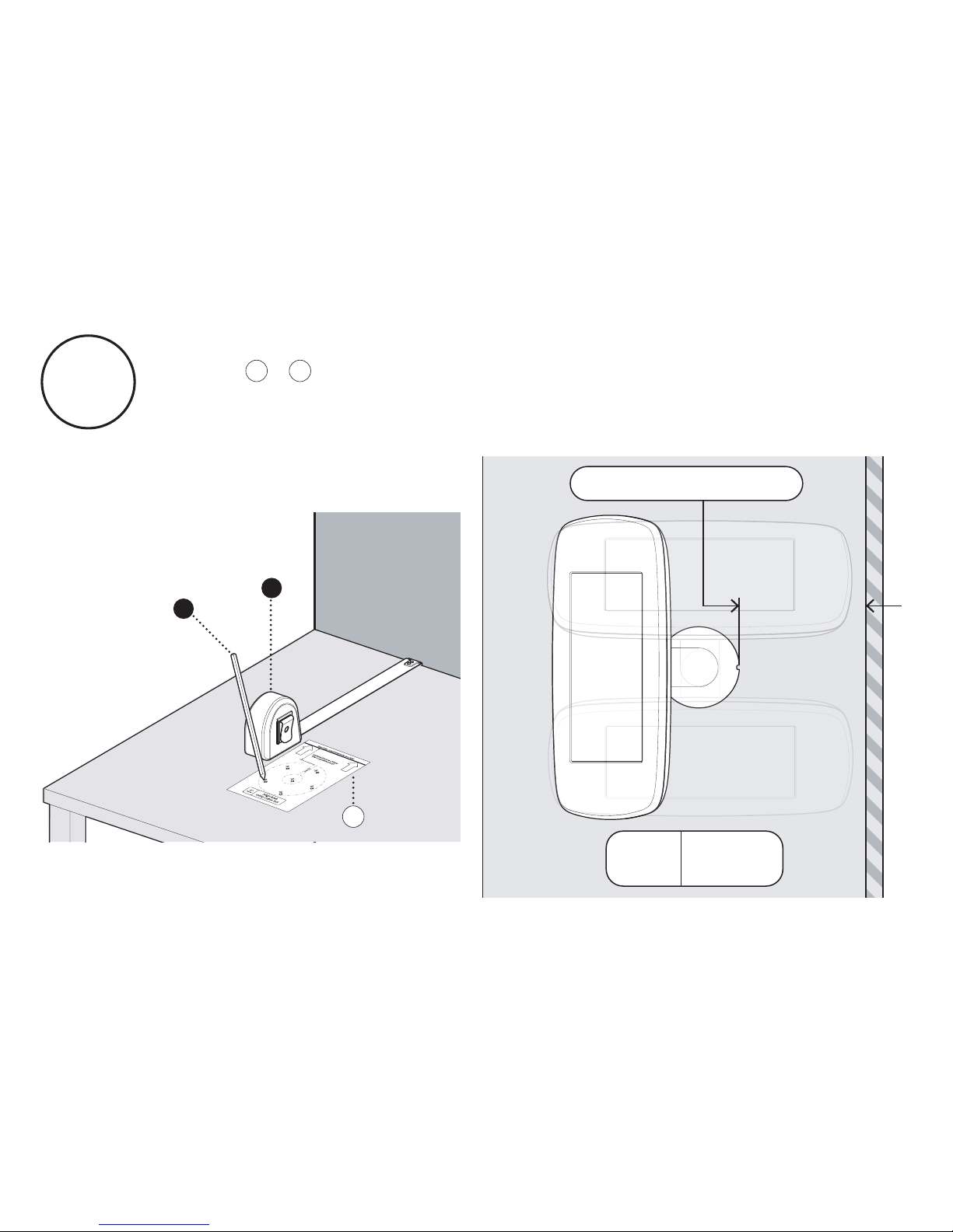
If your Sumo Stalk Base is configured for a 70° Rotation
follow + . Mark out the positions for the Mounting Holes.
Please note that your chosen rotate configuration will determine
the minimum distance you can mount Sumo from a wall.
A3
A4A3
B
A
A4
Minimum Distance:
30mm
70º
Rotate
Plan
View
Page 14
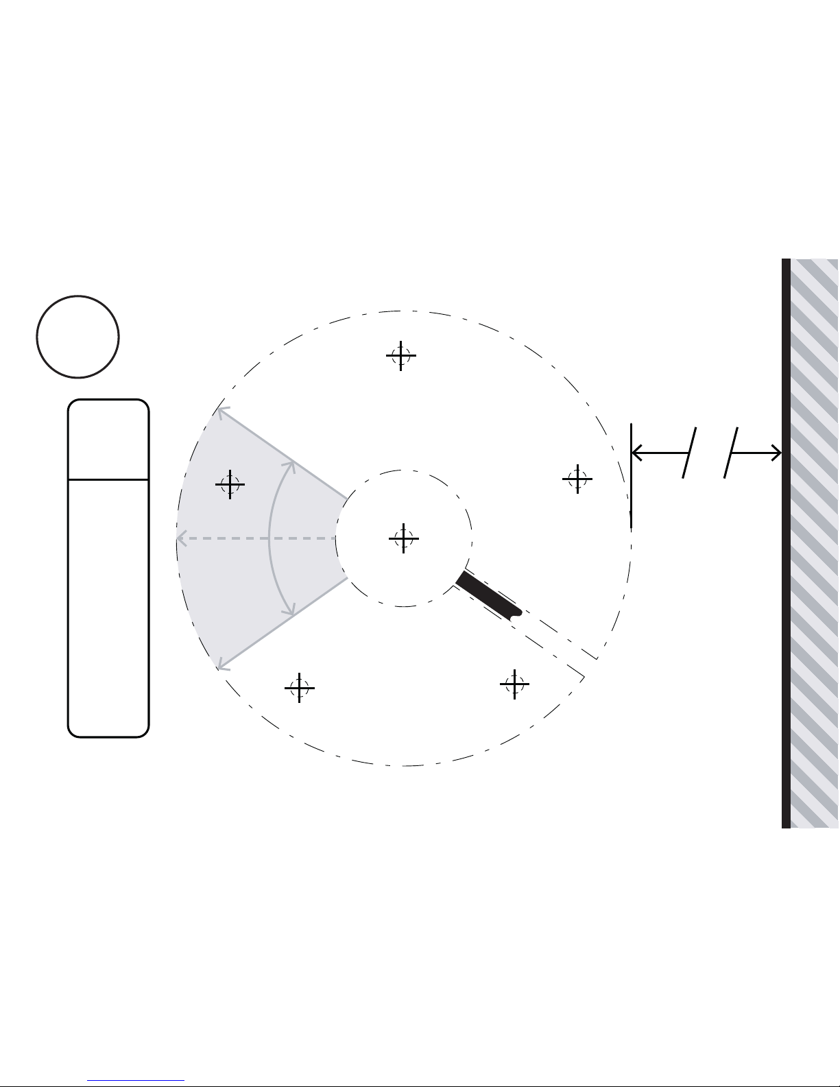
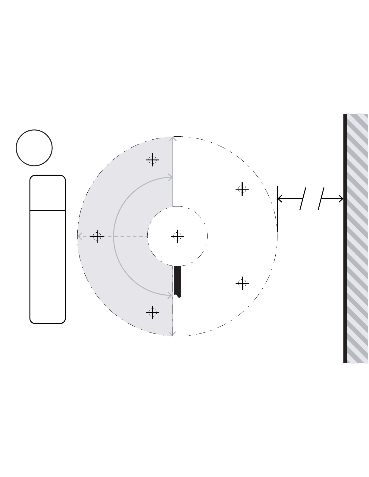
Rear Edge of Mounting Surface or Wall
E
D
D
D
D
D
Align Base
using Cable Slot
70º
Rotate
30mm - Minimum Distance
Cable Slot
Screen Direction
Screen Direction
Screen Centre Position
A4
Page 15
If your Sumo Stalk Base is configured for a 180° Rotation
follow + . Mark out the positions for the Mounting Holes.
Please note that your chosen rotate configuration will determine
the minimum distance you can mount Sumo from a wall.
A5
A6A5
B
A
A6
Minimum Distance:
135mm
180º
Rotate
Plan
View
Page 16
Screen Centre Position
Screen Direction
Screen Direction
Rear Edge of Mounting Surface or Wall
Cable Slot
E
D
D
D
D
D
Align Base
using Cable Slot
180º
Rotate
135mm - Minimum Distance
A6
Page 17
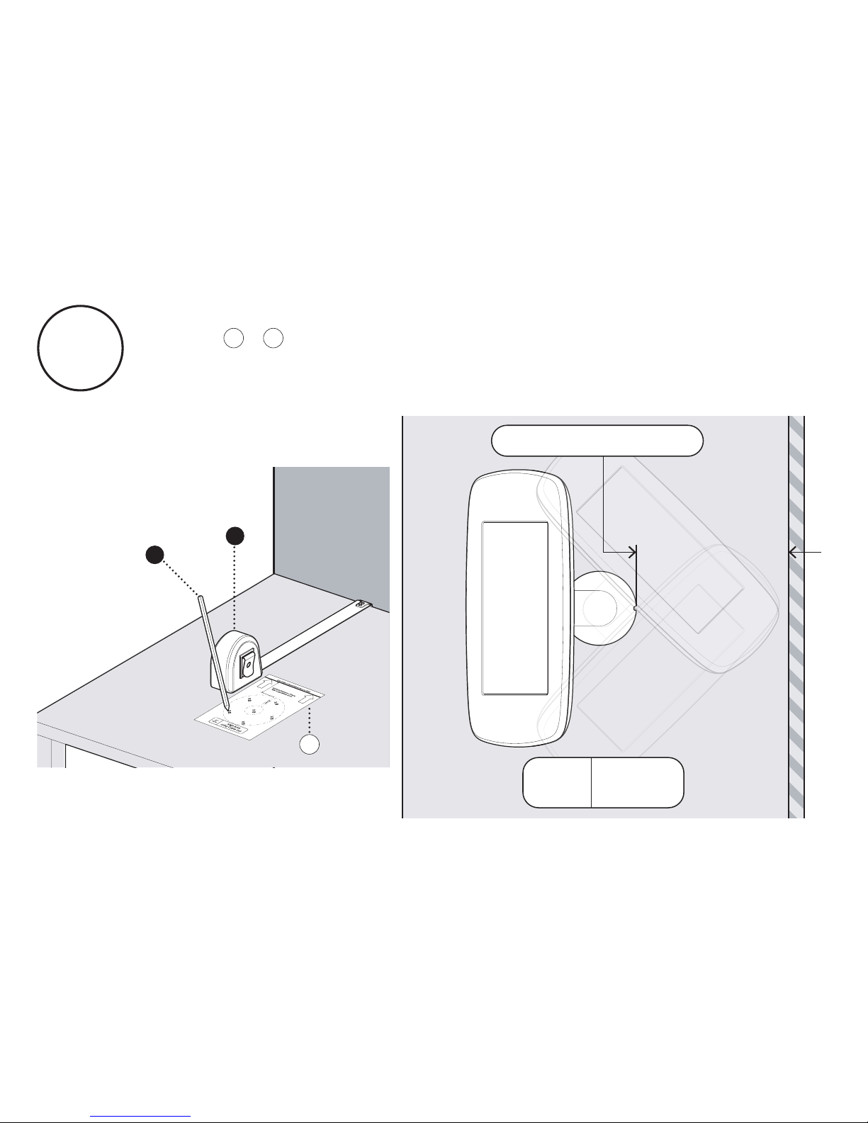
If your Sumo Stalk Base is configured for a 270° Rotation
follow + . Mark out the positions for the Mounting Holes.
Please note that your chosen rotate configuration will determine
the minimum distance you can mount Sumo from a wall.
A7
A8A7
B
A
A8
Minimum Distance:
180mm
270º
Rotate
Plan
View
Page 18
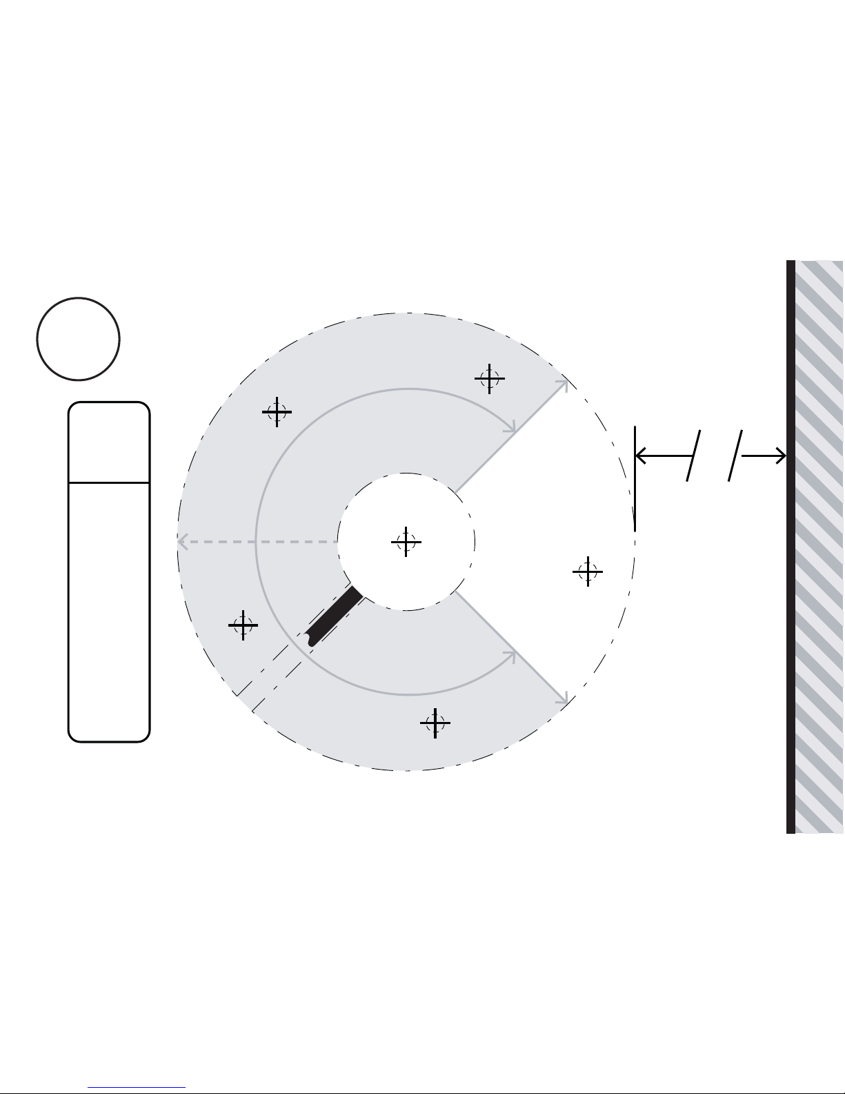
Rear Edge of Mounting Surface or Wall
E
D
D
D
D
D
Align Base
using Cable Slot
270º
Rotate
180mm - Minimum Distance
Cable Slot
Screen Direction
Screen Direction
Screen Centre Position
A8
Page 19
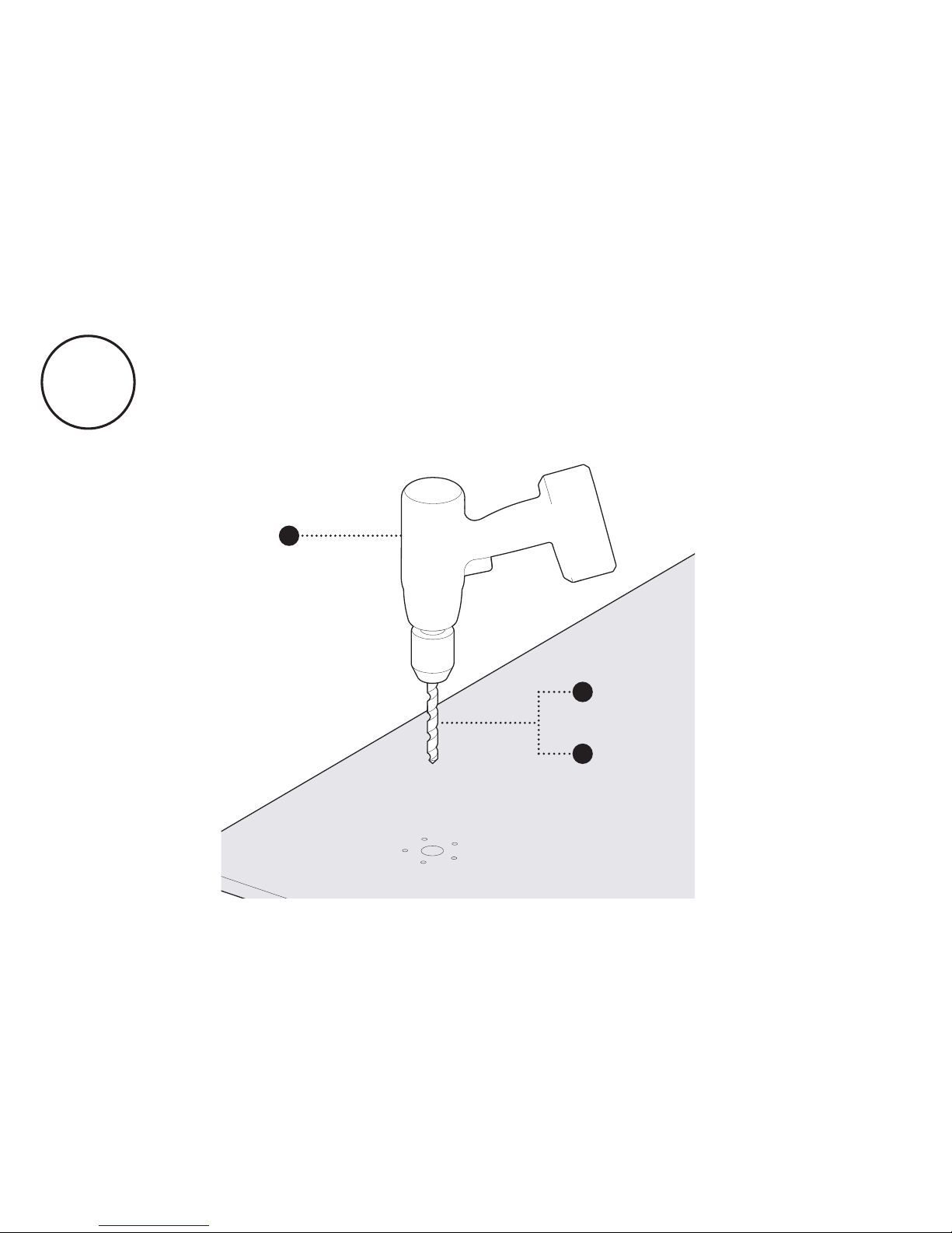
Drill the mounting holes in your surface using the
appropriate Below Surface Mounting Template for your
rotate configuration - these guidelines can be found on the
previous pages of this booklet.
A9
C
E
D
Page 20
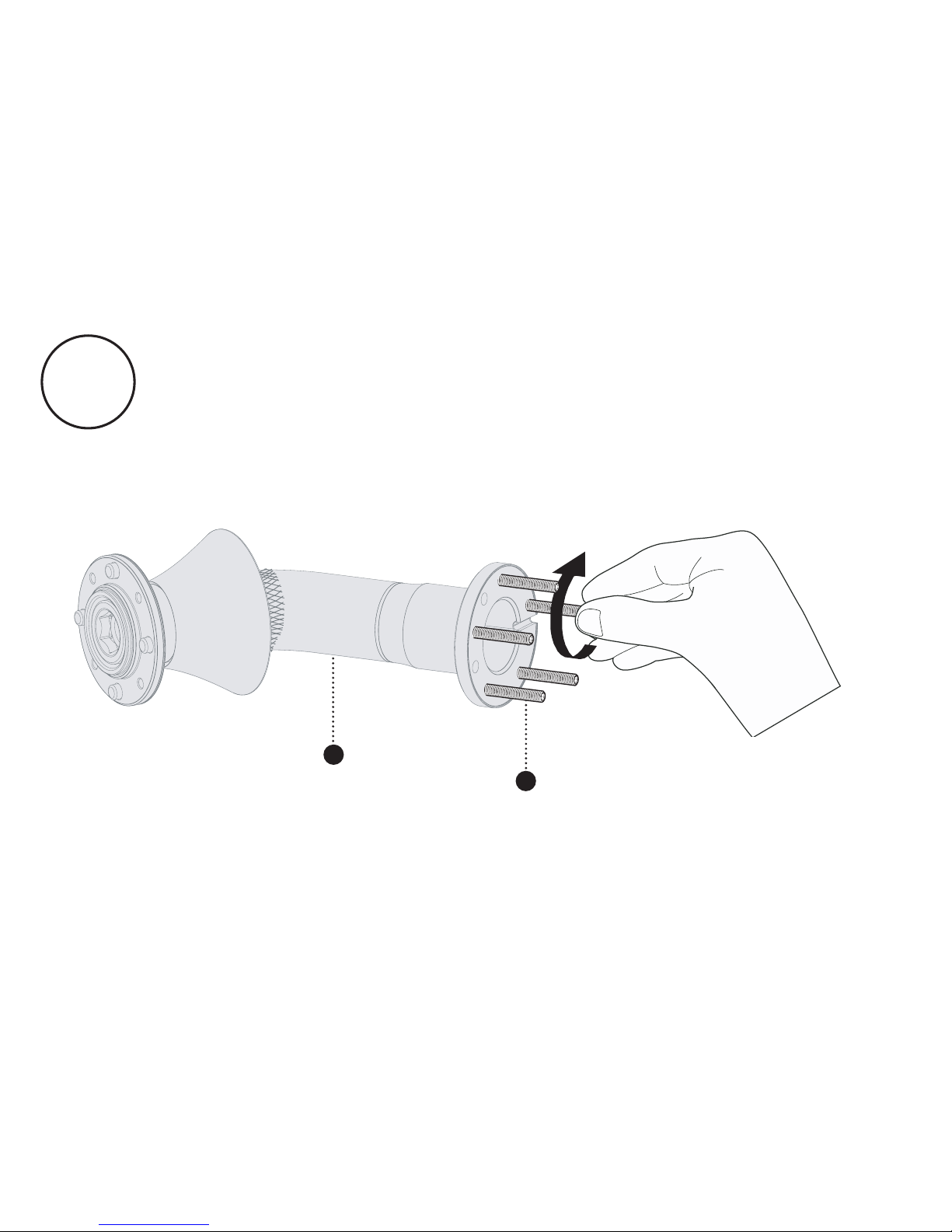
A10
Attach the socket set-screws into the base of the Sumo
Stalk. These screws must be tightened by hand to the full depth
of the internal thread - do not over tighten.
2
10
Page 21
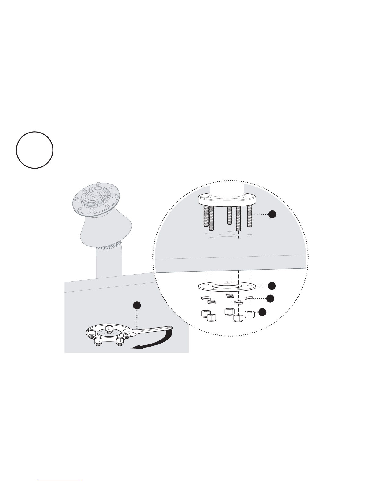
A11
Attach the Sumo Stalk to your surface. Tighten the Nyloc Nuts
to 4Nm or 2.9 ft-lb. The fixings must be installed in the correct
order.
F
10
3
7
9
Page 22
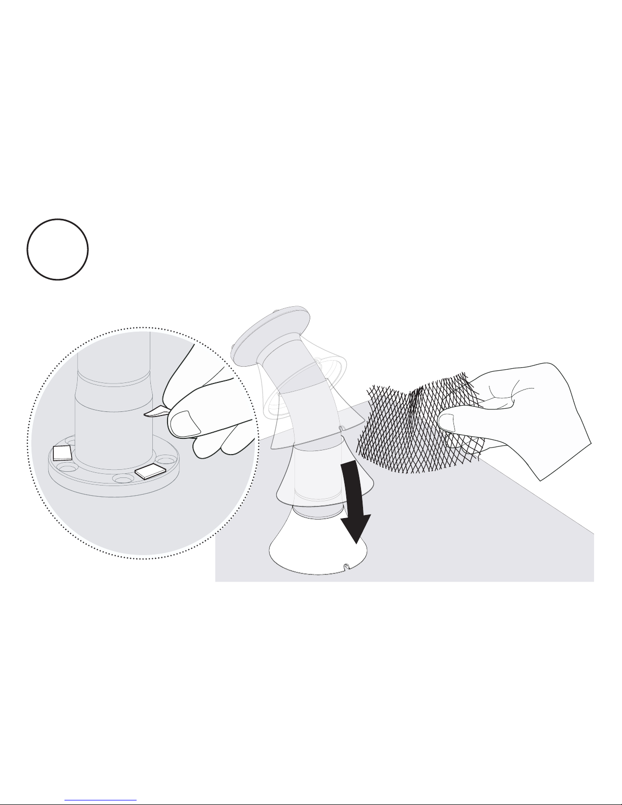
Unpeel the adhesive pads on the Stalk Base and carefully
slide the Stalk Cover onto the Stalk Base. Tear off the
protective netting. Ensure that the Stalk Cover is securely stuck
down.
A12
Page 23
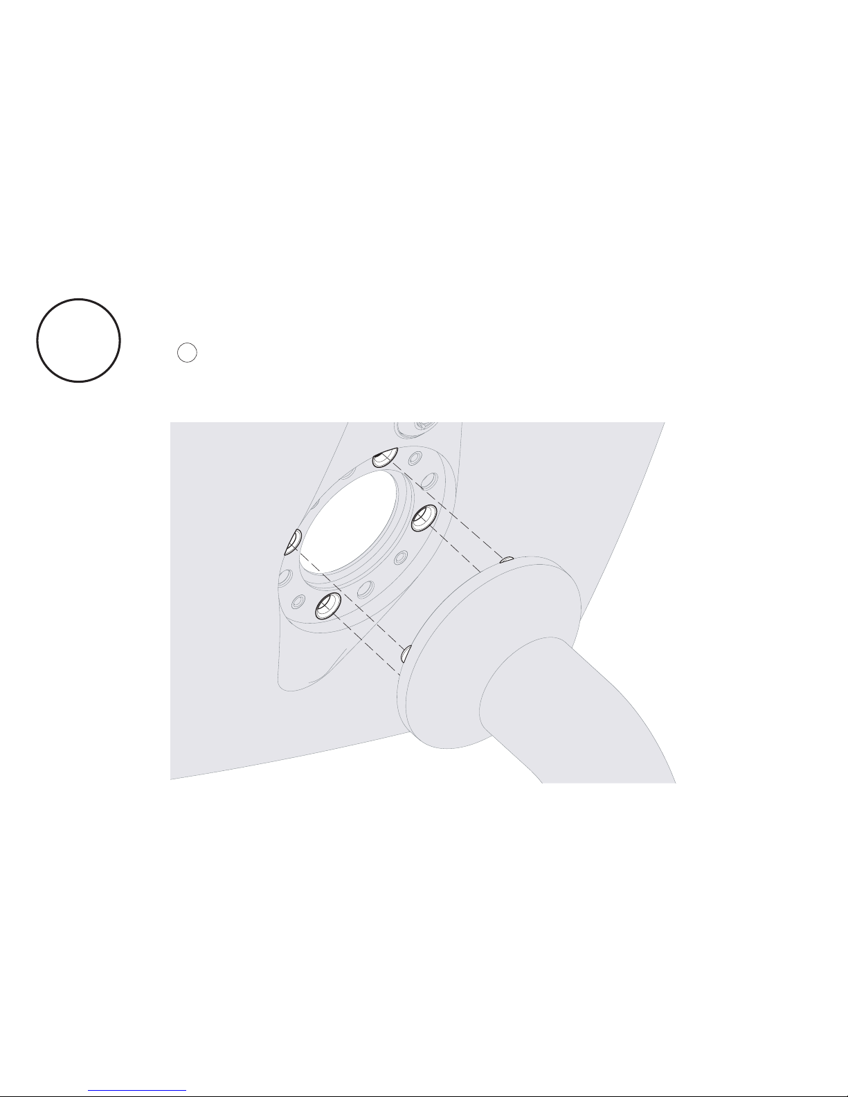
Locate the Sumo Case onto the Sumo Stalk using the metal
locating pins on the Sumo Stalk. Please refer to the guidelines
on to correctly configure the case orientation according to
your chosen switch configuration.
A13
A14
Page 24
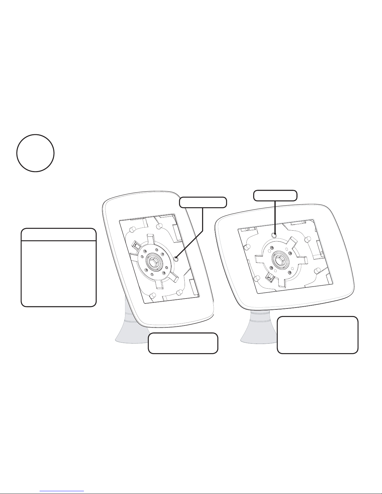
A14
Landscape Orientation -
Switch Disabled
Switch Enabled
or
Hint:
Switch Configuration
means whether the
Neck of the Stalk
allows the screen to
rotate from portrait
to landscape, or if
the screen is locked
in a static position.
Lock at Top
Lock on Right
Portrait Orientation -
Switch Disabled
Follow the guidelines below to correctly orientate
your Sumo Case - appropriate to your specified Switch
Configuration and chosen Case Orientation.
Page 25
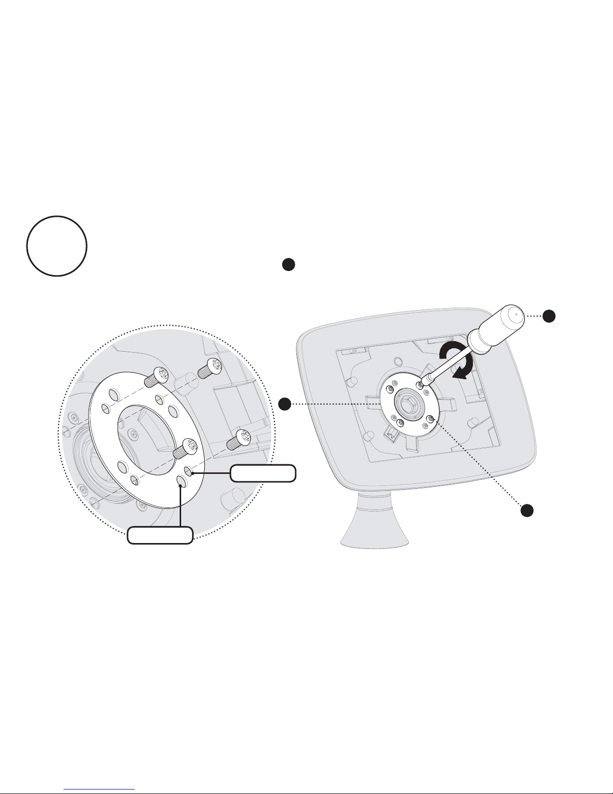
Secure the Sumo Case onto the Sumo Stalk. Ensure the Case
Clamping Plate is orientated correctly - it must sit flush with the
case. Tighten the screws ( ) to 2Nm or 1.5 ft-lb.
6
4
6
G
Small Hole
Large Hole
A15
Page 26
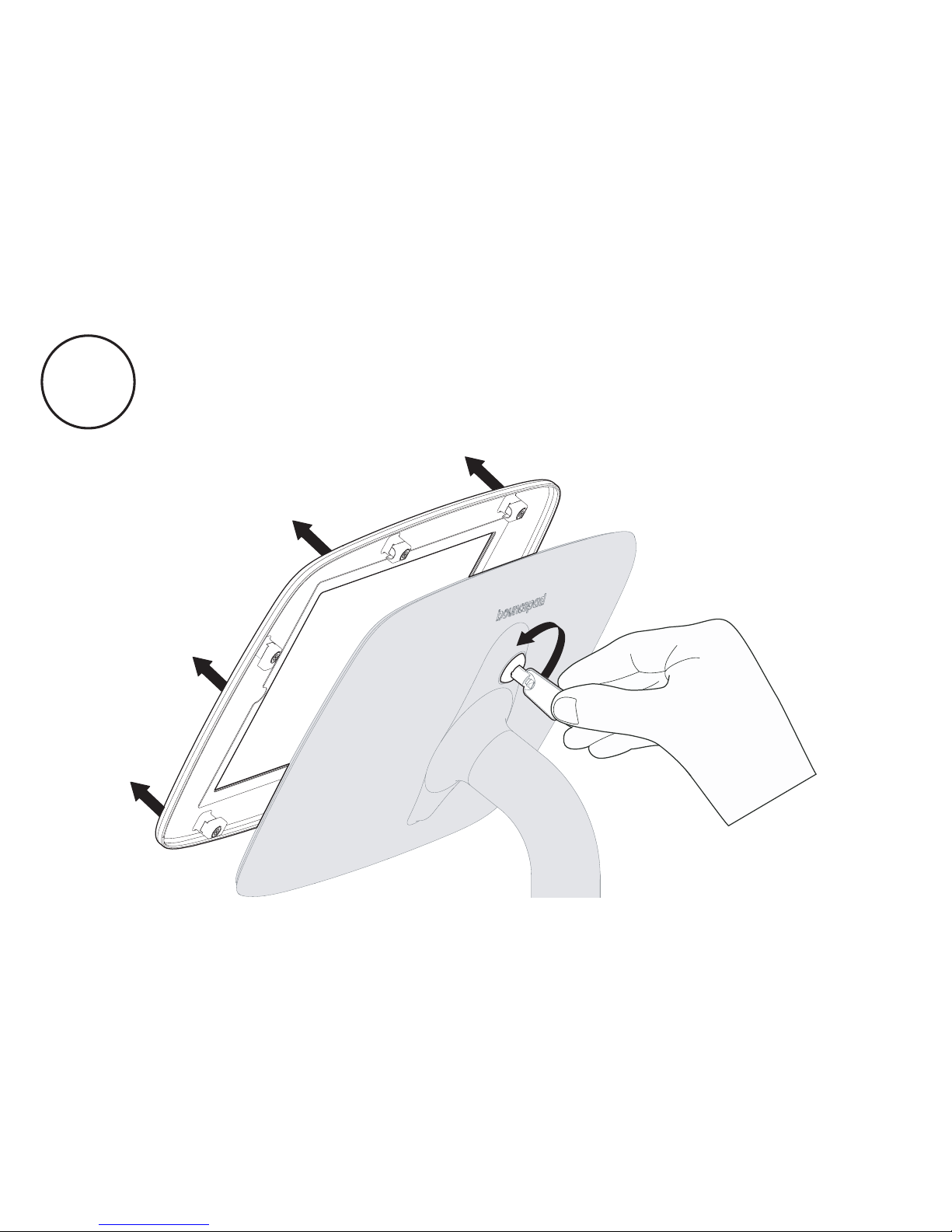
Unlock and remove the Sumo Faceplate.
A16
Page 27
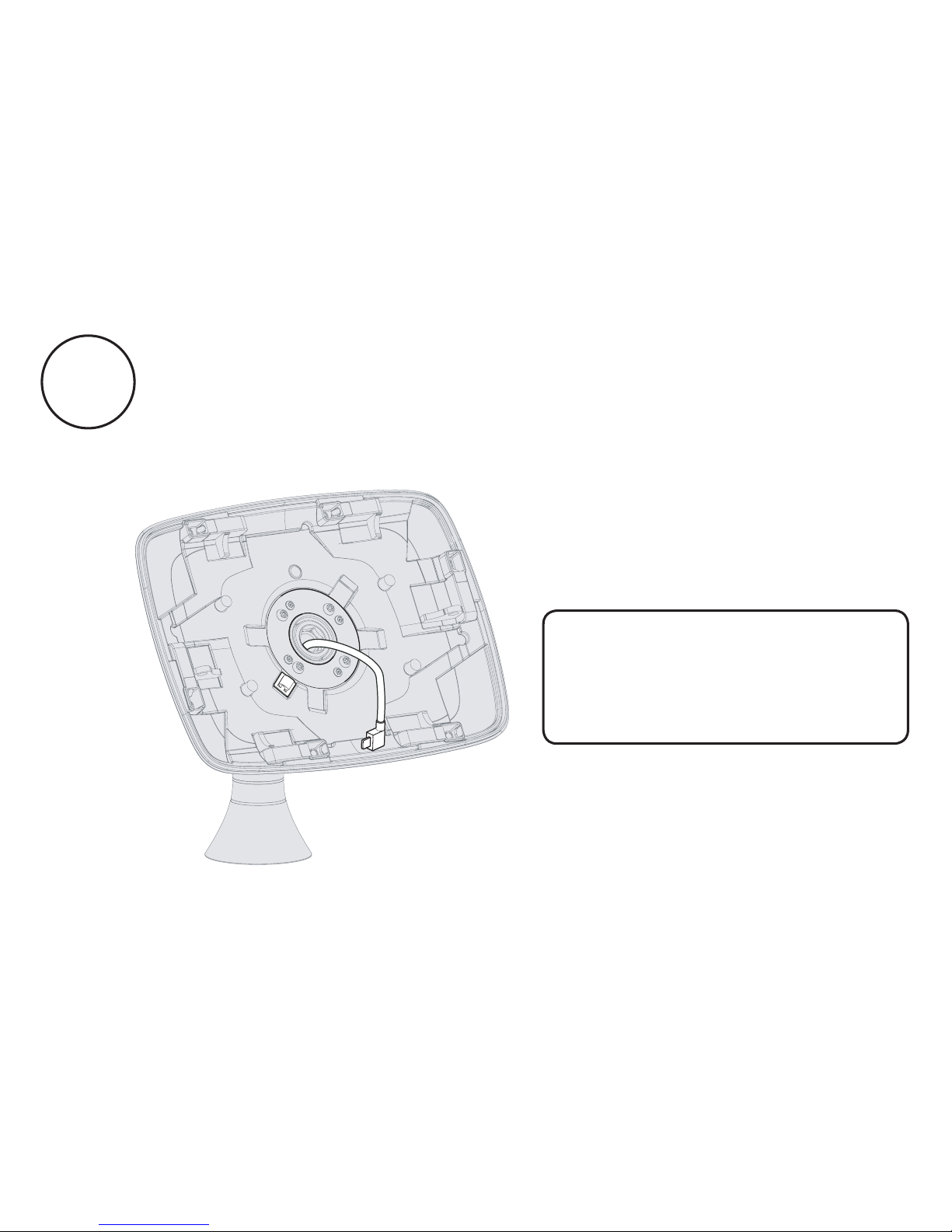
Feed your tablet cabling through the centre of the case and
Case Clamping Plate. Clip the cable into place.
A17
Where the power cable
is connected to a power
transformer, the cable must
be fed from below.
Page 28
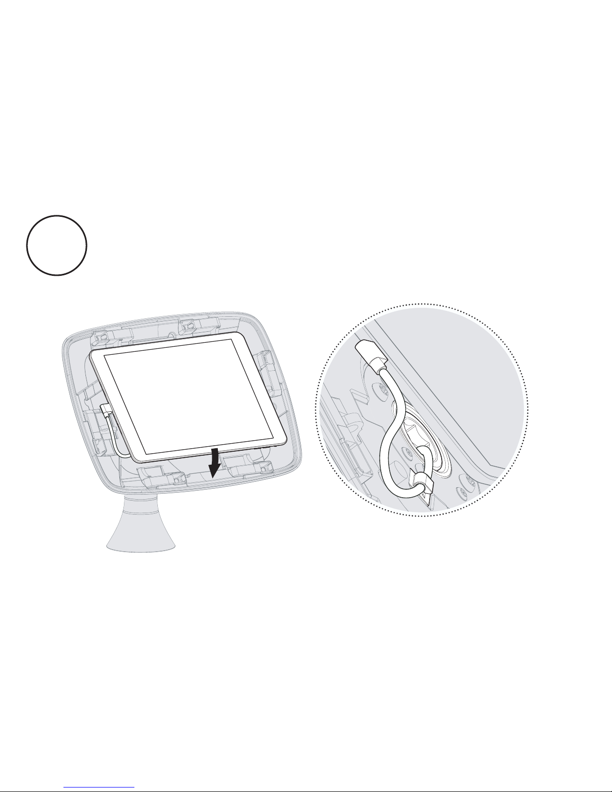
Connect the cable to your tablet and place into the secure
case. Your Sumo is configured to house the tablet as specified
within your order. If you need to use a different tablet, please
contact us.
A18
Page 29
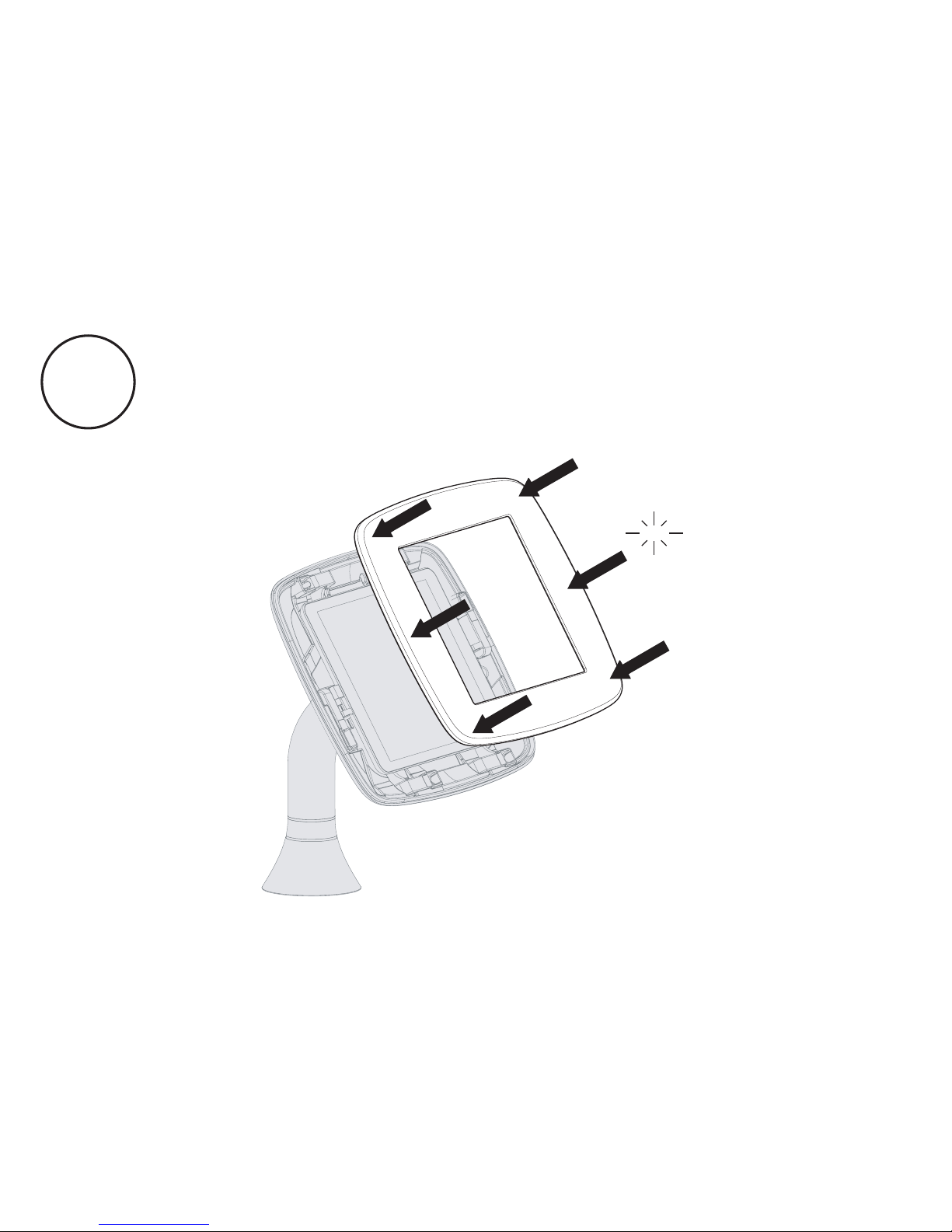
Attach the Sumo faceplate securely onto the main case
body. Press the faceplate onto the case - ensuring all edges are
locked securely in place.
A19
Click
Click
Page 30
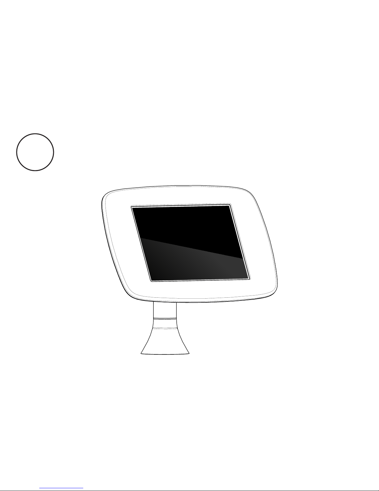
Finally, connect your tablet to its power source. You
have assembled your Sumo enclosure and it is now
ready for use.
A20
Page 31
If you have any queries, please
contact our Customer Care Team.
Page 32
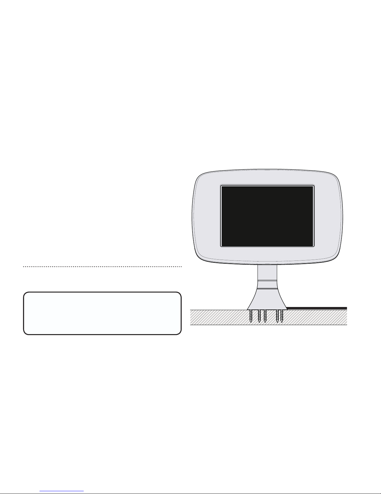
Screws must be no shorter than
30mm or 1 1/4” for this option.
*(screws not supplied)
Configuration
B
Fixing From Above
Page 33
B1
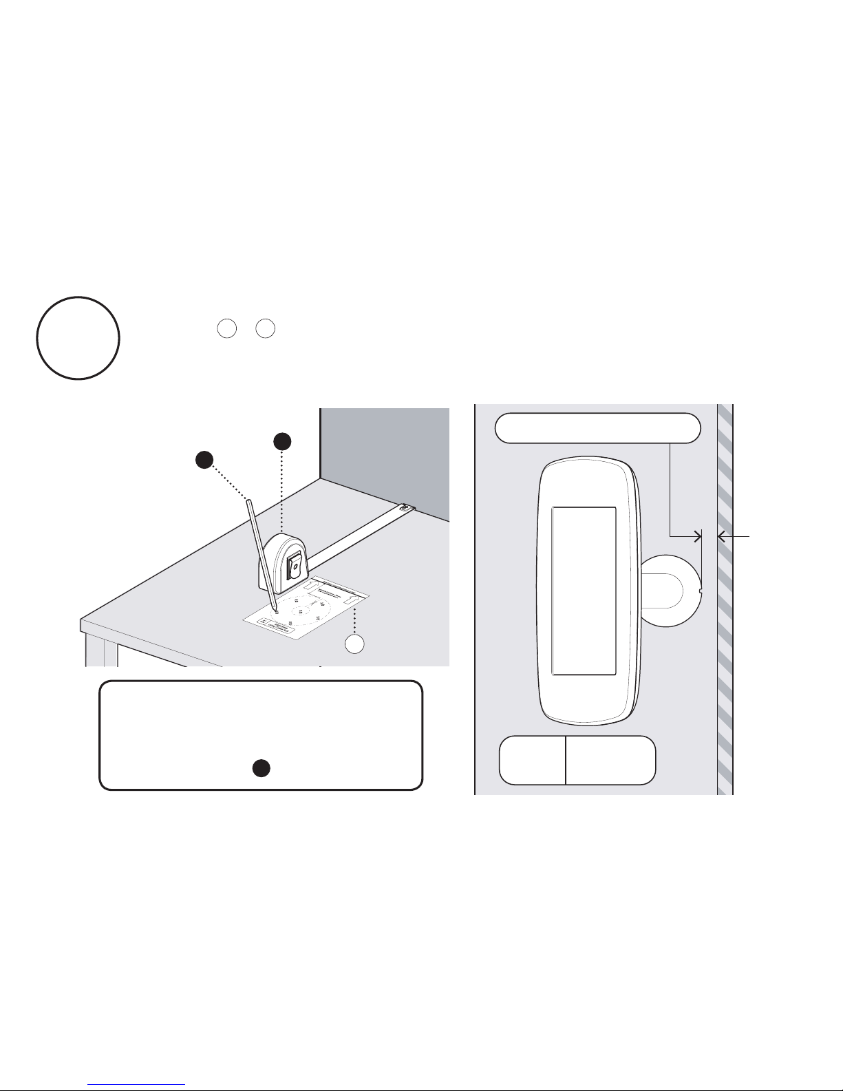
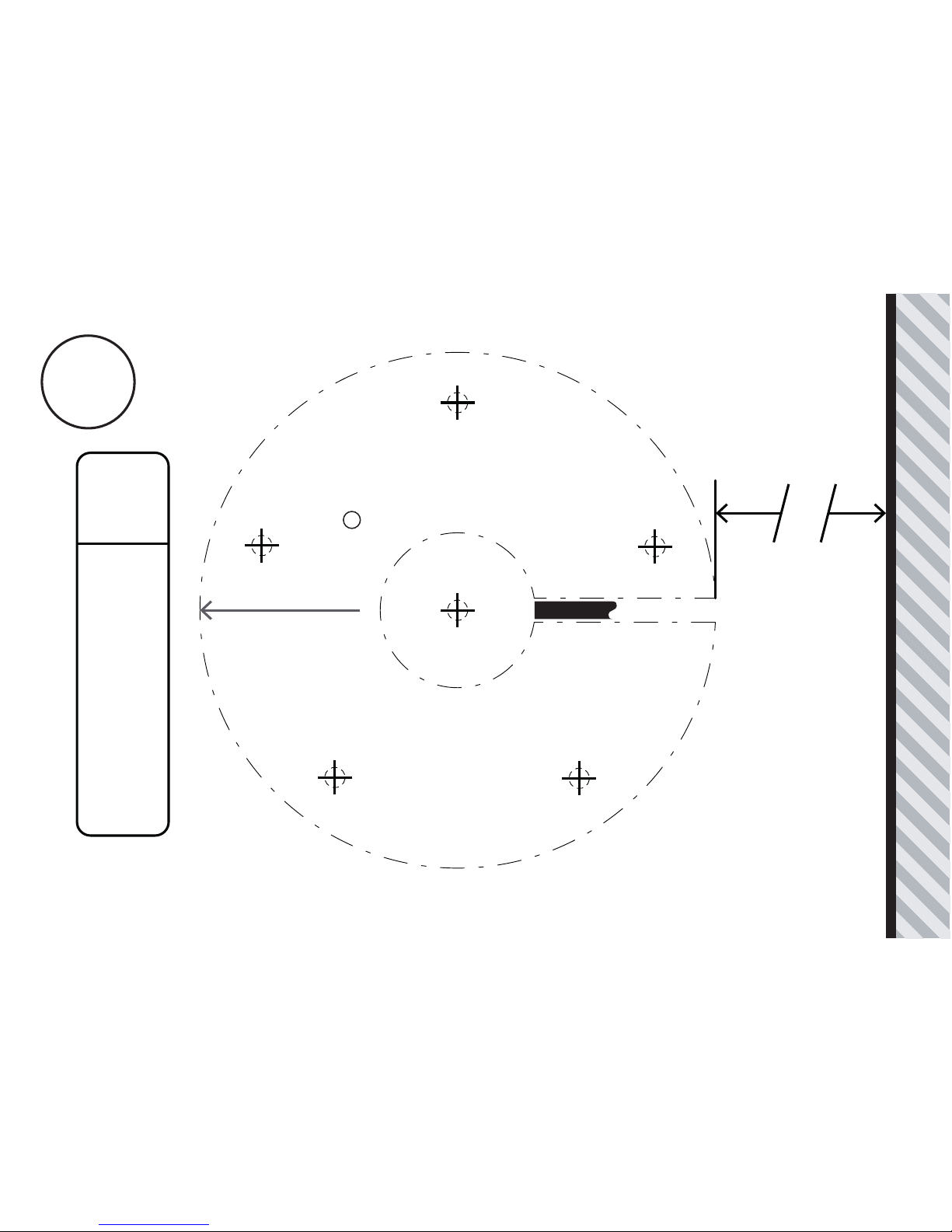
If your Sumo Stalk Base is configured for a 0° Rotation
follow + . Mark out the positions for the Mounting Holes.
Please note your chosen rotate configuration will determine the
minimum distance that you can mount Sumo from a wall.
B2B1
If you wish to insert the
tablet cabling through your
surface, please mark and
drill position .
E
B
A
B2
0º
Rotate
Plan
View
Minimum Distance:
30mm
Page 34
Rear Edge of Mounting Surface or Wall
Align Base
using Cable Slot
0º
Rotate
E
30mm - Minimum Distance
Drill Position if you
wish to route the cable
through your surface.
E
Screen Direction
Cable Slot
B2
Page 35
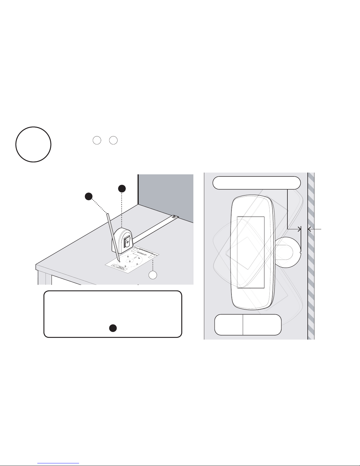
B3
If your Sumo Stalk Base is configured for a 70° Rotation
follow + . Mark out the positions for the Mounting Holes.
Please note your chosen rotate configuration will determine the
minimum distance that you can mount Sumo from a wall.
B4B3
If you wish to insert the
tablet cabling through your
surface, please mark and
drill position .
E
B
A
B4
Minimum Distance:
30mm
70º
Rotate
Plan
View
Page 36
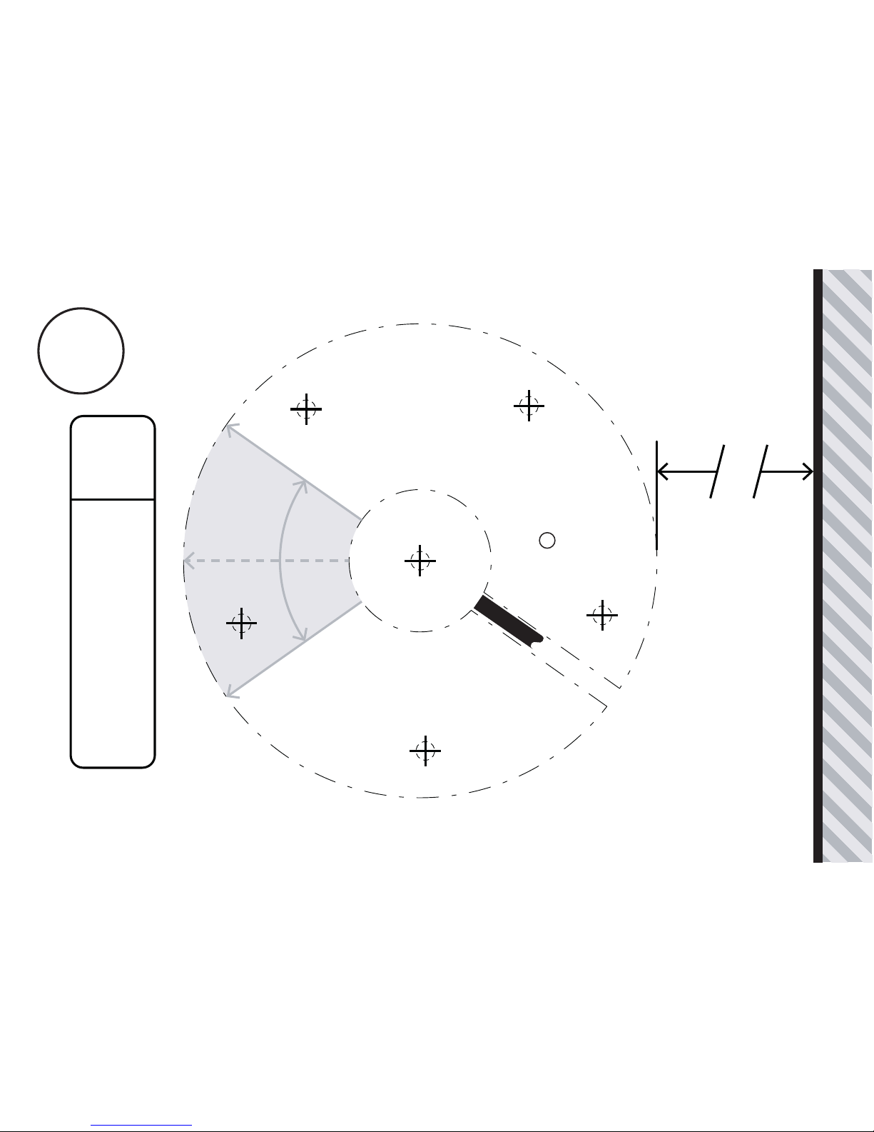
Rear Edge of Mounting Surface or Wall
Align Base
using Cable Slot
70º
Rotate
E
30mm - Minimum Distance
Drill Position if you
wish to route the cable
through your surface.
E
Cable Slot
Screen Direction
Screen Direction
Screen Centre Position
B4
Page 37
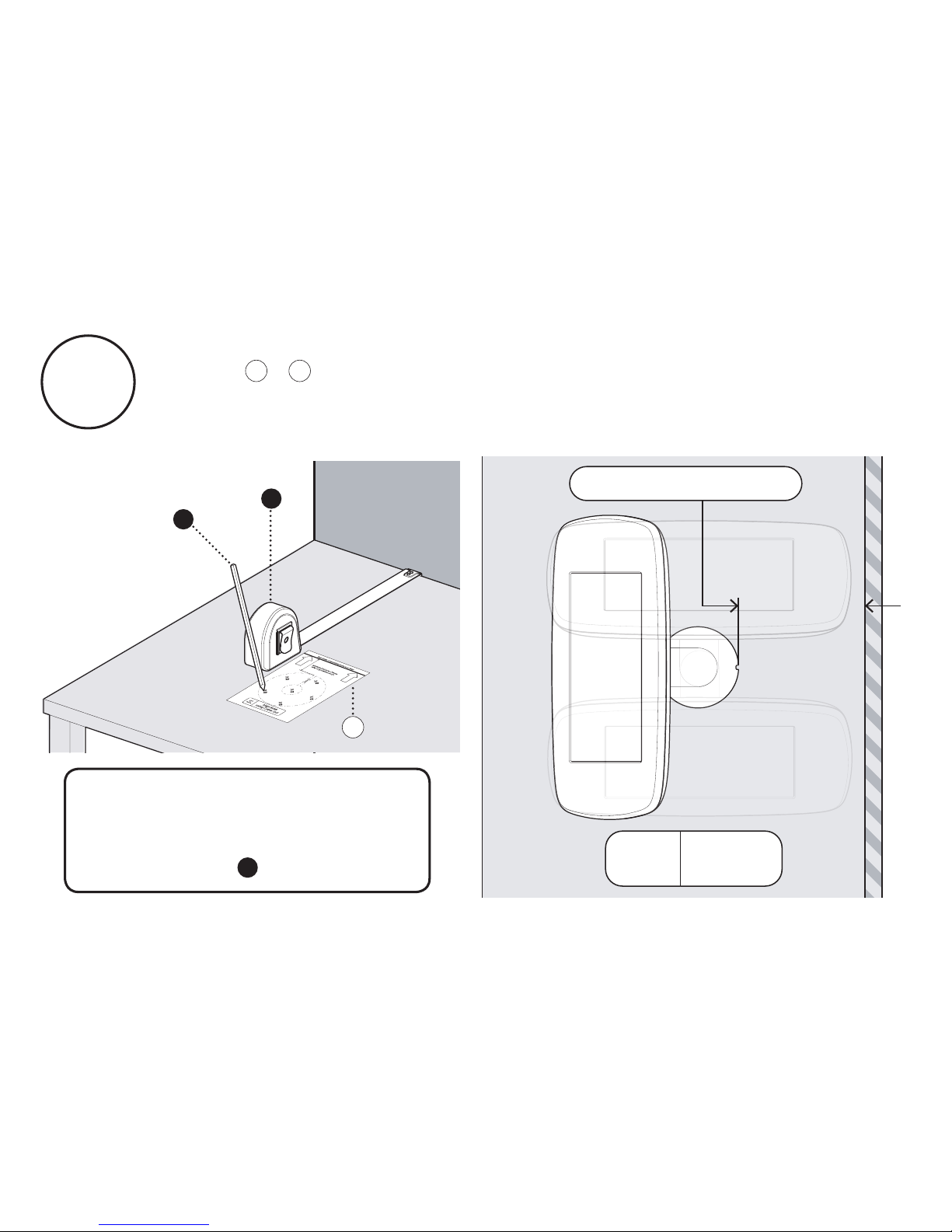
B5
If your Sumo Stalk Base is configured for a 180° Rotation
follow + . Mark out the positions for the Mounting Holes.
Please note your chosen rotate configuration will determine the
minimum distance that you can mount Sumo from a wall.
B6B5
If you wish to insert the
tablet cabling through your
surface, please mark and
drill position .
E
B
A
B6
Minimum Distance:
135mm
180º
Rotate
Plan
View
Page 38
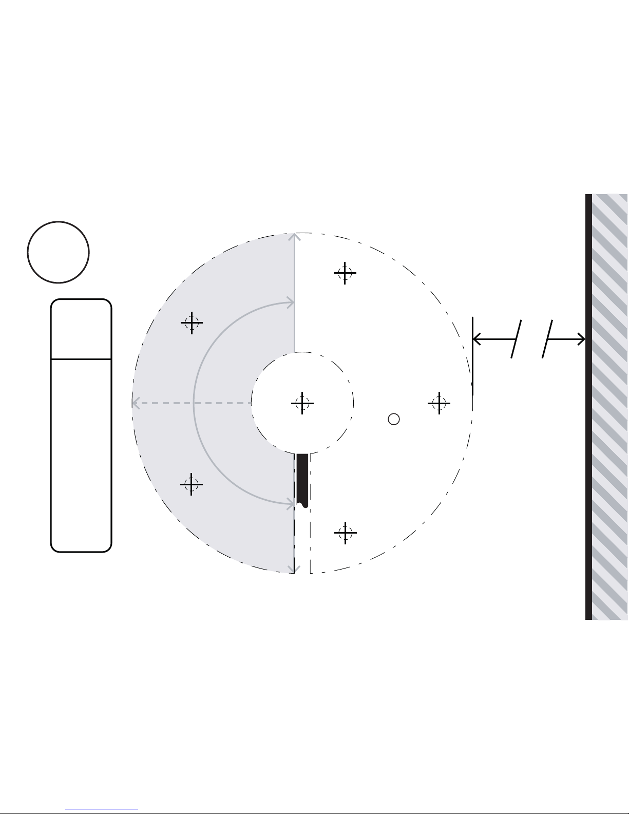
Cable Slot
Screen Direction
Screen Direction
Rear Edge of Mounting Surface or Wall
Align Base
using Cable Slot
180º
Rotate
E
135mm - Minimum Distance
Drill Position if you
wish to route the cable
through your surface.
E
Screen Centre Position
B6
Page 39
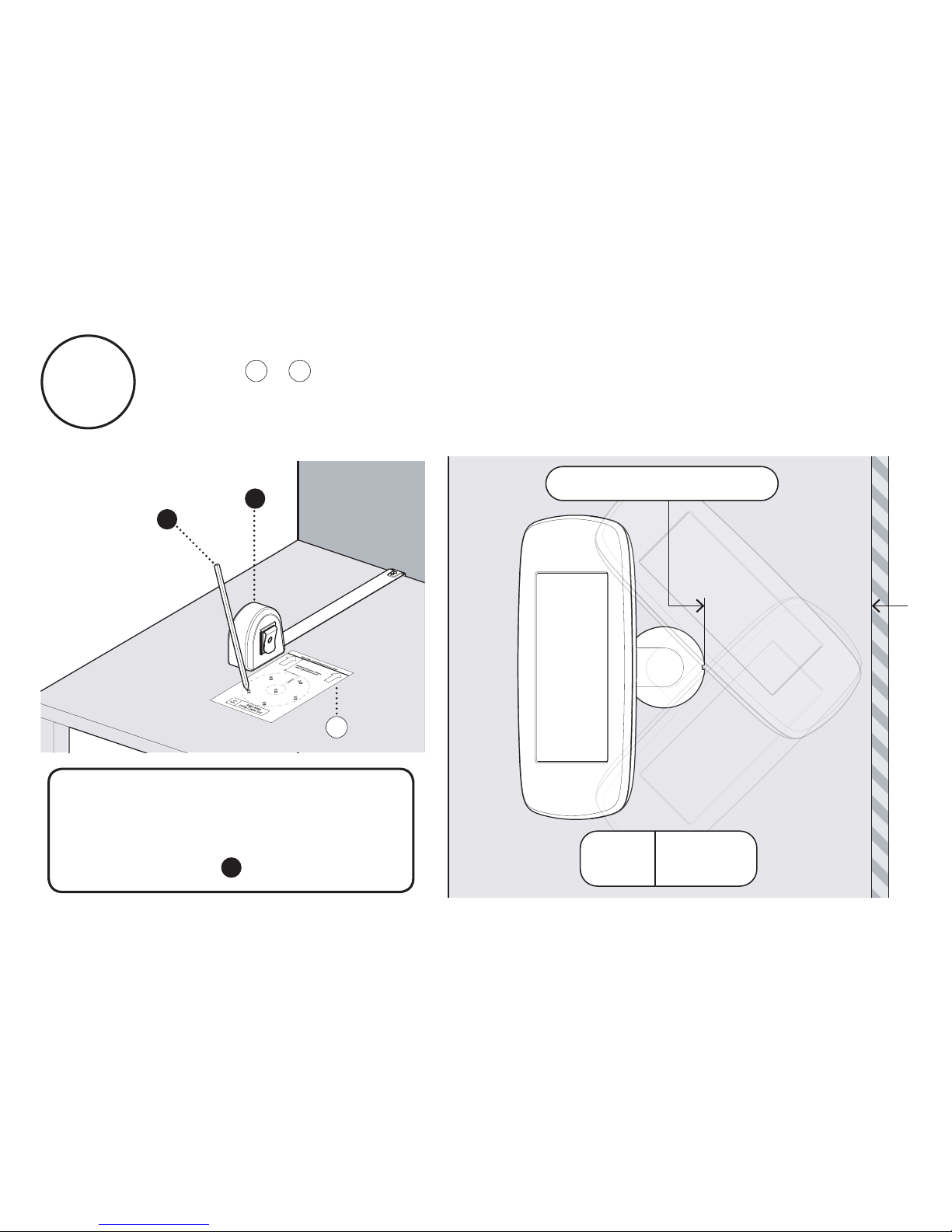
B7
If your Sumo Stalk Base is configured for a 270° Rotation
follow + . Mark out the positions for the Mounting Holes.
Please note your chosen rotate configuration will determine the
minimum distance that you can mount Sumo from a wall.
B8B7
If you wish to insert the
tablet cabling through your
surface, please mark and
drill position .
E
B
A
B8
Minimum Distance:
180mm
270º
Rotate
Plan
View
Page 40
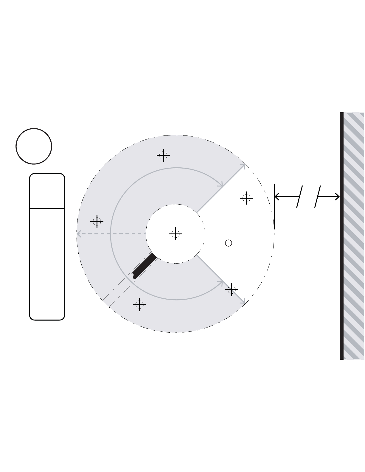
Rear Edge of Mounting Surface or Wall
Align Base
using Cable Slot
270º
Rotate
E
Drill Position if you
wish to route the cable
through your surface.
E
180mm - Minimum Distance
Cable Slot
Screen Direction
Screen Direction
Screen Centre Position
B8B8
Page 41

Page 42
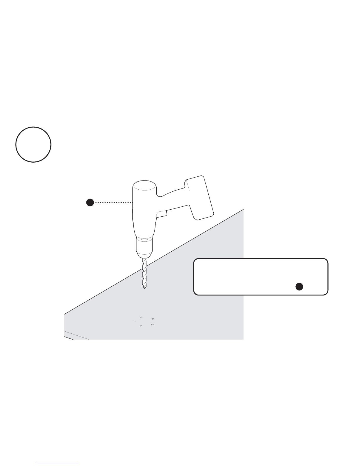
B9
If required, drill pilot holes appropriate for your mounting
material and screw type. Use the correct template for your
rotate configuration - these guidelines can be found on the
previous pages.
C
If you wish to insert the
tablet cabling through your
surface, drill position .
E
Page 43
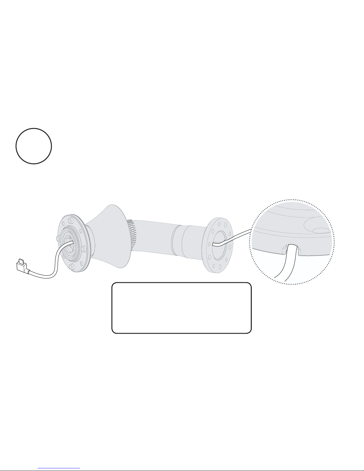
B10
Feed your tablet cable through the Sumo stalk. Ensure the
cable locates and remains within the cable slot in the base.
Where the power cable
is connected to a power
transformer, the cable must
be fed from below.
Page 44
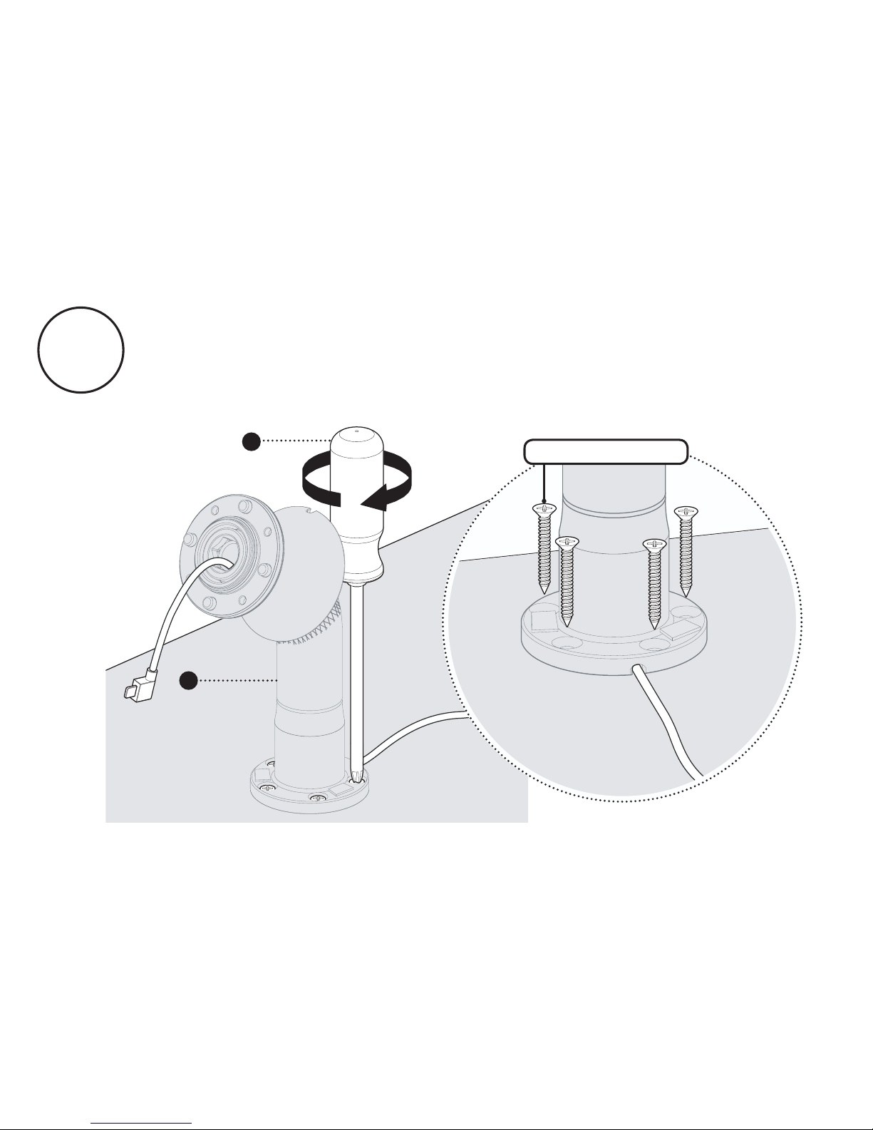
Attach the Sumo stalk to your mounting surface using
countersunk screws. The screws must not be shorter than 30mm
or 1 ¼ inches. For additional security, use anti-tamper screws.
G
2
B11
Screws not supplied
Page 45
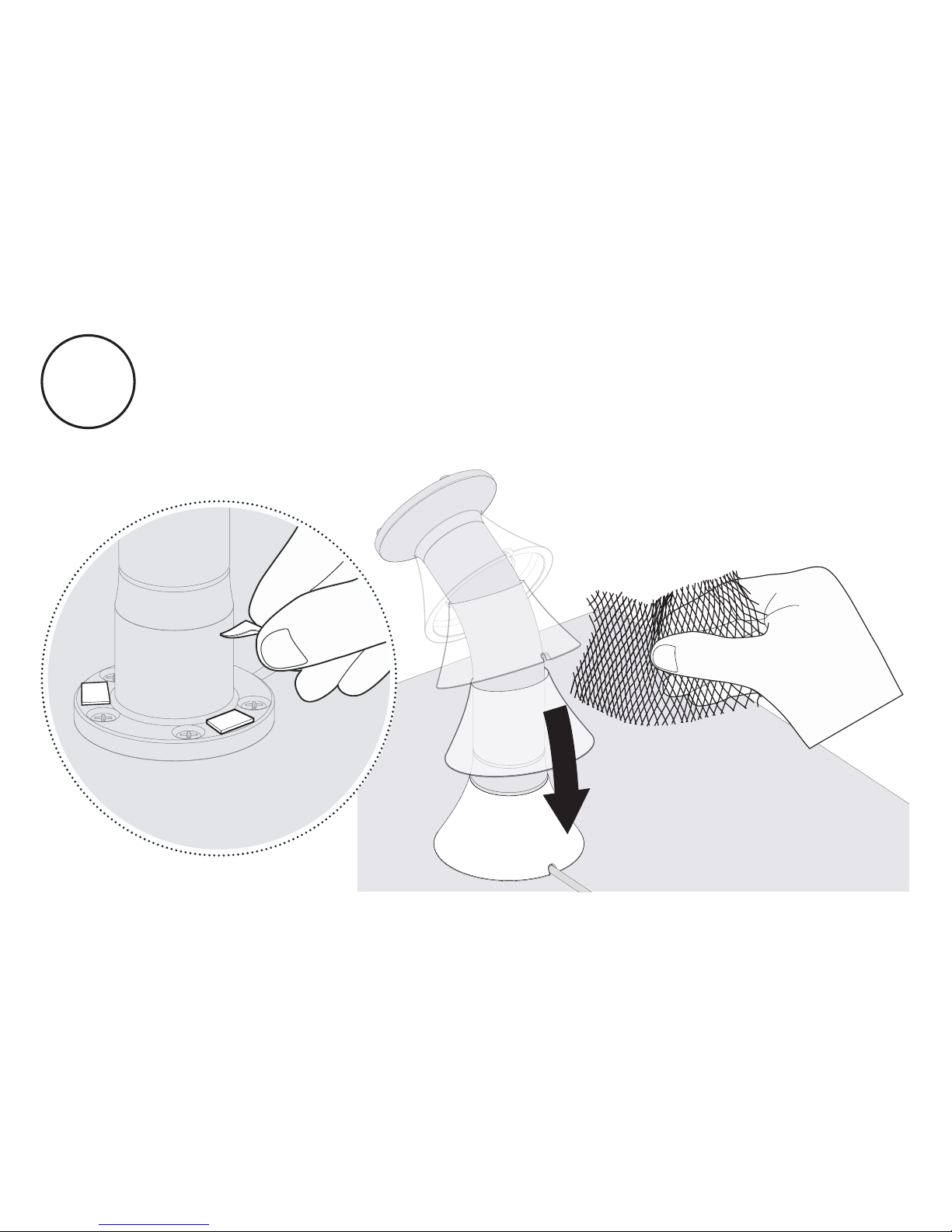
B12
Unpeel the adhesive pads on the Stalk Base and carefully
slide the Stalk Cover onto the Stalk Base. Tear off the
protective netting. Ensure that the Stalk Cover is securely stuck
down.
Page 46
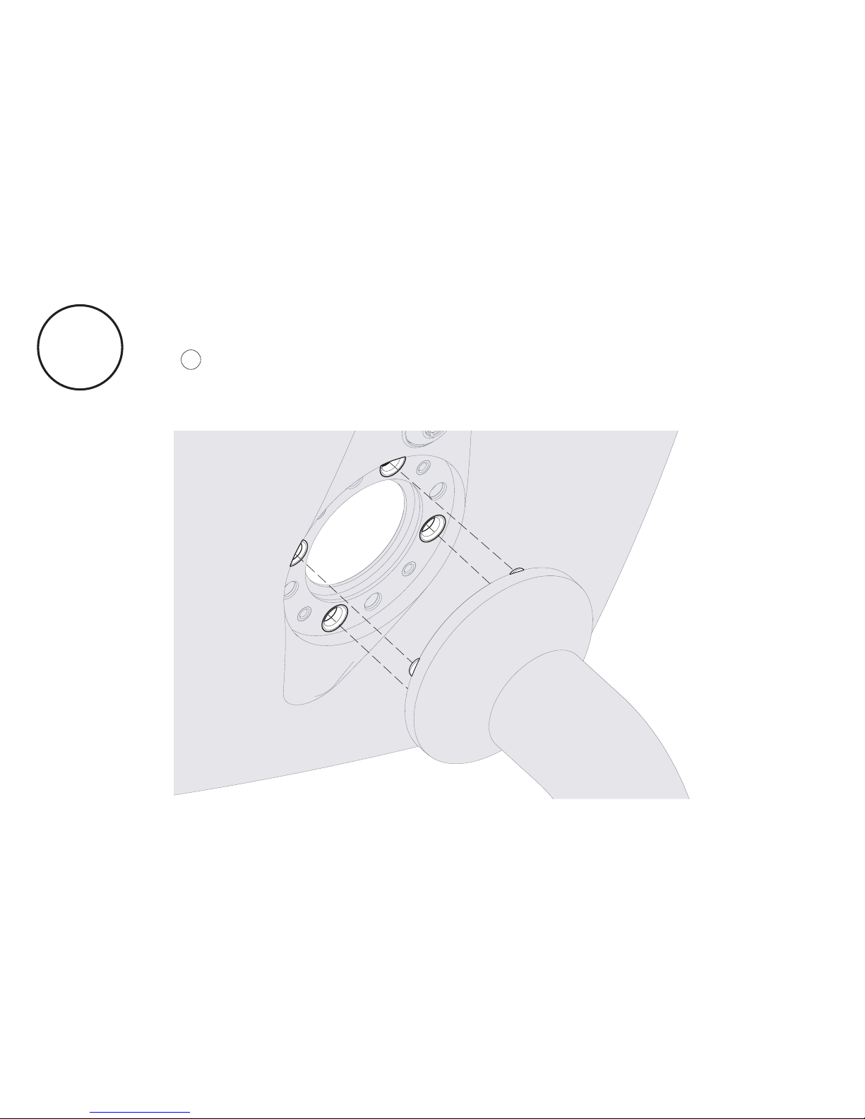
Locate the Sumo Case onto the Sumo Stalk using the metal
locating pins on the Sumo Stalk. Please refer to the guidelines
on to correctly configure the case orientation according to
your chosen switch configuration.
B13
B14
Page 47
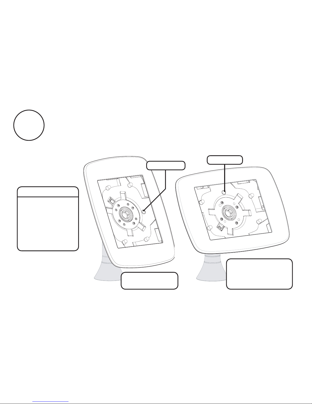
Follow the guidelines below to correctly orientate
your Sumo Case - appropriate to your specified Switch
Configuration and chosen Case Orientation.
B14
Lock at Top
Lock on Right
Portrait Orientation -
Switch Disabled
Hint:
Switch Configuration
means whether the
Neck of the Stalk
allows the screen to
rotate from portrait
to landscape, or if
the screen is locked
in a static position.
Landscape Orientation -
Switch Disabled
Switch Enabled
or
Page 48
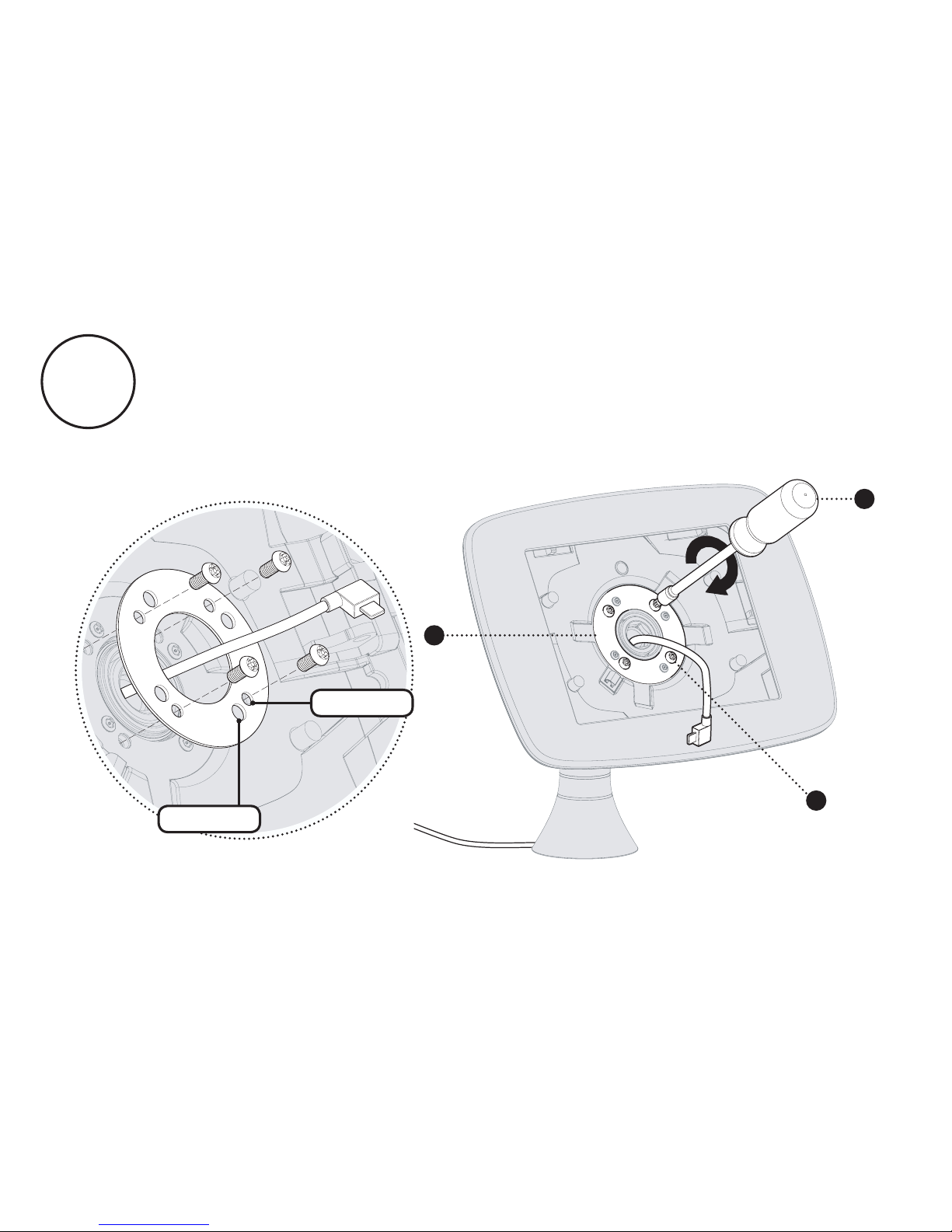
Feed the tablet cable through the Case Clamping Plate
and attach the Sumo case to the Stem. Ensure the metal Case
Clamping Plate is orientated correctly - it must sit flush with the
case. Tighten the screws to 2Nm or 1.5 ft-lb.
4
6
G
Small Hole
Large Hole
B15
Page 49
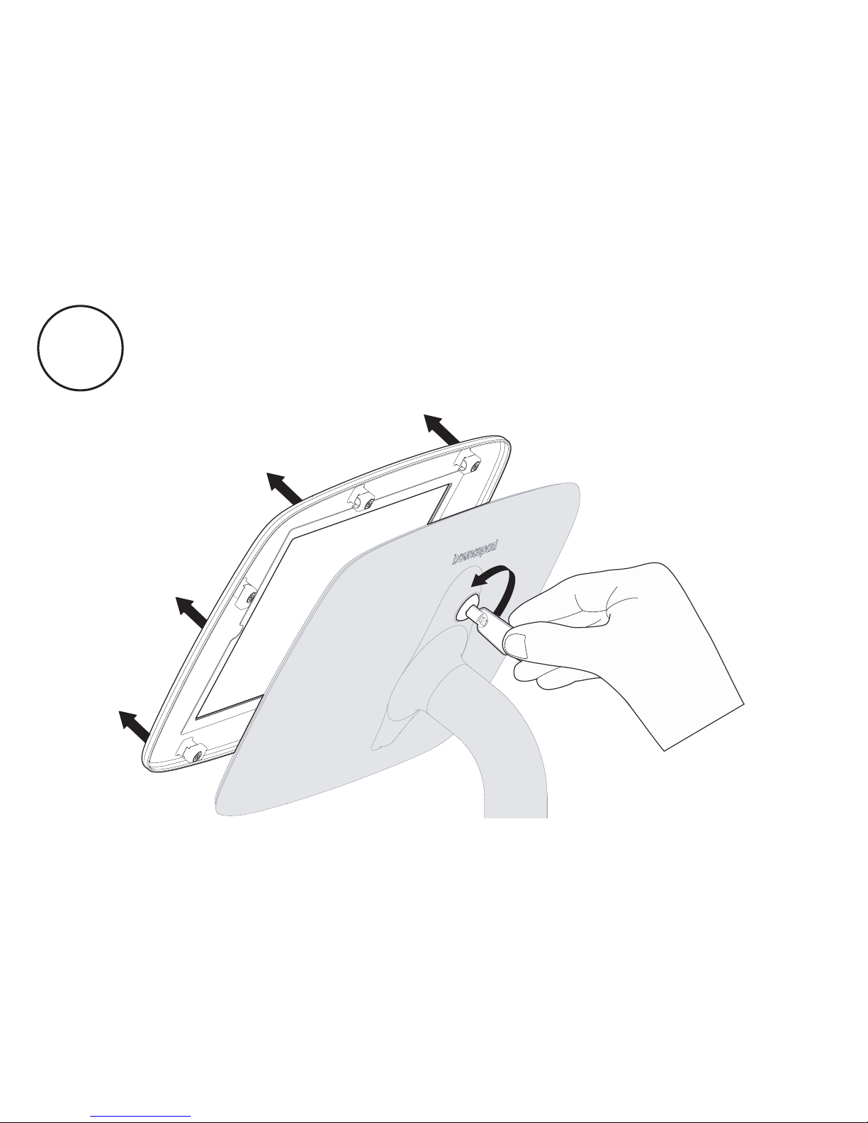
Unlock and remove the Sumo Faceplate.
B16
Page 50
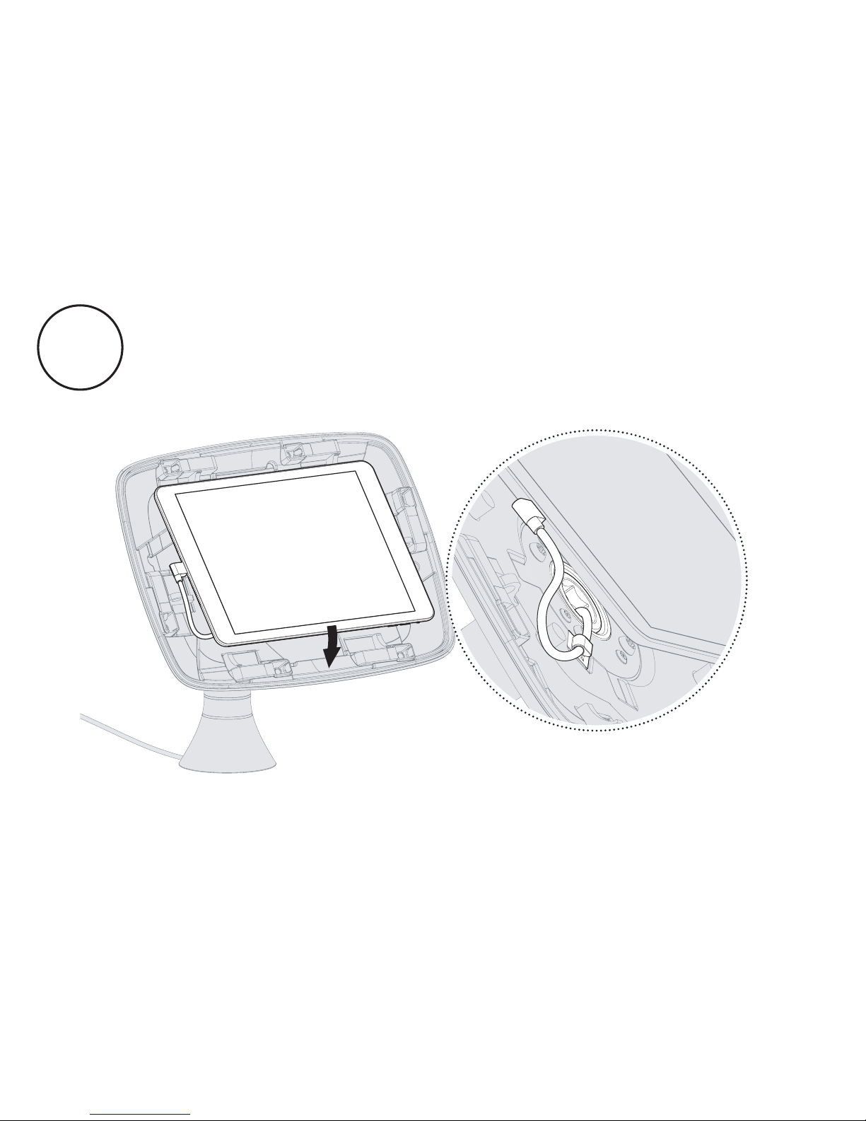
Connect the cable to your tablet and place into the secure
case. Your Sumo case is configured to house the tablet as
specified in your order. If you need to use a different tablet,
please contact us.
B17
Page 51
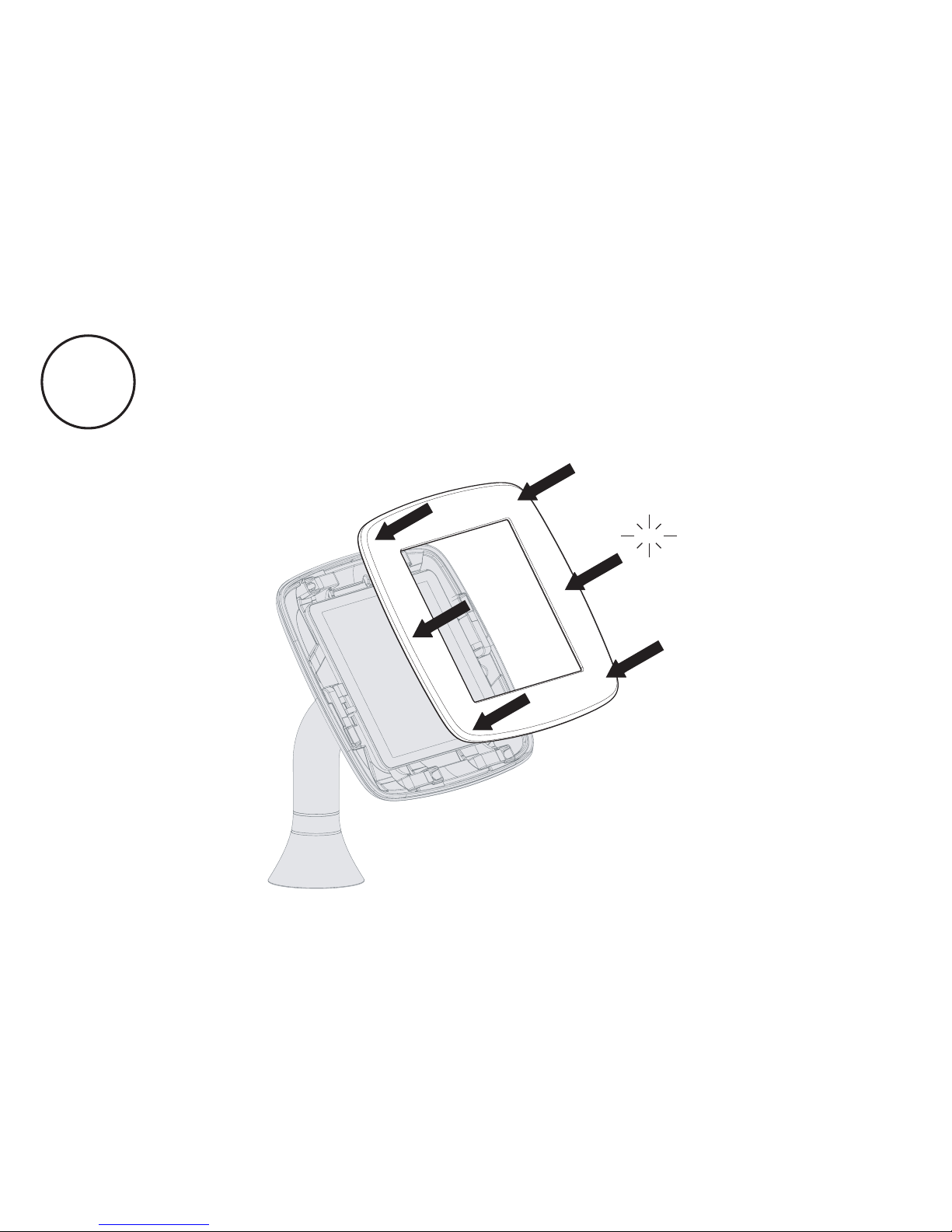
Attach the Sumo faceplate securely onto the main case
body. Press the faceplate onto the case - ensuring all edges are
locked securely in place.
B18
Click
Click
Page 52
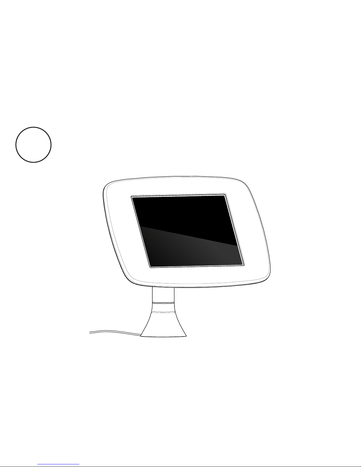
Finally, connect your tablet to its power source. You
have assembled your Sumo enclosure and it is now
ready for use.
B19
Page 53
If you have any queries, please
contact our Customer Care Team.
© 2015 Bouncepad Spotspot Ltd. All rights reserved.
www.bouncepad.com
 Loading...