

Page 1

Eco-System
Boiler
Boulter Boilers Ltd
Magnet House
30 White House Road
Ipswich
IP1 5JA
Tel: 01473 241555
Fax: 01473 241321
Manual Part No. PL 49021
Issue No 1
Date April 2002
Page 2

INFORMATION FOR THE INSTALLER AND SERVICE ENGINEER.
Under the Consumer Protection Act 1987 and the Health and Safety at Work Act 1974,
it is a requirement to provide information on substances hazardous to health (COSHH
Regulations 1988).
The Company takes every reasonable care to ensure that these products are designed
and constructed to meet these general safety requirements, when properly used and
installed.
To fulfil this requirement products are comprehensively tested and examined before
despatch.
This appliance may contain some of the materials below.
When working on the appliance it is the Users/Engineers responsibility to ensure that
any necessary personal protective clothing or equipment is worn appropriate to parts
that could be considered as being hazardous to health and safety.
INSULATION & SEALS
Glass Rope, Mineral Wool, Insulation Pads, Ceramic Fibre, Fibre Glass Insulation.
May be harmful if inhaled. May be irritating to the skin, eyes, nose or throat. When
handling avoid inhalation and contact with the skin or eyes. Use (disposable) gloves,
face masks and eye protection.
After handling wash hands and other exposed parts. When disposing, reduce dust with
water spray, ensure parts are securely wrapped.
GLUES, SEALANTS & PAINT
Glues, Sealants and Paint are used in the product and present no known hazards when
used in the manner for which they are intended.
KEROSENE & GAS OIL FUELS (MINERAL OILS)
1. The effect of mineral oils on the skin vary according to the duration of exposure.
2. The lighter fractions also remove the protective grease normally present on the
surface of the skin rendering the skin dry, liable to crack and more prone to
damage caused by cuts and abrasions.
3. Skin rashes (oil Acne). Seek immediate medical attention for any rash, wart or sore
developing on any part of the body, particularly the scrotum.
4. Avoid as far as possible any skin contact with mineral oil or with clothing contami-
nated with mineral oil.
5. Never breath any mineral oil vapours. Do not fire the Burner in the open i.e. out of
the Boiler as a miss fire will cause unburnt oil vapours.
6. Barrier cream containing lanolin such as Rosalex Antisolv, is highly recommended
together with a strict routine of personal cleansing.
7. Under no circumstances should mineral oils be taken internally.
HEALTH AND SAFETY
Due to a policy of continual development Boulter Boilers
reserves the right to alter or amend the design of its products without prior notice.
OFTEC Code of Practice OCP/1: 1995 For the Safe Installation, Commissioning, Maintenance and Fault
Rectification of Oil Firing Equipment should be consulted.
BOULTER BOILERS
Boulter Boilers Limited
Magnet House,
30 White House Road,
Ipswich IP1 5JA
Telephone: (01473) 241555
Fax: (01473) 241321
A member of the Bullough Group of Companies
Page 3

BOULTER BOILERS Eco-System PAGE 1
CONTENTS - Part 1
SECTION 1 - USER GUIDE
1:2 Safety Notices
1:5 Operating Instructions
1:5:1 Boiler Control Thermostat
1:5:2 Boiler Overheat/Limit Thermostat
1:5:4 Lockout Indicator
1:5:5 Starting your Boiler
1:5:6 Switching off Temporarily
1:5:7 Shutting Off for Summer
1:5:8 Sealed System Central Heating
1:5:9 Frost Protection
1:5:10 Oil Delivery
1:5:11 Maintenance/Troubleshooting Guide
1:5:12 Option Programmer
SECTION 2 - INTRODUCTION
2:1 Introduction
2:2 Flue Options
2:3 Commissioning
2:4 Safety
SECTION 3 - TECHNICAL DATA
3:1 Fuels
3:2 Boiler Technical Details
3:3 Burner Details
3:4 Electric’s
3:5 Dimensions
3:6 Commissioning Data
SECTION 4 - INSTALLATION
4:1 Standards and Regulations
4:2 The Heating System
4:3 Siting & Positioning
4:4 The Hearth
4:5 The Chimney
4:6 Air Supply
4:7 Oil Storage
4:8 Oil Supply
4:9 Oil Burner
SECTION 5 - BALANCED FLUES
5:1 Balanced Flue Boilers
5:2 Horizontal Balanced Flues
5:3 Vertical Balanced Flues
5:4 Positioning the Boiler
5:5 Terminal Guards
5:6 Horizontal Flue Terminal
5:7 Blanking Plates
SECTION 6 - BALANCED FLUE
INSTALLATION
6:1 Notes on Installation
6:2 Low Level Horizontal Flue
6:3 High Level Horizontal Flue
6:4 Vertical Flues
6:5 High Level Flue Length Alteration
6:6 Quick Fit Flue Systems
SECTION 7 - COMMISSIONING
7:1 Commissioning
7:2 Responsibility
7:3 Reporting
7:4 Recommended Commissioning Check
List
7:5 Recommended Commissioning Tests
SECTION 8 - MAINTENANCE
8:1 Maintenance
8:2 Air Shutter Adjustment
8:3 Baffle Arrangement
SECTION 9 - SPARES & ACCESSORIES
9:2 Boiler Spare Parts, 12/19 & 19/26
9:4 Burner Parts
SECTION 10 - FAULT FINDING
10:1 Fault Finding
10:2 Fault Finding Chart
Page 4

BOULTER BOILERS Eco-System PAGE 2
1:2 IMPORTANT SAFETY NOTES
To obtain the best possible performance and
trouble free operation from your Boiler, it is
important that you read these instructions carefully.
Your Eco Boiler has built-in safety features, which
are detailed in the relevant section of this manual.
1:2.1
The heating system must comply with the latest
editions of British Standard 5410 and The Building
Regulations.
Please note: It is essential in the interest of the
Boiler efficiency and reliable performance that
once the Boiler has been installed it is first
commissioned by a competent and preferably
an O.F.T.E.C.* registered engineer. It is the
responsibility of the installer to ensure that the
Boiler is commissioned.
If an engineer is not known, Boulter Boilers will
be pleased to provide details of commissioning
and servicing engineers from their register.
*The Oil Firing Technical Association for the
Petroleum Industry - Banstead, Surrey 01737
373311.
◆ If it is known or suspected that a fault exists on
the Boiler, it MUST NOT be used until the fault has
been corrected by a competent engineer (see
Failure to Start).
◆ It is essential that the instructions in this
booklet are strictly followed for safe and economic
operation of the Boiler. Failure to observe these
instructions may invalidate your right to free
breakdown cover during the guarantee period.
We recommend that you keep these instructions in
a place near your appliance for easy reference.
1:2.2 Air Supply to Boiler Conventional Flue
Where your Boiler is used on an open conventional
flue system, a permanent air supply is required for
combustion. Clearances provided at the sides and
rear of the appliance for air entry must be kept free
of obstruction. For further explanation please refer
to section 4.6 of this installation manual.
Your Eco Boiler should be connected to an
electrical supply complying with the Electrical
Wiring Regulations (BS7671): as well as an oil
supply complying with BS5410 Pt.1; and an
appropriate flue system.
◆ ALWAYS SWITCH OFF THE ELECTRICAL
SUPPLY before removing any of the covers for
cleaning.
◆ If any part of the Boiler or its flue is modified,
then the guarantee/warranty will be invalidated.
Page 5

1:5 OPERATING INSTRUCTIONS
1:5.1 BOILER CONTROL THERMOSTAT
The Boiler Control Thermostat is also the ON/OFF
switch for the Boiler. To Switch the Boiler off, turn
the Thermostat to the ‘OFF’ position and isolate at
the mains isolating switch.
The Boiler Control Thermostat also controls the
water temperature within the Boiler.
The recommended Control Thermostat settings are
as follows:
WINTER HEATING & HOT WATER No. 4
SUMMER HOT WATER ONLY No. 2
The Boiler Control Thermostat automatically
switches the Burner ON and OFF to maintain the
selected temperature. The Burner is lit by an
automatic ignition system and therefore there is no
pilot flame.
The Boiler should not be operated below 60°C as
this will cause corrosion which will reduce the life of
the Boiler (Summer position).
1:5.2 BOILER OVERHEAT/LIMIT THERMOSTAT
The Boiler is fitted with a safety overheat/limit
thermostat. This will interrupt the power supply to
the Boiler and shut it down completely in the
unlikely event of overheating.
Should this occur, wait for the Boiler to cool, and
then reset the thermostat by pressing the limit
thermostat reset button located at the rear of the
Control Panel.
If this problem still persists, turn off the Boiler and
consult your installer.
BOULTER BOILERS Eco-System PAGE 3
Page 6
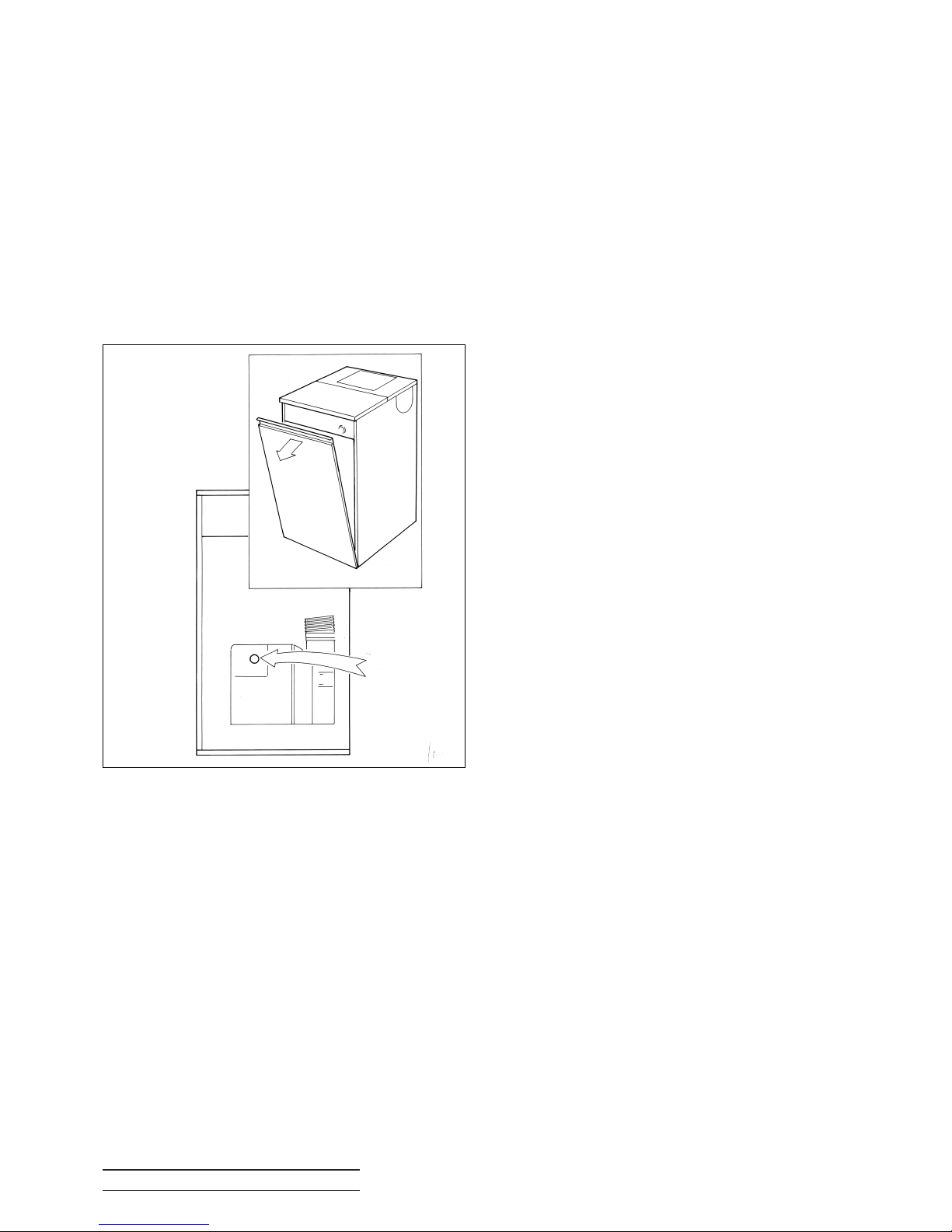
1:5.4 LOCKOUT INDICATOR
In the unlikely event of a Burner malfunction, it will
automatically shutdown, and the red lockout
indicator on the Control Panel will be lit.
To restart the Burner, wait for a period of at least 45
seconds. Remove the front door panel (as
illustrated) and press the lockout reset button
located on the front of the Burner (see fig 2). If the
Burner immediately goes to lockout again, wait
three minutes and then repeat the procedure, once
more only, by pressing the reset button again.
If this problem still persists, turn off the Boiler and
consult your engineer.
1:5.5 STARTING THE BOILER
1. Ensure that all external controls, e.g.
programmer, timer, room thermostat etc., are
turned on and calling for heat.
2. Make sure the Boiler Control Thermostat is set
within the recommended range 2 to 4 and that the
mains electricity and oil are turned on.
1:5.6 SWITCHING THE BOILER OFF TEMPORARILY
The Boiler may be stopped by turning the boiler
control thermostat to the OFF position on the
standard Control Panel, or the programme switch
to the OFF position on the optional programmer.
Alternatively, the Boiler may be stopped by:
1. Turning off the mains switch controlling the
Boiler, or
2. Turning the programmer (if fitted to the heating
system) to its off position.
1:5.7 SHUTTING OFF FOR THE SUMMER
If the Boiler is to be shut off for the summer, it is
advisable to have it thoroughly serviced. Thorough
cleaning will minimise corrosion during the idle
period. Remember, when the Boiler is required, to
ensure that the oil supply is open before switching
on.
1:5.8 SEALED SYSTEM CENTRAL HEATING
It is important that the correct operating system
pressure is maintained. Your Installer should give
guidance on this.
1:5.9 FROST PROTECTION
If there is any danger that your Boiler may freeze
up during severe weather conditions, it is
recommended that you consult your installer who
will be able to advise you on an appropriate course
of action, either by installing a frost thermostat or
the addition of system anti-freeze.
1:5.10 OIL DELIVERY
Where possible, it is advisable to temporarily
switch the Boiler off when your oil supply is being
replenished. This is to allow any sediment to settle
and not be drawn into the Boiler. If not this could
result in an inconvenient break down.
We advise that you keep your Boiler off for one
hour after the oil is delivered to your tank. Please
ask your supplier, or the driver to notify you before
the oil is discharged.
1:5.11 MAINTENANCE AND TROUBLE
SHOOTING GUIDE
1:5.11.1 MAINTENANCE
For normal cleaning of the outside casing, simply
wipe with a dry cloth. To remove stubborn marks
and stains, wipe with a damp cloth and finish off
with a dry cloth. DO NOT use abrasive cleaning
materials.
The Boiler must be serviced at regular intervals by
a qualified service engineer. Failure to have the
Boiler serviced at the recommended intervals will
BOULTER BOILERS Eco-System PAGE 4
Fig. 2
REMOVING
FRONT
DOOR
LOCKOUT
RESET
Page 7

invalidate the guarantee/warranty.
Using Kerosine Class C2 fuel, the Boiler should be
serviced at twelve monthly intervals to ensure that
the efficiency and performance of your boiler is
maintained.
Please also note that on conventional flue models,
it is possible for the air intake at the rear of the
Boiler casing to become blocked with household
debris.This air intake must remain clear at all times
and so it is advisable to inspect and clean this area
regularly. Please refer to section 1:2.2 in this
booklet.
Flue Terminal Pluming
Due to the high efficiency of the Eco range white
water vapour from the flue discharge - called
pluming may be observed from time to time under
certain weather conditions. This is perfectly normal
and should be no cause for concern.
1:5.11.2 FAILURE TO START
If the Burner fails to start, adopt the following
procedure:
1. Check that there is oil in the tank and that the
supply valve is open.
2. Check the programmer or time switch to
ensure that it is operating and set to the correct
time to be “ON”.
3. Check that the Boiler Control Thermostat is set
high enough to be “ON” or calling for heat.
4. Check whether the limit thermostat has tripped.
Press the reset button once the temperature has
dropped sufficiently.
5. Check whether the burner has gone to lockout
and the indicator lamp on the control box is lit.
Press the reset button on the Control box, when
released, the lights will go out and the Burner will
again attempt to start. If the Burner does not run
and again goes to lockout with red indicators
glowing:
◆ Wait three minutes.
◆ Repeat the procedure by pressing the button.
◆ Failure to start on the second attempt indicates
a fault requiring attention.
◆ Switch off the mains supply and call your
service engineer.
BOULTER BOILERS Eco-System PAGE 5
Page 8
2:1 INTRODUCTION
This Manual covers Installation, Commissioning
and Maintenance of the Eco Boilers.
The Eco boiler is:
1. Designed for Central Heating and Hot Water.
2. Not suitable for open vented systems.
3. Suitable for sealed Central Heating systems
which are within the maximum permitted working
pressure. All Boilers are supplied with a manual
reset limit thermostat.
4. Suitable for new installations and for replacing
existing boilers.
Eco Boilers offer greater freedom to select the
most suitable position for siting and the opportunity
to install the boiler in a suitable outbuilding if
required.
All models are supplied as standard with low level
horizontal firing Oil Burner, they are suitable for
connection to a conventional chimney or any of the
Camray 5 Balanced Flue options. Note: The nozzle
on this appliance is only covered by a 1 year
guarantee.
2:2 FLUE OPTIONS
Eco Boilers are designed to operate with high
efficiency, clean combustion and low noise level.
They offer unique versatility and can be used in the
following modes:
1. Low level rear outlet balanced flue.
2. High level rear outlet balanced flue.
3. Vertical outlet balanced flue. (Insulated
balanced draught chimney).
4. High level side outlet balanced flue.
5. For connection to a conventional chimney (via
conventional Flue Kit, 12/26 Part No. FC4CF).
6. Other options ma
y be available. Please contact
Boulter Boilers.
The tested balanced flue terminals and
connections afford an adequate supply of air for
combustion and equalisation of pressure between
exhaust and intake as required for operation under
unfavourable wind conditions.
Balanced flues are supplied in a carton which
includes ALL parts for balanced flue installation.
The horizontal terminals are designed to avoid the
possibility of staining outer walls through which
they pass.
2:3 COMMISSIONING
It is essential in the interest of boiler efficiency and
reliable performance that once the boiler has been
installed it is first commissioned by a qualified
engineer.
If an engineer is not known, Boulter Boilers will be
pleased to provide details of commissioning and
servicing engineers from their register.
See Section 7 for Commissioning Procedure.
It is the responsibility of the installer
to ensure that the boiler is
commissioned by a competent engineer,
preferably an OFTEC* Registered
Commissioning Engineer.
*The Oil Firing Technical Association for the
Petroleum Industry, Banstead, Surrey
☎ (01737) 373311.
2:4 SAFETY
READ HEALTH AND SAFETY INFORMATION
ON INSIDE FRONT COVER OF THIS MANUAL.
IMPORTANT
Should you wish to remove or
dismantle any covers or parts of the
boiler for cleaning or maintenance
ALWAYS FIRST SWITCH OFF THE
ELECTRICITY SUPPLY.
1. On no account should any part of the Boiler or its
Flue be modified with the exception of flues which
require adjusting to length to suit site conditions, as
detailed in this manual.
2. The wiring of the control panel should be as the
wiring diagrams included in this Manual. Wiring
should not be tampered with, modified or changed
for any reason.
3. Only use Boulter replacement parts.
Non compliance with the above will invalidate the
Guarantee.
BOULTER BOILERS Eco-System PAGE 6
IMPORTANT
IMPORTANT
Page 9
BOULTER BOILERS Eco-System PAGE 7
3:1 LIQUID FUELS
Eco Boilers will burn liquid fuels complying with BS2869 Part 2 1988 Class C2 as specified in the Code
of Practice for Oil Firing BS5410 Part 1.
Class C2 (Kerosine)
This fuel is suitable for all Eco models. Burners are supplied with the appropriate nozzle and pump
pressure as standard for this fuel. They are set for mid-range output. Details of all nozzle sizes and pump
pressure for all outputs are shown on section 3.6.
3:2 BOILER TECHNICAL DETAILS
Maximum Boiler working pressure 3 Bar - 30.6m Water Head
Minimum recommended return water temperature 60°C
Maximum hearth temperature less than 85°C.
Maximum side panel temperature less than 35°C above room temperature.
Minimum Conventional flue draught at boiler flue outlet 0.035”w.g. (8.75N/m
2
).
Maximum Conventional flue draught at boiler flue outlet 0.15”w.g. (37.5N/m
2
).
Water Resistance Less than 300 m.m.w.g.
with 11°C temperature rise across the
boiler.
3:3 BURNER DETAILS
Burner type - RIELLO 484T50, 483T50 or 487T50
Pressure Jet - supplied as standard. Manually
adjustable air regulator.
The burner must be set to details given in section
3.6.
For further details of the burner, refer to the burner
data sheets supplied in the literature envelope.
3:4 ELECTRIC’S
Electrical Supply 230v., 1 Ph., 50Hz.
The Electrical Installation of this
appliance must be performed by a
suitably qualified electrical
engineer/installer.
All wiring to supply and all system components
external to boiler must comply with the latest
edition of BS7671:1992 formerly IEE Wiring
Regulations.
This appliance must be effectively earthed and
connection to the supply must be through a double
pole isolating switch fused 5 amp.
The isolating switch must have all pole contact
separations at least 3mm
IMPORTANT
Page 10
BOULTER BOILERS Eco-System PAGE 8
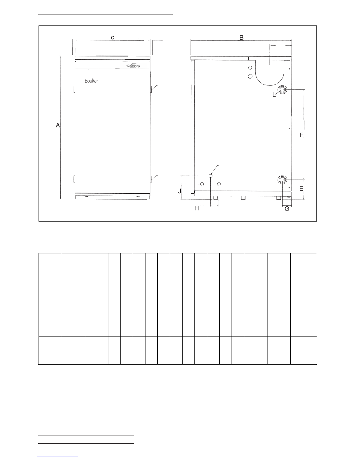
3:5 DIMENSIONS
Model
12/19
19/26
Output
kW
Btu/h
x 1000
11.7/
19
40/65
19/
26.4
65/90
ABCDEFGHJ
Flue
K*
L
mm mm mm mm mm mm mm mm mm
ø
insøins
860 596 446 130 121 540 55 65 92 4"
1
BSP
860 596 446 130 121 540 55 65 92 4"
1
BSP
Weight
Empty
Kgs
112
114
Water
Content
Filled
Weight
Kgs
130
135
Litres
17.5
21.0
* Conventional Flue Size
FLOW
CONNECTION
RETURN
CONNECTION
RETURN
CONNECTION
FLOW
CONNECTION
*15.00
*15.00
D
50.00
50.00 50.00
*
20mm ET KNOCKOUT
Page 11
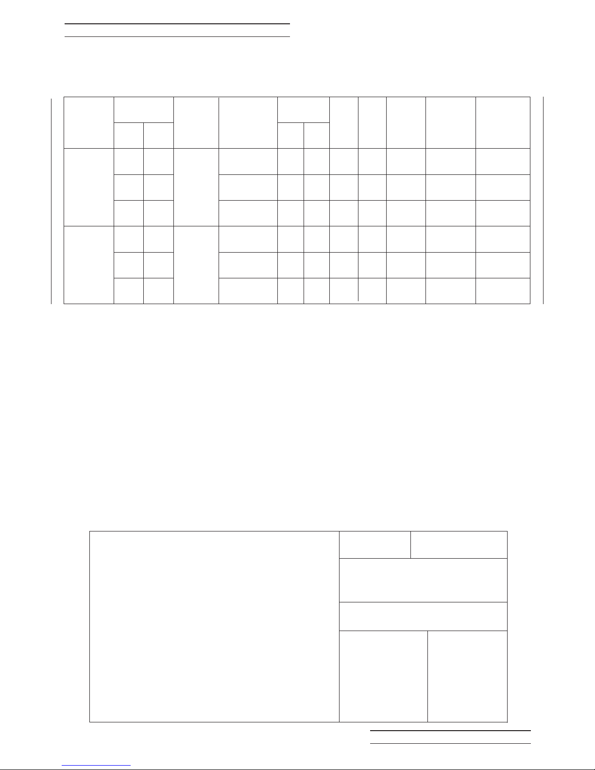
BOULTER BOILERS Eco-System PAGE 9
3:6 COMMISSIONING DATA
12/19 19/26
Maximum Temperature of Adjustable Controls Control Stat 85
o
C +/- 2oC
Limit Stat 110
o
C +0/-6oC
Maximum Emissions Limit (Class 1) NOx 250 mg/kWh-CO 125 mg/kWh
Range of Temperature Control Control Stat 0 - 85
o
C
Exit Flue Gas Mass Flow Kg/Sec x 10
-3
Heat Input (Full Load) kW (based on Net 22.1 29.0
efficiency of 91%)
Heat Output (Full Load) kW 19 26.4
1. There are two columns in the table for
combustion gas temperature:FLUE EXIT temperature, and
BOILER TEST POINT temperature.
2. Where possible CO2, smoke and flue gas
temperatures should be sampled from the FLUE
EXIT (i.e. external balanced flue discharge, or from
the test point provided in the conventional flue
adaptor)
3. These figures may be used to calculate
combustion efficiency.
4. Alternatively (where the forgoing is impractical
such as vertical BF) gases can be sampled at the
BOILER TEST POINT inside the casing.
Because the gas temperatures at this point are
significantly higher it should not be used to
calculate or measure efficiency.
5. If the BOILER TEST POINT temperature agrees
with the data in Table 3:6.1, then use the
appropriate FLUE EXIT temperature from the table
to calculate the combustion efficiency.
6. On conventional flue only - flue draught should
be measured at the flue exit test point.
3:6.1 Class C2, Kerosene Oil
RIELLO BURNER
Model
12/19
19/26
Output
Riello
RDB
TYPE
Nozzle
Danfoss
Delevan
US/GPH
Pump
Pressure
kW
Btu/h
x1000
11.7
16.1
19
19
23.4
26.4
40
55
65
65
80
90
0.4x60oES
0.5x60
o
ES
0.6x60
o
ES
0.6x60
o
ES
0.75x60oW
0.85x60
o
W
7.0
8.0
7.6
7.6
7.2
8.0
100
115
110
110
105
115
BAR psi
Boiler
Test Point
Temp oC
215-245
260-285
295-320
280
304
335
Flue Exit
Temp
o
C
Gross
165-195
180-225
180-245
180
200
204
Smoke
No.
C02
%
483T50
484T50
101.08
111.49
121.76
101.76
112.17
122.41
0-1
0-1
0-1
0-1
0-1
0-1
Fuel
Rate
Kg/h
LOW 6.69 9.61
MID 8.46 11.84
HIGH 9.24 12.79
Page 12

BOULTER BOILERS Eco-System PAGE 10
4:1 STANDARDS & REGULATIONS
The installation of the Boiler must comply with the
latest edition of :
BS 5410 Oil Installations
Pt 1 up to 44kW;
Pt 2 and over 44kW
BS 5449 Forced circulation hot water central
heating systems for domestic premises.
BS 4543 Pt. 1 & 3 Factory made insulated
chimneys.
BS 7593 Code of practice for the treatment of
water in domestic hot water central heating
systems.
BS 7671 (1992) Electrical Wiring Regulations.
BUILDING REGULATIONS.
Part J&L England and Wales
Part F Section III Scotland
Part L Northern Ireland
The Control of Pollution (Oil) Regulations
Oil boilers should be installed in accordance with
good practice as recommended by OFTEC (Ref.
2:3 Commissioning page 6).
4:2 THE HEATING SYSTEM
This should be installed in accordance with current
good practice as advised by HVCA. It is not the
purpose of the manual, nor is it possible, to
adequately deal with the subject in this manual.
When designing and installing the controls of the
heating system, it must be remembered that if the
control system is such that the water circulation
through the boiler can be totally or substantially
reduced whilst the oil burner can still fire, the water
in the boiler will reach very high or boiling
temperature before the boiler thermostat can
sense it and switch off the Burner.
If this condition is likely wire the controls so that the
electrical supply to the burner is switched off
simultaneously with the stopping of circulating
pumps or the closing of motorised valves.
On existing heating systems where a Boiler is
replaced, ensure that the system is chemically
cleaned.
The system should contain clean water and be free
from leaks. Suitable inhibitors against limescale
and corrosion should be added to the system.
Refer to BS 7593.
Kettling and system noises can be avoided by
suitable pre-treatment (i.e. Chemical Cleaning) at
the onset.This is essential when fitting a new boiler
to an existing system.
4:3 SITING & POSITIONING
The noise level from Eco boilers is quite low and
kitchen installations have not given rise to
complaints. Consideration must be given however,
to the following points.
1. Noise may be accentuated by the installation in
small rooms or recesses with hard or hollow stud
wall surfaces. Due consideration to the siting of
boilers should be given.
Further advice from BOULTER BOILERS should
be sought where any doubt exists.
2. Some individuals may be particularly sensitive to
even low noise levels and this should be discussed
before installation.
3. The type of chimney, position relative to the
boiler and whether a draught stabiliser is to be
fitted may affect sound level in the room.
4. The 12/19 & 19/26 Boiler models are serviced
from the front. A space of 450mm (18”) in front
should be available.
4:4 THE HEARTH
The Eco boilers have a Hearth Temperature of less
than 85°C. The boiler requires a level hearth on
which to stand which should comply with the
Building Regulations.
If the Boiler is to stand on a floor made of
combustible material then protection between the
Boiler and the floor should be provided by means
of non combustible material.
Consideration should be given to the Weight of the
Boiler and the Building Regulations regarding floor
loading.
The filled Boiler weight can be found in 3:5.
Advice should be sought from your local Building
Control Office if there are any doubts regarding the
floor supporting the Boiler.
Page 13
BOULTER BOILERS Eco-System PAGE 11
4:5 THE CHIMNEY - (FLUE Ø 4” OR 5”)
CONVENTIONAL CHIMNEY INSTALLATION ONLY.
VERY IMPORTANT
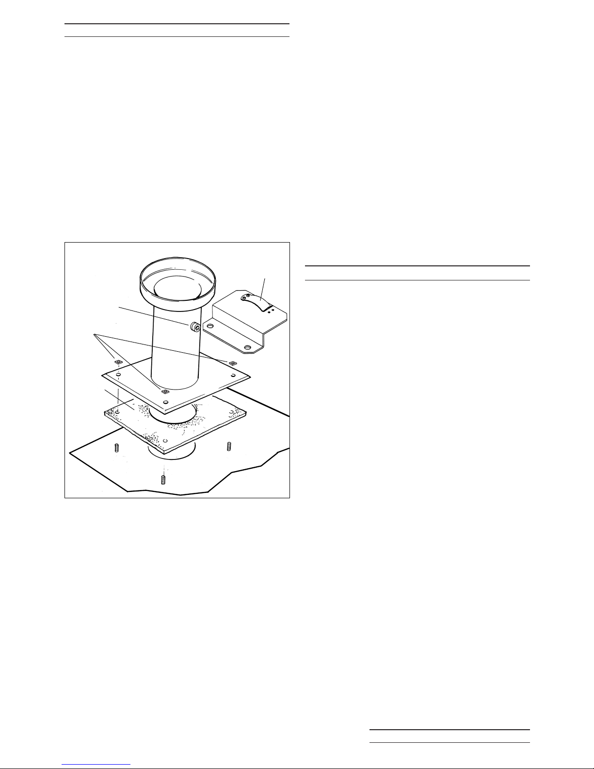
All Eco boilers are supplied in Balanced Flue
Form.
To connect either size of boiler to a
conventional chimney you must use The
Conventional Flue adaptor FC4CF.
This includes all parts necessary to make the
connection to the boiler. A test point is also
provided for ease of installation and
commissioning. Secure the air duct in the clip
provided.
The use of this adaptor is essential for safe
performance and is a condition of the
guarantee that this must be fitted.
The boiler requires a minimum stable draught of
0.1 mbar (0.04w.g.).
If the chimney exceeds 6m (20 feet) in length, it
may produce a draught exceeding 0.37 mbar
(0.15” w.g.) and a draught stabiliser should be
fitted.
The chimney should comply with the latest edition
of the Building Regulations and BS 5410: Part 1.
Factory built chimneys must comply with the
Building Regulations and BS 4543 Parts 1 and 3.
Compliance with the Building Regulations does not
indicate that the chimney is satisfactory in respect
of draught conditions, or is positioned so that ‘down
draughts’ will not occur.
Special pots and cowls which might restrict the flow
of gases must not be fitted and should be removed.
A brick chimney must be fitted with a suitable
stainless steel liner. Insulation between the liner
and an exposed chimney may be necessary to
avoid condensation.
A flexible liner should be the same diameter as the
Flue Offtake size of the boiler - 4”(100mm) or 5”
(125mm). (see page 8)
The Flue pipe, connecting the boiler to the chimney
adaptor should be the same diameter as the Boiler
Flue Offtake and should not be more than 1.8m
(6’-0”) long. Flue Pipes when fitted should satisfy or
be ‘deemed to satisfy’ the Building Regulations.
Flue pipe bends - 90° bends must not be used use 135° bends. Bends with soot doors should be
used where necessary
FOR BALANCED FLUE INSTALLATIONS SEE
SECTION 6.
4:6 AIR SUPPLY
CONVENTIONAL CHIMNEY INSTALLATION ONLY
A permanent adequate supply of air is required for
combustion and correct operation of a draught
stabiliser, if fitted.
This air enters the Boiler through the back panel. At
least 15mm clearance is required at the rear of all
boilers.
When the boiler is situated in a confined space or
chamber a permanent adequate supply of air is
required for ventilation to prevent over heating.
4:6.1 Opening Sizes
The clear opening required for combustion only
should be based on a requirement of 550mm
2
/kW,
(or 1in
2
per 4000 Btu/h) above 5kW
When a draught stabiliser is fitted to the flue pipe
or chimney in the room in which the boiler is
situated the clear air intake should be
1100mm
2
/kW.
When the boiler is situated in a confined space with
Combustion or Ventilation air from outside - Allow
550mm
2
/kW at low level and in addition
550mm
2
/kW at high level;
When Combustion and Ventilation air is taken from
a heated adjoining space the allowance should be
1650mm
2
/kW at low level and in addition
1100mm
2
/kW at high level. Ensure that the heated
adjoining space itself has an adequate supply of
air.
When the Boiler is installed in a basement or low
level boiler house where air can enter only from
high level, the incoming air supply for Combustion
and Ventilation should be ducted to low level. A
high level outlet should be provided for ventilation.
Gasket
(foil face
up)
Test Point
Air Duct
Securing Clip
Nuts
Conventional
Flue Adaptor
Fig 3
Page 14

BOULTER BOILERS Eco-System PAGE 12
4:7 OIL STORAGE
4:7.1 Oil Tank
Consideration to the access by fuel delivery lorries
should be given when positioning the oil tank.
Tank positioning should be in accordance with BS
5410 Part 1 and OFTEC Technical Book 3.
In the interest of most economical deliveries the Oil
Tank should be of 3,000 litres (600 gallons)
capacity.
It should be complete with the following:
1. Sludge Cock - on steel tanks.
2. Outlet Valve.
3. Contents Indicator.
4. Screw fill connection and independent vent. The
Fill and Vent should be suitably capped to prevent
ingress of water or fitted with return bends.
4:7.2 Steel Tanks
Tanks should be mounted on suitable supports, if
these are of brick or blocks, a damp proof
membrane should be inserted between the tank
and its supports.
Tanks should slope 20mm per 1m of length
downwards from the Oil Outlet to the Sludge Cock
situated at the opposite end.
4:7.3 Plastic Oil Tanks
Tanks made from plastic are now available. These
should be UV stabilised for protection against
sunlight, and coloured green. Plastic tanks do not
need to stand on piers, but should be supported
across the entire base area, ideally on 50mm thick
garden slabs or a concrete base. As there is only
one tapped outlet they are more suited to single
pipe feed as gravity supply or with a Boulter 3K Oil
Loop Deaerator where suction lift is required. (Part
No. BS 03060)
4:8 OIL SUPPLY
The oil entry holes in the boiler casing are shown
in the diagram in Section 3:5 of this manual.
Flexible Hoses supplied with the Boiler MUST NOT
pass through these holes.
All joints in the Oil Lines must be oil tight and the
Oil Line should be flushed clean before connecting
to the burner.
Note that no soldered joints are permissible in the
oil line.
4:8.1 Oil Filter
An Oil Filter is supplied with the Boiler.
Connections are 1/4 BSP Female, see fig. 4:8c.
It is essential for reliable operation that the Oil
Filter is fitted in the Oil Pipe supplying Oil from
the Tank to the Burner. It should be fitted as
close to the Boiler as practicable, but NOT
inside the Boiler casing.
It is a condition of the guarantees that the Filter
is fitted correctly.
4:8.2 Fire Check Valve (Not Supplied)
A Remote acting FIRE VALVE* must be fitted in the
suction line at the time of installation - see BS
5410: Part 1.
The valve must be fitted external to the Boiler,
preferably at point where the Oil Pipe enters the
building. The sensor should be located above the
Burner in the clip provided, see figs. 4:8b, 4:8d
& 4:8f.
The entry point for the Fire Valve Sensor should be
through any of the 20mm ET knockouts located at
the top of the rear casing, or side panels.
To prevent damage to the capillary always pass the
sensor through the blind grommet (supplied), it will
be necessary to cut across the diaphragm.
*Remote Acting Fire Valves are available from
Boulter, through your merchant or installer e.g.
Ref: Operating Capillary
Temperature Length
RAF9015C 90
o
C 1.5m
RAF9030C 90
o
C 3.0m
RAF9060C 90
o
C 6.0m
RAF9090C 90
o
C 9.0m
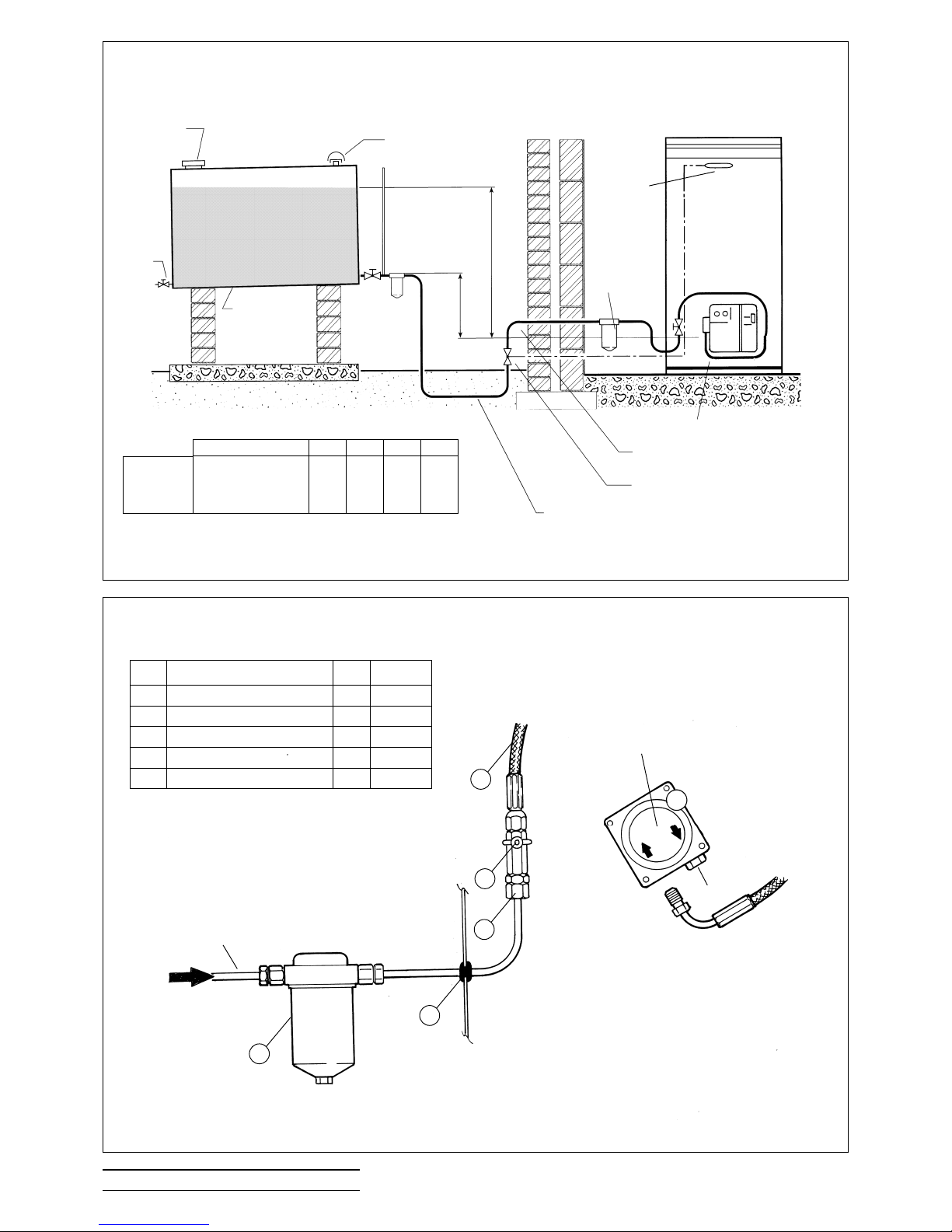
4:8.3 Single Pipe System
Fig. 4:8b
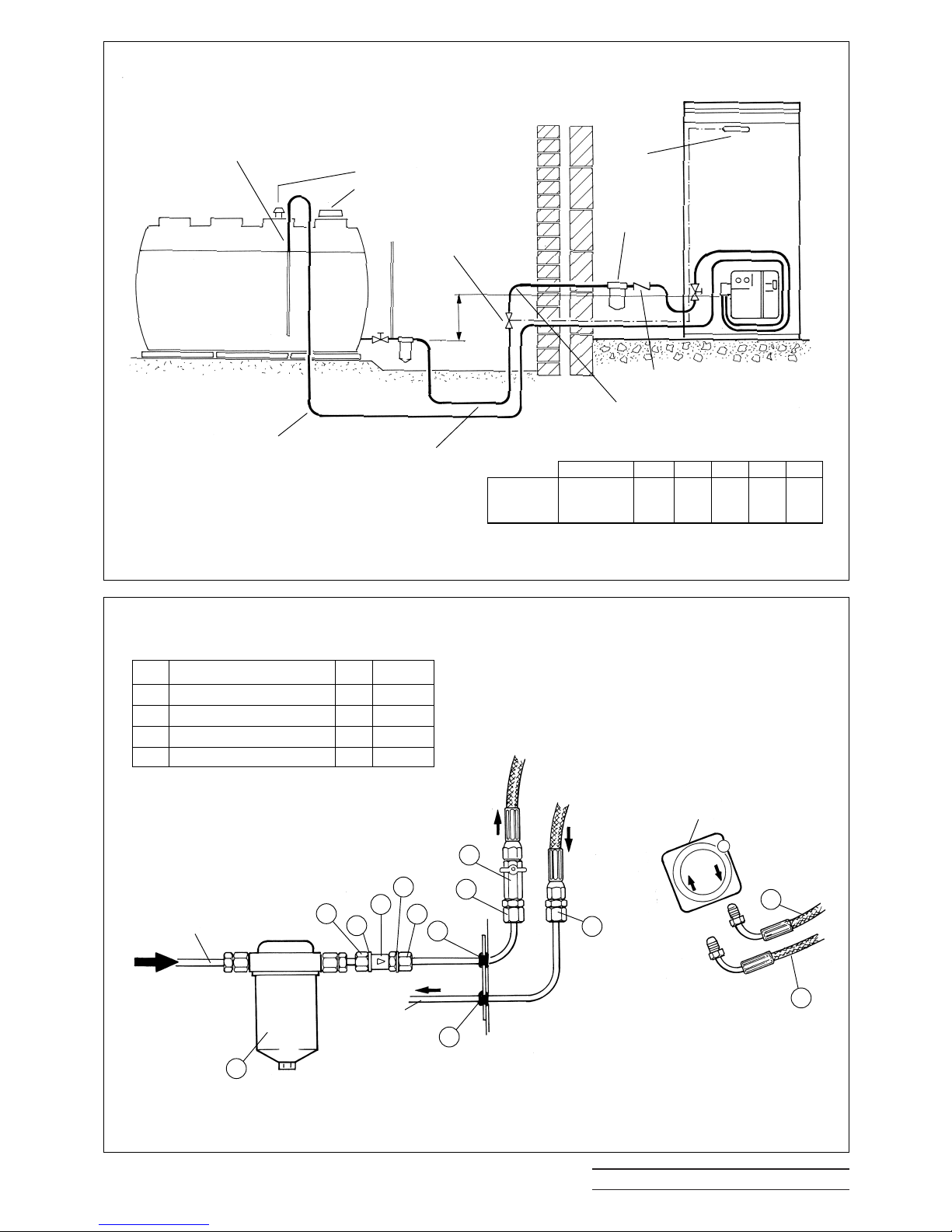
If the bottom of the Oil Tank is above the oil Burner,
install a 10mm copper supply pipe to the Burner
incorporating the correct Filter, Shut Off Valve and
Fire Check Valve.
Ensure that the Burner Oil Pump is correctly set for
‘Single Pipe’ operation. (See 4:9.2).
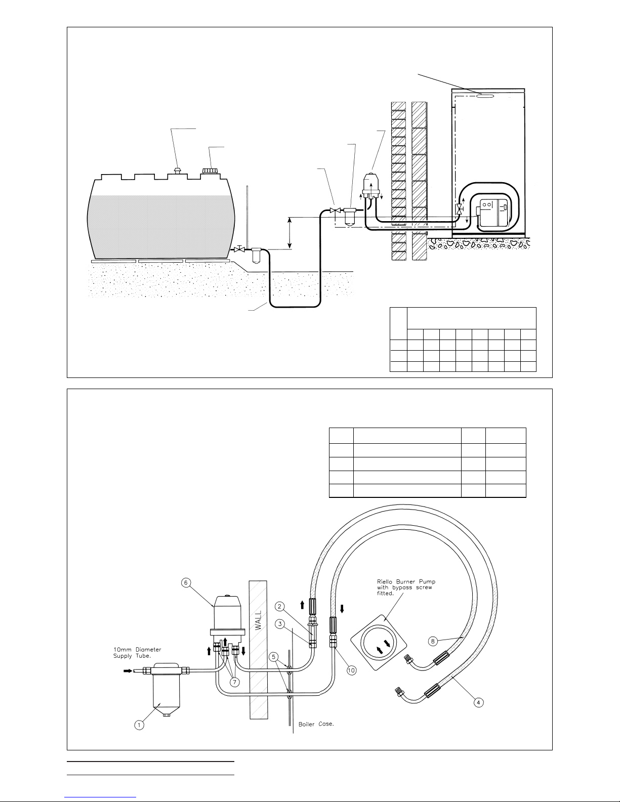
4:8.4 Two Pipe System
Fig. 4:8d
When the bottom of the Oil Tank is below the level
of the Oil Pump on the Burner it is necessary to
install an additional 10mm return pipe.
The Oil Filter, Shut Off Valve, spring loaded NonReturn Valve and Fire Check Valve are always in
the suction line supplying oil from the Tank to the
Burner.
The Non-Return Valve must be fitted to allow the
Page 15
BOULTER BOILERS Eco-System PAGE 13
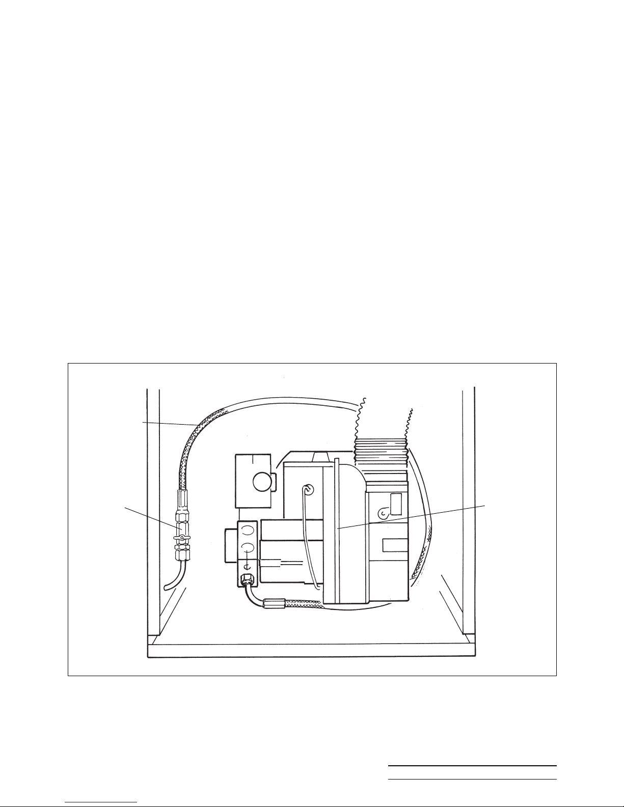
Fig. 4.8a
Flexible Oil Pipes and Fire Check Valve
Flexible Hose
Ball Valve Burner
flow in the correct direction and prevent drain back
to the Tank, see fig. 4:8e.
Ensure that Valves are NOT fitted in the Return
Line. The Return Line must be unobstructed at
all times.
Ensure that the Burner Oil Pump is correctly set for
‘two Pipe’ operation. (See 4:9.1)
4:8.5 Deaerator Oil Pipe System
Fig. 4:8f
An alternative two pipe arrangement can be
achieved using a 3K-Oil Loop Deaerator which
removes the air from the oil feed on a single pipe
lift. The Burner Pump is piped to the Deaerator,
which should be positioned close to the burner, but
NOT inside the Boiler Case. A Non-Return Valve
is not required in the return line.
The advantage of this system is gained where a
two pipe run from the oil supply tank is long or
difficult to achieve.
Boulter 3K Deaerators are available as an optional
extra from your merchant (Part No. BS 03060).
4:8.6 Water Separator Oil Filter
For changeover applications, the use of a Water
Separator Oil Filter, available from BOULTER
BOILERS is recommended (BS03052).
4:8.7 Flexible Oil Pipes
The Flexible Oil Pipes are fitted inside the Boiler
casing and are of adequate length to enable the
Burner to be removed without disconnecting.When
fitted correctly the pipes should be curved round
the Burner as shown in Fig.4:8a.
Page 16
BOULTER BOILERS Eco-System PAGE 14
OIL CONNECTIONS SEE BELOW
FIRE CHECK VALVE
ALTERNATIVE FILTER POSITION
TOTAL PIPE LENGTH ‘L’
FIRE
CHECK
VALV E
SENSOR
FILTER
SLUDGE
COCK
OIL TANK
SCREW
FILL
20mm / metre
FALL
INDEPENDENT
VENT
H
4 Metres MAXIMUM
SINGLE PIPE OIL SYSTEM - TANK OUTLET ABOVE BURNER
DO NOT FIT PUMP BYPASS SCREW TO BURNER - SEE 4.9.2
H METRES 0.5 1.0 1.5
2.0
Burner to supply 20 40 80 100
KEROSENE
10mm OD
PIPE
TABLE GIVING MAXIMUM PIPE LENGTH 'L' METRES
Fig. 4:8b Single Pipe Oil System.
RIELLO BURNER PUMP
NO BYPASS SCREW
FITTED
SINGLE PIPE OIL SYSTEM - OIL CONNECTIONS
Items 1 - 5 NOTsupplied with Boiler
ITEM PART QTY CODE
1 Filter 25I 1 BS 00496
2 Ball Valve 1 BS 03041
31/4'' BSP x 10mm Coupling 1 FS 00151
4 Longlife Hose 900mm 1 BS 03101
5 Grommet 3 RP00610
BOILER CASE
10MM DIAMETER
SUPPLY TUBE
LH & RH FUEL ENTRY AVAILABLE (LH SHOWN)
SCHEMATIC DIAGRAM FIT HOSE AS SHOWN IN FIG. 4:8a
PLUG
Fig. 4:8c Schematic Oil Pipe Connectors
Camray 5
Camray 5 Utility
1
5
4
3
2
Page 17
BOULTER BOILERS Eco-System PAGE 15
RETURN PIPE
NON RETURN VALVE
ALTERNATIVE FILTER POSITION
SUCTION PIPE ‘L’ MAX
FIRE
CHECK
VALV E
SENSOR
FILTER
OIL TANK
SCREW FILL
INDEPENDENT VENT
H
TWO PIPE OIL SYSTEM - TANK OUTLET BELOW BURNER
FIT PUMP BYPASS SCREW TO BURNER
FIRE CHECK
VALV E
SAW CUT OR SMALL
HOLE IN RETURN PIPE
INSIDE TANK TO
PREVENT SYPHON
H METRES 0.5 1.0 1.5
2.0
Burner to 100 100 90 70
supply
KEROSENE
10mm OD
PIPE
TABLE GIVING MAXIMUM PIPE LENGTH 'L' METRES
Fig. 4:8d Two Pipe Oil System.
RIELLO BURNER PUMP
WITH BYPASS SCREW
FITTED
TWO PIPE OIL SYSTEM - OIL CONNECTIONS
Items 1 -5 are supplied with the Boiler. See Fig 4:8c.
BOILER CASE
10MM DIAMETER
SUPPLY TUBE
LH & RH FUEL ENTRY AVAILABLE (LH SHOWN)
SCHEMATIC DIAGRAM FIT BOTH HOSE AS SHOWN IN FIG 4:8a
10MM
DIAMETER
RETURN
TUBE
Fig. 4:8e Schematic Oil Pipe Connectors
Items 6 -10 NOT supplied with boiler.
ITEM PART QTY CODE
6 Non Return Valve 1 BS 00538
8 Longlife Hose 900mm 1 BS 03103
9 Washers 2 FS 00159
10
3
/8'' BSP x 10mm Coupling 3 FS 00157
Camray 5
Camray 5 Utility
1
5
4
8
5
3
2
10
10
9
6
9
10
0
100
Page 18
BOULTER BOILERS Eco-System PAGE 16
3K OIL DEAERATOR MUST BE
INSTALLED UPRIGHT OUTSIDE
BUILDING
DO NOT FIT NON-RETURN VALVE
TOTAL PIPE LENGTH
FIRE CHECK VALVE SENSOR
FILTER
OIL TANK
SCREW FILL
INDEPENDENT VENT
H
DEAERATOR OIL SYSTEM - TANK OUTLET BELOW BURNER
FIT PUMP BYPASS SCREW TO BURNER
FIRE CHECK
VALV E
Fig. 4:8f. Deaerator Oil Systems
DEAERATOR PIPE OIL SYSTEM - OIL CONNECTIONS
LH & RH FUEL ENTRY AVAILABLE (LH SHOWN)
SCHEMATIC DIAGRAM FIT BOTH HOSE AS SHOWN
IN FIG 4:8c
Fig. 4:8g Schematic Oil Pipe Connections.
ITEMS 7, 8, & 10 ARE AVAILABLE AS A KIT NO. BS 03058C.
The table right shows total Pipe Length ‘L’ metres
0 0.5 1.0 1.5 2.0 2.5 3.0 3.5
6 242119161311 8 6
8 100 100 93 84 71 59 46 33
10 100 100 100 100 100 100 100 100
Pipe
Size
mm
O/D
Lift - H metres (3.5m Max)
3K OIL
DEAERATOR
ITEM PART QTY CODE
6 3K Oil Loop 1 BS 03060
7
1
/4'' BSP x 10mm Coupling 3 FS 00151
8 Longlife Hose 900mm 1 BS 03103
10
3/
8
'' x 10mm Coupling 1 FS 00157
Camray 5
Camray 5 Utility
Page 19
BOULTER BOILERS Eco-System PAGE 17
4:9 OIL BURNER
The Burner makers’ technical leaflet is supplied
with this manual and provides supplementary
information not included in this manual.
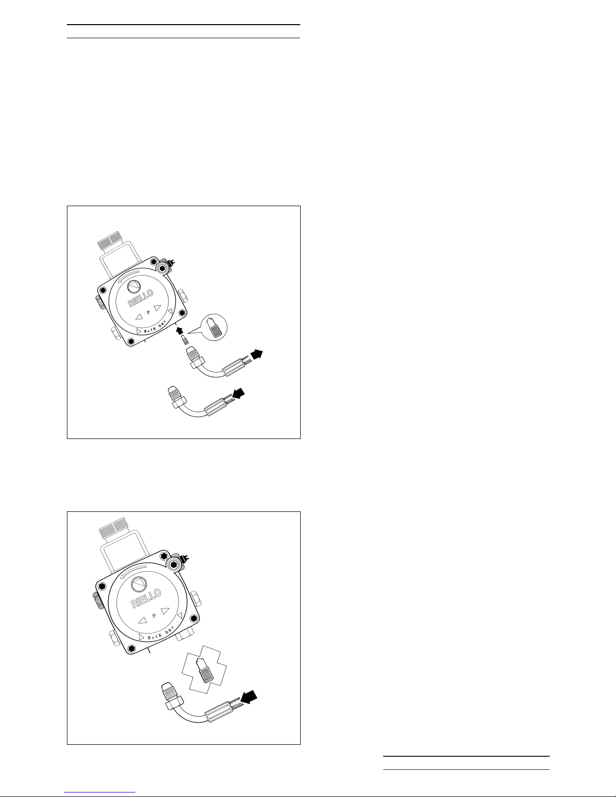
4:9.1 Burner Pump for Two Pipe and Deaerator
System
For two pipe oil systems the Burner Oil Pump has
to be fitted with the Bypass Screw supplied. Boilers
are despatched with the Bypass Screw in a
labelled envelope attached to the Burner. This
socket screw is inserted into the return port as
shown in Fig. 4:9a.
4:9.2 Burner Pump for Single Pipe System
The burner is supplied set for single pipe operation.
The return port is plugged and the Bypass Screw
is not fitted. See Fig. 4:9b.
Fig. 4.9a Burner Pump for Two Pipe Operation
Fig. 4.9b Burner Pump for Single Pipe Operation
ONLY USE BYPASS SCREW FOR ALLEN KEY (2.5MM).
DO NOT USE SLOTTED SCREW
ALLEN KEY
BYPASS
SCREW
FLOW
RETURN
FLOW
BYPASS SCREW
NOT REQUIRED
RETURN PLUGGED
Page 20

BOULTER BOILERS Eco-System PAGE 18
5:1 BALANCED FLUE BOILERS
A range of Balanced Flue Kits are available as
optional extras.
Balanced Flues permit considerable choice of
siting of the Boiler. Boilers may be installed in
situations where no chimney exists, where the
chimney is unsatisfactory or in outhouses.
It is important that care is exercised in
choosing a suitable location for the Boiler and
Flues. It is to be expected that with the help of
this manual and the application of caring
engineering experience and common sense
unreasonable liberties will not be taken.
It is a mandatory requirement that:-
1. The terminals of balanced flues which can be
touched are to be fitted with a guard.
Any proposed installation which deviates from the
details provided or gives rise to any doubt should
be referred to BOULTER BOILERS LTD. who will
be pleased to consider and discuss it.
5:1.1 Balanced Flue Types
Three types are available
1. Low Level Horizontal - Rear & Side
- Discharge L/R
2. High Level Horizontal - Rear & Side
- Discharge L/R
3. Vertical (Flat or Pitched Roof)
Only Kerosine fuel may be used when the Low
level Horizontal flues are installed.
5:2 HORIZONTAL BALANCED FLUES
The Terminals of Horizontal Balanced Flues should
be installed on a plain surface of wall preferably not
less than 900mm from internal corners of the
building and away from any recesses and any
projections on the wall face that could affect wind
flow across it.
Listed are the general restrictions as to the
positioning of Horizontal Balanced Flue Terminals.
Refer to Fig 5:4a
1. Positions should be avoided where the exhaust
of combustion products could cause nuisance.
2. Terminals must be situated more than 600mm
distance from any opening in the building.
3. Avoid close proximity to internal corners where
products of combustion may not freely disperse
and may enter the air intake to the boiler.
4. Avoid positions such as narrow passageways,
especially with a closed end, where easy
dispersion could be adversely affected.
5. Avoid positions where the terminal may be
discharging close to and in the direction of a near
neighbouring dwelling or exhausting immediately
over adjoining property.
6. Avoid positioning immediately under openable
windows.
7. Care should be taken to ensure that there is
clearance between the outer surface of the flue and
any combustible material.
8. Positioning the Flue terminal within a CAR
PORT is not recommended.
5:3 VERTICAL BALANCED FLUES
Vertical Balanced Flues enables boilers to be
installed in single storey outhouses or utility rooms
where it may not be convenient for it to be sited
near an outer wall. It may also be employed to
exhaust vertically to avoid nearby windows or
doors.
Vertical Balanced Flues may also be preferred in
cases where close proximity to adjoining houses or
property dictates minimum exhaust noises.
5:3.1 Positioning of Vertical Flues
Listed are general restrictions as to the positioning
of Vertical Balanced Flues. Refer to Fig. 5:4a.
1. Avoid positions where Vertical Flues will exhaust
adjacent to a higher wall.The minimum distance for
operation from a higher vertical wall must be
600mm.
2. Ensure Vertical Flues do not exhaust below the
level of any openable window less than 2300mm
horizontally from the terminal (see BS 5410:1).
3. Care should be taken to ensure that there is
clearance between the outer surface of the flue and
any combustible material.
Page 21
BOULTER BOILERS Eco-System PAGE 19
5:4 POSITIONING THE BOILER
Read Sections 5:2 & 5:3
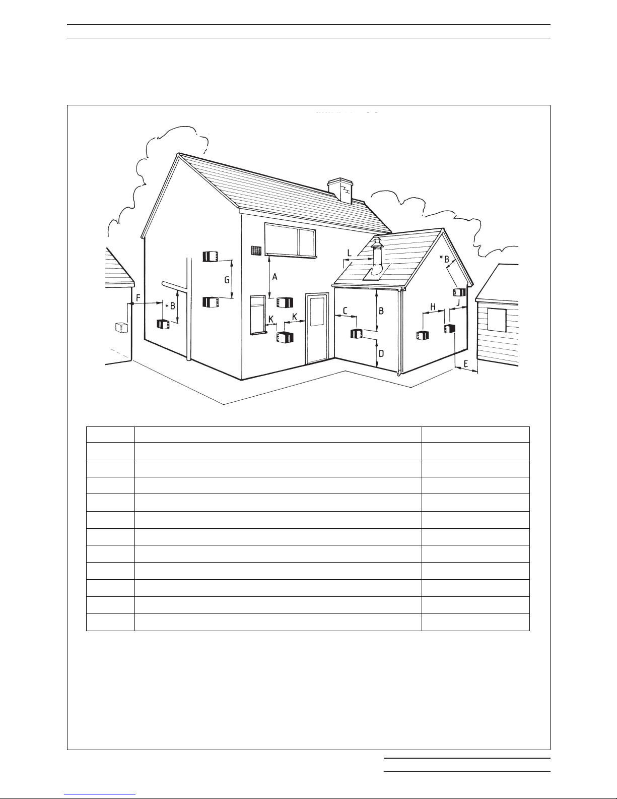
Some combustion noise occurs at the Exhaust Terminal of Balanced Flues and care should be exercised
to ensure that the position of the exhaust is not near doors or opening windows of the house it serves, or
doors or windows of any neighbouring house. See Fig. 5:4a.
Fig. 5.4a Balanced Flue Terminal Positions
REF DESCRIPTION DISTANCE IN MM
A Directly below an Opening, Air Brick or Window 600
B Below a Gutter, Sanitary Pipework or Eaves 75 (600*)
C From any Internal Corner 300 (900)
D Above Ground 300 (600)
E From a surface facing the Terminal 600 (1200)
F From a Terminal facing a Terminal 1200
G Vertically between Two Terminals on the same wall 1500
H Horizontally between Two Terminals on the same wall 750 (1200)
J From any External Corner 300 (600)
K
Horizontally from any Opening, Air Brick, Window or Door
600
L Vertical Flue from Wall (Flat or Pitched Roof) 750
Table to above Flue Terminal Positions - MINIMUM dimensions
*Where the terminal is within 1m of any plastic material, such material
should be shielded from the effects of the combustion products of the flues
NOTE:- Whilst the dimensions in BS 5410 are shown in the table, it is stressed that possible variances
in local site conditions may not always be obvious and that if in any doubt the dimensions in brackets
should be observed.
BOULTER BOILERS would be pleased to advise on any difficult positioning
RECOMMENDED FLUE TERMINAL POSITION
Terminals should be so positioned as to avoid products
of combustion entering opening into buildings or other
flues or vents.
Page 22
BOULTER BOILERS Eco-System PAGE 20
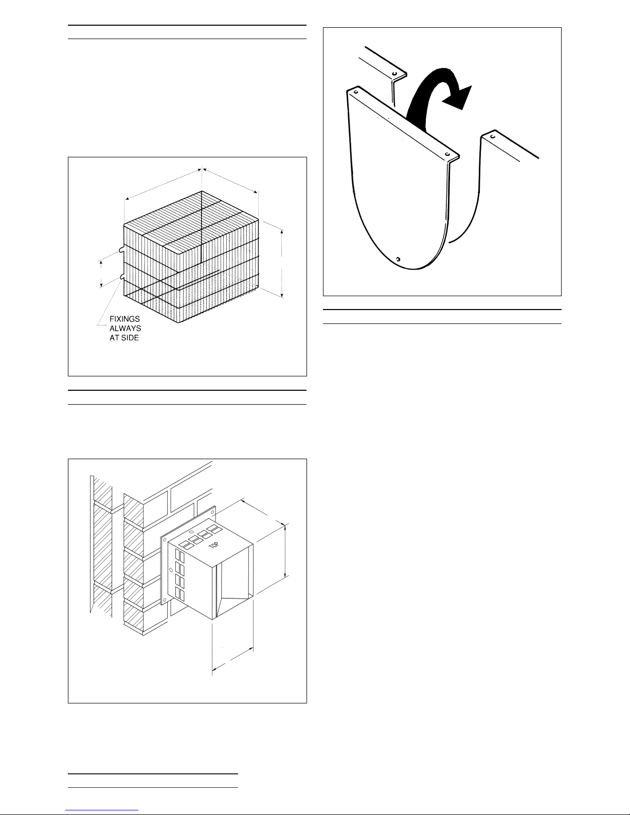
5:5 TERMINAL GUARDS
When the terminal is positioned where there is the
possibility of accidental contact by persons, or of
damage to the terminal, an approved guard is
necessary (Boulter Code FL26160).
Generally, exhaust 2 metres above ground level
alleviates the necessity for a guard.
A suitable guard is available from BOULTER
BOILERS as shown below.
5:6 HORIZONTAL FLUE TERMINAL
The Terminal for Horizontal Balanced Flue is
secured to the wall by means of four screws. The
indexing plate should have its four edges siliconed
to the outside wall to provide a weather seal.
5:7 BLANKING PLATES
The Boiler is supplied in Balanced Flue form. With
2 full side/rear Blanking plate and one top blanking
plate.
The Blanking plates should be fitted to prevent
access to hot surfaces and to maintain the
efficiency of the boiler.
Fig. 5.5a
Fig. 5.6a Wall plate FL47108
Fig. 5.7a Side Panel Blanking Plate
300
265
330
160
140
185
160
Page 23

BOULTER BOILERS Eco-System PAGE 21
6:1 NOTES ON INSTALLATION
LOW LEVEL AND HIGH LEVEL BALANCED
FLUES
1. The Terminal must be slightly angled down to
ensure correct operation of the boiler. Due to the
efficiency levels of Eco - System pluming from the
terminals may occur under certain conditions. Any
condensation may be acidic due to the fuel
characteristics and it is advisable not to install the
flue in any position where the condensation could
cause damage to paint surfaces etc.
2. The Terminal index plate should be sealed to
the external wall using silicon sealant or other
impervious material to prevent water ingress.
3. Ensure that the outlet of the Terminal points
downward (TOP upper-most and Boulter correct
way up).
4. Ensure that the boiler to offtake gasket is fitted
(foil face upwards) and the clamp is made with four
nuts and washers securely fixed.
5. Ensure that the ‘Sealing Rings’ are fitted in the
correct groove. Use a mild detergent as a lubricant
to ease assembly.
6. The Flue is telescopic and no cutting
of the flue
pipes is necessary.
7. 500mm and 1000mm flue extension kits are
available. Do not exceed the maximum flue lengths
stated in this manual.
8. The flexible air duct is an integral part of the
appliance and must be used on all balanced flue
kits. Ensure that it is not damaged and that either
end is connected via the jubilee clip provided to
ensure correct boiler operation.
Page 24
BOULTER BOILERS Eco-System PAGE 22
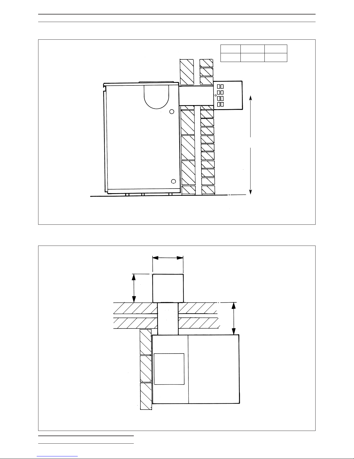
6:2 LOW LEVEL HORIZONTAL FLUE
6:2.1 Rear
6:2.2 Side - Right or Left Hand
Fig. 6:2a Low Level Horizontal Rear
Fig. 6:2b Low Level Horizontal Side
Model 12/19 19/26
Dim A 770mm 770mm
A
160
185
See attached colour
leaflet for dimensions
Page 25
BOULTER BOILERSEco-System PAGE 23
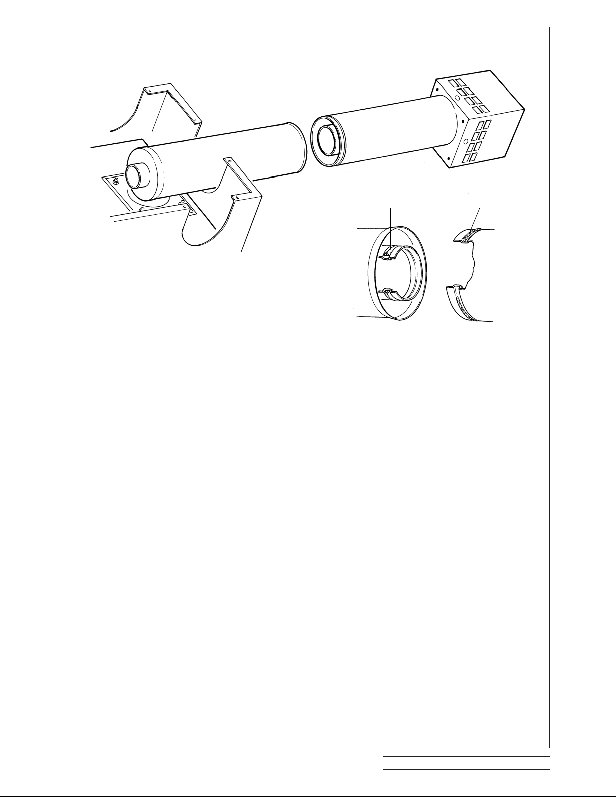
Fig. 6:2c Low Level Horizontal Flue Assembly
LOW LEVEL FLUE INSTALLATION
Site conditions will dictate to a certain extent the
best method of assembling low level balanced
flues.
The illustration shows a typical rear outlet flue.
Assemble the flue generally as follows:
1. Position boiler check that water connections
and flue proposed is according to clearances
specified.
2. Mark flue position.
3. Move boiler away from the wall and using a
diamond tipped core drill drill a 6” (150mm) hole,
ensuring the hole is horizontal.
4. Remove rear top panel of boiler and identify
flue outlet (rear, LH or RH side). Move blanking
plate to appropriate position using nuts and
washers.
5. Ensure flue exhaust seal is in position and in
good condition, ie undamaged. Lubricate with a
mild detergent.
6. Place boiler offtake gasket in position on top of
boiler (foil face upwards).
7. Lay internal flue in appropriate position in
boiler and offer up to hole in wall.
8. Secure internal flue to boiler via four nuts and
washers as supplied.
9. Remove outer terminal 4 screws and put
terminal to one side.
10. Taking outer air duct ensure Seal is fitted and
in good condition. Lubricate with a mild detergent.
11. Ensuring that there is no wall debris present in
either ducts slide outer air duct into inner air duct.
12. Using the four holes on the external wall plate
as a guide drill four fixing holes into the external
wall.
13. Replace the outer air duct and pushing firmly
home screw into position (4 screws).Weather seal
all edges.
14. Taking the terminal end keeping it square to
the external flange push home over the internal
flue exhaust pipe until the four holes on the flange
align. NB Ensure that TOP is on the upper most
surface of the terminal and ‘Boulter’ is upright.
15. Secure the terminal to the flange using the
four screws.
16.Fit an approved terminal guard if in an
accessible position. Available from Boulter
Boilers.
17. Inside:
Using the clips supplied fix the flexible air duct
to the burner spigot and flue offtake securely.
Continue on with the rest of the installation.
TOP
INNER SEAL
OUTER SEAL
Page 26
BOULTER BOILERS Eco-System PAGE 24
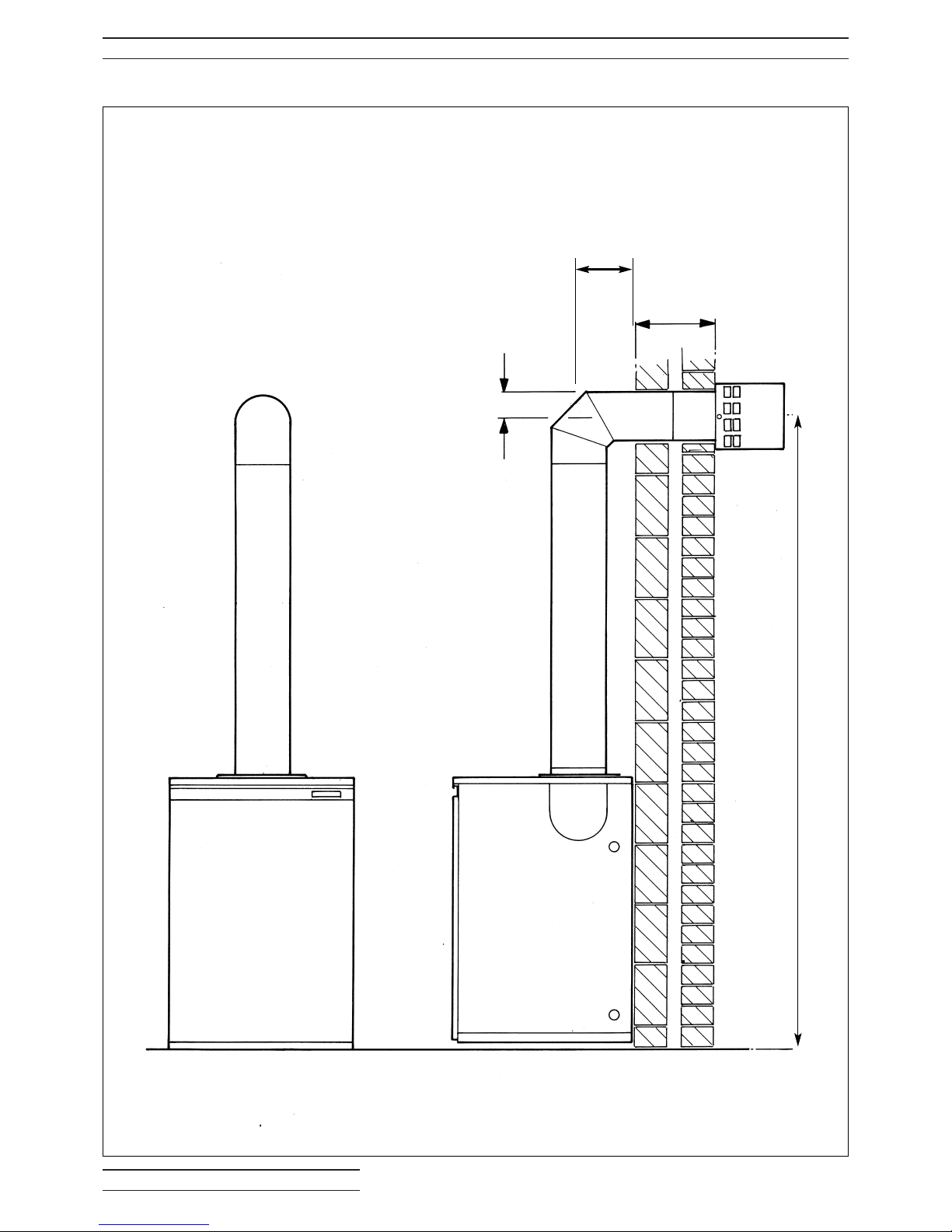
6:3 HIGH LEVEL HORIZONTAL FLUE
6:3.1 Rear
Fig. 6:3a High Level Horizontal Rear
66.5mm
A
See
attached
colour
leaflet for
details
DIM ‘A’ 135mm
See attached colour
leaflet for details
Page 27
BOULTER BOILERS Eco-System PAGE 25
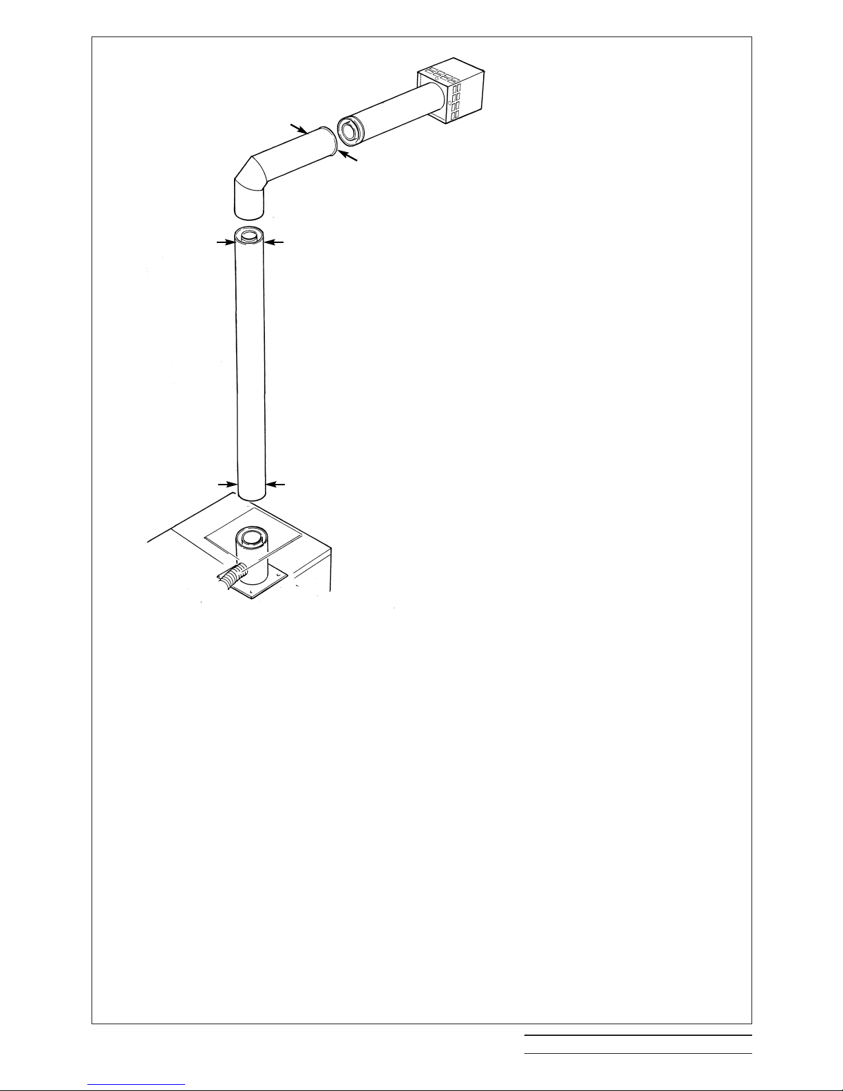
Fig. 6:3b High Level Horizontal Flue Assembly
HIGH LEVEL SIDE & REAR INSTALLATION
Assemble the flue generally as follows:
1. Position boiler check that all water connections and
proposed flue position are according to clearances specified.
2. Mark the flue position on the wall.
3. Move the boiler away from the wall and using a diamond
tipped core drill drill a 6” 150mm hole in the wall ensuring the
hole is level.
4. Remove the top panels of the boiler and fit the appropriate
blanking plate to rear panel using the nuts and washers
provided.
5. Fit the boiler offtake gasket to the four studs and fit offtake
spigot with the four nuts and washers provided.
6. Ensure the flue exhaust seal is in position and undamaged.
Lubricate with a mild detergent.
7. Fit the vertical flue offtake plate to the rear top panel of the
boiler and fit the assembly into position over the vertical offtake
spigot.
8. Take the 1000mm vertical extension and fit an O Ring seal
to the outer duct, lubricate with a mild detergent and ensure that
the flue exhaust seal is fitted to the inner duct undamaged and
in the correct orientation.
9. With the seals fitted slide the extension into the offtake
socket external O Ring end first.
10. Take High Level elbow fit larger O Ring seal to short arm,
lubricate with a mild detergent and ensure flue exhaust seal is
fitted to the inner duct undamaged and in the correct orientation.
11. Ensuring there is no debris in the wall place longer arm
through drilled hole and slide into second extension being careful
not to scratch metal work.
The high level elbow must be slightly sloped downwards.
12. Using the drill provided drill 6 holes as indicated on the
drawing and secure with the self tapping screws supplied.
13. FROM OUTSIDE
Remove the outer terminal four screws and put terminal to
one side.
14. Taking outer air duct ensure Seal is fitted and in good
condition.
15. Check wall cavity for debris and remove if necessary. Slide
the outer air duct into the inner air duct until home.
16. Using the four holes on the external wall plate as a guide
drill four fixing holes into the external wall to suit those supplied.
17. Replace the outer air duct and pushing firmly home screw
into position (4 screws). Weather seal all edges.
18. Taking the terminal end, keeping it square to the external
flange push home over the internal flue exhaust pipe until the
four holes on the flange align.
NB. Ensure that TOP is on the upper-most surface of the
terminal and BOULTER is upright.
19. Secure the terminal to the flange using the four screws.
20. Fit an approved terminal guard if in accessible position.
Available from Boulter Boilers.
21. INSIDE
Use the clips supplied to fix the air duct to the burner spigot
and vertical flue offtake spigot
Continue with the rest of the installation.
drill
drill
drill
drill
drill
drill
Page 28
BOULTER BOILERS Eco-System PAGE 26
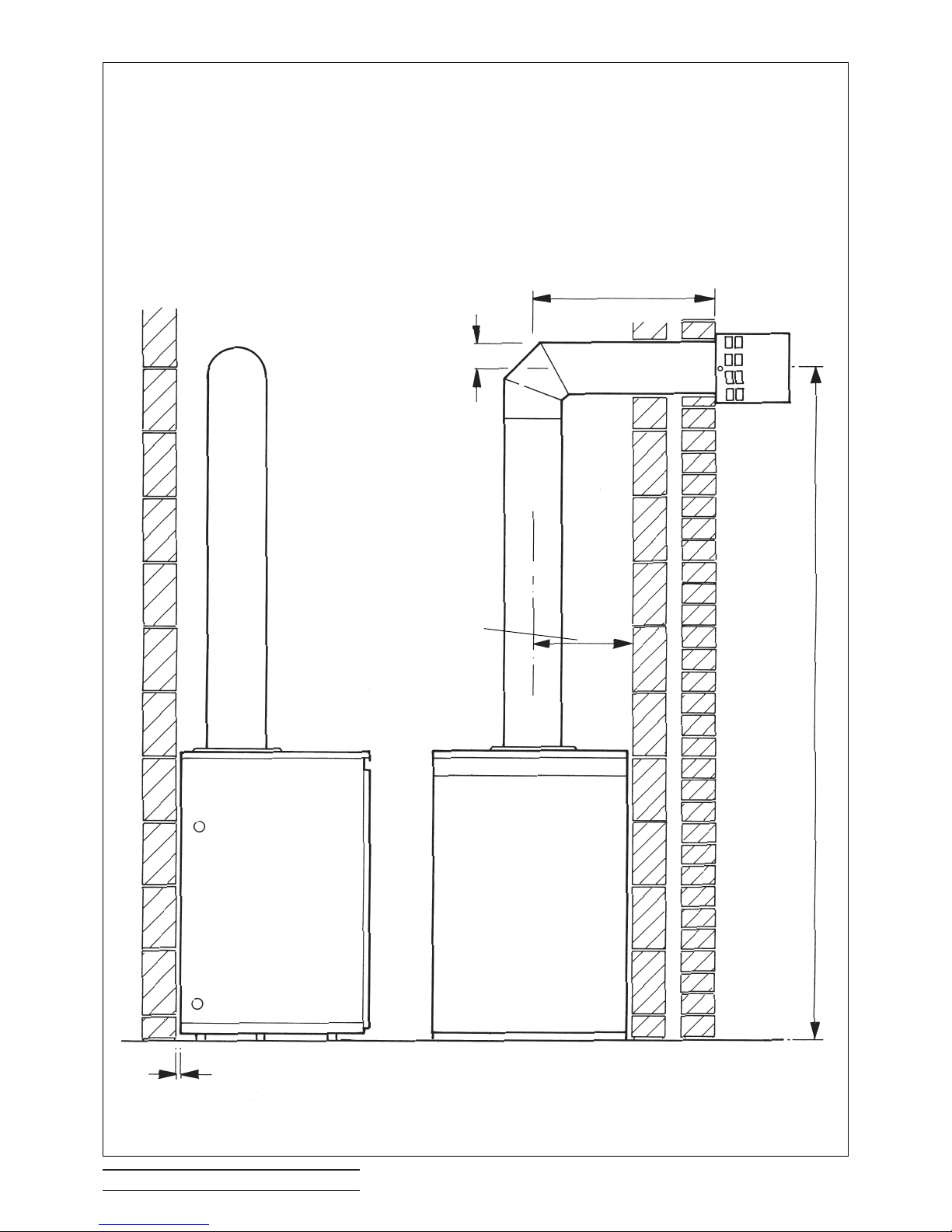
Fig. 6:3d High Level Horizontal Flue Side
6:3.2 Side - Right or Left Hand
See attached colour
leaflet for details
See attached colour
leaflet for details
323mm
66.5mm
5
Page 29

BOULTER BOILERS Eco-System PAGE 27
6:4 VERTICAL FLUE INSTALLATIONS
6:4.1 Notes on installation
Site conditions will dictate the best method of
assembling the vertical balanced flue.
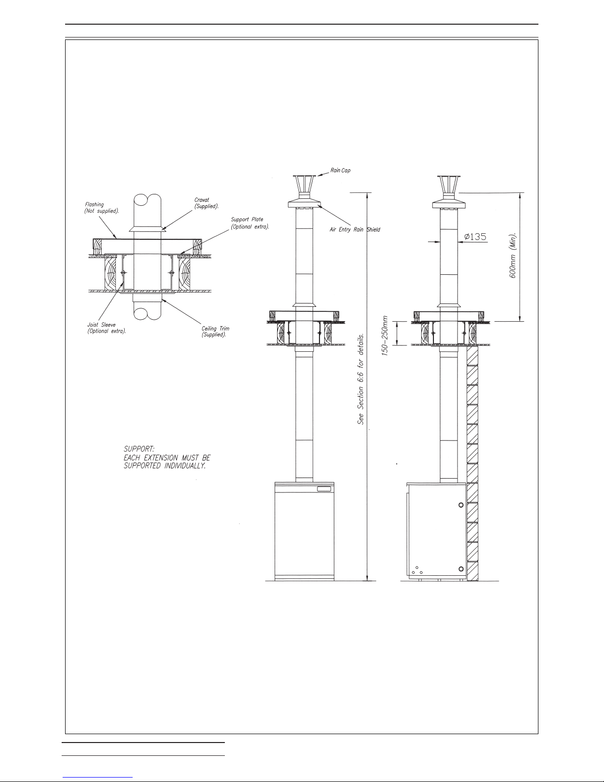
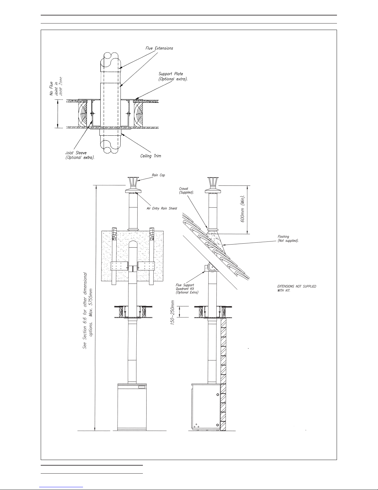
Illustrations fig 6:4a & b show typical flat roof
installations and illustrations fig 6:4c & d show
typical pitched roof installations.
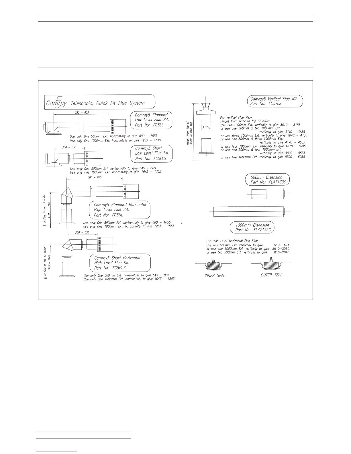
Refer to 6:6 for details of extensions required. The
flue system is telescopic and the extensions fit
between the vertical offtake spigot and the flue
terminal.
Ensure at least 50mm overlap.
Remove the rear top casing panel and fit the
vertical offtake spigot to the boiler using the four
nuts and washers - sandwiching the gasket
supplied between the boiler and spigot.
Where a flue system passes through a joist frame
it is essential that the integrity of the ceiling fire
barrier is retained. The optional extras - joist
sleeve and support plate are recommended.
Alternatively this can be achieved by following the
Building Regulations.
Joints in the flue must not be situated within the
joist space.
Joints must be a minimum of 150mm below
ceiling height.
Flue parts are assembled by sliding them
together. The seals must be lubricated with the
mild detergent supplied to assist fitting and sliding
of parts. When flue parts have been set the
desired length they should be drilled and self
tapping screws used to fix them.
When preparing the ceiling/roof for the flue above
the boiler it is advised to place the boiler in
position, check locations of flow and return
connections, oil supplies and general clearances.
When satisfied mark the ceiling for cutting
appropriate hole/s. Cover or move the boiler
during the ceiling/roof preparation. Holes should
be cut close to the size of the flue, say 10mm
clearance.
A ceiling trim is provided which is slid onto the
extensions during assembly and installation and
is screwed to the ceiling. When the installation of
flue extensions is complete finish off flashing, fit
the cravat and seal between the cravat and flue
with a suitable weather proof sealant. Slide on the
terminal and secure with screws.
Using the clips provided connect the flexible air
duct to the burner spigot and the other end to the
flue offtake spigot.
Page 30
BOULTER BOILERS Eco-System PAGE 28
6:4 VERTICAL FLUE FLAT ROOF INSTALLATION
Fig. 6:4a Vertical Flue - Flat Roof
Page 31
BOULTER BOILERS Eco-System PAGE 29
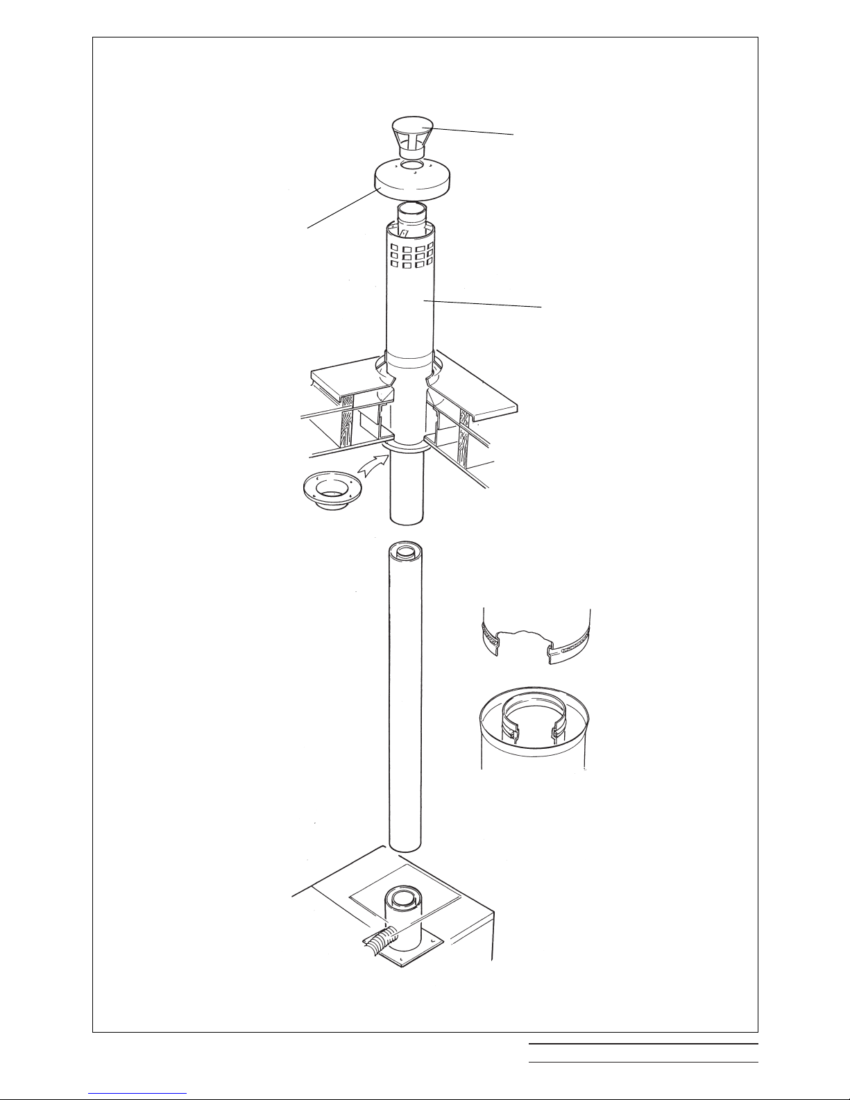
Fig. 6:4b Vertical Flue - Flat Roof Assembly
Rain Cap
Air Entry Shield
Vertical Terminal Body
Ceiling Trim
Page 32
BOULTER BOILERS Eco-System PAGE 30
6:4 VERTICAL FLUE PITCHED ROOF INSTALLATION
Fig. 6:4c Vertical Flue - Pitched Roof
Page 33
BOULTER BOILERS Eco-System PAGE 31
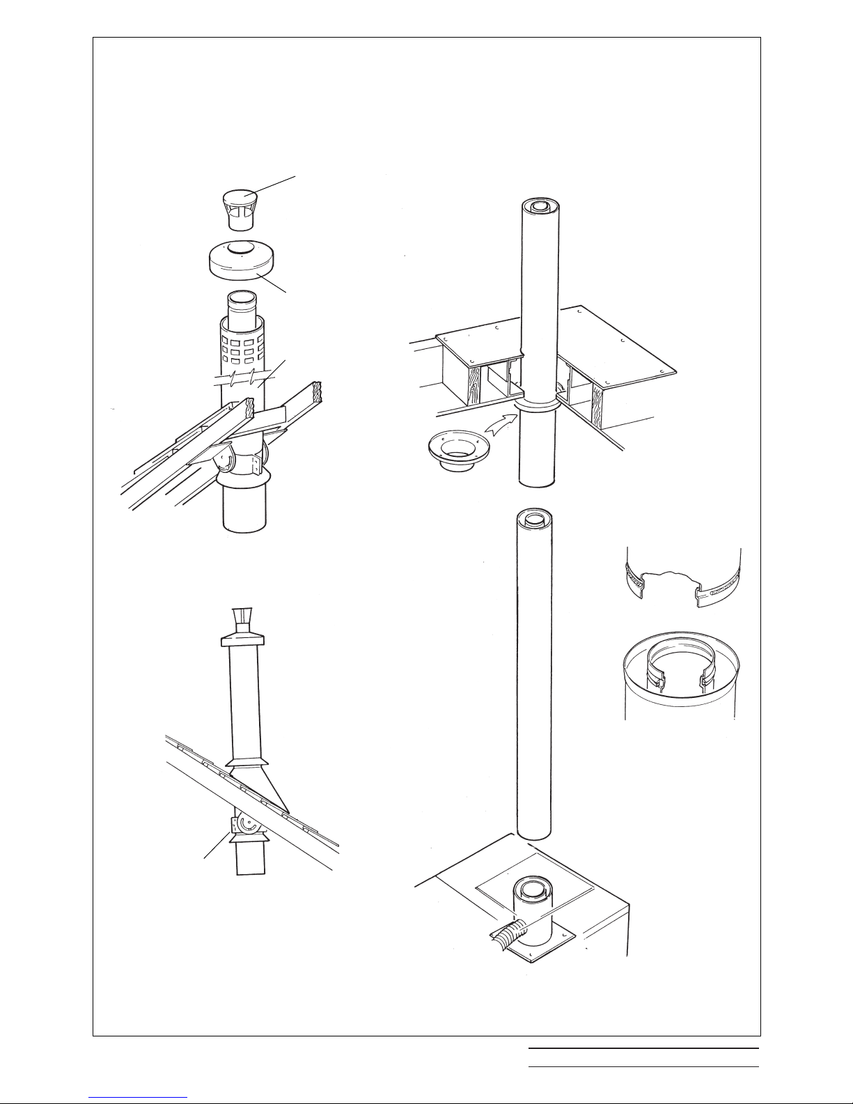
Fig. 6:4dVertical Flue - Pitched Roof Assembly
Rain Cap
Air Entry Rain Shield
Vertical Terminal Body
Flue Support
Quadrant Kit
Page 34
BOULTER BOILERS Eco-System PAGE 32
6:5 HIGH LEVEL FLUE LENGTH ALTERATION
There is a certain amount of adjustment available on the vertical height and horizontal length.
This is attained by pushing two telescopic flues together until the desired dimension is obtained. Secure
any vertical lengths by using a drill and 4 self tapping screws supplied.
6:6 QUICK FIT FLUE SYSTEMS
Page 35

BOULTER BOILERS Eco-System PAGE 33
7:1 COMMISSIONING
It is essential in the interest of boiler efficiency and
reliable performance that once the boiler has been
installed it is first commissioned by a competent
engineer, preferably an OFTEC commissioning
engineer.
If an engineer is not known Boulter Boilers will be
pleased to provide details of commissioning and
servicing engineers from their register.
Commissioning must be carried out at the point of
first firing.
Incorrect emissions can cause premature fouling of
the flue ways.
7:2 RESPONSIBILITY
It is the responsibility of the installer to ensure that
the boiler is properly commissioned. It is essential
that the commissioning procedures detailed in this
manual are carried out by a qualified engineer
using recognised test equipment.
It is recommended that the relevant section of BS
5410: Part 1: latest edition is carefully read.
7:3 REPORTING
It is recommended that you use a report sheet and
check list. Make comments on the report where
necessary, and give a copy to whoever has
engaged your services, and retain and file your
own copy. A suggested layout is shown over.
It is the responsibility of the installer
to ensure that the boiler is
commissioned by a competent engineer,
preferably an OFTEC* Registered
Commissioning Engineer.
IMPORTANT
Page 36

Tick off each item
OIL TANK
❐ Is there sufficient oil, and of the correct grade
for the appliance?
❐ Is the tank adequately supported?
❐ Is a damp-proof membrane inserted between
the tank and support? (Non plastic tanks).
❐ Does the tank slope at least 20mm per metre
of length downwards towards the sludge cock?
(Non plastic tanks).
❐ Is the tank painted or suitably protected
externally?
Is the tank fitted with the following:
❐ Contents gauges
❐ Screw fill and indepentant vent cover or
capped fill and vent pipes.
❐ Outer valve
❐ Filter
❐ Sludge cock (Non plastic tanks).
HEIGHT OF TANK
❐ Is the bottom of the tank above the oil pump if
a single pipe system is installed?
OIL SUPPLY LINE
❐ Ensure that galvanised iron has not been used.
❐ If black iron has been used, is it protected
against corrosion?
❐ Ensure that soldered connections on copper
pipes have not been used.
❐ Is the size of the pipe adequate for the boiler
rating?
❐ Are all joints leak proof?
❐ Is a fire valve fitted?
❐ Is a filter fitted? (correct way round)
❐ Is the oil line connected to the correct inlet
connection of the pump?
❐ Is the oil supply clean and free of water or
other contamination?
❐ Disconnect the oil supply as close to the
burner as possible and drain approximately a
gallon of oil into a very clear container. Inspect the
oil for impurities and repeat the process if
necessary.
Do not re-connect the oil line until water and all
impurities have been removed from the oil
supply.
IF NOT THIS MAY DAMAGE THE PUMP.
❐ Clear oil filters and de-sludge the tank if
necessary.
TWO PIPE OIL SYSTEMS
❐ Is a spring-loaded non-return oil valve fitted in
the suction line? (or a 3K Oil Deaerator).
❐ Does the return oil line terminate in the take at
the same level as the suction outlet?
❐ Has an anti-syphon cut been made in the
return oil line (inside the tank)?
BOILER
❐ Is the boiler standing on a level incombustible
hearth?
❐ Are the thermostat phials inserted in their
pockets?
❐ Are the baffles and bottom insulation (where
applicable) correctly located?
❐ Is the boiler set for the fuel being supplied?
❐ Has the system and boiler been filled with
water and inhibitor as required?
❐ Is the boiler flueway inspection cover screwed
down sufficiently firmly to form a seal?
BOULTER BOILERS Eco-System PAGE 34
7:4 BOULTER BOILERS RECOMMENDED COMMISSIONING CHECK LIST - SHEET 1 OF 2
Customer...............................................
Site Address ..........................................
...............................................................
Appliance Model....................................
Serial No................................................
Fuel........................................................
Page 37

BOULTER BOILERS Eco-System PAGE 35
CASING PANELS
❐ Have grommets been fitted to relevant oil
supply entry points (knockouts)?
❐ Does electrical cabling pass through a
grommet to prevent chaffing?
BURNER
❐ Is the oil pump by-pass screw fitted, if
applicable?
❐ Remove the burner. Is the correct nozzle
fitted?
NOTE:- Burner operating instructions can conflict
because they are intended for general guidance.
Since the burner has been specifically matched to
the particular boiler, the information in the Boiler
manual takes precedence.
FLUE AND CHIMNEY
❐ Is the flue adequately sized for the appliance
rating?
❐ Is the flue free of any obstruction?
❐ Has the chimney been adequately lined and
insulated?
NOTE:- Lining the flue and back filling will help
prevent condensate problems
BALANCED FLUE APPLIANCES
❐ Is the correct flue kit fitted?
❐ Is the Flue off take correctly secured to the
boiler by four nuts and washers. Is the gasket
provided fitted correctly?
❐ Has the rear Air Entry Plate been fitted with
Blanking Plates where necessary?
❐ Can leakage from flues tubes or air ducts
occur? All seals fitted correctly?
❐ Is the sampling test point (on high level or
vertical kits) resealed?
VENTILATION
CONVENTIONAL FLUED BOILERS
❐ Is the ventilation opening from the outside to
the boiler room adequate?
❐ Is there sufficient clearance for air to enter the
Boiler at the rear of appliance?
❐ Will any ventilation fans prevent adequate
supply of combustion air?
❐ Is the CF adaptor fitted correctly to the boiler
with all nuts and gaskets?
❐ Is the sampling test point resealed?
ELECTRICAL POWER SUPPLY
❐ Is the electrical supply to the appliance
appropriate?
❐ Are the electrical input connections to the
control panel correct?
❐ Is the supply fuse correct?
❐ Does the wiring comply with the latest IEE
regulations?
❐ Does the power supply cable enter the casing
through a grommet?
GENERAL
❐ Has the boiler been installed in accorandance
with manufacturers instructions?
7:4 BOULTER BOILERS RECOMMENDED COMMISSIONING CHECK LIST - SHEET 2 OF 2
Page 38

BOULTER BOILERS Eco-System PAGE 36
7:5 BOULTER BOILERS RECOMMENDED COMMISSIONING TESTS
❐ Have the manufacturers on-site assembly
instructions been followed?
COMMISSIONING TESTS
❐ BEFORE ATTEMPTING TO START THE
BOILER PLEASE THOROUGHLY CHECK ALL
ITEMS ON THE COMMISSIONING CHECK LIST.
THIS WILL HELP TO AVOID UNNECESSARY
CALL BACKS
❐ ENSURE THAT THE BOILER IS MATCHED
MOST CLOSELY TO THE HEATING SYSTEM
REQUIREMENTS BY FITTING THE CORRECTLY
SIZED NOZZLE AND/OR CHOOSING THE
CORRECT OIL PRESSURE.
❐ Fit combined air bleed manifold and 0-300psi
(0-20 bar) pressure gauge to the appropriate oil
pump connection, and replace burner.
❐ Set the boiler thermostat to between Summer
and Winter positions, see fig. 1.
❐ Switch on the electrical supply to the boiler,
checking that programmers are switched to the
‘ON’ position, and that the room thermostats are
calling for heat.
When the burner motor starts, on one pipe
systems it may be necessary to temporarily open
the air bleed screw on the test manifold.
If the burner locks out during the ignition attempt,
wait 45 seconds before pressing the reset button
on the control box. Several attempts on first firing
may be necessary.
❐ Once the burner is firing check and if
necessary adjust the oil pressure.
❐ CARRY OUT COMBUSTION CHECKS BY
INSERTING PROBES INTO SAMPLING POINTS
PROVIDED:
Low level balanced flue, rear or side - end of
terminal.
High level balanced flue, rear or side - end of
terminal, or TEST POINT in boiler.
Vertical balanced flue - TEST POINT in boiler.
Conventional flue - hole provided via screw in
vertical offtake section.
❐ Check the Smoke No., if clean wait 10 minutes
and measure CO
2.
❐ Adjust the air shutter if necessary, open to
reduce CO
2, close to increase CO2.
If the air shutter is adjusted, re-check the Smoke
No.
❐ Check the flue gas temperature.
The figures should agree with the Boiler
Commissioning Data.
❐ Check lockout function, either cover the
photocell or remove solenoid coil, to simulate flame
failure. Reinstate components and press lockout
button.
❐ Check the operation of the limit thermostat
❐ Complete commissioning report and enter the
details on to the guarantee form which should be
returned to BOULTER BOILERS in the envelope
provided.
❐ Instruct the user on the operation of the
appliance and leave this manual with the customer.
Page 39

BOULTER BOILERSEco-System PAGE 37
8:1 MAINTENANCE
A boiler fired with Class C Oil should only require
attentions once each year.
8:1.1 General Inspection
With the Boiler operating, inspect for signs of
unsatisfactory operation, i.e. leakage of
combustion products, leakage of oil, or unusual
noises from the pump or motor.
Check the commissioning list if it is your
attendance to the appliance. Is there a reason why
the Boiler might fail after you leave?
It is useful to measure the combustion date, i.e.
CO2, Smoke No. and flue gas temperature, and a
check on the oil pressure, prior to carrying out
maintenance work.
8:1.2 Maintenance Procedure
Switch off electrical supply at the MAINS
ISOLATING SWITCH.
OIL TANK
De-sludge oil tank (if necessary), and draw of any
accumulated water.
Check the correct grade of oil is being used.
FILTERS
Inspect and clean all oil filters. Change paper
elements for new.
BURNER
Turn off the oil cock and disconnect the flexible oil
hose from the oil cock.
Remove burner and clean thoroughly, the burner
draught tube, the electrodes and generally the
head assembly. CHANGE the nozzle for one with
the specified make, oil rate, spray pattern and
angle.
Inspect the ignition electrodes for crazing in the
porcelain. Replace if there are signs of
deterioration.
A dirty fan impeller can impair the performance of
a burner, inspect and clean if necessary.
Inspect photocell, if badly discoloured, change it.
Inspect the flexible oil hose for leaks or
discolouration. Use only replacement flexible oil
hoses that are detailed in the spare parts section of
this manual.
BOILER
The Boilers are serviced from the front.
Remove flue inspection cover/s, and baffles, and
clean all heat transfer surfaces and baffles.
Replace any damaged or unserviceable parts with
manufacturers proprietary parts.
Inspect flue and air ducts for deterioration of seals,
and repair if necessary. Re-lubricate with a mild
detergent when refitting.
Refit parts and inspect seals etc. which should be
replaced if required.
COMBUSTION TESTS
Fit combined air bleed manifold and 0-300psi (0-20
bar) pressure gauge to the appropriate oil pump
connection, and replace burner.
Switch on the electric supply to the boiler.
When the burner motor starts, on one pipe
systems, it may be necessary to temporarily open
the air bleed screw on the test manifold.
Once the burner is firing check and if necessary
adjust the oil pressure.
Carry out combustion checks by inserting probes
into sampling points provided or at the flue outlet.
Check the Smoke No., if clean wait 10 minutes and
measure CO
2.
Adjust the air shutter (see fig 8.2a), if necessary,
open to reduce CO
2, close to increase CO2.
If the air shutter is adjusted, re-check the Smoke
No.
Check the flue gas temperature.
The figures should agree with data in Boiler
Commissioning Data, Section 3.
FINAL CHECKS
Check lockout function, either remove photocell
and cover it, or remove solenoid coil, to simulate
flame failure. Reinstate components and press
lockout reset button.
Check that the control thermostat is operating
when the set temperature is reached.
Check the operation of the limit thermostat if
possible.
Reset Limit thermostat once appliance
temperature has dropped sufficiently.
Complete a maintenance report and give the
customer a copy, retaining a copy for your records.
Page 40
BOULTER BOILERS Eco-System PAGE 38
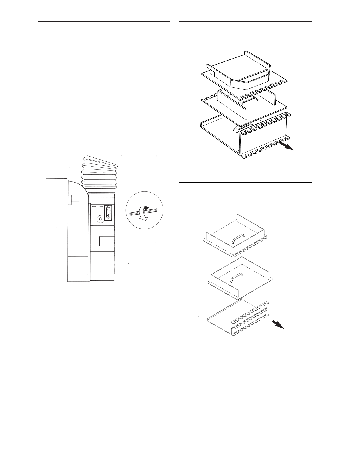
8:2 AIR SHUTTER ADJUSTMENT
The Burner has a fixed Air Shutter with manual
adjustment.
To adjust the CO
2 at the Air Shutter use a 3mm
allen key as shown.To increase the setting turn the
airshutter clockwise (+) and to decrease turn anticlockwise (-).
8:3 BAFFLE ARRANGEMENT
To ensure correct placement of baffles ensure
that castellated edges are positioned towards the
heat exchanger and:
1. All baffles are horizontal
2. All baffle handles are in the forward position.
12/19
TOP
FRONT
TOP
FRONT
Fig. 8:2a Air Shutter Adjustment
Fig. 8.3a Baffle Arrangement
19/26
Page 41
BOULTER BOILERS Eco-System PAGE 39
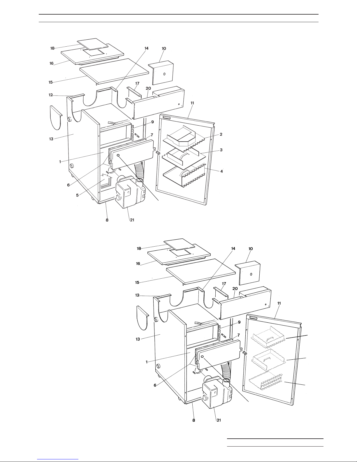
9:2 BOILER SPARE PARTS 12/19 & 19/26 BOILERS
Fig. 12/19
Fig. 19/26
SAMPLE
POINT
SAMPLE
POINT
2
3
4
Page 42

9:2 BOILER SPARE PARTS 12/19 & 19/26 BOILERS
BOULTER BOILERS Eco-System PAGE 40
1
2
3
4
5
6
7
8
9
10
11
12
13
14
15
16
17
18
19
20
22
23
24
25
26
27
Heat Exchanger (Short Boiler only)
1st Baffle Top
2nd Baffle
3rd Baffle
Combustion Chamber Base Insulation
Inspection Cover complete
Inspection Cover Insulation (Ceraboard)
Base Tray
Heat Exchanger Insulation Set
Heat Shield
Door Panel
Rear Casing Panel
Left Side Casing Panel
Right Side Casing Panel
Top Front Panel
Top Rear Panel
Side Panel Blanking Plate
Blanking Plate
Control Panel Complete
Riello Burner Complete Type
Part No.
Burner Airduct
Side Panel Bracer
Side Flue Plate
SB40/65
HE47021C
HE47022C
HE47023C
IN47103
HE47218C
IN47201
PN47201C
IN49200C
PN23116
PN47235C
PN49202
PN47223C
PN47224C
PN31206C
PN49207C
PN49117
PN49108
PN57050C
484T50
3748455
RP47001
PN47214C
PN47118C
Item Description
Eco
21
SB65/95
HE47022C
HE47022C
HE47073C
N/A
HE47218C
IN47201
PN47201C
IN49200C
PN23116
PN47235C
PN49202
PN47223C
PN47224C
PN31206C
PN49207C
PN49117
PN49108
PN57050C
483T50
3748355
RP47001
PN47214C
PN47118C
12/19 19/26
Note: Items 22-26 not shown.
Page 43
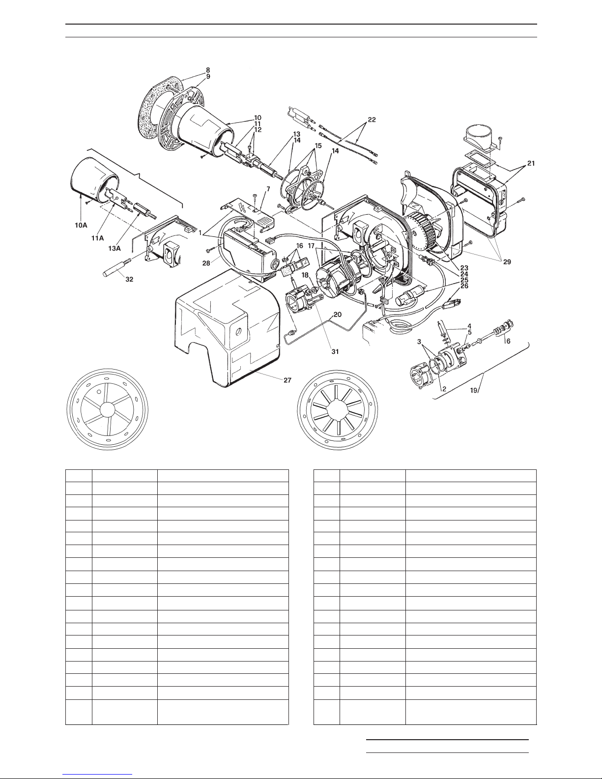
9:4 BURNER PARTS - TYPE 483T50 & 484T50
BOULTER BOILERS Eco-System PAGE 41
Item
1
2
3
4
5
6
7
8
9
10
10A
11
11A
12
13
13A
14
15
15A
Part No.
3008652
3007162
3008653
3007582
3008651
3000439
3008649
3005787
3006384
3008768
3008859
3007513
3008860
3006552
3008642
3008861
3007178
3008543
3008862
Description
Control Box 535RSE/LD
O Ring
Filter O Ring
Needle Valve
Regulator
Pump Seal
Protection Cover
Gasket
Flange
Blast Tube
Blast Tube (484T50)
Electrode Assembly
Electrode Assembly (484T50)
Electrode Bracket
Nozzle Holder
Nozzle Holder (484T50)
O Ring
Collar (Includes O Rings)
Collar (484T50)
Item
16
17
18
19
20
21
22
23
24
25
26
27
28
29
29
29
31
32
33
Part No.
3008648
3008650
3000443
3008654
3008644
3008647
3008794
3005708
3008646
3007479
3008863
3008879
3008877
3008878
3008878
3008878
3008876
3008875
Description
Coil
Motor
Joint
Pump
Tube
Air Damper Assembly
High Voltage Lead
Fan
Photo Electric Cell
Capacitor 4µF
Burner Lead
Burner Cover
Solenoid Lead
Air Box Seal
Fan Box Seal KIT
O Ring Seal
Pressure Gauge Extension
Electrode Clamp (484T50)
12 / 19 Blast Tube
end view
19 / 26 Blast Tube
end view
Page 44

BOULTER BOILERS Eco-System PAGE 42
10:1 FAULT FINDING
If the Boiler fails to start, make the following checks before calling a service engineer:-
1. Is there sufficient fuel in the storage tank?
2. Are all fuel supply valves open (turned fully anti-clockwise) and ball valves open?
3. Is the mains electricity supply switched on?
4. Is the programmer (or Boiler Operating Switch) set to call for heat?
5. Is the Boiler Thermostat set to the desired temperature?
6. Is the Lock-out Reset Button on the Control Box and Control Panel Neon illuminated? If so, press to
reset Burner.
7. Check the fuse which should have been fitted to the mains electricity supply to the programmer/boiler
operating switch. If the fuse has blown, replace it. If it blows again, call a Service Engineer.
IMPORTANT - Electrical Safety
IT IS ESSENTIAL THAT BEFORE ANY PANELS OR COMPONENTS ARE REMOVED FROM THE
BOILER, THAT THE MAINS ISOLATOR IS SWITCHED OFF.
10:2 Fault Finding Chart
Trouble or Complaint Possible Cause Action
1. Suspect oil supply No oil in tank Check and arrange for tank to be filled if necessary
Supply valves closed Open all supply valves
Blockage in oil supply Shut off the burner isolating valve. Disconnect
(Gravity head feed) the oil supply at the pump entry. Place receptacle
under the pipe. Slowly open the valve, not is the
flow is unrestricted, restricted or blocked.
Wrong grade of oil Check for correct grade of fuel (see technical data)
Water contamination Open tank, drain valve and check
Tank vent blocked Check
Filter blocked Check for water or blockage
Air locks in supply pipe Check for high points in main oil supply
Air lock in pump Bleed pump, check flexible oil line.
2. Burner will not start Interruption or absence Check mains switch on. Check fuse in switched
of electrical supply at spur or plug. Check that time switch or programmer
burner (Check this at contacts are closed. Check that the auxiliary stat
Control Box mains is closed. Check boiler stat, cylinder stat, room
terminal with test lamp) stat are calling for heat.
Control Box is locked out, Press reset button on the burner box
refer to symptom 4
Photo-resistor receiving Check that the photo-resistor is fully home in its
false light housing. Burner will not start with illuminated cell.
Faulty control box Replace.
3. Burner lights up but locks No oil supply Check oil in the tank.
out after 15 seconds
Photo-electric cell not Check that photo-electric cell is clean and fully
receiving light from flame home in housing
Photo-electric cell Check and tighten if necessary.
connections loose
Control box photo- Replace control box.
electric cell circuit
faulty
Flame instability Check combustion setting out and reset if
necessary.
Page 45

BOULTER BOILERS Eco-System PAGE 43
4. Burner starts but will not This can be due either
light up to absence of oil of
ignition.
Oil pump air locked Pump should be self-venting with two pipe system
(repeat air locking only. If a one pipe gravity feed is employed it must
may be due to poor be purged through the vent port.
pipe joints or
defective gland
packings)
Motor not driving Check that flexible drive is functioning correctly
pump shaft and not slipping.
Blocked atomiser Remove and replace nozzle.
nozzle
Oil pressure Check oil pressure on gauge and set to the correct
abnormally low pressure (see technical data).
Solenoid valve faulty Break union at outlet to check presence of oil.
Check that seat is clear. Check coil for continuity.
Inspect coil feed wiring to control box.
Pump rotation Check.
incorrect
Ignition failure:
Electrodes dirty Inspect and clean if necessary.
Electrodes mis-set Inspect and reset gap 3 to 4mm between tips.
2mm in front of nozzle face.
Cracked electrode Check and replace if cracked or crazed.
insulator.
Electrode leads Check for proper connections
5. Burner lights up, runs Air shutter closed Reset to correct position.
continuously and emits
visible smoke or shows Wrong nozzle Check make, type and spray angle.
excess smoke on
combustion check Worn atomiser nozzle Replace if necessary.
Oversize nozzle fitted Check size and replace with correct size of
in error necessary.
Nozzle incorrectly Replace with correct nozzle.
stamped
Burner air supply Inspect air intake and fan for fouling of impeller
inadequate with dirt.
Burner oil pressure Check pressure and reset to correct pressure (see
excessive Technical Data).
6. Burner lights up, runs Air in nozzle Should self-correct; if air repeatedly present;
normally but flame cuts for leaks on oil line and flexible.
off slowly on shut down
(possibly with smoke or Magnetic valve not Inspecting and replace if necessary.
pulsation) operating correctly
Shut off piston in Replace pump.
pump sticking
7. Burner Pulsates Air shutter setting Inspect and reset or remove blockage.
(a) continuously incorrect or fan inlet
blocked
Grossly oversized Checked and replace with correct size and type
nozzle (see Technical Data)
Air supply inadequate Check fan operation and cleanliness.
Page 46

BOULTER BOILERS Eco-System PAGE 44
7. Burner pulsates Worn nozzle with Replace with nozzle of correct type and size (see
(a) continuously excess throughout or Technical Data).
uneven spray pattern
(b) at initial firing Air in supply line Purge at pump to remove.
Blocked flue ways Clean boiler and flue.
8. Burner locks out on Localised low voltage Check with local Electricity Board to fit recorder.
morning starts then runs supply in early Enlist aid of the Board.
perfectly for rest of day morning
Air present in oil Restart burner several times - press lockout reset
supply button repeat 7(b) above.
Bottom of oil tank Raise tank or install a two pipe oil supply from
below level of oil tank.
pump
Non-return valve Renew non-return valve. Rectify air leak
faulty or air leak in
two pipe oil supply
system.
9. Burner fails due to blown Short circuit in wiring Inspect wiring, sheathing and inter-component
fuse. connections for broken or damaged leads.
Replace if necessary.
Motor seized Check by hand and replace if necessary.
Breakdown of Replace motor.
insulation of motor
windings
10. Burner runs normally but Oil throughput Check nozzle size and pressure against rating
will not reach desired insufficient
temperature
Boiler has become Check with heating installer.
undersized due to
heating system
expansion
Low efficiency and Check combustion readings, reset air.
CO
2
Low efficiency due to Clean heat exchanger surfaces
high flue gas
temperature
Faulty boilerstat. Replace, check and clean.
Partially blocked filter
11. Poor combustion Low CO
2
Check: CO2, oil pressure, nozzle size (see
readings Technical Data
High CO
2
Check: CO2, oil pressure, nozzle size (see
Technical Data
High smoke Check: CO2, oil pressure, nozzle size (see
Technical Data
Check all Baffles are in place and correctly located.
High flue gas Check: air shutter, nozzle size (see Technical
temperature Data), clean heat exchanger surfaces.
12. Oil odour Leaking joints Break all leaking joints and re-make
Page 47

BOULTER BOILERS Eco-System PAGE 45
13. High operating Control stat failed and Replace control stat and reset Limit Thermostat
temperature operating on limit stat
14. Fumes in Boiler Room Inadequate draught Take necessary corrective action
due to unsatisfactory
chimney or blockage
of boiler flue ways or
flue pipe
15. Unstable flame, some Air damper on burner Set up burner as for commissioning using oil
puffing, ignition cuts in improperly adjusted pressure gauge, smoke pump, CO2 indicator and
intermittently or faulty nozzle or draught gauge, adjust settings as necessary,
unsatisfactory draught replace nozzle if necessary.
conditions or fault in See Commissioning Check List and Servicing
oil supply Notes.
Page 48

1:1 Introduction
1:2 Regulations
1:3 Boiler Arrangement
1:4 Sealed System Components
2:1 Wiring Diagrams
2:2 Service Connection Dimensions
2:3 Tundish Position
2:4 Pipe Connection Details
2:5 Control Panel
2:6 Filling the System
2:7 Pressure Relief Valve
2:8 Expansion Vessel Pressure
3:1 Access
3:2 Water System
3:3 Additional Servicing
4:1 Sealed System 12/19 & 19/26
SECTION 1 - INTRODUCTION
SECTION 2 - INSTALLATION
SECTION 3 - SERVICING
SECTION 4 - SPARE PARTS
SECTION 5 - PUMP PERFORMANCE
BOULTER BOILERS Eco-System PAGE 46
CONTENTS - Part 2
Page 49
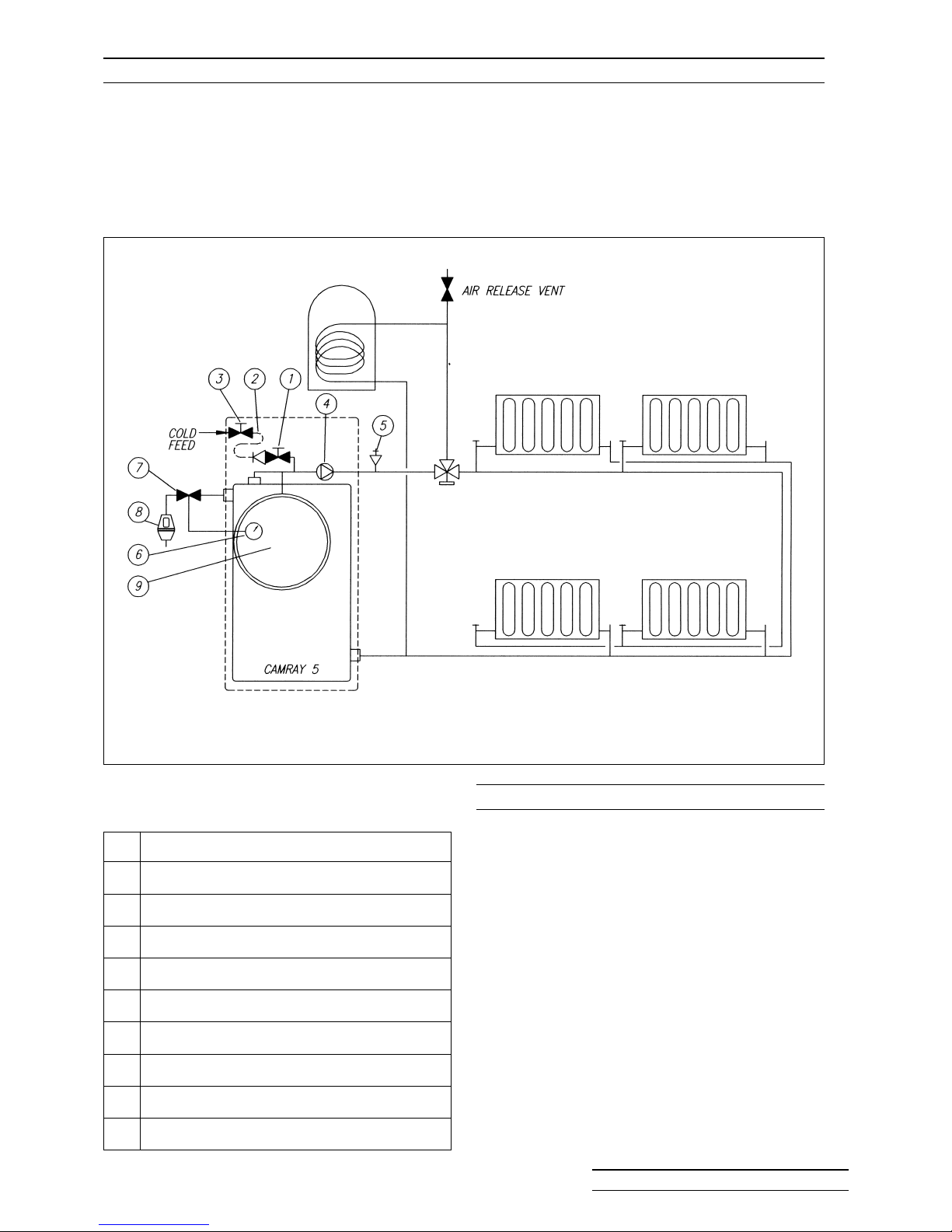
1:1 INTRODUCTION
1:2 REGULATIONS
Boulter Eco Sealed System Boilers are designed for use in sealed water systems. The
Boilers are supplied with an expansion vessel and associated components arranged to minimise
installation time.
Sealed System Boilers can be used for Conventional Flue or with any of the Boulter Balanced Flue
options available for the Camray 5, except side low level.
Fig. 1:1 Typical Sealed System Arrangement
Components Supplied with Boiler - Fig 1:1
The installation must comply with the requirements
of the latest editions of:
BS5449 Part 1 Forced Circulation Hot Water
System;
BS7074 Part 1 Codes of Practice for Sealed
Systems;
The Building Regulations Part G3:
I.E.E. Wiring Regulations
In addition to the standards and regulations
listed in this Manual.
1 Double Check Valve/Isolating Valve
2 Filling Loop - Flexible Hose
3 Mains Water Shut Off Valve
4 Circulating Pump - 3 Speed
5 Automatic Air Vent (Not supplied by Boulter)
6 Pressure Gauge - 0.4 bar range
7 Pressure Relief Valve - 3 bar
8 Tundish
9 Expansion Vessel Charged to 0 .5 bar
Item Description
Item 7
A facility to fit the PRV
inside the casing is
provided, or fit as shown.
BOULTER BOILERS Eco-System PAGE 47
Page 50
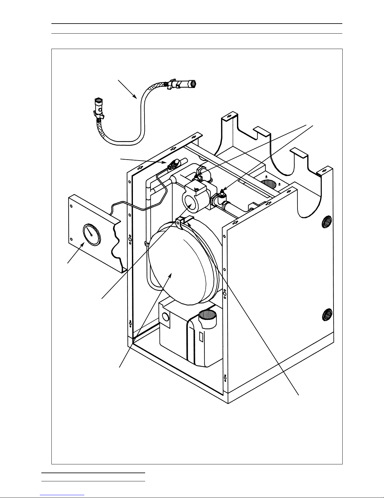
1:3 BOILER ARRANGEMENT
Fig. 1:3 Boulter Eco System Boiler Arrangement (12/19 shown)
TRANSIT BRACKET
4. CIRCULATING
PUMP
9. EXPANSION
VESSEL
1-3. FILLING LOOP
7. PRESSURE RELIEF VALVE
6. PRESSURE
GAUGE
PUMP
ISOLATING
VALVES
BOULTER BOILERS Eco-System PAGE 48
Page 51

Vessel Charge and bar 0.5 1 .0 1.5
Initial System
Pressure psi 7.3 14.5 21.8
Expansion
Vessel Total water content of system
size using expansion vessel supplied.
supplied
litres 125 90 62
gallons 27 19.7 13.6
litres 150 109 75
gallons 32.7 23.8 16.5
For systems having a larger
capacity multiply the total
system capacity by the factor to
obtain the total minimum
expansion vessel capacity
required.
1:4 SEALED SYSTEM COMPONENTS
1. Double Check Valve
Fitted to Cold Fill to prevent ‘back feed’
when Filling Loop is connected.
2. Filling Loop
A flexible hose which should ONLY be
connected when filling or topping up the
system.
THE FILLING LOOP HOSE MUST BE
DISCONNECTED AND MAY BE LEFT
HANGING FROM ONE OF THE FITTINGS
WHEN NOT IN USE.
3. Mains Water Shut Off Valve
Supplied to isolate mains supply.
4. Circulating Pump
The pump is fitted to the Flow Pipe as a
circulating pump for the Heating System.
5. Automatic Air Vent
The Vent automatically vents air from the
system.
The bleed screw should be loosened one
turn.
Routine venting of radiators is still advised.
6. Pressure Gauge
The Gauge (mounted behind the front door)
is provided as a visual indication of the
water pressure within the system.
When the system is initially filled (cold) and
all radiators full and vented, the Pressure
Gauge will show the Cold Fill Pressure. Set
the Red pointer to this setting.
Cold Fill Pressure ✎
A pressure below the set Cold Fill Pressure
indicates the system requires “topping up”.
7. Pressure Relief Valve
(fitted inside casing)
This can be fitted to one of the top sockets
of the Boiler. The remaining top socket
must be plugged.
8. Tundish
Supplied to provide a visual indication of
water flowing from the Relief Pressure Valve
(7). Refer to 2:3.
It is a requirement of G3 of the Building
Regulations that the Tundish is fitted in a
safe position visible to the householder.
9. Expansion Vessel
The Expansion Vessel is suitable for
systems with a static head of up to 5 metres
(16.5ft) i.e. the vertical distance between
expansion vessel and highest point of
system, usually the top of bedroom
radiators. If the static head is greater than 5
metres, then the charge in the vessel must
be increased to equal this higher static
pressure. The pressure can be increased if
required by simply pumping up the vessel
with a standard type pump and checking the
pressure with a tyre gauge with the system
at zero pressure. A schraider type valve is
provided on the vessel for this purpose (see
note below). During air charge, leave the
PRV open.
NOTE: The air charge should not exceed a
pressure of 1.5 bar (22 p.s.i.)
10. Expansion Vessel Requirements
Boiler
12/19
10 litres
19/26
12 litres
0.08 0.11 0.16
BOULTER BOILERS Eco-System PAGE 49
Page 52
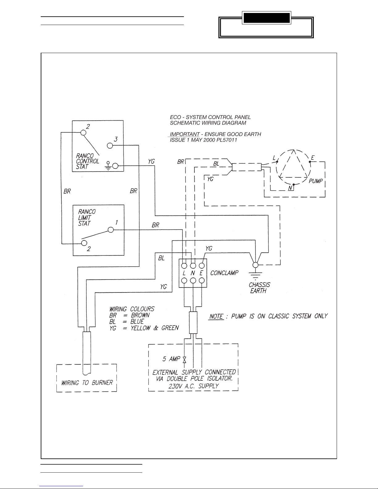
BOULTER BOILERS Eco-System PAGE 50
2:1 WIRING DIAGRAMS
IMPORTANT
ENSURE GOOD EARTH
ECO SEALED SYSTEM - CONTROL PANEL
SCHEMATIC WIRING DIAGRAM
Page 53
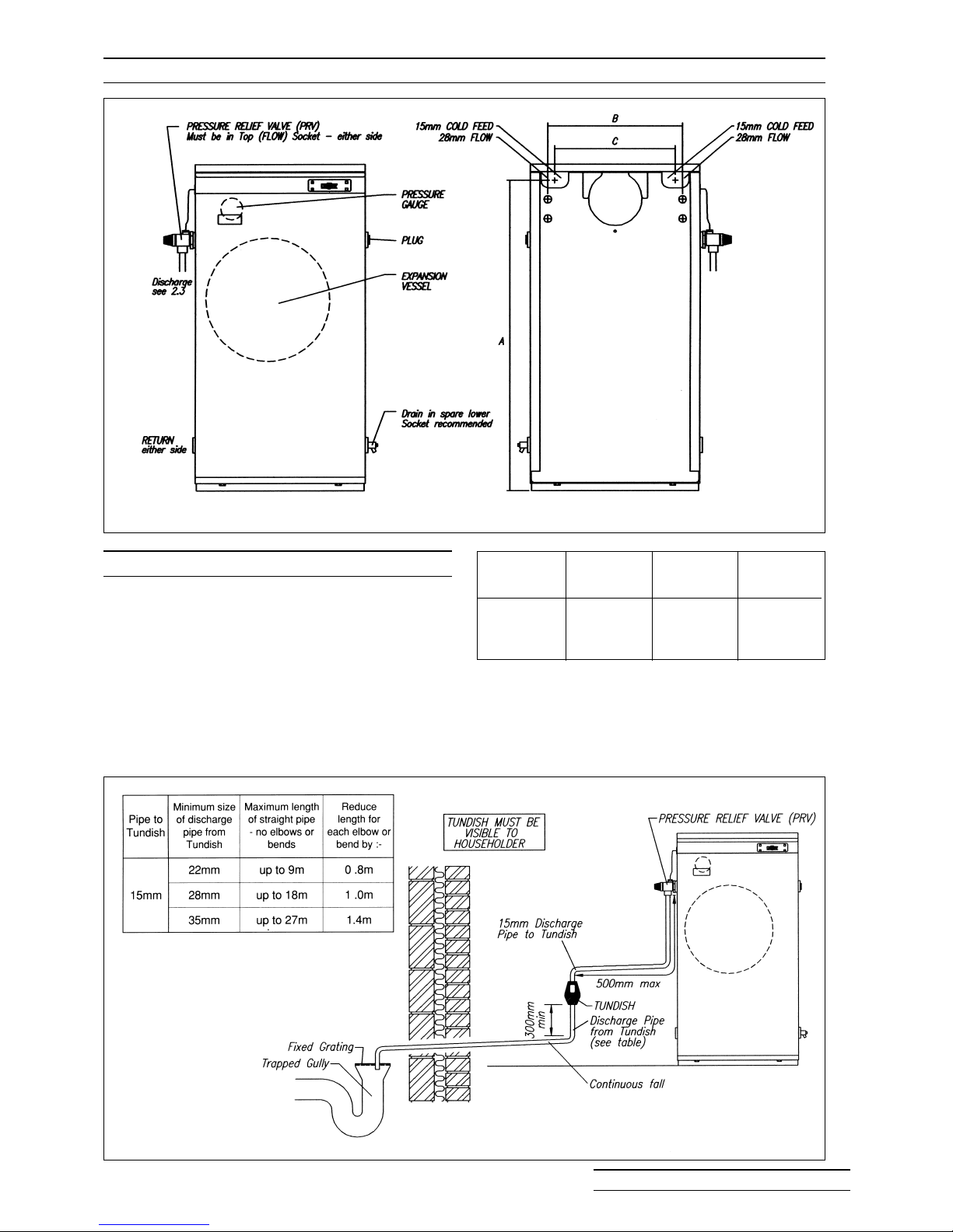
2:3 TUNDISH POSITION
2:2 SERVICE CONNECTIONS DIMENSIONS
A Tundish is supplied to provide a visual indication
of water flowing from the Pressure Relief Valve of
the Boiler.
The Tundish must be located in a position clearly
visible to the Householder.
Installation of the Tundish must comply with Part
G3 of The Building Regulations typically as fig.
2:3
FIG. 2:3 Tundish Installation
FIG. 2:2 Service Connections Dimensions
Model
12/19
19/26
ABC
815 354 317
BOULTER BOILERS Eco-System PAGE 51
&
Page 54
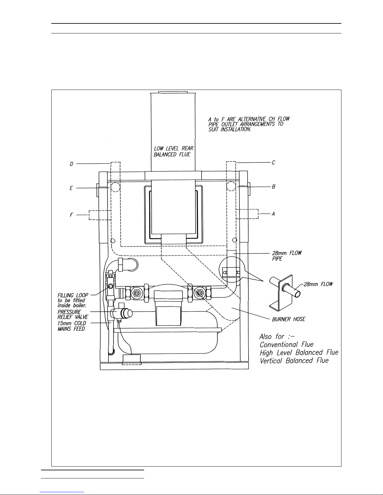
2:4 PIPE CONNECTION DETAILS
FIG. 2:4 Pipe Connection Details (12/19 shown)
NB Alternative locations for the PRV are shown in Figure 2.2 (Blank off existing position)
BOULTER BOILERS Eco-System PAGE 52
Page 55
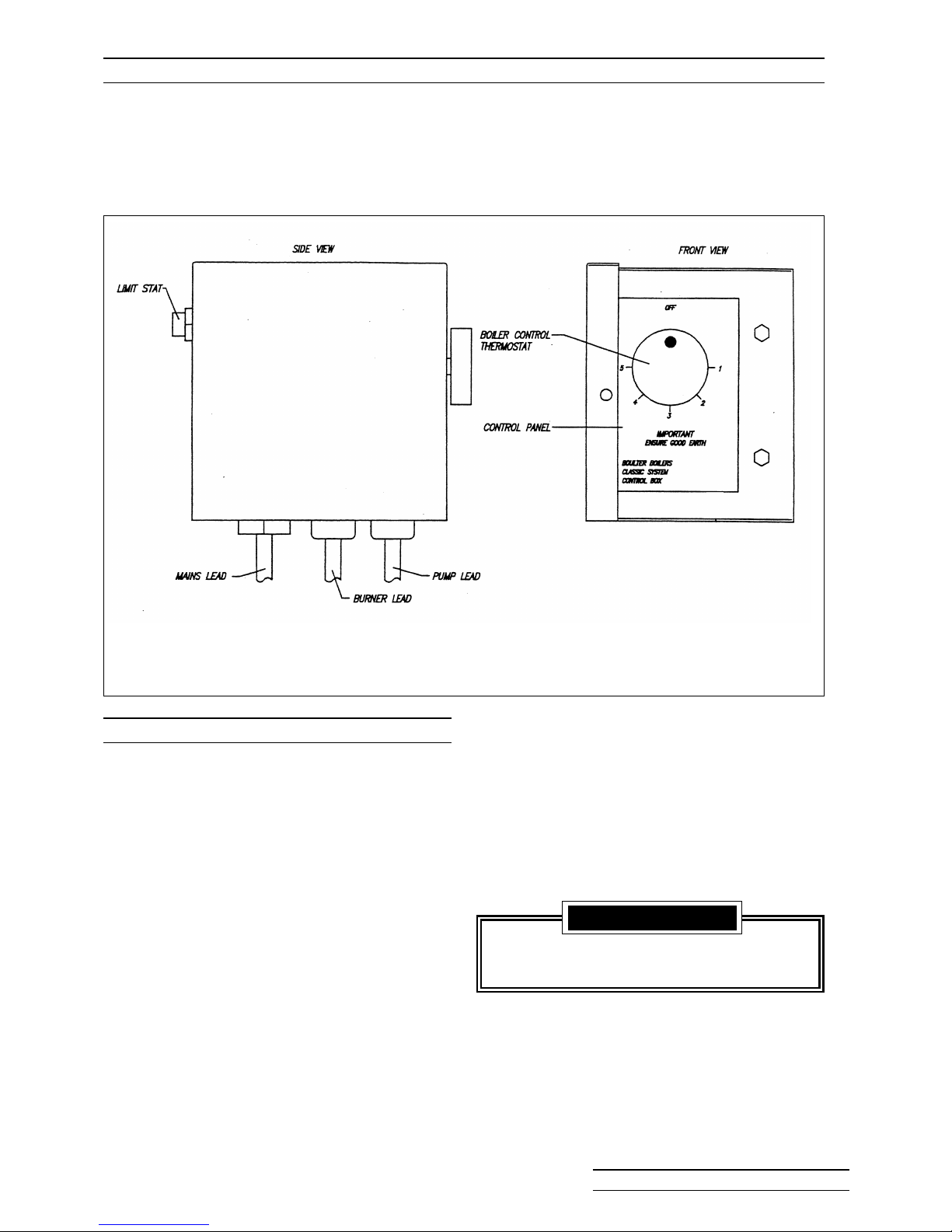
9. When the system is completely full and
vented close both Mains Isolating Valve and
Double Check Valve and disconnect flexible
Filling Loop Hose, catching water.
THE FILLING LOOP MUST BE
DISCONNECTED WHEN NOT IN USE.
10. Set the red pointer of the Pressure Gauge
to the Cold Fill pressure. Refer to 1:4.6.
1. Check that the black screw on the Automatic
Air Vent is loosened 1 turn.
2. Check spare sockets in Boiler have been
plugged.
3. Check drain cock/s are off.
4. Connect the Filling Loop Hose from the
incoming mains supply to the Double Check
Valve and open the Double Check Valve
fully.
5. Open the Mains Isolating Valve partway to
fill the system SLOWLY.
6. Flush system thoroughly and refill.
7. Vent radiator and any other manual Air
Release Vents.
8. Check for leaks particularly on an older
system which may have operated on a
lower pressure.
2:5 CONTROL PANEL
2:6 FILLING THE SYSTEM
IMPORTANT
Do not allow water in Filling Loop to
spill over the Burner.
FIG. 2:5 Control Panel
BOULTER BOILERS Eco-System PAGE 53
Page 56
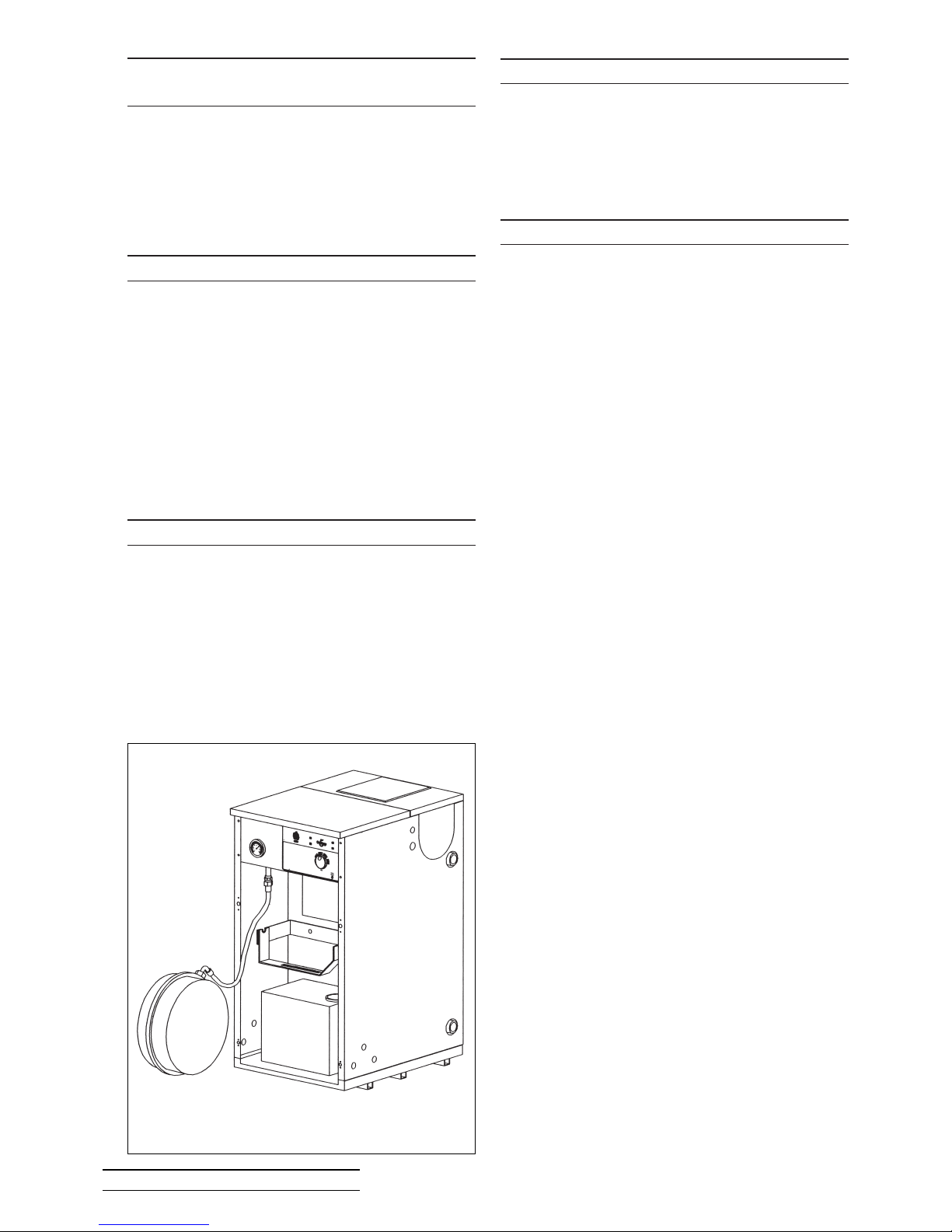
During routine servicing, the water should be
“topped up” if necessary using the Filling Loop
when the system is cold. Refer to 2:6 Filling the
System.
In addition to the General Boiler Maintenance
Manual, the following items should be checked on
an annual basis at the very least.
1. System Pressure
The System Pressure should be checked
periodically and increased as necessary
using the Filling Loop or other approved
method.
Filling should be carried out on a cold
system so that the pressure can be
increased to the original cold fill design
pressure (indicated by the red pointer on the
system Pressure Gauge).
The Pressure Gauge should be watched
carefully during filling and the Mains
Isolating Valve opened slowly.
2. System Draining
The Boiler as well as the system, is under
pressure and before disconnecting any
components, the system pressure must be
reduced. It is recommended that a suitable
drain be situated in one of the Boilers’ lower
sockets to facilitate this.
After replacing the relevant parts refill the
system as described in Section 2:6.
3. Pressure Relief Valve
This should be checked for operation during
annual servicing by increasing the system
pressure outlined in Section 2:7.
4. Expansion Vessel Pressure
Should be checked to be in accordance with
the cold design pressure of the system.
This is checked by allowing the water pressure to
increase until the valve operates - this should be
between 2.7 and 3.3 bar.
Reduce the system pressure to achieve the initial
cold fill pressure.
When the system water is heated, the pressure
will rise above the Cold Fill setting. If the pressure
reaches 2.5 bar when the Boiler is operated at its
highest temperature with all radiators in circulation,
then an additional expansion vessel must be fitted
in the system. Refer to Section 1 :4.9 and BS 7074
Part 1 for information on sizing of the additional
expansion vessel.
The design of the Sealed System Boiler enables
the Pressure Vessel to be lifted and laid on the
floor whilst still connected to the Boiler, enabling
full access to the Burner and Heat Exchanger.
Any work top must be removable for service
access to system components beneath the top
casing lid.
2:7 CHECK PRESSURE RELIEF VALVE
OPERATION
3:2 WATER SYSTEM
3:3 ADDITIONAL SERVICING
2:8 EXPANSION VESSEL PRESSURE
3:1 ACCESS
FIG. 3:1 Removing Expansion Vessel
BOULTER BOILERS Eco-System PAGE 54
Page 57

4:1 SEALED SYSTEM SPARE PARTS 12/19 & 19/26 BOILERS
Item
1
2
3
4
5
6
7
Double Check Valve
Filling Loop
Mains Water Shut Off Valve
Circulating Pump
Pressure Gauge
Pressure Relief Valve
Expansion Vessel (10l.)
1
1
1
1
1
1
1
207291
26775
BS 31004
EL 49012
206381
Part No.QtyDescription
Item
7
8
9
10
11
12
Expansion Vessel (12l.)
Flexible Hose c/w Washers
Expansion Vessel Bracket
Isolating Valve
1st Flow Pipe Assy.
2nd Flow Pipe Assy.
Tundish
1
1
1
2
1
1
1
BS 49010
99537
BS 49052C
BS 49051C
EL 49022
HE 49001C
207292
Part No.QtyDescription
3
4
10
1212
9
2
6
5
8
7
1
11
BOULTER BOILERS Eco-System PAGE 55
Page 58
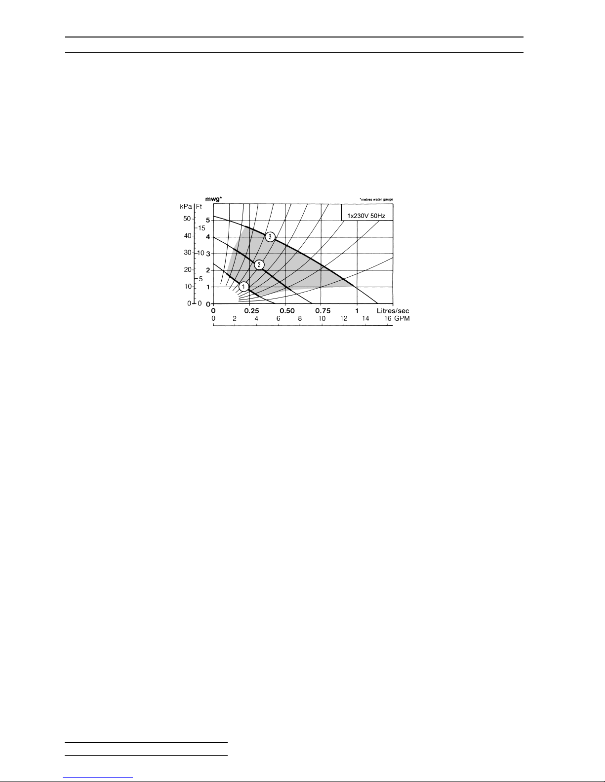
5:1 PUMP PERFORMANCE
Pump Performance on Eco Sealed System Boilers
The graphs below show the pump performance curves as defined by the pump manufacturer.
1. Set the speed selector switch to maximum (Speed 111) and switch on the
electricity supply and start the heating system.
2. Turn the switch to minimum (Speed 1) and if after a suitable time all the
radiators are not hot, increase the speed of the pump by switching to
Speed 11. Repeat this process until adequate circulation is achieved.
Remember, if the speed setting is too high, noise may be caused in the system
and the power consumption will be unnecessarily high.
BOULTER BOILERS Eco-System PAGE 56
Page 59

Indicates changes
from previous issue
Due to a policy of continual development Boulter Boilers reserves the right to alter or amend the design of its products without prior notice.
 Loading...