

FOR THE HOMEOWNER
Empire Comfort Systems has manufactured safe,
reliable heating systems since 1932. We take pride in our
reputation for quality products, backed by the best sales,
service and distribution network in this industry. These
replace models combine our proven technologies with
exceptional artistry and craftsmanship to add beauty and
warmth to any home.
There are several decorative options available for
your replace. Contact your Empire dealer for more
information.
CONTEMPORARY LINEAR
VENT-FREE GAS
FIREPLACE MODELS
VFLL60SP90L(N,P)-1

IMPORTANT INFORMATION
WARNING
Read and follow these safety precautions prior to operating
this appliance. Failure to follow these precautions may
result in death, injury, or property damage.
SAMPLES AND DEFINITIONS:
DANGER
Indicates a hazardous situation which, if not avoided, will
result in death or serious injury.
WARNING
Indicates a hazardous situation which, if not avoided, could
result in death or serious injury.
CAUTION
Indicates a hazardous situation which, if not avoided, could
result in minor or moderate injury.
NOTICE: Addresses practices not related to personal injury.
All correspondence should refer to complete Model Number,
Serial Number and type of gas. Fill out the Homeowner
Reference Section on page 8 in installation manual.
FOR THE HOMEOWNER
• Do not allow Combustible Materials adjacent to or in contact
with the replace. Combustible materials include wood,
compressed paper, plant bers, or other materials that will
burn. These materials are considered combustible even
when treated with re-retardant chemicals.
• Alert children and adults to the hazards of high surface
temperatures. Warn them to stay away to avoid burns and
clothing ignition.
• Supervise children when they are in the same room as the
replace.
• Do not place clothing or other ammable material on or near the
replace.
• Any safety screen or guard removed for servicing the replace
must be replaced prior to operating the replace.
• Keep replace area clear and free from combustible materials,
gasoline and other ammable vapors and liquids.
• Do not use this replace if any part has been under water.
Immediately call a qualied service technician to inspect the
replace and to replace any part of the control system and
any gas control which has been under water.
• Operate replace with all glass panels in place.
• Do not place embers (rock wool) in this replace.
• Do not place lava rocks in this replace.
TELEVISION CONSIDERATIONS
Installing a television above a replace has become increasingly
popular; however, the area above any replace gets hot and most
TV manufacturers recommend against placing their products
near a heat source.
If you install a television above this replace, Empire Comfort
Systems accepts no responsibility for damage or injuries. Follow
the television manufacturer’s installation instructions, including any
recommendations regarding proximity to heat sources.
If you have a TV above your replace, turn off the replace and let it
cool completely before servicing or touching any buttons on the TV.
MAINTENANCE AND SERVICE
Although the frequency of servicing and maintenance will depend
on use and the type of installation, you should have a qualied
service technician perform an appliance checkup at the beginning
of each heating season. Specic guidelines regarding each
appliance maintenance task are listed below.
NOTICE: It is normal for steel appliances to make expansion and/
or contraction noise during the start-up or cool-down cycle. Similar
noises are found with your furnace heat exchanger or car engine.
NOTICE: During manufacture, components of this replace
insert are treated with oils, lms or bonding agents. These are
not harmful, but may produce smoke and smells as they are
burned off during the initial operation of the replace insert. This
is normal. Open a window to ventilate the area.
Only glass approved for use by the manufacturer in replace may
be used for replacement. The glass replacement must be done
by a licensed or qualied service person.
WARNING
• Avoid breaking the glass.
• Do not operate this appliance without the glass panel
or with a broken glass panel.
• Replace only with Empire Comfort Systems parts.
CAUTION
Do not use Ammonia-based or abrasive cleaners on glass.
Do not attempt to clean glass when glass is hot.
COMBUSTIBLE MATERIAL
WARNING
Do not attach combustible material to the mantel of your
replace. This is a re hazard.
HEAT
FLOW
WARNING
This replace is not for use with solid fuels. Improper use
of the replace can cause serious injury or death from re,
burns, explosions or carbon monoxide poisoning.
Page 2 37353-0-0217
Figure 1

REMOVING & REPLACE THE GLASS FRONT
NOTICE: Spring tension inside the replace helps reduce glass
rattle. When you move the glass to the left, you will feel resistance.
REMOVING THE GLASS PANEL
1. Lift the glass panel up, slide it to the right, and then carefully
angle left side out of the slots. See Figure 2.
REPLACING THE GLASS PANEL
1. Place the right side of the glass panel into the slots in the
rebox. Carefully angle in the left side of the glass panel and
then slide the glass panel to the left. Settle the glass panel
into the slots by gently lowering it. See Figure 3.
TOP VIEW
GLASS
GLASS PANEL
TOP VIEW
GLASS PANEL
GLASS
Figure 2
37353-0-0217 Page 3
Figure 3

DECORATIVE GLASS & ROCK PLACEMENT
Decorative Crushed Glass is available in various colors, however
for the lighting system to be visible, use a clear style such as
clear frost, copper reective, or bronze reective. Add small
quantities of other colors as accents if desired
CAUTION
• Crushed glass and Glass droplets must not be more
than a single layer. Do not use more glass than
recommended.
• Never place media materials on or next to the burner.
• Use gloves and eye protection while applying the
decorative glass, droplets, ceramic logs or ceramic
rocks.
• Do not use real rocks or glass. Use decorative logs,
rocks and glass only from Empire Comfort Systems
and specically for the VFLL60SP.
• Keep the decorative media on the wire mesh support.
Do not restrict air ow.
1. Apply the crushed glass to the shaded area only. See Figure
4. Use enough to cover the oor of the replace, but do not
allow the media to reach higher than the ange surrounding
the burner. Never place decorative media inside the glass
panel surrounding the burner itself.
This replace uses crushed glass. Accent glass droplets (1/2
inch) or glass drops (1 inch), and ceramic ber logs, rocks
and pebbles. Mix colors and glass types, but do not exceed
the recommended amount of decorative media.
Figure 4
Quantity of Glass
Model Amount
VFLL60SP 4 square feet
Page 4 37353-0-0217

LIGHTING INSTRUCTIONS
FOR YOUR SAFETY READ BEFORE LIGHTING
WARNING
If you do not follow these instructions exactly, a re or explosion may result causing property damage,
personal injury or loss of life.
A. This appliance has a pilot which can be lit by hand or by
switching the remote receiver switch to the "ON" position.
When lighting the pilot, follow these instructions exactly.
B. Before lighting smell all around the appliance area for gas.
Be sure to smell next to the oor because some gas is
heavier than air and will settle on the oor.
What To Do If You Smell Gas
• Do not try to light any appliance.
• Do not touch any electrical switch;
• Do not use any phone in your building.
• Immediately call your gas supplier from a neighbor's
phone. Follow the gas supplier's instructions.
• If you cannot reach your gas supplier, call the re
department.
LIGHTING INSTRUCTIONS
1. STOP! Read the safety information above.
2. Turn OFF electric power to the appliance.
3. Turn gas shutoff valve counterclockwise to
On position.
4. Wait ten (10) minutes to clear out any gas. Then smell for
gas, including near the oor. If you smell gas, STOP! Follow
B in the safety information above on this page. If you do not
smell gas, go to the next step.
5. Turn ON electric power to the appliance.
6. Find pilot. The pilot is next to the burner.
7. Turn main ame to on. If the pilot does not light within 60
seconds, stop and go to Step 5.
C. If applicable, use only your hand to turn the gas shutoff valve
handle. Never use tools. If the handle will not turn by hand,
don't try to repair it; call a qualied service technician. Force
or attempted repair may result in a re or explosion.
D. Do not use this appliance if any part has been under water.
Immediately call a qualied service technician to inspect the
appliance and to replace any part of the control system and
any gas control which has been under water.
8. Refer to remote control instructions for detailed information,
control features, and operation. Notice: There is a CPI/
IPI switch for a continuous standing pilot mode or an
intermittent pilot mode. See appliance manual for location
of this switch. If the pilot or burner does not stay lit (in the
standing pilot mode), stop and immediately call a qualied
service technician or gas supplier.
9. If the burner or pilot does not operate properly after several
tries, turn the gas valve clockwise to OFF and call
your service technician or gas supplier.
10. Operation of the gas valve is controlled by a manual on/
off switch or a hand held remote control. Refer to remote
instructions for detailed operation information.
TO TURN OFF GAS TO FIREPLACE
1. Set REMOTE/OFF/ON switch to OFF.
2. Turn off all electric power to the appliance if service is to be
performed (if applicable).
37353-0-0217 Page 5
GAS SHUTOFF VALVE
3. Turn gas shutoff clockwise to OFF. Do not force.

Button
LED & FIREPLACE WALL CONTROLS
REMOTE
RECEIVER
SWITCH
BRIGHTNESS
LED BRIGHTNESS BUTTON
Press the LED Brightness Button to activate the LED lights and
to switch the LED Intensity to High, Medium, Low or Off.
1 – On – High
2 – Medium
3 – Low
4 – Off
Use the Brightness Button in conjunction with the Mode Button to
create unique looks.
If no change is made to the LED lights, they will turn off
automatically after two hours.
Lights will remember the last Mode when turned on again. (After
a power failure, you must reset the lights to the desired Mode.)
Turn off the LED Lights when not in use.
LED MODE BUTTON
Press the Mode Button to switch LED light system from
Automatic Color Changes to Individual Colors.
1 – Auto-cycle – Rapid
2 – Auto-cycle – Gradual
3 – Pause Auto-cycle
4 – Deep Blue
5 – Royal Violet
6 – Cardinal Red
7 – Sea Green
8 – Forest Green
9 – Tranquil Blue
10 – White
NOTICE: LED lights will automatically turn off after two hours.
LED
BUTTON
- High
- ON
- REMOTE
- OFF
- Medium
- Low
- OFF
LED MODE
BUTTON
Figure 5
USING THE REMOTE CONTROL
CAUTION
The transmitter and receiver are radio frequency devices.
Placing the receiver in or near metal may severely reduce
the signal range.
NOTICE:
• Turn OFF the main gas supply of the replace during
installation or maintenance of the receiver.
• Place the receiver's 3-position slider switch in the OFF
position during installation or maintenance.
WARNING
Fire Hazard. The receiver lights the replace, which can
turn on suddenly. Keep away from the replace burner
when operating the remote system or activating manual
bypass of the remote system.
WARNING
Property Damage Hazard. Excessive heat can cause property
damage. The replace can stay lit for many hours. Turn off
the replace if it is not going to be attended for any length
of time.
TRANSMITTER (REMOTE CONTROL WITH LCD DISPLAY)
The Proame Transmitter uses a streamline design with a simple
button layout and informative LCD display. See Figure 6.
The Transmitter is powered by 3 AAA type batteries. A Mode
Button is provided to Index between the features and a
Thermostat Button is used to turn on/off or index through
thermostat functions. See Figures 6 and 7.
Blue LCD Display
ON/OFF Button
THERMOSTAT
UP/DOWN Arrow Button
MODE Button
Figure 6 - Proame Transmitter (Remote Control)
WARNING
Always place the Transmitter where children can not reach it.
Page 6 37353-0-0217
Figure 7 - Transmitter LCD display

USING THE REMOTE CONTROL (CONT'D)
INITIALIZING THE SYSTEM
Install 4 AA batteries into the receiver located behind the wall
plate. See Figure 5. Note the polarity of battery and insert into
the battery bay as indicated on the Battery cover (+/-). Place the
3 position slider switch in the Remote position.
Insert paper clip, or other similar object into the hole marked PRG
on the receiver front cover. The receiver will beep three times to
indicate that it is ready to synchronize with a transmitter. Install
the 3 AAA type batteries in the transmitter. Push the ON button.
The receiver will beep four times to indicate the transmitter’s
command is accepted and sets to the particular code of that
transmitter. The system is now initialized.
TEMPERATURE INDICATION DISPLAY
With the system OFF, press the Thermostat Button and the Mode
Button at the same time. Verify that a C or F is visible to the right
of the Room Temperature display. See Figures 8 and 9.
TURN ON THE FIREPLACE
Press the ON/OFF Button. The Transmitter display will show all
active Icons on the screen. The replace main burner turns on.
A single beep from the Receiver will conrm reception of the
command.
TURN OFF THE FIREPLACE
Press the ON/OFF Button on the Transmitter. The Transmitter
LCD display will only show the room temperature and Icon. See
Figure 10. The replace burner turns off. A single beep from the
Receiver conrms reception of the command.
Figure 10
Figure 8 - Fahrenheit
Figure 9 - Celsius
37353-0-0217 Page 7

USING THE REMOTE CONTROL (CONT'D)
REMOTE FLAME CONTROL
The remote has six ame levels. With the system on, and the
ame level at maximum, each time you press the down arrow
button will reduce the ame height by one step until the ame is
turned off. Pushing the up arrow button will increase the ame
height each time it is pressed. Pushing the up arrow button while
the system is on but the ame is off will light the burner, the ame
will come on in the high position. See Figures 11 and 12. A
single beep conrms receipt of the command.
Figure 11
Figure 13
Figure 12
Figure 14
Page 8 37353-0-0217
USING THE REMOTE CONTROL (CONT'D)
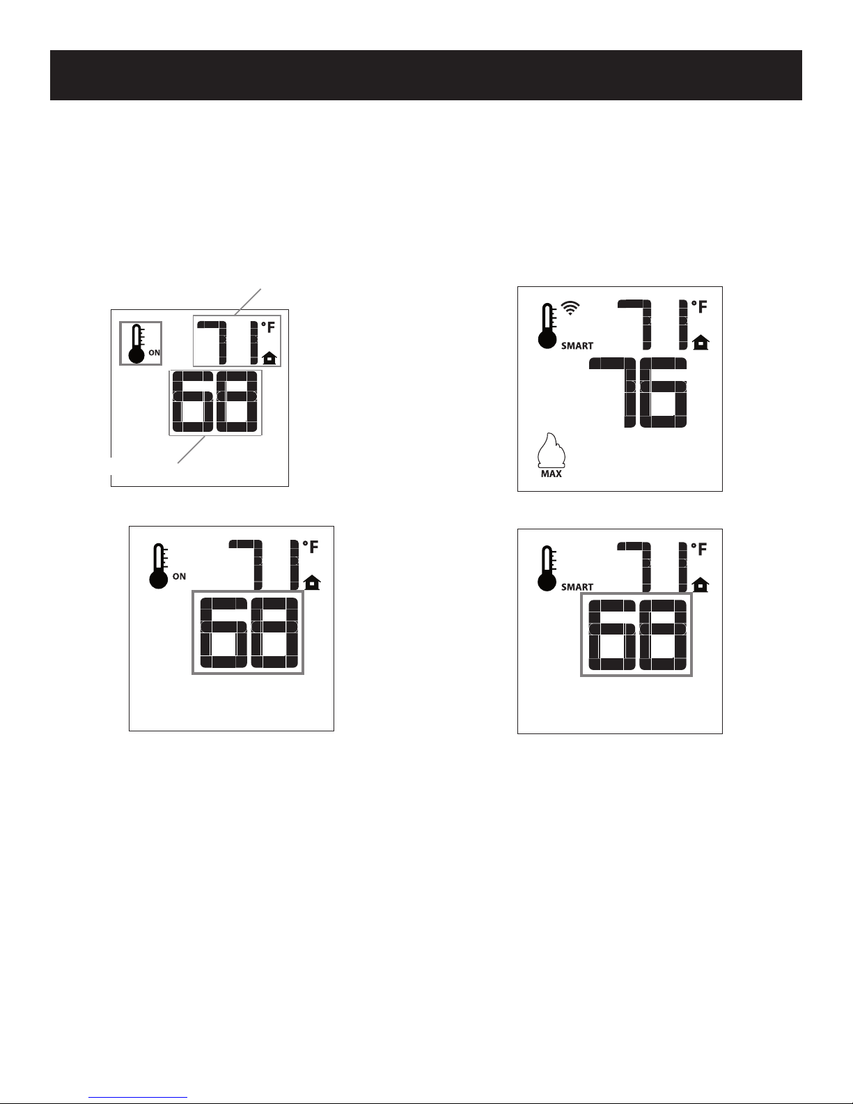
THERMOSTAT OPERATION
The Remote Control can operate as a room thermostat. The
thermostat can be set to a desired temperature to control the
comfort level in a room.
To activate this function, press the Thermostat Button. See
Figure 6. The LCD display on the Transmitter will change to
show that the room thermostat is ON and the set temperature
is now displayed. See Figures 15 and 16. To adjust the set
temperature, press the Up or Down Arrow Buttons until the
desired set temperature is displayed on the LCD screen of the
Transmitter.
ROOM TEMPERATURE
SET TEMPERATURE
Figure 15
SMART THERMOSTAT (TRANSMITTER OPERATION)
The Smart Thermostat function adjusts the ame height in
accordance to the difference between the set point temperature
and the actual room temperatures. As the room temperature
gets closer to the set point the Smart Function will modulate the
ame down.
To activate this function, press the Thermostat Button (Figure 6)
until the word SMART appears to the right of the temperature bulb
graphic. See Figure 17. To adjust the set temperature, press the
Up or Down arrow Buttons until the desired set point temperature
is displayed on the LCD screen of the Transmitter. See Figure 18.
Figure 17
Figure 16
37353-0-0217 Page 9
Figure 18

USING THE REMOTE CONTROL (CONT'D)
REMOTE
RECEIVER
SWITCH
BRIGHTNESS
BUTTON LOCK
This function will lock the buttons to prevent unsupervised
operation.
To lock the remote, press the MODE and the UP arrow button at
the same time. See Figure 19.
To unlock the remote, press the MODE and the UP arrow button
at the same time.
Figure 19
LOW POWER BATTERY INDICATOR TRANSMITTER
When the Transmitter batteries are low, a battery icon will appear
on the LCD display. See Figure 20. Replace the batteries and
the Icon will disappear. See page 11 to change batteries in
remote switch.
RECEIVER
When the receiver batteries are low, no beep will be emitted
when it receives an ON/OFF command from the transmitter.
Replace the batteries.
MANUAL BYPASS OF THE REMOTE SYSTEM
If the batteries of the receiver or transmitter die, you can still
operate the replace manually by sliding the three position slider
switch on the wall control to the ON position.
This will bypass the remote control feature of the system and the
replace main burner will come on.
LED
BUTTON
- High
- ON
- REMOTE
- OFF
- Medium
- Low
- OFF
LED MODE
BUTTON
Figure 21
Figure 20
Page 10 37353-0-0217

REMOTE
CLEANING AND SERVICE
Annual inspection and cleaning by your dealer or qualied
service technician is recommended to prevent malfunction.
TURN OFF FIREPLACE AND ALLOW TO COOL BEFORE
CLEANING.
Remove any optional decorative covers or decorative glass
material. Gloves are recommended.
PERIODIC CLEANING - Refer to parts diagram for location of
items discussed below.
• Do not use cleaning uid to clean any part of replace.
• Clean glass with ammonia-free cleaner. Ammonia will etch or
stain glass when heated.
• Remove loose particles and dust from the burner, controls
and air shutter.
• Inspect and clean burner air intake hole. Remove lint or
particles with brush. Failure to keep air intake hole clean will
result in sooting and poor combustion.
ANNUAL CLEANING/INSPECTION - Refer to parts diagram
for location of items discussed below.
• Inspect and clean burner air intake hole. Remove lint or
particles with vacuum or brush. Failure to keep air intake
hole clean will result in sooting and poor combustion.
• Inspect and clean all burner ports.
• Inspect ODS pilot for operation and accumulation of lint at air
intake holes.
• Verify ame pattern for proper operation.
• Verify smooth and responsive ignition of main burner.
PILOT MAINTENANCE AND CLEANING
Oxygen Depletion Sensor Pilot
When the pilot has a large yellow tip ame, clean the Oxygen
Depletion Sensor as follows:
1. Use canned air to blow through hole A. See Figure 22.
This will blow out foreign materials such as dust, lint and
spider webs.
C
2. If intermittent pilot replace stops working, clean ame
sensor B (Figure 22) with a damp cloth.
3. If intermittent pilot ignitor does not spark, clean ignitor C
(Figure 65) with a damp cloth.
CONTROL COMPARTMENT AND BURNER MAINTENANCE
Keep the control compartment and burner area clean by
vacuuming or brushing area at least twice a year.
WARNING
The replace can get very hot. Handle only when cool.
Always turn off gas to the pilot before cleaning. For relighting,
refer to lighting instructions located on the rating plate.
Never obstruct the ow of the combustion and ventilation air.
Keep the front of the replace clear of all obstacles.
BATTERY REPLACEMENT
An intermittent pilot may require more frequent battery changes.
To replace the batteries, follow these steps:
1. Remove the cover from the electrical box on the wall.
2. Replace the batteries inside the box.
3. Replace the cover using four (4) #4 x 1/2 Phillips screws.
SWITCH
B
INTERMITTENT PILOT
Figure 22
WARNING
Never use needles, wires, or similar cylindrical objects to
clean the pilot to avoid damaging the calibrated ruby that
controls the gas ow.
37353-0-0217 Page 11
LED SWITCH
ON-OFF
LED SWITCH
COLOR MODE
A
COVER PLATE
Figure 23

WARRANTY
Empire Comfort Systems Inc. warranties this hearth
product to be free from defects at the time of purchase and
for the periods specied below. Hearth products must be
installed by a qualied technician and must be maintained
and operated safely, in accordance with the instructions
in the owner’s manual. Empire will not warranty any
Boulevard replace that is not installed by the selling
dealer or that dealer’s direct contract agents.
This warranty applies to the original purchaser only
and is not transferable. All warranty repairs must be
accomplished by a qualied gas appliance technician.
Limited Lifetime Parts Warranty with a Five-Year
Limited Labor Warranty – Combustion Chamber and
Heat Exchanger
• If the combustion chamber or heat exchanger (see
parts list) fails because of defective workmanship or
material, Empire will repair or replace at Empire’s
option.
• Within ve years from the date of purchase, Empire
will pay reasonable labor to have the defective part
repaired or replaced at Empire’s option.
Limited Five-Year Parts & Labor Warranty – All Other
Components
(Except Remote Controls, Thermostats, Lights,
Accessories and Replacement Parts)
• Should any part fail because of defective workmanship
or material within ve years from the date of purchase,
Empire will repair or replace at Empire’s option.
• Within ve years from the date of purchase, Empire
will pay reasonable labor to have that defect repaired
at Empire’s option.
Limited One-Year Parts Warranty – Remote Controls,
Thermostats, Lights, Accessories, and Replacement
Parts
• Should any remote control, thermostat, lighting system
component, replacement part fail because of defective
workmanship within one year from the date of purchase,
Empire will repair or replace at Empire’s option.
Duties Of The Owner
• The appliance must be installed by a qualied installer
and operated in accordance with the instructions
furnished with the appliance.
• A bill of sale, cancelled check, or payment record
should be kept to verify purchase date and establish
warranty period.
• Ready access to the appliance for service.
What Is Not Covered
• Damages that might result from the use, misuse, or
improper installation of this appliance. Travel,
diagnostic costs and freight charges on warranted
parts to and from the factory.
• Claims that do not involve defective workmanship or
materials.
• Unauthorized service or parts replacements.
• Removal and reinstallation cost.
• Inoperable due to improper or lack of maintenance.
How To Get Service
• To make a claim under this warranty, please have your
receipt available and contact your installing dealer.
Provide the dealer with the model number, serial
number, type of gas, and purchase verication. The
installing dealer is responsible for providing service
and will contact the factory to initiate any warranted
parts replacements. Empire will make replacement
parts available at the factory. Shipping expenses are
not covered.
• If, after contacting your Empire dealer, service
received has not been satisfactory, contact: Consumer
Relations Department, Empire Comfort Systems Inc.,
PO Box 529, Belleville, Illinois 62222, or send an
e-mail to info@empirecomfort.com with Consumer
Relations in the subject line.
Your Rights Under State Law
• This warranty gives you specic legal rights, and you
may also have other rights, which vary from state to
state.
Empire Comfort Systems Inc.
Belleville, IL
If you have a general question
about our products, please e-mail
us at info@empirecomfort.com.
If you have a service or repair
question, please contact your dealer.
www.empirecomfort.com
37353-0-0217
 Loading...