

Page 1
Page 2

Boulder
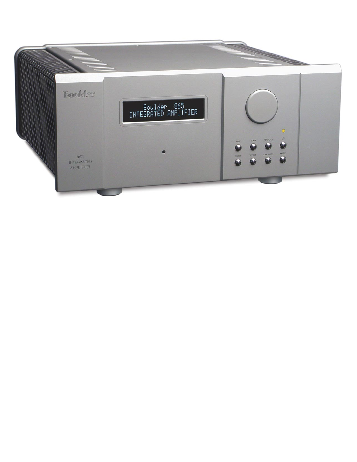
865 Integrated Amplifier
Instruction Manual
10/1/07
Boulder Amplifiers, Inc.
3235 Prairie Ave.
Boulder, CO 80301
www.boulderamp.com
APPENDIX RECORDING
BOULDER
LINK
PROGRAMMING
REMOTE
CONTROL OPERATION
GETTING
STARTED
Page 3
L L
R R
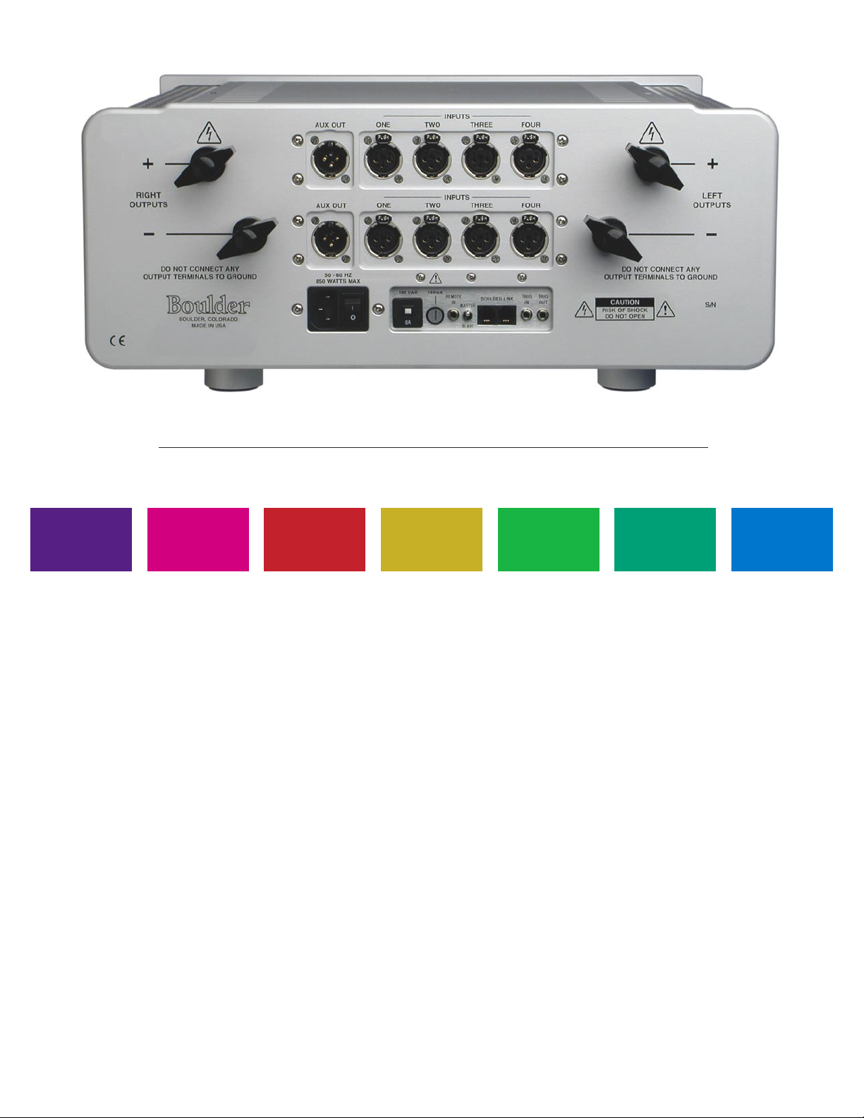
B o u l d e r 8 6 5 I n t e g r a t e d A m p l i f i e r R e a r P a n e l
APPENDIX RECORDING
BOULDER
LINK
PROGRAMMING
REMOTE
CONTROL OPERATION
GETTING
STARTED
Page 4

GETTING STARTED
Introduction . . . . . . . . . . . . . . . . . . . . . . . . . . . . . . . . . . . . . . . . . . . . . . . . . . . . . . . . . . . . . . . 1-1
Quick Start . . . . . . . . . . . . . . . . . . . . . . . . . . . . . . . . . . . . . . . . . . . . . . . . . . . . . . . . . . . . . . . . 1-1
Placement of the 865 Integrated Amplifier . . . . . . . . . . . . . . . . . . . . . . . . . . . . . . . . . . . . . 1-2
Connecting to the Mains Outlet . . . . . . . . . . . . . . . . . . . . . . . . . . . . . . . . . . . . . . . . . . . . . . 1-3
Polarity . . . . . . . . . . . . . . . . . . . . . . . . . . . . . . . . . . . . . . . . . . . . . . . . . . . . . . . . . . . . . . . . . . . 1-4
Connecting a Balanced Source. . . . . . . . . . . . . . . . . . . . . . . . . . . . . . . . . . . . . . . . . . . . . . . . 1-4
Connecting an Unbalanced Source. . . . . . . . . . . . . . . . . . . . . . . . . . . . . . . . . . . . . . . . . . . . 1-5
Connecting the Auxiliary Outputs . . . . . . . . . . . . . . . . . . . . . . . . . . . . . . . . . . . . . . . . . . . . 1-6
Connecting the Auxiliary Outputs to a Component with Balanced Inputs. . . . . . . . . . 1-6
Connecting the Auxiliary Outputs to a Component with Unbalanced Inputs . . . . . . . 1-7
Polarity . . . . . . . . . . . . . . . . . . . . . . . . . . . . . . . . . . . . . . . . . . . . . . . . . . . . . . . . . . . . . . . . . . . 1-8
Connecting Your Loudspeakers . . . . . . . . . . . . . . . . . . . . . . . . . . . . . . . . . . . . . . . . . . . . . . 1-8
Setting the Boulderlink Switch . . . . . . . . . . . . . . . . . . . . . . . . . . . . . . . . . . . . . . . . . . . . . . . 1-9
OPERATION
Powering Up. . . . . . . . . . . . . . . . . . . . . . . . . . . . . . . . . . . . . . . . . . . . . . . . . . . . . . . . . . . . . . . 2-1
Input Selections . . . . . . . . . . . . . . . . . . . . . . . . . . . . . . . . . . . . . . . . . . . . . . . . . . . . . . . . . . . . 2-2
Volume. . . . . . . . . . . . . . . . . . . . . . . . . . . . . . . . . . . . . . . . . . . . . . . . . . . . . . . . . . . . . . . . . . . . 2-3
Balance. . . . . . . . . . . . . . . . . . . . . . . . . . . . . . . . . . . . . . . . . . . . . . . . . . . . . . . . . . . . . . . . . . . . 2-4
Mute. . . . . . . . . . . . . . . . . . . . . . . . . . . . . . . . . . . . . . . . . . . . . . . . . . . . . . . . . . . . . . . . . . . . . . 2-5
Display. . . . . . . . . . . . . . . . . . . . . . . . . . . . . . . . . . . . . . . . . . . . . . . . . . . . . . . . . . . . . . . . . . . . 2-6
TABLE OF CONTENTS
APPENDIX RECORDING
BOULDER
LINK
PROGRAMMING
REMOTE
CONTROL OPERATION
GETTING
STARTED
Page 5

REMOTE CONTROL
Batteries. . . . . . . . . . . . . . . . . . . . . . . . . . . . . . . . . . . . . . . . . . . . . . . . . . . . . . . . . . . . . . . . . . . 3-1
Source Selection . . . . . . . . . . . . . . . . . . . . . . . . . . . . . . . . . . . . . . . . . . . . . . . . . . . . . . . . . . . . 3-2
Volume, Balance and Mute. . . . . . . . . . . . . . . . . . . . . . . . . . . . . . . . . . . . . . . . . . . . . . . . . . . 3-2
PROGRAMMING
Input Names . . . . . . . . . . . . . . . . . . . . . . . . . . . . . . . . . . . . . . . . . . . . . . . . . . . . . . . . . . . . . . . 4-1
Input Level Calibration. . . . . . . . . . . . . . . . . . . . . . . . . . . . . . . . . . . . . . . . . . . . . . . . . . . . . . 4-3
Input Balance Calibration. . . . . . . . . . . . . . . . . . . . . . . . . . . . . . . . . . . . . . . . . . . . . . . . . . . . 4-4
Theater Mode . . . . . . . . . . . . . . . . . . . . . . . . . . . . . . . . . . . . . . . . . . . . . . . . . . . . . . . . . . . . . . 4-5
Start Volume . . . . . . . . . . . . . . . . . . . . . . . . . . . . . . . . . . . . . . . . . . . . . . . . . . . . . . . . . . . . . . . 4-5
Programming by the Display Button . . . . . . . . . . . . . . . . . . . . . . . . . . . . . . . . . . . . . . . . . . 4-6
Auxiliary Outputs Mode . . . . . . . . . . . . . . . . . . . . . . . . . . . . . . . . . . . . . . . . . . . . . . . . . . . . 4-6
Boulderlink ID . . . . . . . . . . . . . . . . . . . . . . . . . . . . . . . . . . . . . . . . . . . . . . . . . . . . . . . . . . . . . 4-7
Remote ID . . . . . . . . . . . . . . . . . . . . . . . . . . . . . . . . . . . . . . . . . . . . . . . . . . . . . . . . . . . . . . . . . 4-7
Boulderlink Speed . . . . . . . . . . . . . . . . . . . . . . . . . . . . . . . . . . . . . . . . . . . . . . . . . . . . . . . . . . 4-7
Reset to Factory Defaults . . . . . . . . . . . . . . . . . . . . . . . . . . . . . . . . . . . . . . . . . . . . . . . . . . . . 4-8
APPENDIX RECORDING
BOULDER
LINK
PROGRAMMING
REMOTE
CONTROL OPERATION
GETTING
STARTED
Page 6

BOULDERLINK
Connecting the Boulderlink . . . . . . . . . . . . . . . . . . . . . . . . . . . . . . . . . . . . . . . . . . . . . . . . . . 5-1
Connecting 800 Series to 1000 or 2000 Series with Boulderlink. . . . . . . . . . . . . . . . . . . . 5-2
Setting Boulderlink Switches . . . . . . . . . . . . . . . . . . . . . . . . . . . . . . . . . . . . . . . . . . . . . . . . . 5-3
Setting Boulderlink ID Numbers. . . . . . . . . . . . . . . . . . . . . . . . . . . . . . . . . . . . . . . . . . . . . . 5-3
Power up via Boulderlink . . . . . . . . . . . . . . . . . . . . . . . . . . . . . . . . . . . . . . . . . . . . . . . . . . . 5-4
Boulderlink Messages . . . . . . . . . . . . . . . . . . . . . . . . . . . . . . . . . . . . . . . . . . . . . . . . . . . . . . . 5-6
RECORDING
Connecting a Recording Device . . . . . . . . . . . . . . . . . . . . . . . . . . . . . . . . . . . . . . . . . . . . . . 6-1
APPENDIX
Block Diagram . . . . . . . . . . . . . . . . . . . . . . . . . . . . . . . . . . . . . . . . . . . . . . . . . . . . . . . . . . . . . 7-1
Specifications . . . . . . . . . . . . . . . . . . . . . . . . . . . . . . . . . . . . . . . . . . . . . . . . . . . . . . . . . . . . . . 7-2
Troubleshooting . . . . . . . . . . . . . . . . . . . . . . . . . . . . . . . . . . . . . . . . . . . . . . . . . . . . . . . . . . . . 7-3
Notes . . . . . . . . . . . . . . . . . . . . . . . . . . . . . . . . . . . . . . . . . . . . . . . . . . . . . . . . . . . . . . . . . . . . . 7-4
APPENDIX RECORDING
BOULDER
LINK
PROGRAMMING
REMOTE
CONTROL OPERATION
GETTING
STARTED
Page 7
GE TTI NG START E D
INTRODUCTION
Congratulations on your selection of the Boulder 865 Integrated
Amplifier, the finest integrated amplifier in the world. We at Boulder are
certain it will provide years of listening pleasure.
QUICK START
To get started listening, you will need to connect the 865 as both an
amplifier and preamplifier. Please take note of the following.
WARNING: Because the volume control is connected optically, it
has no stops and it is tempting to spin it. DO THIS ONLY WITH THE
POWER OFF! It must be given the respect you would any other volume
control, as it has the ability to get loud very quickly. By the time you have
turned it up to -40.0 dB with a source turned on, you should be hearing
some music. If not, do not increase the volume until you have solved
this problem. See the troubleshooting section on page 7-3.
For the 865 to work properly, the Boulderlink MASTER/SLAVE
switch should be set to MASTER in most instances. See page 1-9.
A thorough reading of this manual prior to use and set up will
greatly enhance your enjoyment of the 865 Integrated Amplifier.
1-1
GETTING
STARTED
Page 8

PLACEMENT OF THE 865 INTEGRATED AMPLIFIER
Your Boulder 865 Integrated Amplifier is designed to reduce the
effects that external magnetic and radio fields (RF) have on its internal
circuitry. While placement is not critical, known magnetic fields should
be avoided. Line of sight from the listening position is necessary for the
remote control to function properly.
Because the 865 is heavy, a solid, stable surface should be used. As
it will generate heat, there should be good air circulation around the
heatsinks.
You may want to maintain access to the rear panel for cable
changes.
1-2
GETTING
STARTED
Page 9
CONNECTING TO THE MAINS OUTLET
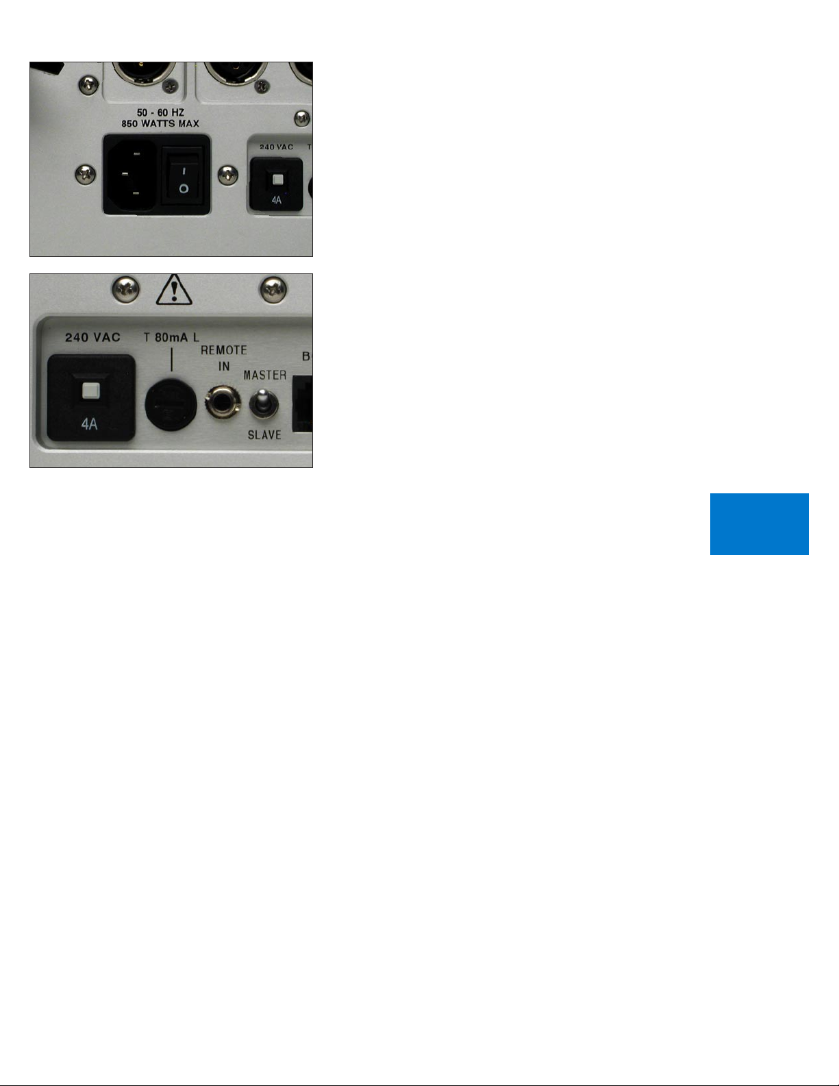
Your 865 Integrated Amplifier is supplied with a mains power cord
suitable for the location where it was purchased. It is constructed of a
large enough wire gauge and a cable plug appropriate for the mains
voltage in your location. Do not substitute another power cable.
The exact voltage and frequency range is indicated on the rear
panel. Make certain that the mains voltage in your area is within the
specifications shown.
WARNING: If the voltage shown on the 865 rear panel is not the
same as the voltage in your area, DO NOT connect the amplifier to AC
mains. CONTACT YOUR DEALER IMMEDIATELY.
Once the 865 is connected to a live mains outlet and the mains
power switch is turned on, the front panel indicator will be illuminated.
The indicator will be of varying color, showing that the supervising
microprocessor is powered up and ready.
1-3
GETTING
STARTED
Page 10
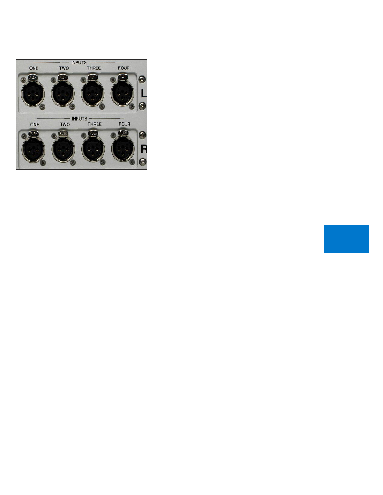
POLARITY
Please note that the 865 Integrated Amplifier conforms to the
standard of Pin 2 as the positive or ”hot” pin for all analog balanced
inputs and outputs.
CONNECTING A BALANCED ANALOG SOURCE
To realize the greatest sonic potential of your 865 Integrated Amplifier,
use balanced connections whenever possible. Balanced cables reduce
interference from magnetic and RF sources to an absolute minimum.
Connect each line source to one of the four inputs provided. Later,
you will be able to program each input with the source’s name, so you
may want to make a list as you connect them.
1-4
GETTING
STARTED
Page 11
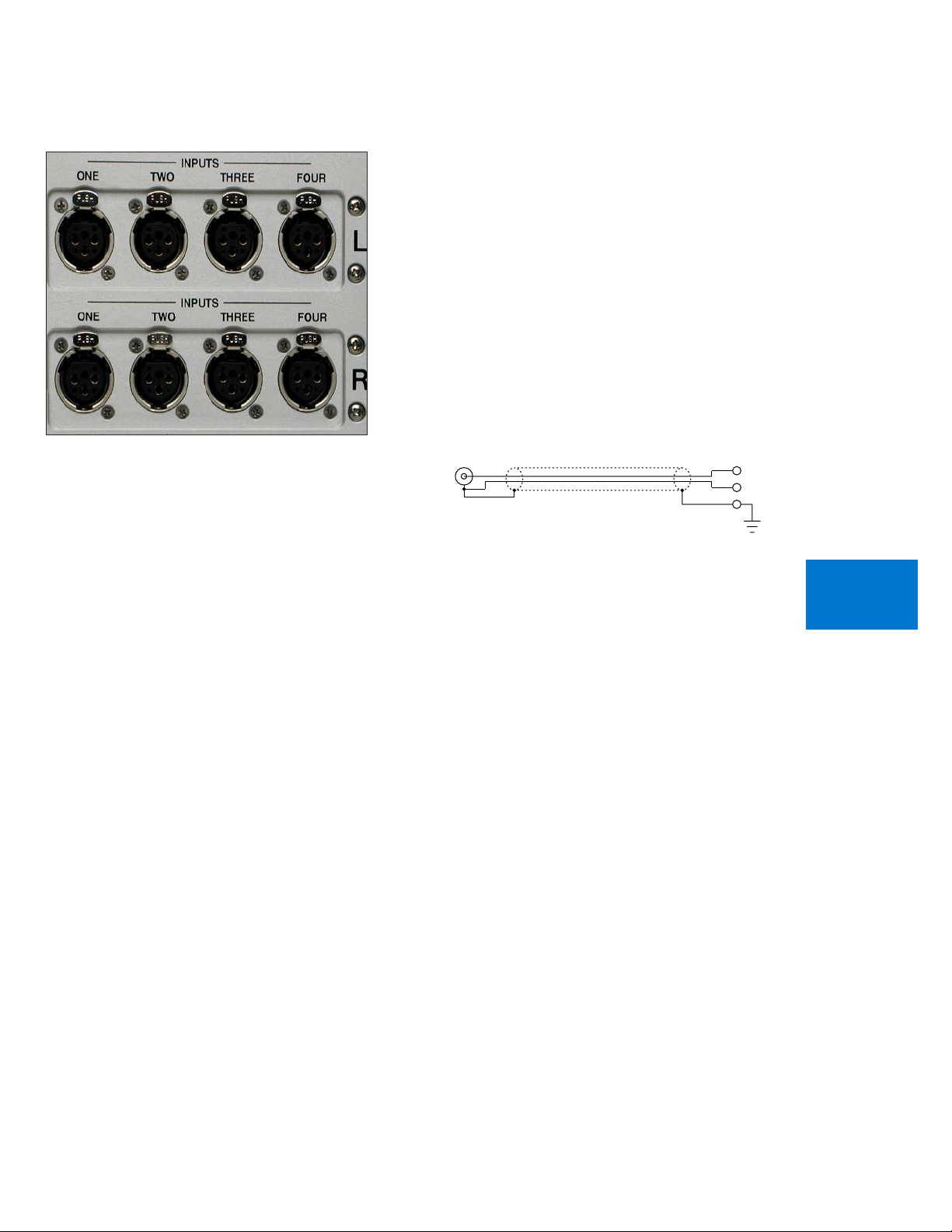
CONNECTING AN UNBALANCED SOURCE
UNBALANCED INPUT CABLE
3-NEG INPUT
2-POS INPUT
1-GROUND
Although the inputs are all of the 3-pin XLR type, an unbalanced
source is easily accommodated by using a special cable. This cable has
an RCA phono type connector on the source end and a 3-pin connector
(for an input) at the 865 Integrated Amplifier.
The negative input (Pin 3) should be wired to ground only at the
RCA phono connector. This brings the negative input reference of the
865 to the unbalanced source ground, thus reducing ground loops.
Another option for accommodating unbalanced sources is that of
the Boulder ABL2 input adapter. It converts a balanced XLR input into
a RCA connector input right at the rear of the 865. Please contact your
dealer for information regarding the ABL2 Input Adapter.
Like the above cable, the negative input of the 865 is connected to
the ground of the RCA connector. However, this negative side will then
share the shield wire with the chassis ground and will not have the best
hum rejection.
1-5
GETTING
STARTED
Page 12
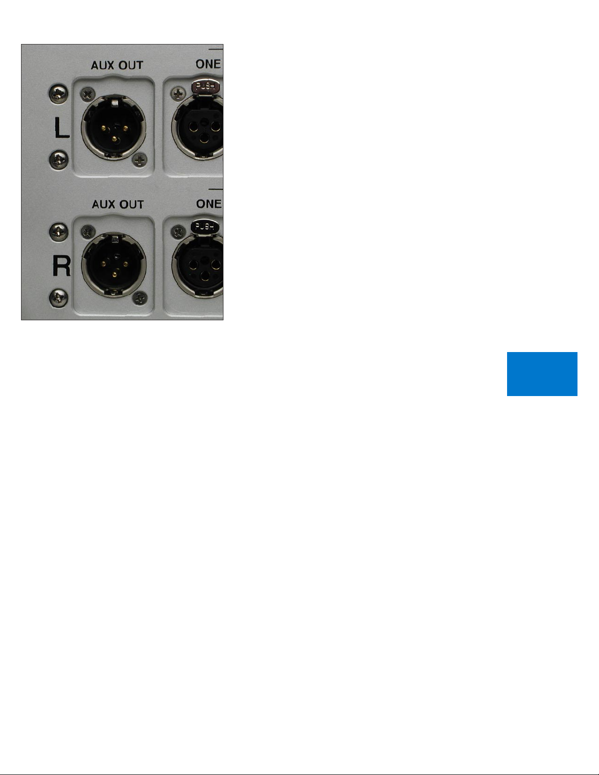
CONNECTING THE AUXILIARY OUTPUTS
The auxiliary output level of the 865 Integrated Amplifier can be set
to either a fixed mode suitable for use with a recording device or music
distribution system; or a variable mode for use with a subwoofer or
secondary amplifier. Instructions to program the outputs can be found
on page 4-6 of this manual.
WARNING: If the auxiliary outputs are used, selection of fixed or
variable mode must be programmed before connecting the outputs or
potential damage to your system may occur.
CONNECTING THE AUXILIARY OUTPUTS TO A
COMPONENT WITH BALANCED INPUTS
With your 865 Integrated Amplifier’s balanced outputs, cable
distances of more than 50 meters are practical.
When using these outputs for bi-amplification into balanced
inputs and if the external amplifier has the standard 26dB of gain, the
loudspeaker outputs of both the 865 and the external amplifier will be
equal.
1-6
GETTING
STARTED
Page 13
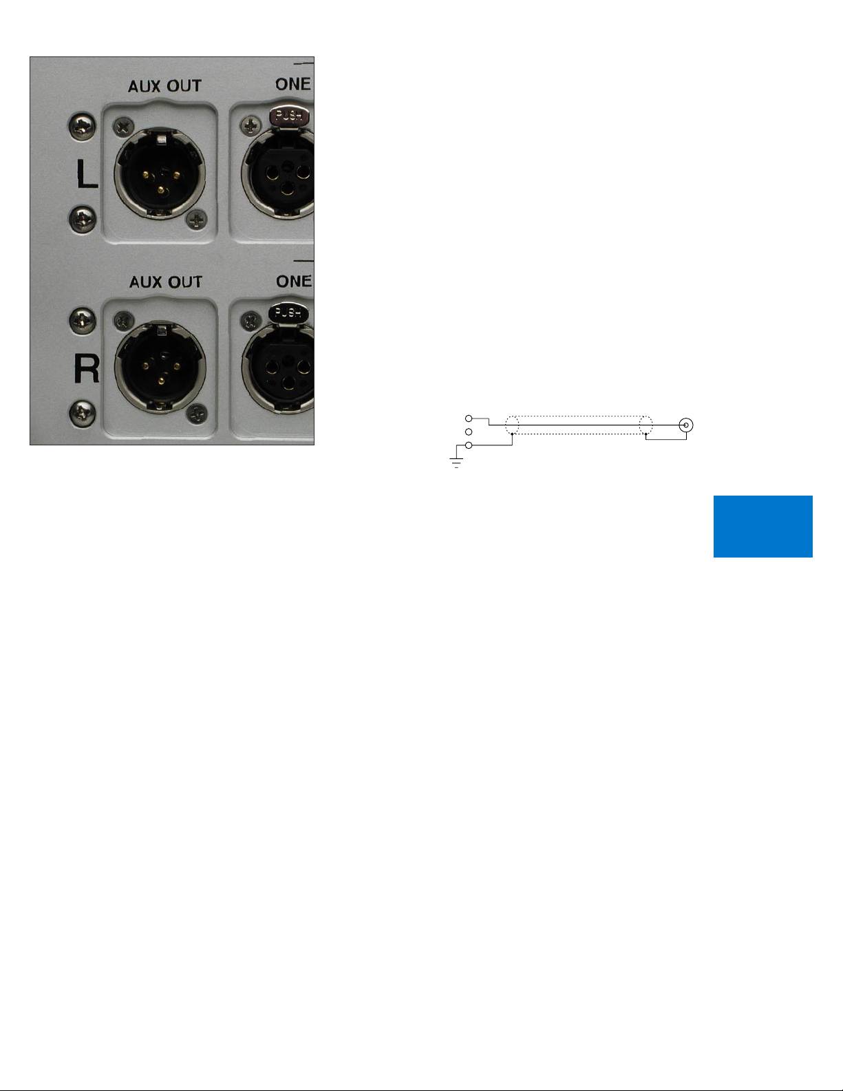
CONNECTING THE AUXILIARY OUTPUTS TO A
UNBALANCED OUTPUT CABLE
3-NEG OUTPUT
2-POS OUTPUT
1-GROUND
LINE
PREAMP
INPUT
COMPONENT WITH UNBALANCED INPUTS
The 865 Integrated Amplifier’s balanced outputs can drive
unbalanced inputs with a cable having an XLR connector at the source
(865) end and an RCA connector at the load end.
A special cable required to make this connection connects Pin 1
to the shield and Pin 2 to the RCA center conductor. It leaves Pin 3
unconnected.
Connecting the unused Pin 3 to ground will cause excessive ground
currents and degrade performance. Use an ohmmeter or continuity
checker to determine how a cable is wired. The diagram of the proper
termination technique for this cable is shown below.
When using these outputs for bi-amplification into unbalanced
inputs and if the external amplifier has the standard 26dB of gain, the
loudspeaker outputs of the 865 will be 6dB louder than the external
amplifier.
1-7
GETTING
STARTED
Page 14
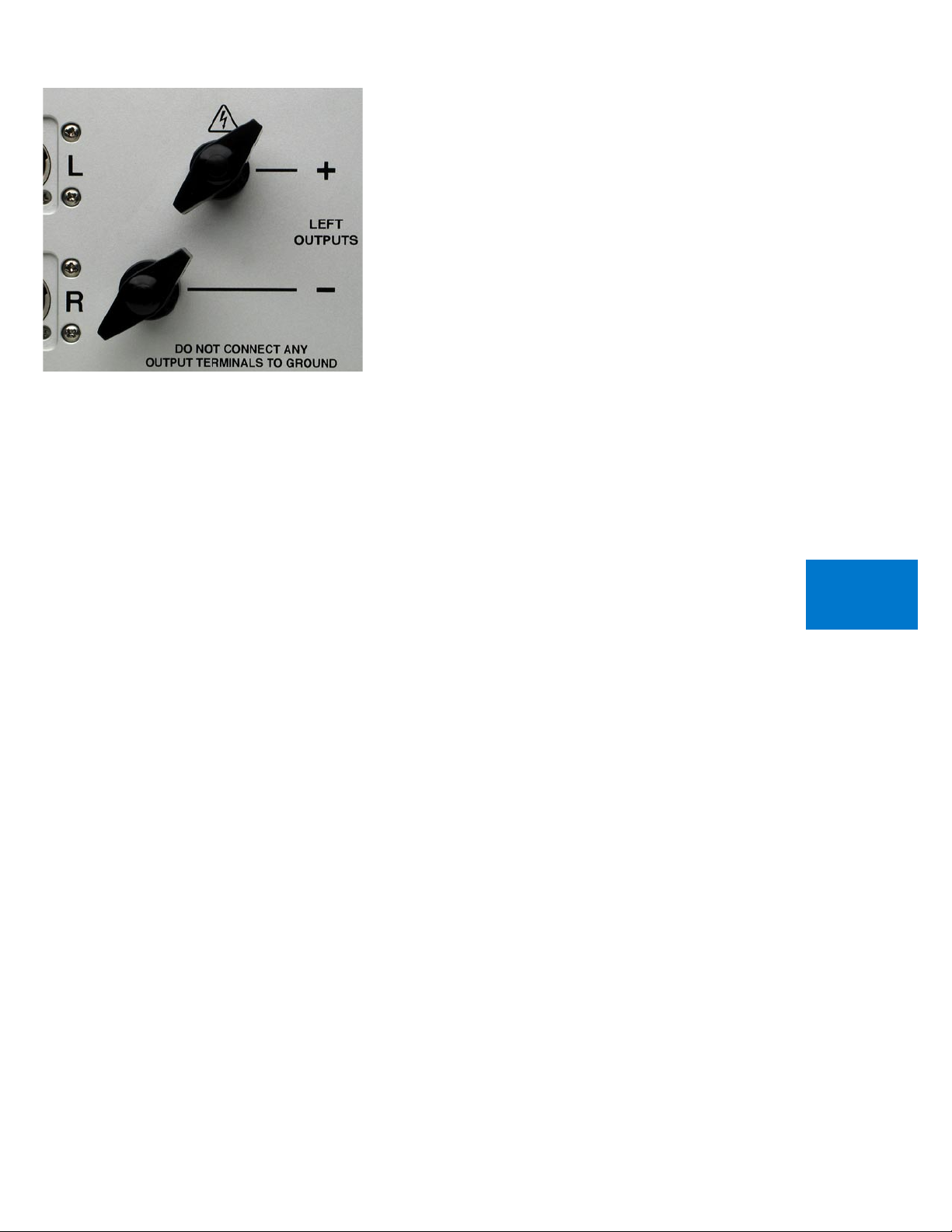
POLARITY
Please note that the 865 Integrated Amplifier conforms to the
standard of Pin 2 as the high or ”hot” for the balanced inputs.
The polarity of the 865 is such that a positive-going transition at
Pin 2 will produce a positive-going transition at the ”+” loudspeaker
terminal.
CONNECTING YOUR LOUDSPEAKERS
Do not use any wrenches on the loudspeaker binding posts. Tighten
these connectors only by hand.
WARNING: The 865 is a high powered amplifier. When driven, there
is a high voltage potential at the terminals.
Connections should only be made with the AC mains disconnected.
Select spade terminals which accept 6 mm or .250 inch diameter
binding posts.
There is no provision for the use of banana plugs. These plugs have
been proven to come loose over time which increases contact resistance
and distortion. For the same reasons we also do NOT recommend the
use of banana plugs at the loudspeaker end.
1-8
GETTING
STARTED
Page 15
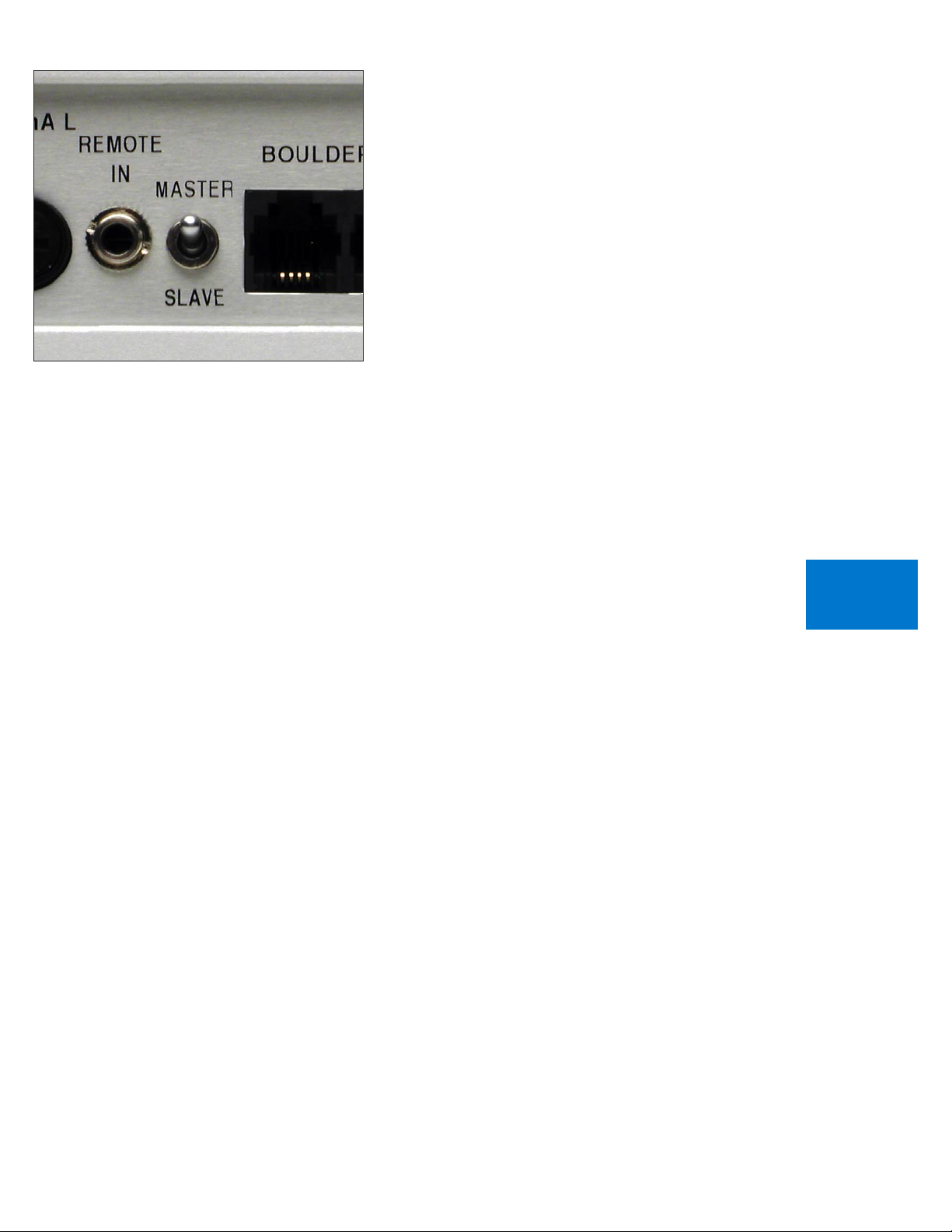
SETTING THE BOULDERLINK SWITCH
The normal setting of the MASTER / SLAVE switch is MASTER.
When using the 865 with only power amplifiers, the Boulderlink
MASTER / SLAVE switch should be set to MASTER.
For more information on Boulderlink, see the Boulderlink section 5-1
as indicated by the finger tab below.
1-9
GETTING
STARTED
Page 16
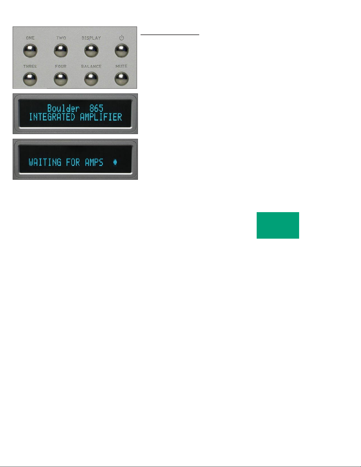
OP E RATI ON
POWERING UP
With all your connections made, you are ready to listen to your
Boulder 865 Integrated Amplifier.
The power LED will cycle through a variety of colors indicating a
standby mode. Power is applied only to the microprocessor while in this
mode.
Press the STANDBY button to turn on the 865. The indicator will
change to amber and power will be applied to the audio section.
During the power up sequence, the displays at left will be briefly
shown.
The front panel STANDBY button should be used for everyday turn
on and off. This switch mutes the audio, turns off all sections except the
microprocessor, and puts the 865 in standby mode.
2-1
OPERATION
Page 17
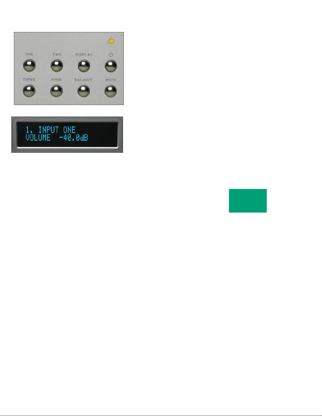
INPUT SELECTIONS
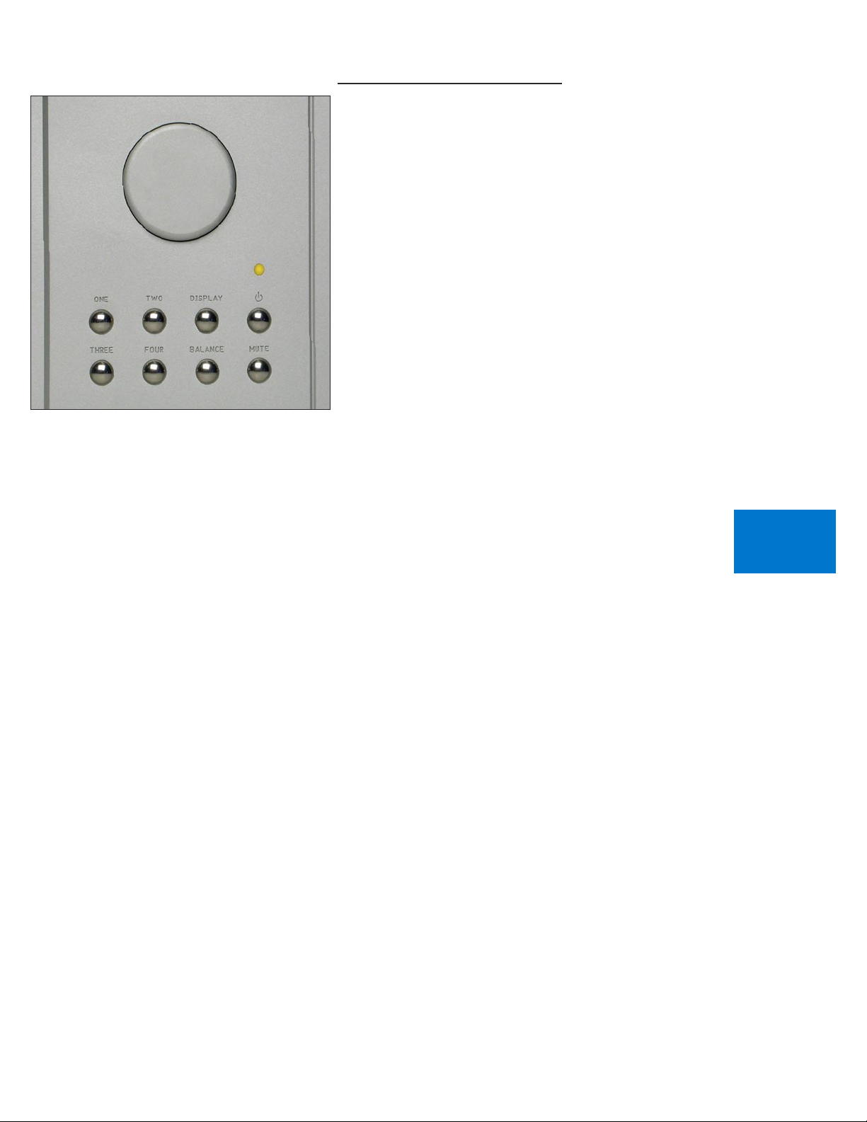
To select an input, press one of the pushbuttons labeled ONE, TWO,
THREE or FOUR. The respective input will be shown in the display and
that signal will be routed to both the loudspeaker and auxiliary outputs.
For example, if input ONE is chosen, “1. INPUT ONE” will show in the
display.
NOTE: There will be a delay when switching from one source to
another. This is necessary to allow the circuitry to adjust to the new
input source.
2-2
OPERATION
Page 18
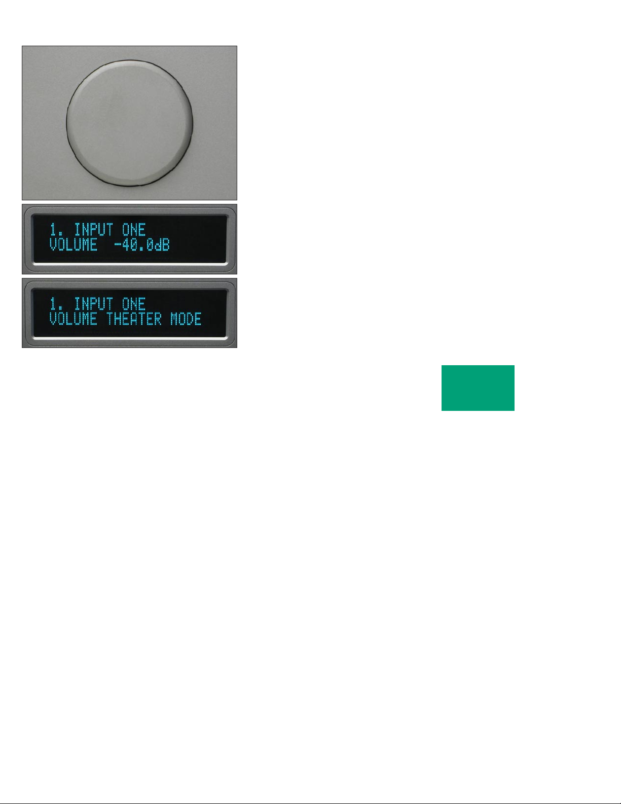
VOLUME
Because the precise feel of the Boulder 865’s volume control may be
different than you are used to, we recommend starting the source device
so that an audio signal is fed to the 865 before increasing the volume.
The display will show “VOLUME INFINITE” to indicate maximum
attenuation or no sound. By placing a finger at the edge of the rotating
control and moving it slowly so it turns in a clockwise direction, the
volume will increase and an indication such as “VOLUME - 40.0dB” in
the display will show the respective volume.
At this point you should be listening to music. Each volume step is
a change of 0.5 dB.
WARNING: The volume control must be given the respect you would
any other volume control with the ability to get loud very quickly.
WARNING: If the input is programmed to be in “THEATER
MODE,” then the volume control will have no effect. This mode is only
for use when there is a surround sound processor with a volume control
ahead of the 865.
For more information, see THEATER MODE in the programming
section on page 4-5.
2-3
OPERATION
Page 19
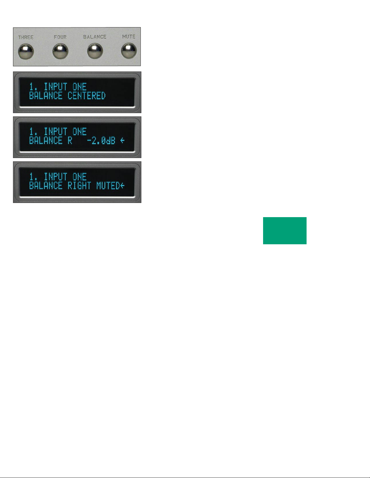
BALANCE
To change the level balance, press the BALANCE pushbutton.
“BALANCE CENTERED” will show in the display. Now, rotating the
control will change the balance instead of the volume for as long as
“BALANCE...” is displayed.
Turning the control counterclockwise (left) will cause an indication
such as “BALANCE R -2.0dB < “ in the display. This means that the right
channel has been attenuated -2.0 dB below the left channel, regardless of
volume setting, making the left channel louder.
The range of balance offset is limited to -20.0 dB. If the control is then
rotated further counterclockwise, the “BALANCE RIGHT MUTED<”
will be displayed to indicate that only the left channel is on.
2-4
OPERATION
Page 20
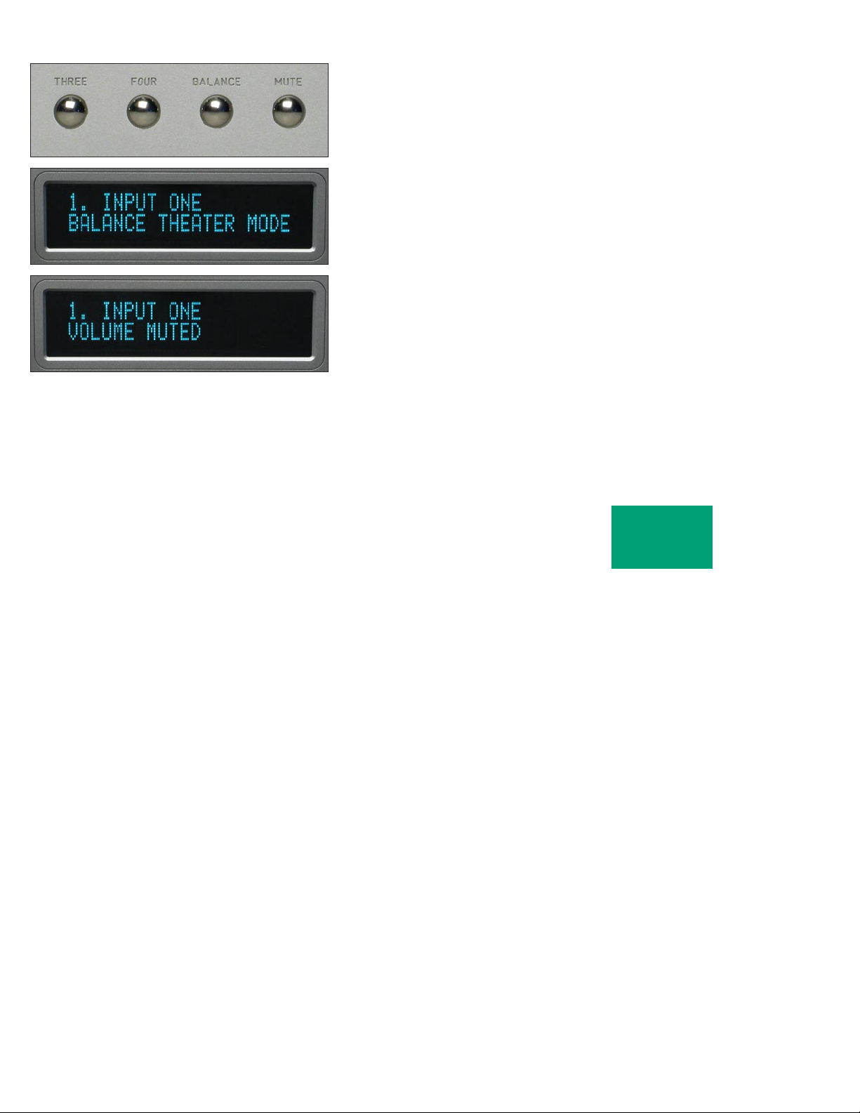
After several seconds of not changing the balance, the display
will return to the “VOLUME...” indication. You may also return to
controlling volume by again pressing the BALANCE pushbutton. The
balance resolution is the same as for the volume control, 0.5 dB steps.
WARNING: If the input is programmed to be in “THEATER MODE,”
then the balance control will have no effect.
For more information, see THEATER MODE in the programming
section on page 4-5.
MUTE
To temporarily reduce the volume, press the MUTE pushbutton.
“VOLUME MUTED” will show in the display, replacing the volume
indication. Again pressing the MUTE pushbutton will return the
volume to normal level.
While muted, the level of both channels will be set to -100 dB,
regardless of volume setting.
2-5
OPERATION
Page 21
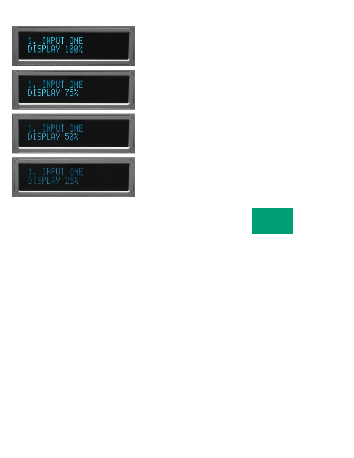
DISPLAY
The display brightness may be set to any of four brightness levels. To
change the brightness level, press the DISPLAY pushbutton. “DISPLAY
100%” will show in the display. Rotate the center control until the
desired brightness is obtained such as “DISPLAY 50%.” The number in
the display is the relative brightness.
After several seconds of not changing the brightness level, the
display will return to the “VOLUME...” indication. You may also return
to controlling volume by again pressing the DISPLAY pushbutton.
With the display at a brightness less than that of 100%, any operation
of a pushbutton or the volume control will cause the display to go to
full brightness for several seconds, and then return to the programmed
brightness. This ensures that if a function is changed, it will be noticed
whether intentional or inadvertent.
2-6
OPERATION
Page 22
RE M OT E CO N TRO L
BATTERIES
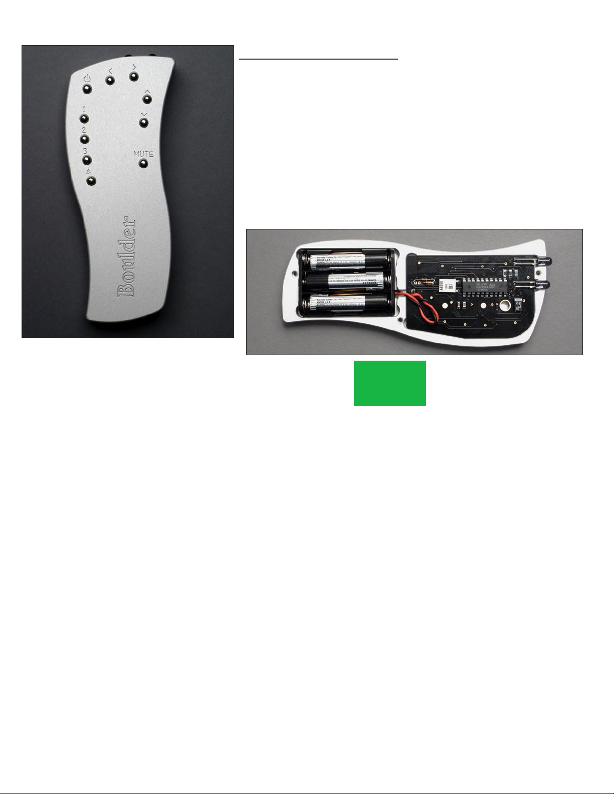
A standard small flat-blade screwdriver is required to install the three
AAA batteries. To install batteries in the remote control, it is necessary to
separate the two sections.
WARNING: When opened, the pushbutton balls will be loose and
care must be taken to properly retain them.
It is recommended to lay the remote control face down on a flat
surface so that the balls will stay in position. Then, remove the three
screws. Lift off the cover and set aside, making certain that the battery
holder comes out from the cover. Install the batteries with the positive
(+) terminals facing as indicated on the holder and replace the cover.
3-1
REMOTE
CONTROL
Page 23
SOURCE SELECTION
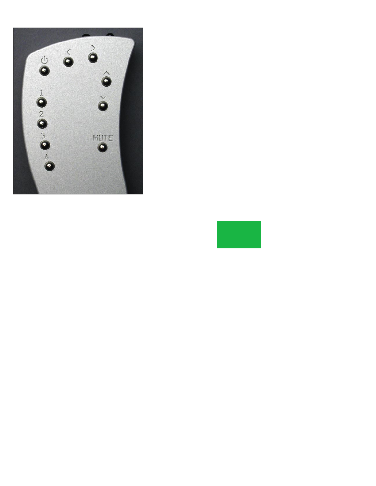
To select an input (source) press the button on the left side of the
remote control whose number corresponds to the input you wish to
listen to, and it will show in the display. You will now be listening to
your desired input.
VOLUME, BALANCE and MUTE
To increase the volume, press the button on the right side marked
with an up arrow. To reduce, press the button marked with a down
arrow. Holding either button down will cause the volume to change
continuously until released.
To change the balance to the left, press the button at the top marked
with a left arrow until the display shows “BALANCE CENTERED” and
continue holding until the display shows the desired balance change.
Similarly, you may change the balance to the right by holding the button
marked with a right arrow.
To temporarily mute the audio, press MUTE. To return to normal
audio level, again press MUTE.
3-2
REMOTE
CONTROL
Page 24
PR O GR A MMI N G
While it is not necessary to ever use any programming functions, you
will find they maximize the enjoyment of your Boulder 865 Integrated
Amplifier.
Each input has several programmable features associated with it.
These include assigning an alphanumeric name of your choosing, setting
an individual start volume and balance, and setting Theater Mode.
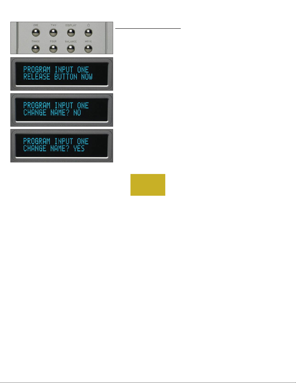
After holding down the desired input button until “RELEASE
BUTTON NOW” is displayed, each additional press of this input button
will step through the programming options. Changes made during the
programming process are automatically stored as they are made. If no
changes are made, the original settings are retained.
INPUT NAMES
For each input, press and hold the input number you wish to
program. If you selected ONE, then “PROGRAM INPUT 1” will show
in the top display row and “CHANGE NAME? NO” will show in the
bottom display row. Rotating the volume control clockwise will allow
you to choose “YES” if you want to change the name. Press the same
input source number again to continue.
4-1
PROGRAMMING
Page 25

If you chose to assign a name, then “1 INPUT ONE” will be shown
in the bottom display row with a blinking cursor before the name’s first
character. Rotate the control until the desired character appears. Press
the same input source number to accept the displayed character and go
to the next character. Continue in this manner until all 17 characters are
set. For example, “Boulder” can be set.
NOTE: The space character is just before the exclamation mark
(”!”).
4-2
PROGRAMMING
Page 26
INPUT LEVEL CALIBRATION
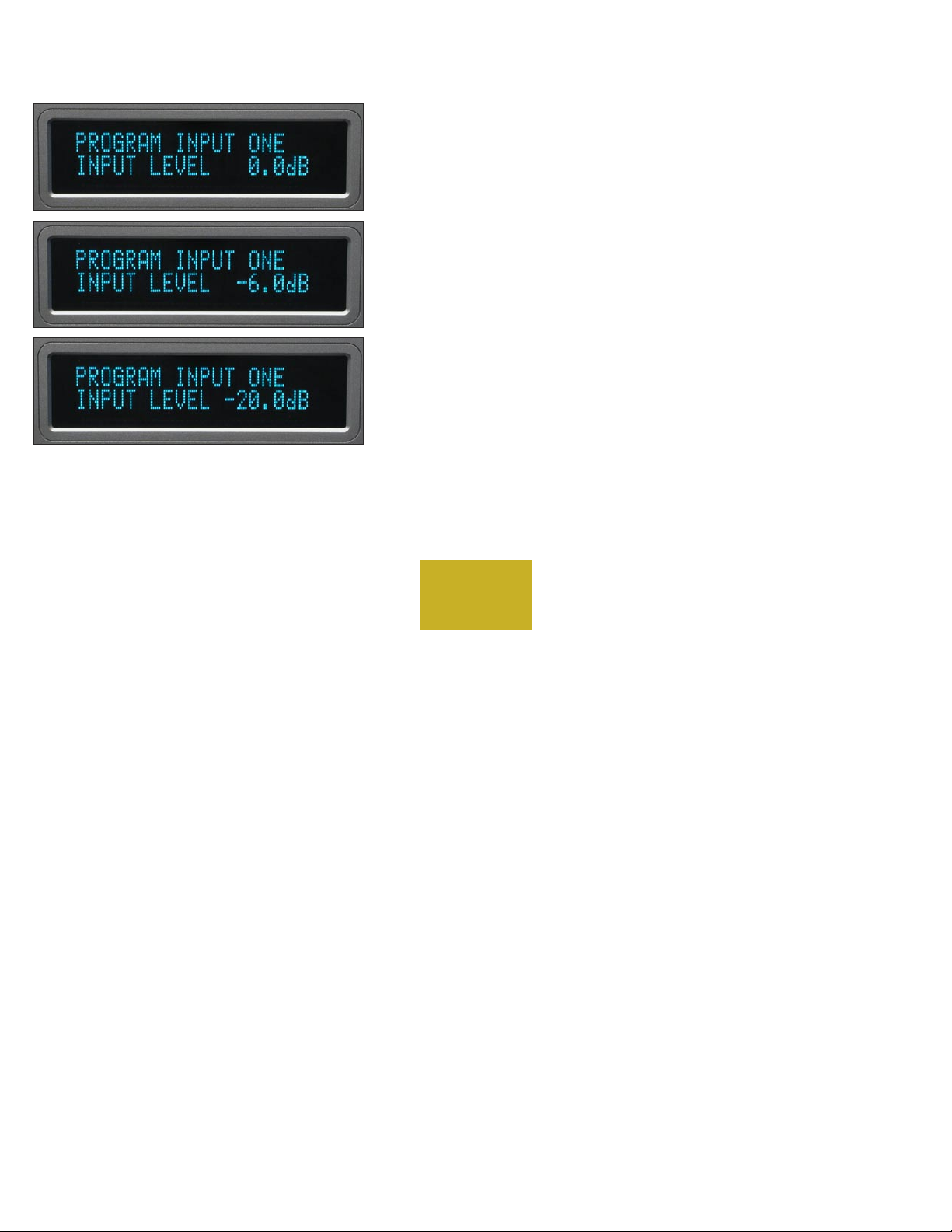
Pressing the same input source number will make “INPUT LEVEL
0.0dB” show in the bottom display row. Rotating the volume control
will change the display and the loudspeaker levels simultaneously. This
allows calibration of each input with test tones if desired.
For example, setting the display to “-6.0dB” will allow an input
which is twice the voltage of the other inputs to be heard at the same
level. A maximum of -20 dB may be set.
This is easiest to do if you start with the quietest source as your
reference, and then adjust the louder sources to match it.
4-3
PROGRAMMING
Page 27
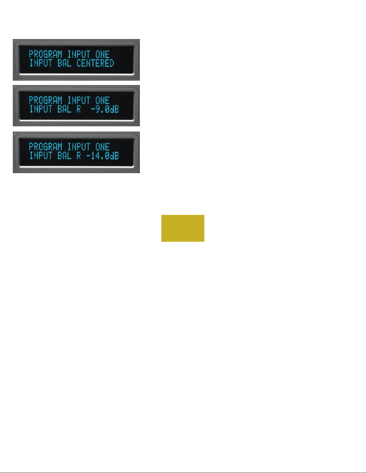
INPUT BALANCE CALIBRATION
Pressing the same input source number will make “INPUT BAL
CENTERED” show in the bottom display row. Rotating the volume
control will simultaneously change the display and the loudspeaker
balance so that the action can be monitored or measured.
For example, setting the display to “R -9.0dB” will make the left
channel louder than the right channel. A maximum of -14 dB may be
set.
Pressing the same input source number again will end the
programming of this input and initiate a power up sequence.
4-4
PROGRAMMING
Page 28
THEATER MODE
When the 865 Integrated Amplifier is used in a surround sound or
home theater system, it is normally desired to bypass the volume control,
thus letting the surround processor control the volume.
WARNING: Setting an input to THEATER MODE forces the volume
to unity gain. Use only in conjunction with a surround processor.
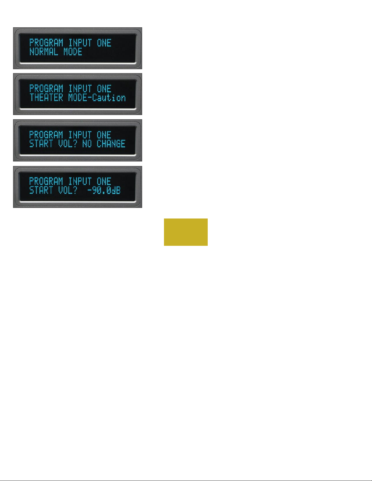
Pressing the same input source number again will make “NORMAL
MODE” show in the bottom display row. Rotating the volume control
will show “THEATER MODE-Caution.”
START VOLUME
When selecting an input, it is possible to have the 865 go to a preset
volume level every time that input is selected.
Pressing the same input source number will make “START VOL?
NO CHANGE” show in the bottom display row. Rotating the volume
control will allow you to choose -50, -60, -70, -80, or -90 dB as the new
preset level.
4-5
PROGRAMMING
Page 29
PROGRAMMING BY THE DISPLAY BUTTON
Several special features are programmed by pressing and holding
the DISPLAY pushbutton until the display changes, indicating you are in
a programming mode. If no action is taken for some time, then the 865
reverts back to normal operation. The sequence is as follows.
AUXILIARY OUTPUTS MODE
A separate pair of balanced outputs are provided for connection to
other components. These outputs can be programmed for either fixed
output for connection to recording or audio distribution systems, or
variable output operation for connection to an external amplifier or
subwoofer.
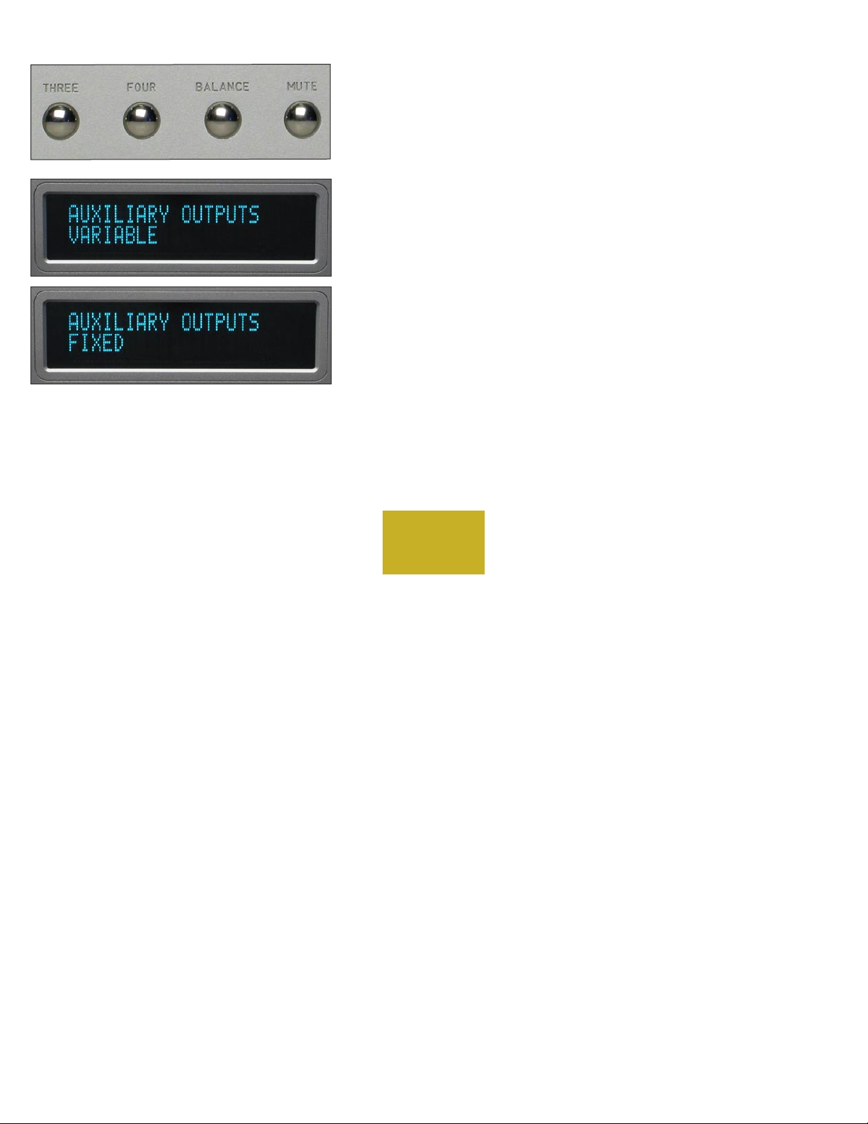
”VARIABLE” will show in the bottom display row. Rotating the
volume control will show ”FIXED.”
4-6
PROGRAMMING
Page 30
BOULDERLINK ID
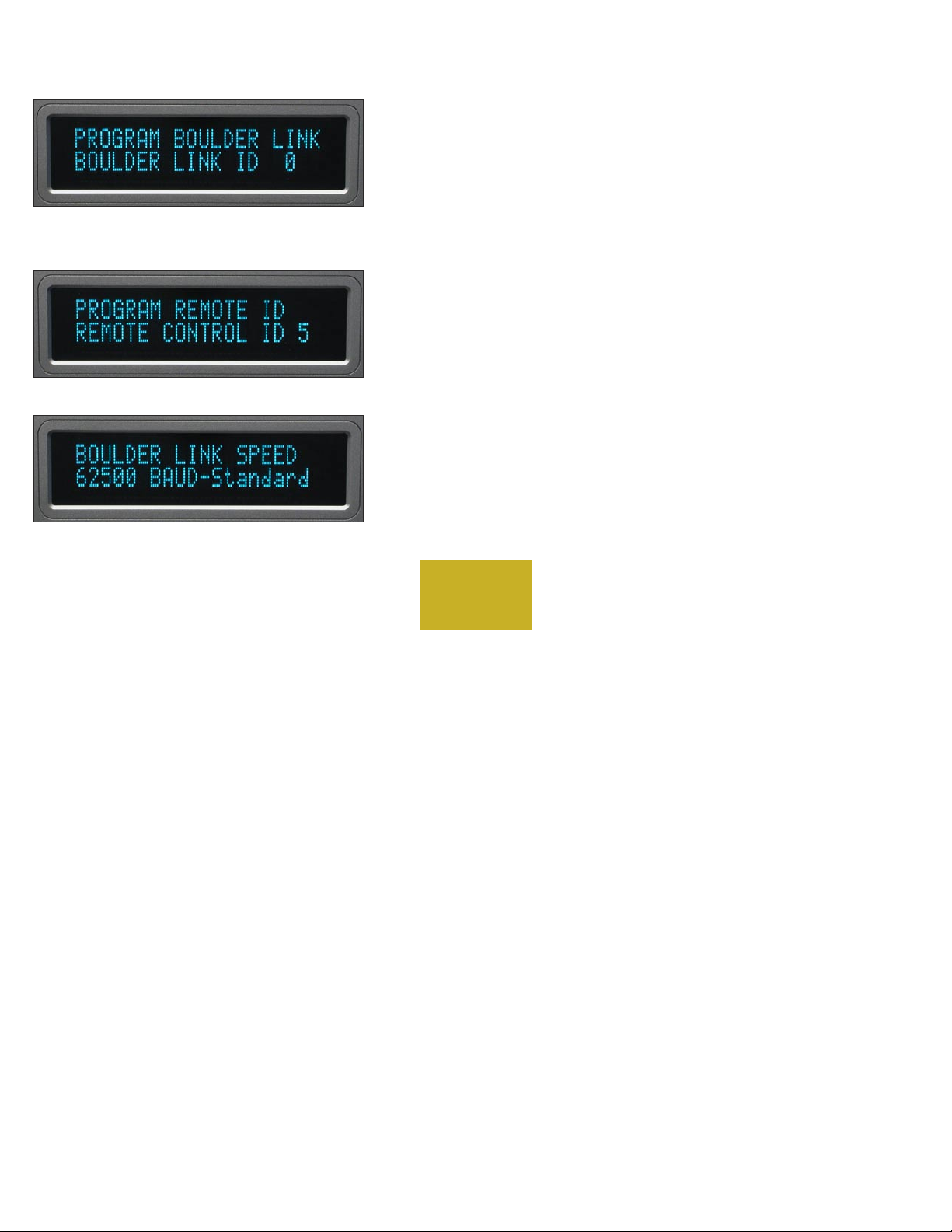
Pressing the DISPLAY pushbutton again will make “PROGRAM
BOULDER LINK, BOULDER LINK ID 0” show in the display. Rotating
the volume control changes the ID number. For more information
consult the Boulderlink section.
Unless you are using two or more 865 Integrated Amplifiers together,
this setting should be left at “0.”
REMOTE ID
Pressing the DISPLAY pushbutton again will make “PROGRAM
REMOTE ID, REMOTE CONTROL ID 5” show in the display. Rotating
the volume control changes the ID number. This feature is used in
conjunction with a wiring change in the remote control and should
always be left set at “5.” Consult your dealer to change this setting.
BOULDERLINK SPEED
Pressing the DISPLAY pushbutton again will make ”BOULDERLINK
SPEED, 62500 BAUD-Standard” show in the display. Rotating the
volume control changes the baud rate. This feature increases the 1012’s
compatibility with other brands of equipment. Consult your dealer
before changing this setting.
4-7
PROGRAMMING
Page 31
RESET TO FACTORY DEFAULTS
Should you wish to have all settings reset to original factory defaults,
you may execute a master reset. Normally, this function is not used.
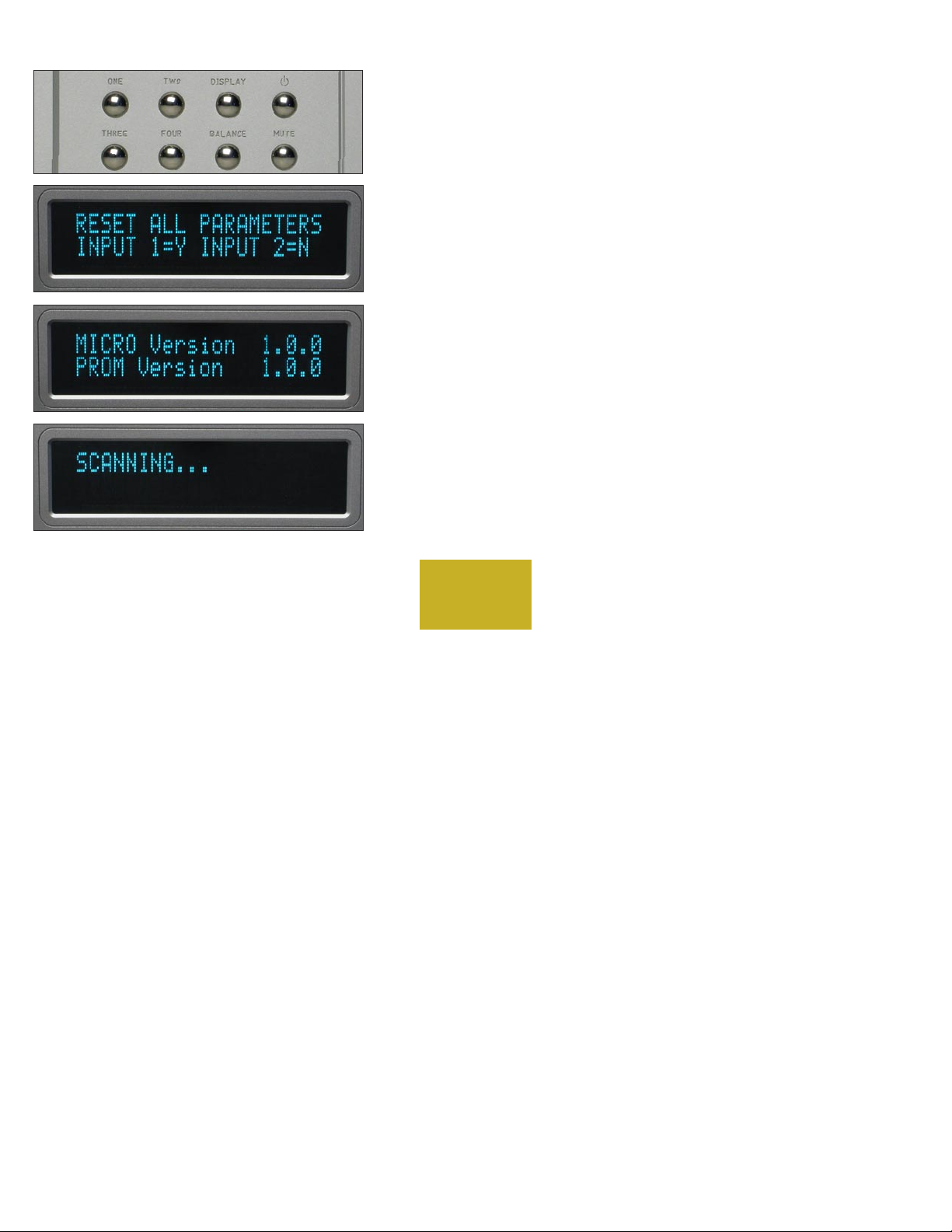
Press and hold the STANDBY pushbutton. “RESET ALL
PARAMETERS, INPUT 1=Y, INPUT 2=N” will show in the display.
To leave all settings as they currently are, press the TWO
pushbutton.
To reset all settings to factory defaults, press the ONE pushbutton.
WARNING: ALL personalized program settings will be lost,
including the names of each input.
The microprocessor and PROM version numbers will momentarily
be displayed, followed by ”SCANNING…”
All other pushbuttons are inoperative during this time. The 865
Integrated Amplifier will then return to normal operating mode and
initiate a power up sequence.
4-8
PROGRAMMING
Page 32
BO U LD E RLI N K
BOULDERLINK "DAISY CHAIN"
TO ALL
OTHER
SLAVE
UNITS
BOULDER
PRE-
AMPLIFIER
BOULDER
POWER
AMPLIFIER
BOULDER
POWER
AMPLIFIER
MASTER SLAVE SLAVE
Boulderlink is a means of interconnecting most Boulder products
so that their microprocessors can talk to each other and pass important
information. Among the key features, Boulderlink allows sequential
initiation of power amplifiers and other products when the 865
Integrated Amplifier is turned on. Power amplifiers can send messages
to the 865 which are then shown on its display.
CONNECTING BOULDERLINK
Turn off all products that are to be linked before connecting any
Boulderlink cables and setting Boulderlink ID and Master/Slave
switches.
Boulderlink cables in various lengths are available as an accessory
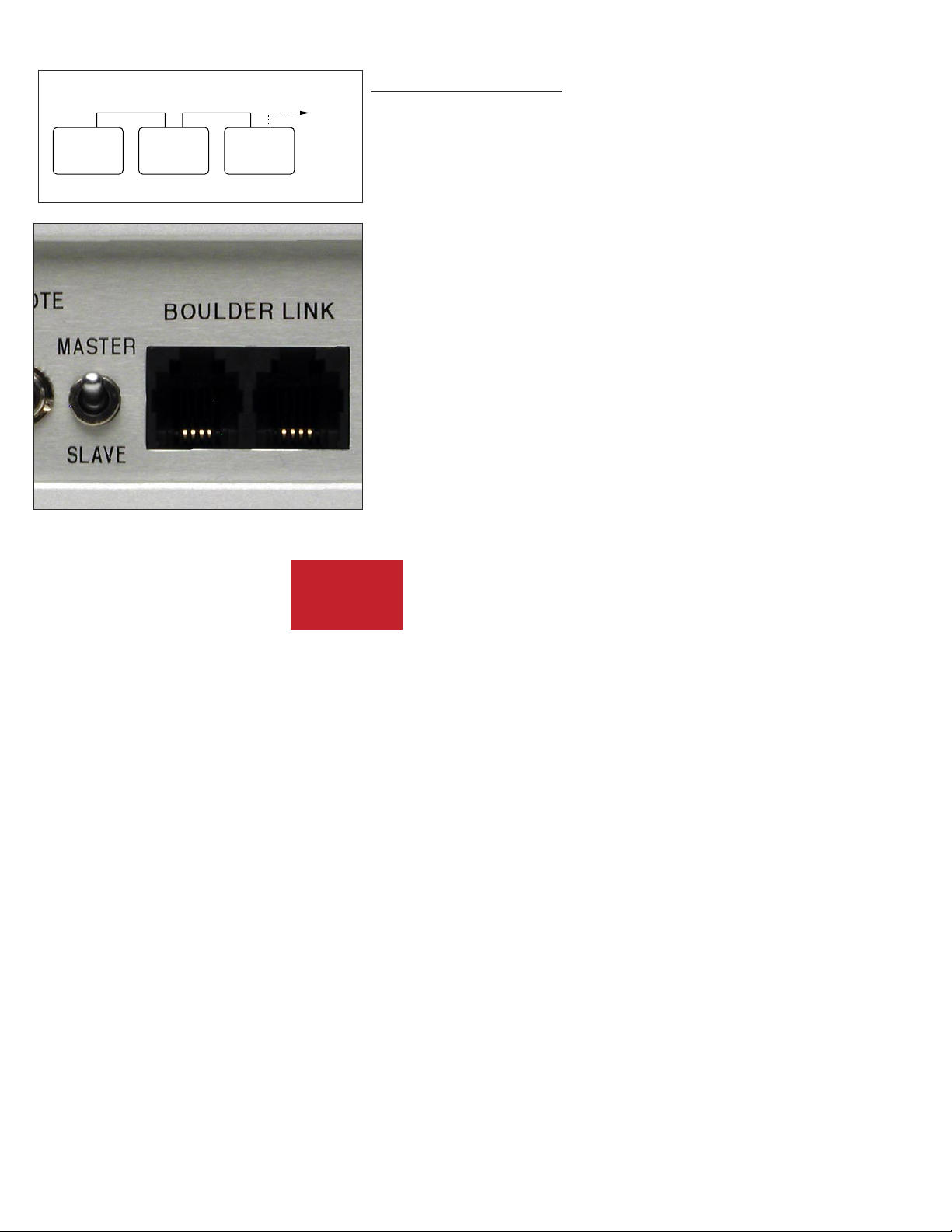
from your Boulder dealer. Two connectors are provided on the back of
the 865 and other Boulderlink enabled products.
All the chassis are connected together in a daisy chain manner. Start
by connecting one chassis to another—then from that chassis to the next
until all are connected. The order does not matter.
A special interface may be obtained to enable Boulderlink to be used
with other control systems. Contact your Boulder dealer for details.
5-1
BOULDER
LINK
Page 33
CONNECTING 800 SERIES TO 1000 OR 2000 SERIES WITH
BOULDERLINK
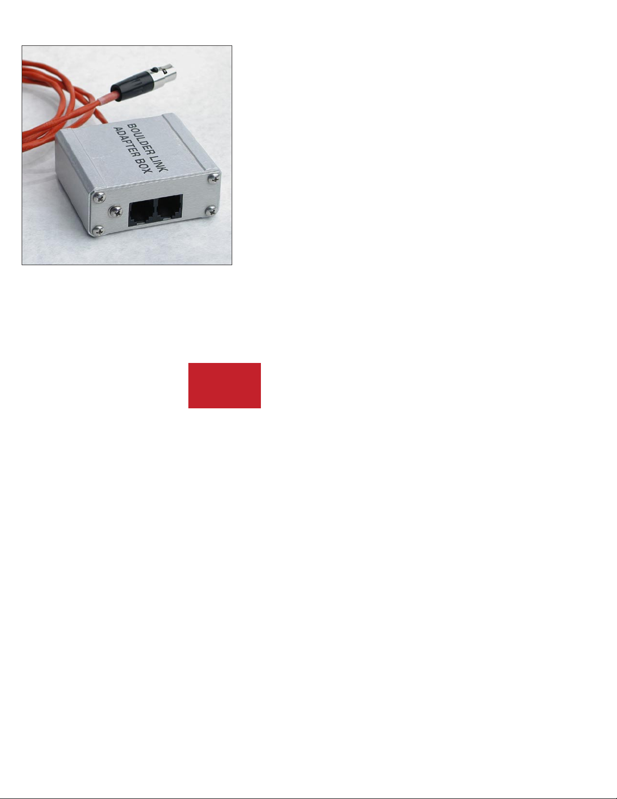
If you are using the 865 Integrated Amplifier with certain other
Boulder products, a Boulder Link Adapter Box (BLAB) might be required
to make the connection.
Although the connectors are mechanically different between the
series, they are electrically the same, thus allowing the various series to
be mixed.
Contact your Boulder dealer for further information.
5-2
BOULDER
LINK
Page 34
SETTING BOULDERLINK SWITCHES
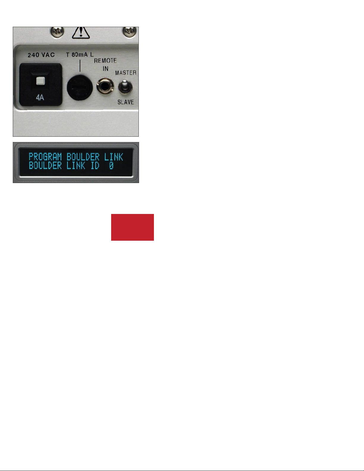
Every Boulderlink system must have one “MASTER” component,
and only one component can be set to MASTER. Usually this is the
preamplifier or CD Player. Power amplifiers and other products not
having a MASTER/SLAVE switch can never be “MASTER.”
On the 865, the Boulderlink MASTER/SLAVE switch will normally
be set to MASTER.
SETTING BOULDERLINK ID NUMBERS
Each component is required to have a unique Boulderlink ID
number. The 865 ID is preset to 0 at the factory and/or when a master
reset sequence is executed.
Each Boulder power amplifier has a thumbwheel switch on the rear
panel. Start by setting the first switch to 0 or 1 and then going up from
there without any duplication. Use of the lowest numbers will speed
up turn on as each amplifier is allowed about 3 seconds before the next.
This spreads out the power line inrush currents thus preventing house
circuit breakers from unnecessary tripping. In addition to the 865, up to
15 power amplifiers may be connected together in one Boulderlink cable
daisy chain.
5-3
BOULDER
LINK
Page 35
POWER UP VIA BOULDERLINK
With each component connected together with a Boulderlink cable,
and individually connected to the AC mains, pressing the 865’s STANDBY
pushbutton will initiate the turn-on sequence of all components.
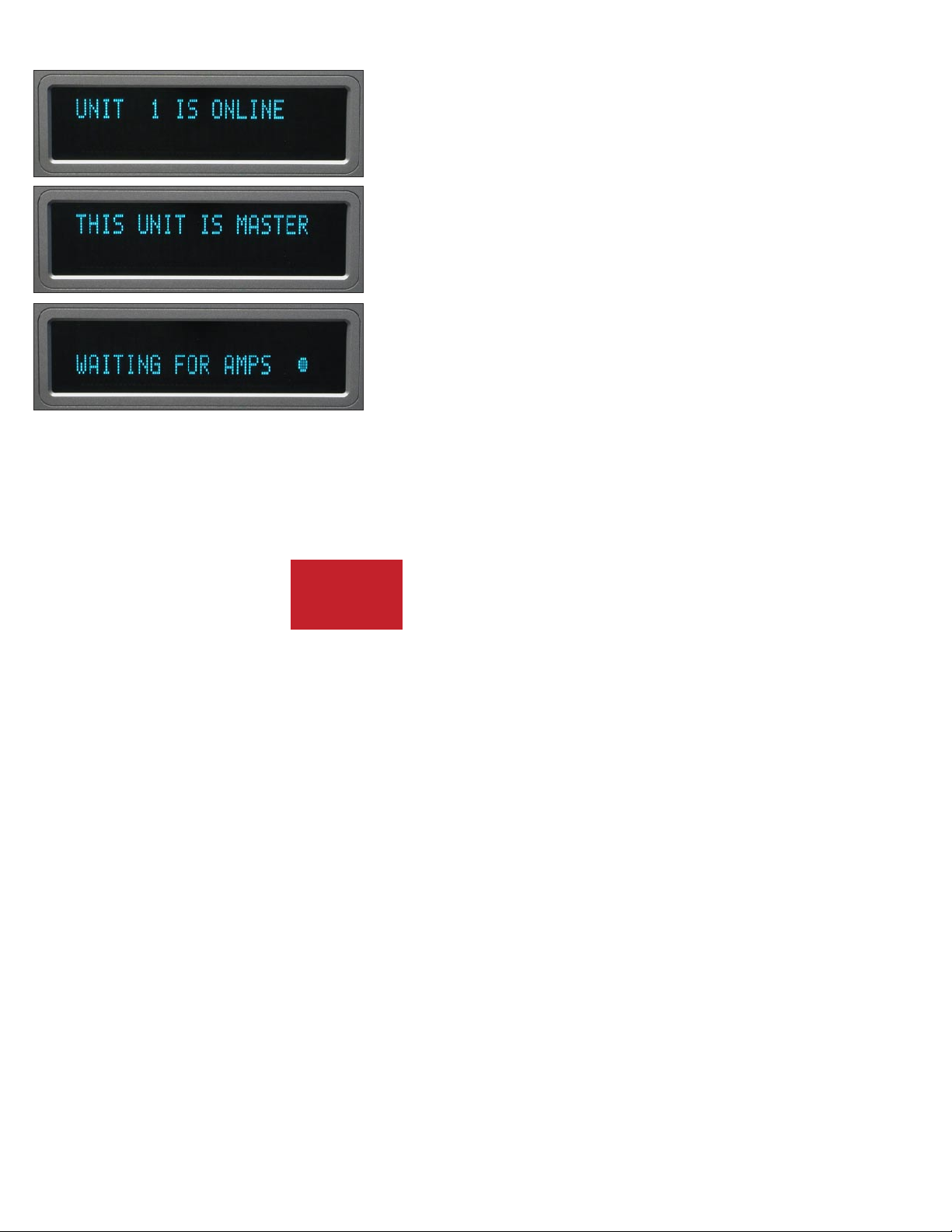
The first time a “MASTER” 865 is powered up, it will search for any
“slave” units connected to it. As the Master finds each slave, the slave’s
ID number will be shown on the display.
If any of the connected slaves are amplifiers, then each time the
master is turned on it will display “WAITING FOR AMPS.” Each
amplifier will be turned on in the order of their Boulderlink ID. To
minimize turn on time, the amplifier’s Boulderlink IDs should be set to
the lowest sequential numbers possible other than 0. For example, use 1,
2, and 3 instead of 13, 14, and 15. An amplifier set to ID 15 will take 47
seconds to turn on.
5-4
BOULDER
LINK
Page 36

An 865 set to “SLAVE,” will display “THIS UNIT SLAVE #______.”
If there is no component set to “MASTER,” the 865 will display
“THERE IS NO MASTER!” In this case, the 865’s MASTER/SLAVE
switch should be set to MASTER. It may take up to 30 seconds for the
865 to recognize the switch change.
5-5
BOULDER
LINK
Page 37
BOULDERLINK MESSAGES
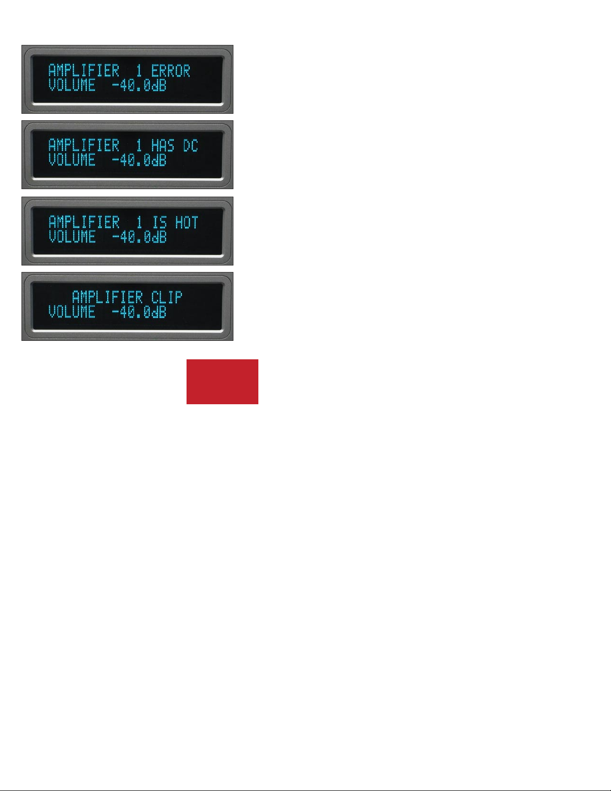
Each component in the system can send a message to the 865 which
is then shown on its display. This is particularly helpful in confirming
the operating status of each power amplifier in a multiple amplifier
system.
“AMPLIFIER 1 ERROR” means that an internal power supply has
failed and the amplifier has turned itself off to protect the speakers from
damage.
“AMPLIFIER 1 HAS DC” means that it has turned itself off due to a
DC offset voltage being detected at its inputs.
“AMPLIFIER 1 IS HOT” means that is has turned itself off due to a
higher than normal temperature condition on the heatsinks.
“AMPLIFIER CLIP” means that the amplifier’s output has
momentarily reached its output voltage limitation.
5-6
BOULDER
LINK
Page 38

“UNIT 1 IS OFFLINE” means that the slave is no longer responding
via Boulderlink. Its Boulderlink cable may have become disconnected,
or the AC mains power has been disconnected.
“UNIT 1 IS ONLINE” means that the slave is now responding
via Boulderlink in a normal manner and has been recognized by the
master.
5-7
BOULDER
LINK
Page 39
RE C OR D ING
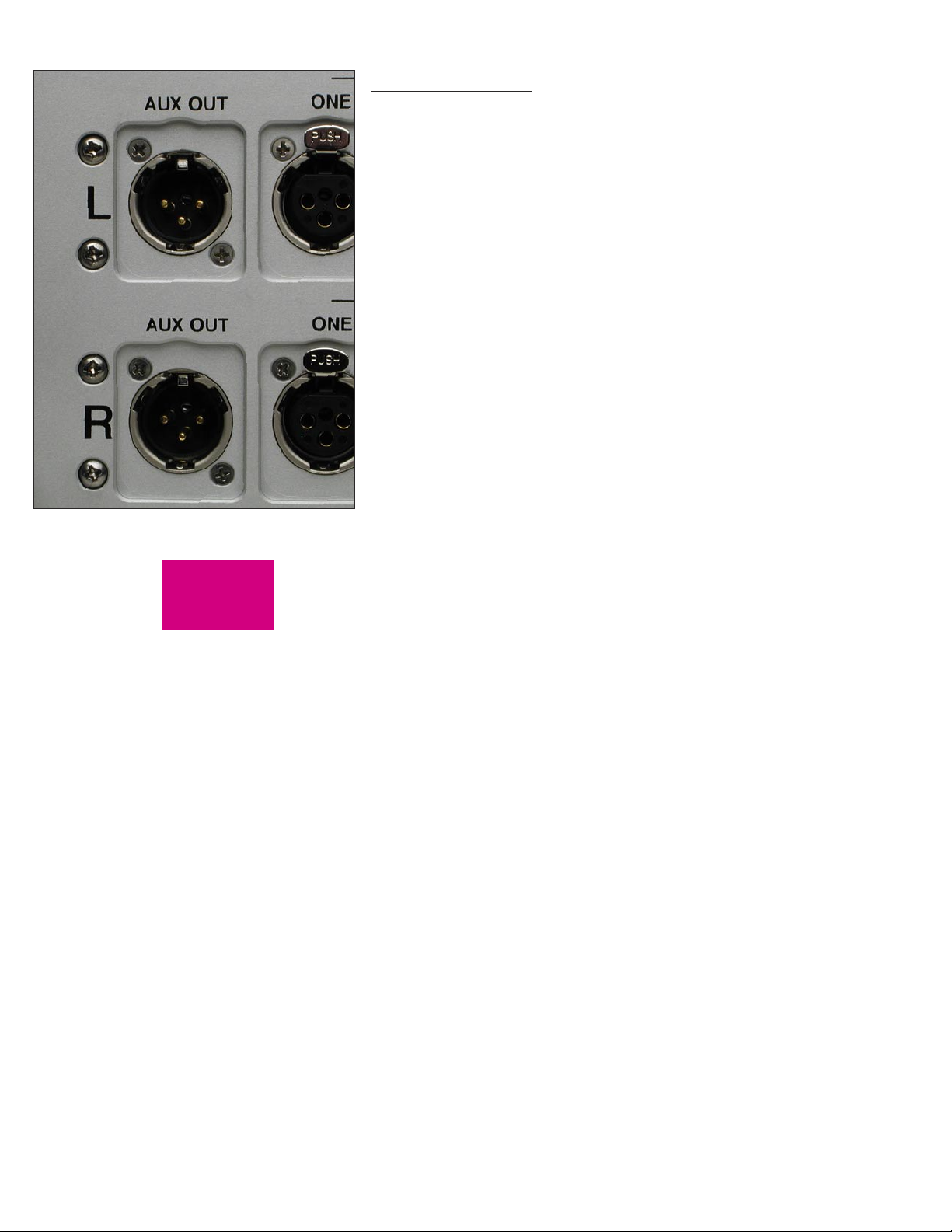
The Auxiliary outputs may be used for making recordings or
supplying a fixed level output to other system components.
CONNECTING A RECORDING DEVICE
A recording device may be connected to the 865 Integrated Amplifier.
You may use balanced or unbalanced connections as previously described
in the sections on connecting Auxiliary outputs. See pages 1-6 and 1-7.
The Auxiliary outputs should be programmed for fixed output mode
when making recordings. See page 4-6.
6-1
RECORDING
Page 40
7-1
APPENDIX
Page 41

BO U LD E R 8 6 5 I N TEG R AT ED A MPL I FIE R S P ECI F ICATI ON S
Balanced Line Inputs 4 pair
Auxiliary Balanced Outputs 1 pair (Switchable, Fixed or Variable)
Loudspeaker Output Connectors 6 mm/.250 inch post
Continuous Power, 8, 4 Ohms 150W
Peak Power, 4 Ohms 300W into 4 Ohms
THD at Continuous Power 20 to 2 kHz: 0.0035%. 20 kHz: 0.018%
Signal to Noise Ratio (re: 150W/8 Ohms) -108 dB, unweighted, 20 to 22 kHz
Frequency Response, 20 to 20 kHz +0.00, -0.07 dB
Frequency Response, -3 dB 0.015 Hz, 95 kHz
Maximum Input Level 6.0 Vrms
Input Impedance 100kΩ Balanced, 50kΩ Unbalanced
Common Mode Rejection (Balanced only) 60Hz: 90dB, 10kHz: 70dB
Crosstalk, L to R or R to L -112 dB or better, 20 Hz to 20 kHz
Crosstalk, Adjacent Inputs -112 dB or better, 20 Hz to 20 kHz
Volume Control Range 100 dB
Volume Steps 200 steps at 0.5 dB, ±0.05 dB
Maximum Voltage Gain 46 dB
Gain at Auxiliary Output Balanced: +4 dB, Unbalanced: -2 dB
Amplifier Size, W x H x D 17.0 x 7.38 x 15.25 inches, speaker connectors add 1.50” to depth
Weight 47 pounds. Shipping: 54 pounds
Power Requirements Voltage suitable for country where sold, 50-60 Hz
850W Maximum, 3W Standby
All specifications taken at 120 VAC mains power
7-2
APPENDIX
Page 42

TROUBLESHOOTING
SYMPTOM CAUSE REMEDY
No power indication Amplifier is not plugged in Connect to AC mains outlet
AC mains power switch in OFF position Turn rear panel switch ON
Fuse open or missing Reinsert or replace fuse
Red power indication Low line voltage Have line voltage checked
Power supply breaker open Reset breaker on rear panel
Amplifier is defective Return to dealer for service
Analog source selected, amber power
indication but sound not heard from either
channel
Amber power indication, but sound not
heard from one channel
No signal from source Check source controls, cables and
connections
No signal to loudspeakers Check loudspeaker cables and
connections
Output muted Press MUTE button
Amplifier is defective Return to dealer for service
No signal from one channel of source Check source controls, cables and
connections
One channel is muted by balance control Press BALANCE and recenter
Amplifier is defective Return to dealer for service
7-3
APPENDIX
Page 43

NOTES
7-4
APPENDIX
 Loading...