

Page 1
Page 2

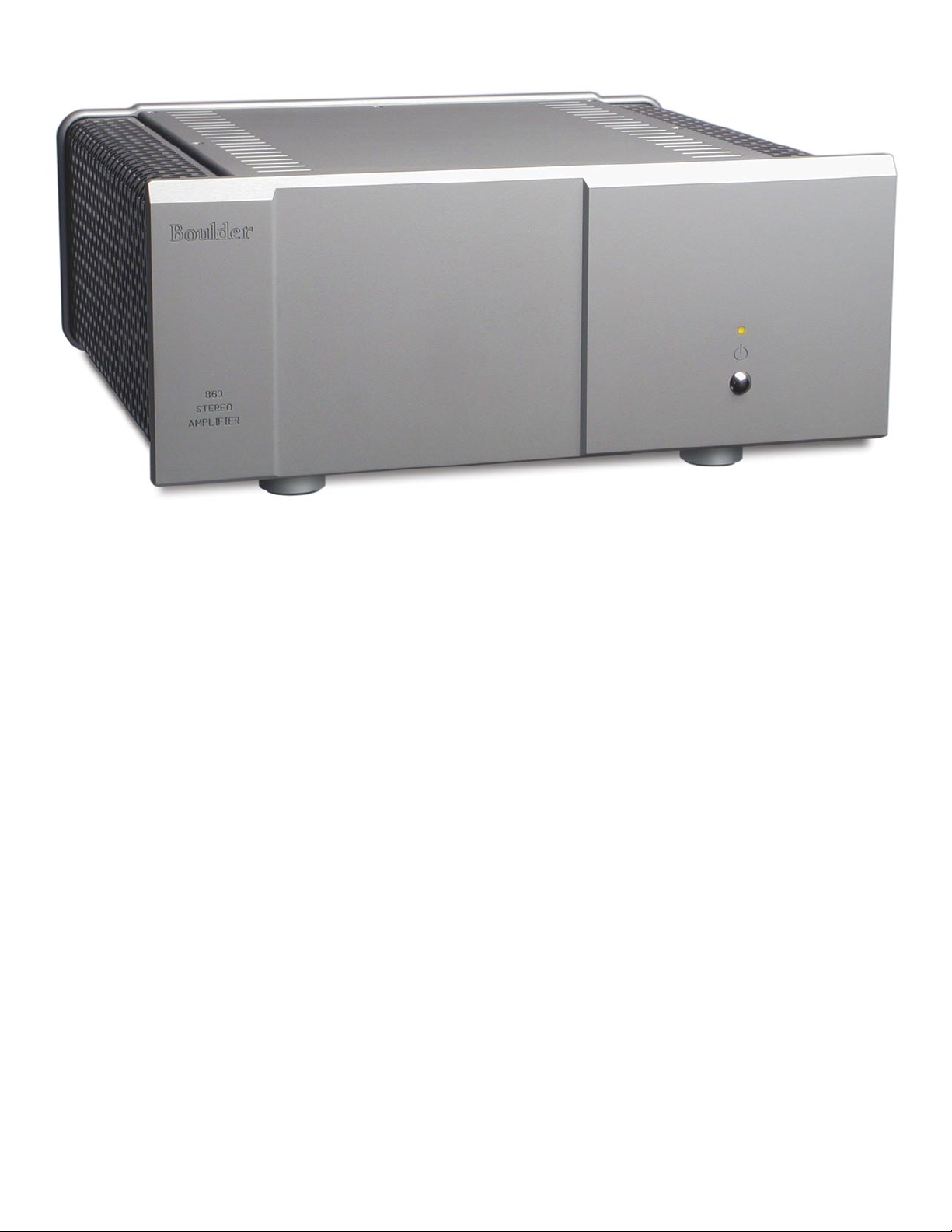
Boulder 860
150 Watt
Stereo Power Amplifier
Instruction Manual
6/13/07
Boulder Amplifiers, Inc.
3235 Prairie Ave.
Boulder, CO 80301
www.boulderamp.com
APPENDIX
BOULDER
LINK
REMOTE
CONTROL OPERATION
GETTING
STARTED
Page 3
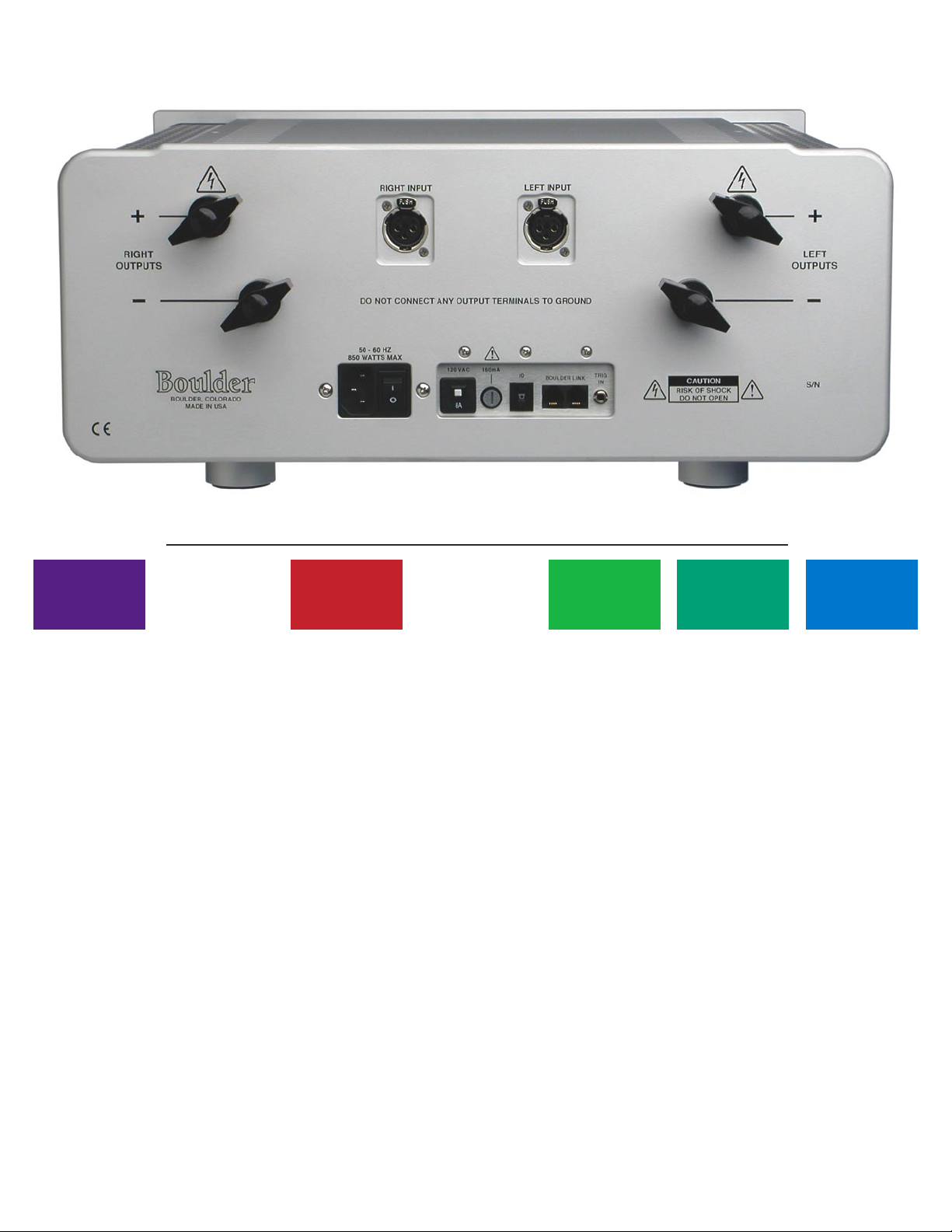
B o u l d e r 8 6 0 S t e r e o P o w e r A m p l i f i e r R e a r P a n e l
APPENDIX
BOULDER
LINK
REMOTE
CONTROL OPERATION
GETTING
STARTED
Page 4

GETTING STARTED
Placement of the 860 Stereo Power Amplifier. . . . . . . . . . . . . . . . . . . . . . . . . . . . . . . . . . . 1-1
Connecting to the Mains Outlet . . . . . . . . . . . . . . . . . . . . . . . . . . . . . . . . . . . . . . . . . . . . . . 1-2
Connecting a Balanced Source. . . . . . . . . . . . . . . . . . . . . . . . . . . . . . . . . . . . . . . . . . . . . . . . 1-3
Connecting an Unbalanced Source. . . . . . . . . . . . . . . . . . . . . . . . . . . . . . . . . . . . . . . . . . . . 1-4
Polarity . . . . . . . . . . . . . . . . . . . . . . . . . . . . . . . . . . . . . . . . . . . . . . . . . . . . . . . . . . . . . . . . . . . 1-5
Connecting Your Loudspeakers . . . . . . . . . . . . . . . . . . . . . . . . . . . . . . . . . . . . . . . . . . . . . . 1-5
OPERATION
Powering Up. . . . . . . . . . . . . . . . . . . . . . . . . . . . . . . . . . . . . . . . . . . . . . . . . . . . . . . . . . . . . . . 2-1
Clip Detection. . . . . . . . . . . . . . . . . . . . . . . . . . . . . . . . . . . . . . . . . . . . . . . . . . . . . . . . . . . . . . 2-2
Shorted Output Detection . . . . . . . . . . . . . . . . . . . . . . . . . . . . . . . . . . . . . . . . . . . . . . . . . . . 2-3
Thermal Protection . . . . . . . . . . . . . . . . . . . . . . . . . . . . . . . . . . . . . . . . . . . . . . . . . . . . . . . . . 2-3
Maintenance . . . . . . . . . . . . . . . . . . . . . . . . . . . . . . . . . . . . . . . . . . . . . . . . . . . . . . . . . . . . . . . 2-3
REMOTE CONTROL OPERATION
Remote Control Operation . . . . . . . . . . . . . . . . . . . . . . . . . . . . . . . . . . . . . . . . . . . . . . . . . . . 3-1
12 Volt Trigger . . . . . . . . . . . . . . . . . . . . . . . . . . . . . . . . . . . . . . . . . . . . . . . . . . . . . . . . . . . . . 3-1
BOULDERLINK
Connecting the Boulderlink . . . . . . . . . . . . . . . . . . . . . . . . . . . . . . . . . . . . . . . . . . . . . . . . . . 4-1
Setting Boulderlink Switches . . . . . . . . . . . . . . . . . . . . . . . . . . . . . . . . . . . . . . . . . . . . . . . . . 4-2
Setting Boulderlink ID Numbers. . . . . . . . . . . . . . . . . . . . . . . . . . . . . . . . . . . . . . . . . . . . . . 4-2
Power Up via Boulderlink . . . . . . . . . . . . . . . . . . . . . . . . . . . . . . . . . . . . . . . . . . . . . . . . . . . 4-3
Boulderlink Messages . . . . . . . . . . . . . . . . . . . . . . . . . . . . . . . . . . . . . . . . . . . . . . . . . . . . . . . 4-4
TABLE OF CONTENTS
APPENDIX
BOULDER
LINK
REMOTE
CONTROL OPERATION
GETTING
STARTED
Page 5

APPENDIX
Specifications . . . . . . . . . . . . . . . . . . . . . . . . . . . . . . . . . . . . . . . . . . . . . . . . . . . . . . . . . . . . . . 5-1
Troubleshooting . . . . . . . . . . . . . . . . . . . . . . . . . . . . . . . . . . . . . . . . . . . . . . . . . . . . . . . . . . . . 5-2
Notes . . . . . . . . . . . . . . . . . . . . . . . . . . . . . . . . . . . . . . . . . . . . . . . . . . . . . . . . . . . . . . . . . . . . . 5-3
BOULDER
LINKAPPENDIX
REMOTE
CONTROL
GETTING
STARTEDOPERATION
Page 6

GE TTING S TARTE D
PLACEMENT OF THE 860 STEREO POWER AMPLIFIER
Your Boulder 860 Stereo Power Amplifier is designed to reduce
interference from external magnetic and radio fields (RF). While
placement is not critical, known magnetic fields should be avoided.
Because the amplifier is heavy, a solid, stable surface should be
used.
As the amplifier will generate some heat, there should be good air
circulation around it. In particular, make certain that the heat sinks are
not blocked.
You may want to have some access to the rear panels for cable
changes.
Boulder recommends that you keep the loudspeaker cables as short
as possible and have the interconnect cables as long as necessary.
1-1
1-1
GETTING
STARTED
Page 7
CONNECTING TO THE MAINS OUTLET
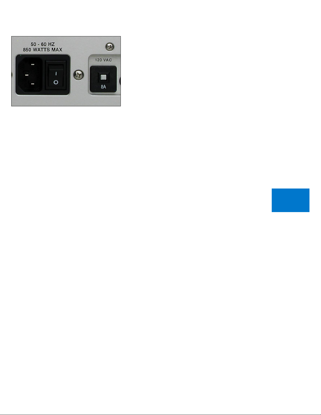
Your 860 Stereo Power Amplifier is supplied with a mains cord
suitable for the location where it was purchased. It is constructed of a
large enough wire gauge and a cable plug appropriate for the voltage
you intend to use. Do not substitute another power cable.
The voltage appears on the rear panel. If you require a different AC
mains voltage, contact your dealer immediately.
Exact voltage and frequency compatibility is stated in the
specifications section.
Once the 860 Stereo Power Amplifier is connected to a live mains
outlet and the mains power switch turned on, the front panel indicator
will be illuminated. The indicator will be of varying color, showing that
the supervising microprocessor is powered up and ready.
1-2
GETTING
STARTED
Page 8
CONNECTING A BALANCED SOURCE
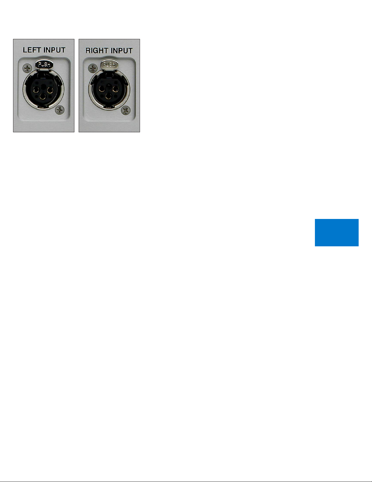
To fully realize the sonic potential of your 860 Stereo Power Amplifier,
use balanced connections whenever possible. Balanced cables reduce
interference from magnetic and RF sources to an absolute minimum.
Connect your preamplifier or source outputs to the inputs
provided.
1-3
GETTING
STARTED
Page 9
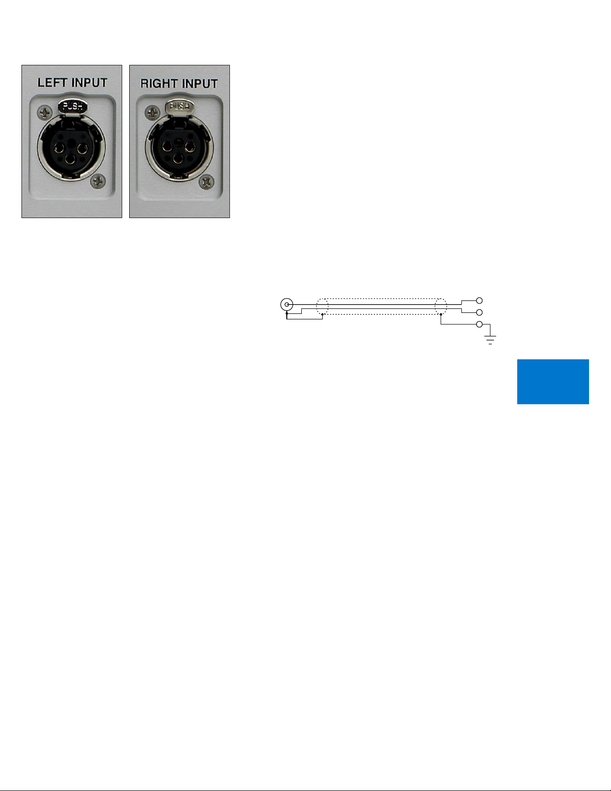
CONNECTING AN UNBALANCED SOURCE
UNBALANCED INPUT CABLE
3-NEG INPUT
2-POS INPUT
1-GROUND
Although the input connectors are of the three-pin XLR type, an
unbalanced source is easily accommodated by using a special cable. This
cable has an RCA phono type connector on the source end and a threepin XLR connector to go to the input of the 860 Stereo Power Amplifier.
The negative input (Pin 3) should be wired to ground only at the
RCA phono connector. This brings the negative input reference of the
860 to the unbalanced source ground, thus reducing ground loops.
Another option for accommodating unbalanced sources is to use
Boulder ABL2 Input Adapters. They convert a balanced input into an
unbalanced RCA phono input right at the rear of the 860.
Like the above cable, the negative input of the 860 is connected to
the ground of the RCA connector. However, the negative side will then
share the shield wire with the chassis ground and will not have very
good hum rejection.
1-4
GETTING
STARTED
Page 10
POLARITY
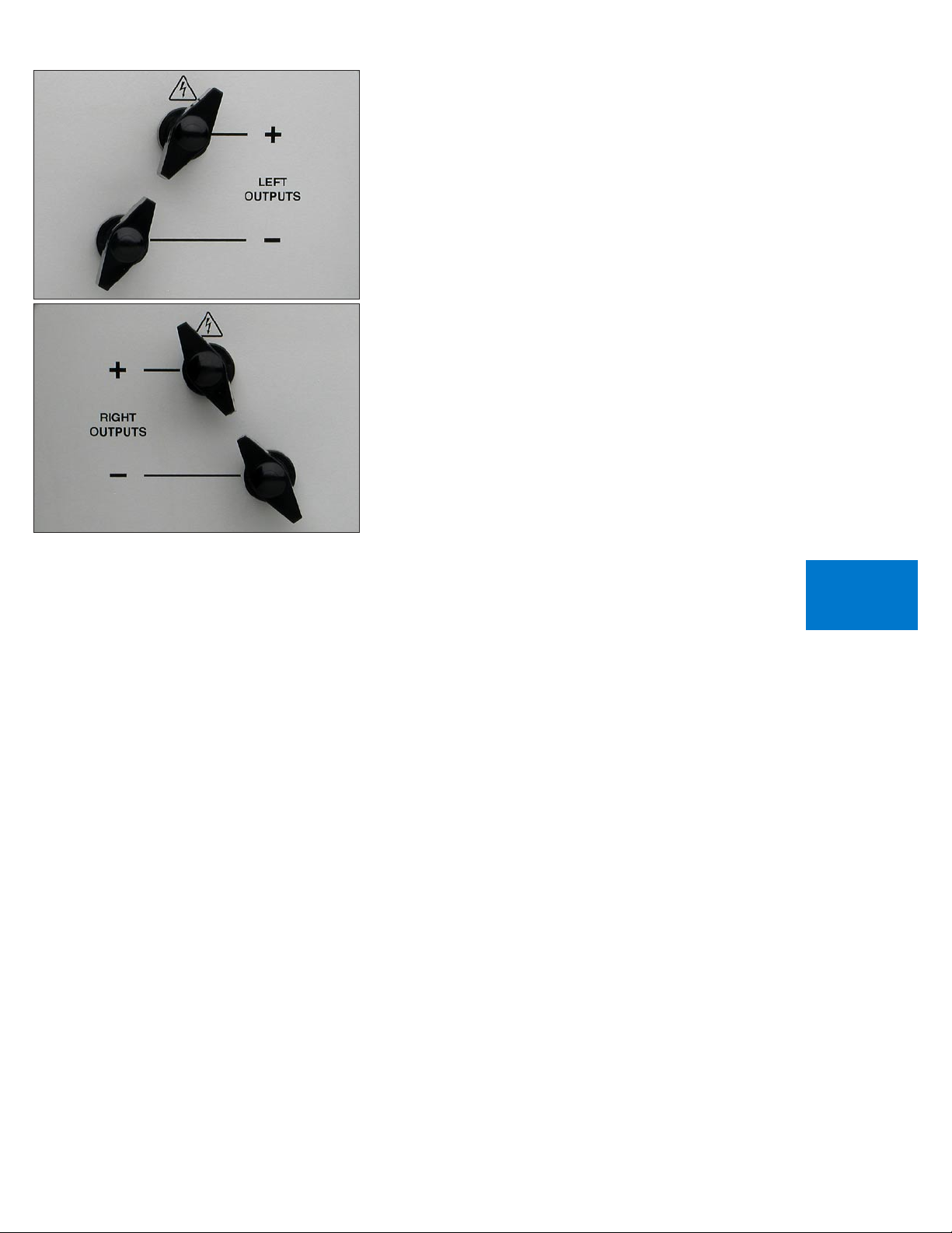
Please note that the 860 Stereo Power Amplifier conforms to the
standard of Pin 2 as the high or ”hot” for the balanced inputs.
The polarity of the 860 Stereo Power Amplifier is such that a positivegoing transition at Pin 2 will produce a positive-going transition at the
“+” output terminal.
CONNECTING YOUR LOUDSPEAKERS
Do not use any wrenches on the loudspeaker binding posts! Tighten
these connectors only by hand.
WARNING: This is a high power amplifier! When driven, there is a
high voltage potential at the terminals.
Connections should only be made with the AC mains disconnected!
Select spade terminals which accept 6 mm or .250 inch diameter
binding posts.
There is no provision for the use of banana plugs. These plugs have
been proven to come loose over time which increases contact resistance
and distortion. For the same reason we also do NOT recommend the use
of banana plugs at the loudspeaker end.
1-5
GETTING
STARTED
Page 11
OP ERATION
POWERING UP
With all your connections made, you are ready to listen to your
Boulder 860 Stereo Power Amplifier.
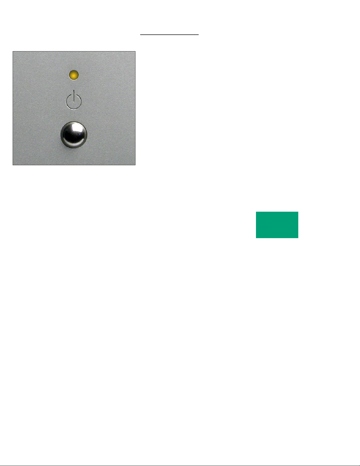
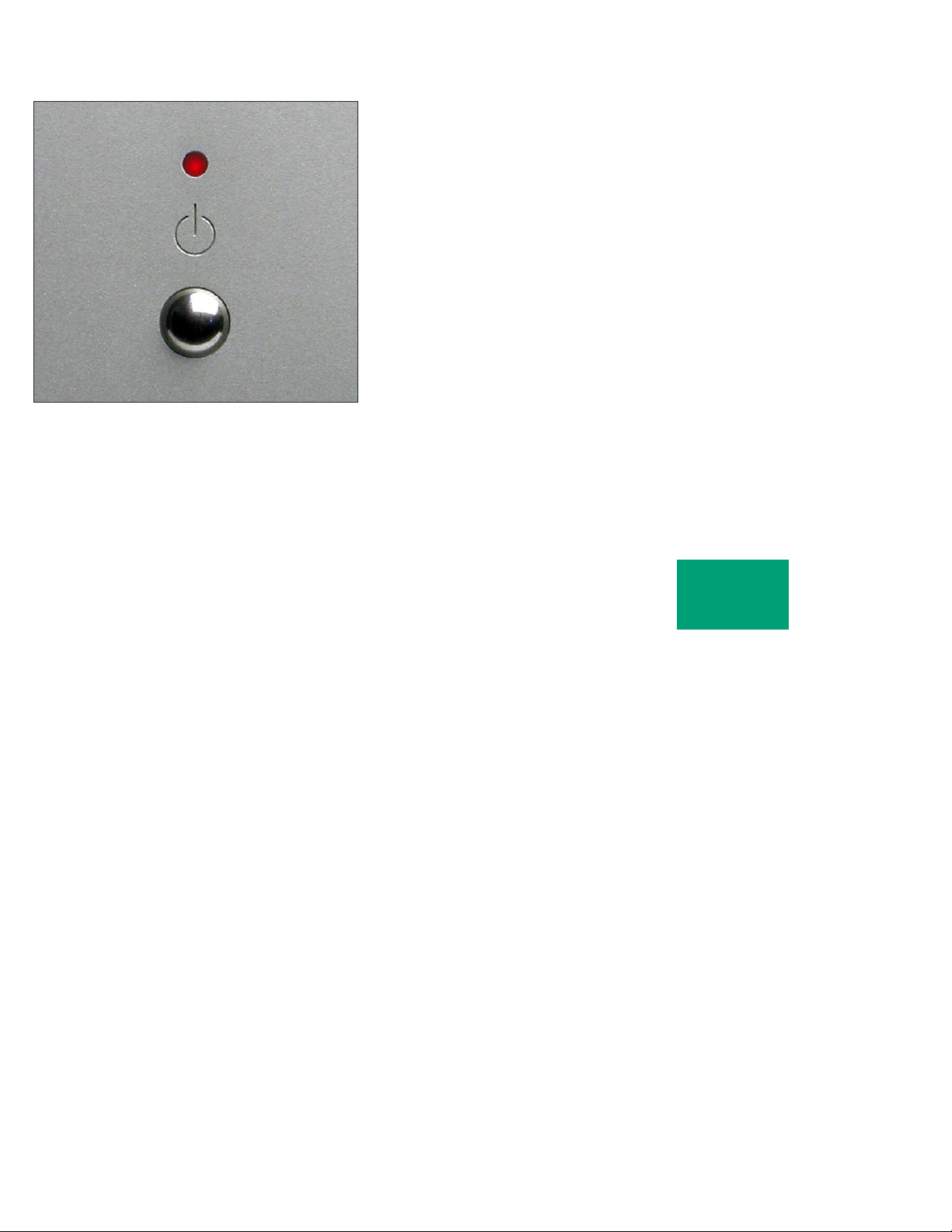
To turn the amplifier on, press the STANDBY button on the front
panel. The amplifier will perform a warm up cycle and the indicator
will alternate between red and amber for 45 seconds. This power up
sequence can be skipped by pressing and holding the STANDBY button
until the indicator turns red; then release and it will start in about five
seconds.
To reduce the inrush of electrical current during power-up, relays
are used to turn on the amplifier in stages. These are under the control
of the supervising microprocessor. During the power up sequence, you
will hear a relay click followed by an additional relay click after two
seconds.
The indicator will then turn and remain amber during normal
operation.
To turn the amplifier off, press the STANDBY button again. The
indicator will continuously change from red to green.
2-1
OPERATION
Page 12
CLIP DETECTION
Clipping of the waveform results when any amplifier is driven at too
high a level. A clip detection circuit is included in the 860 Stereo Power
Amplifier.
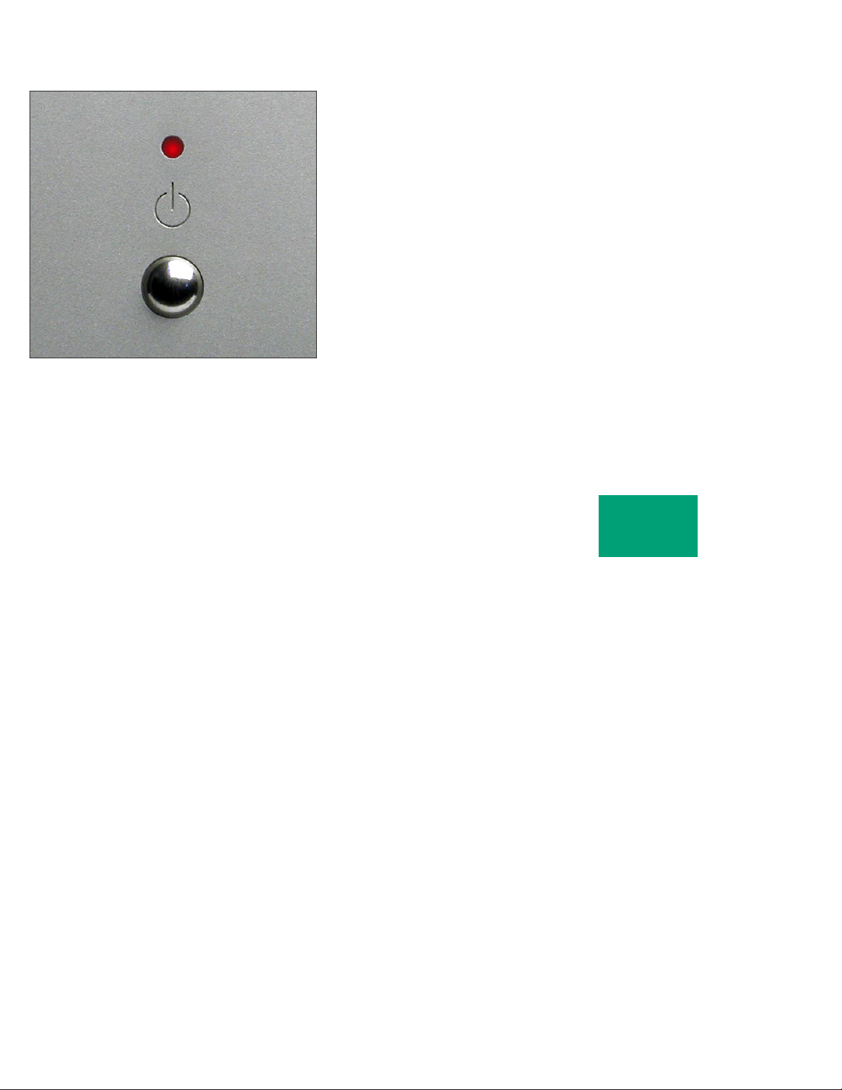
The indicator will indicate clipping by momentarily turning from
amber to red. Both voltage and current modes of clipping will be
detected, although generally it is only voltage clipping which occurs.
2-2
OPERATION
Page 13
SHORTED OUTPUT DETECTION
If the output of the amplifier becomes shorted, the front panel
indicator will turn red and the amplifier will turn off the output stage
for about three seconds, then very briefly try to turn on again. If the short
still exists, this cycle will repeat until the short circuit is removed.
THERMAL PROTECTION
A thermal protection circuit prevents high case temperatures which
are unpleasant to the touch and potentially harmful to the amplifier. The
thermal cutout circuit will mute the amplifier when the transistor cases
reach 85°C, and the indicator will turn red.
If this happens, more ventilation should be provided for the
amplifiers.
MAINTENANCE
No routine maintenance is required for the Boulder 860 Stereo Power
Amplifier. However, to keep operating temperatures at a minimum, do
not block the heat sinks, and remove any dust buildup that may occur.
2-3
OPERATION
Page 14
RE MOTE CO NTROL OP ER ATION
Operation of the Boulder 860 Stereo Power Amplifier by remote
control is possible when connected by a Boulderlink cable to other
Boulder preamplifiers or CD players.
When so connected, the 860 Stereo Power Amplifier will be turned
on and off with the other component.
12 VOLT TRIGGER
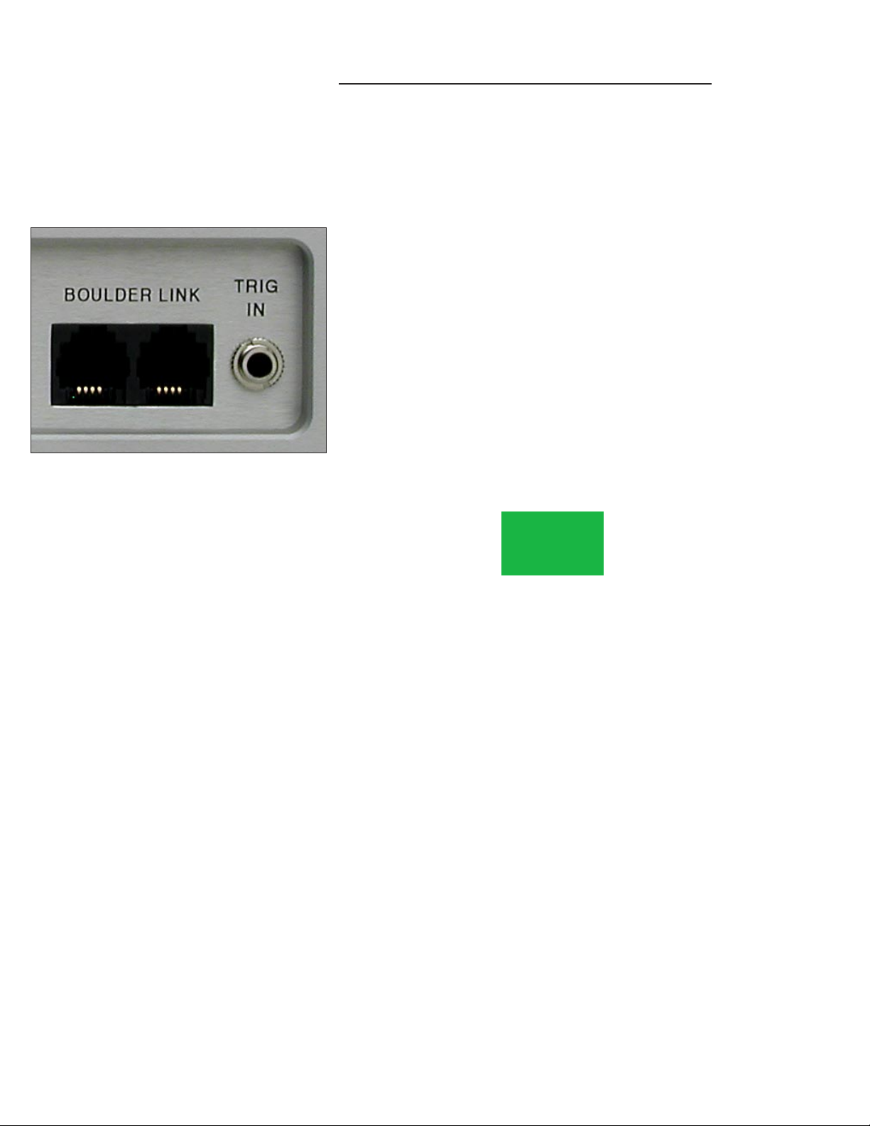
The 860 Stereo Power Amplifier also provides a trigger input for
remote on/off operation with other brands of equipment. With a trigger
connection, the 860 will be on when the voltage is +5 to +12 volts, and
off when the voltage is 0 volts. The tip of the mini phone plug should be
positive with respect to the sleeve.
When the 12 Volt Trigger is used, the 860 Stereo Power Amplifier will
be turned on in the sequence set by the ID switch. See page 4-2.
WARNING: Boulderlink and the trigger input should never be used
at the same time.
3-1
REMOTE
CONTROL
Page 15
BOULDERLINK "DAISY CHAIN"
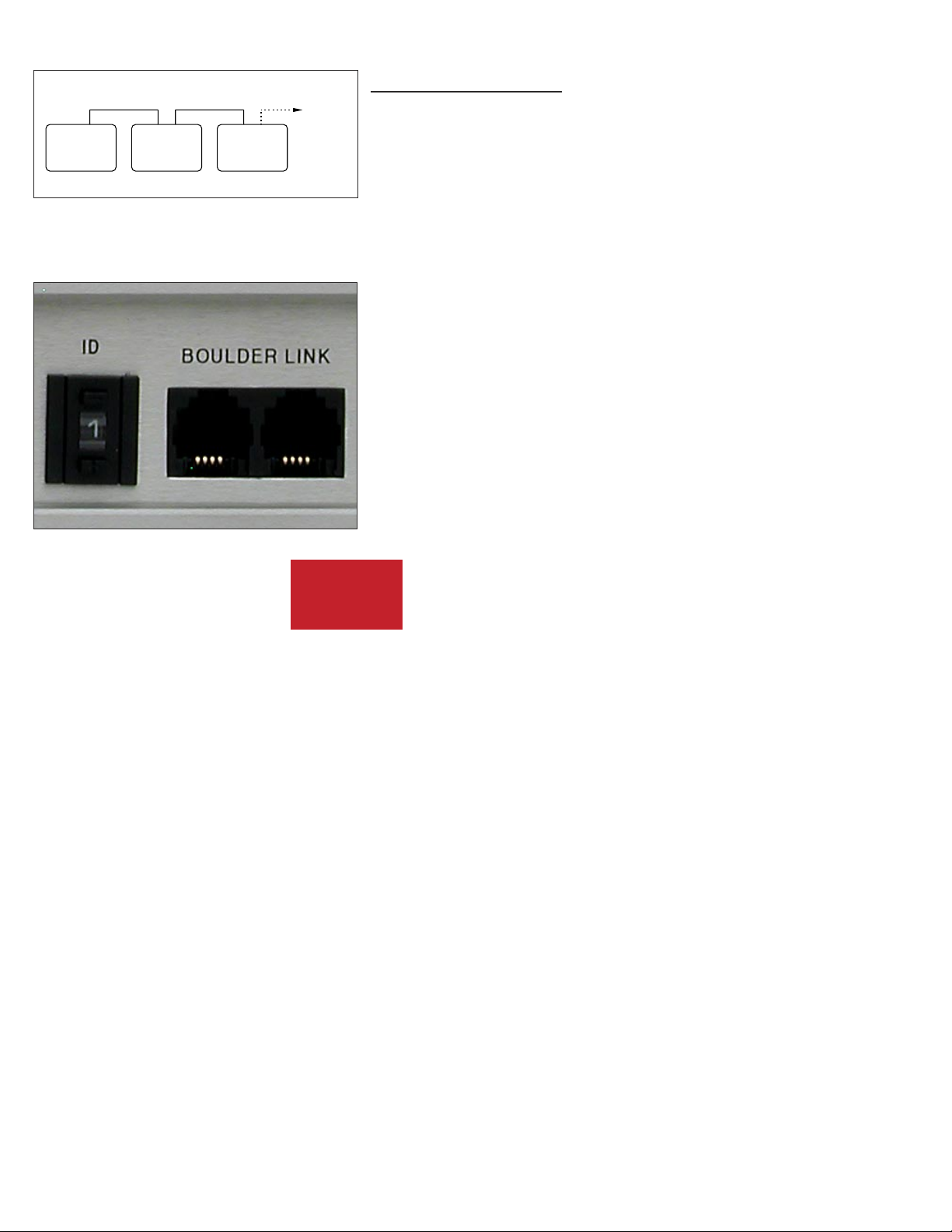
TO ALL
OTHER
SLAVE
UNITS
BOULDER
PRE-
AMPLIFIER
BOULDER
POWER
AMPLIFIER
BOULDER
POWER
AMPLIFIER
MASTER SLAVE SLAVE
BO ULDER LI NK
Boulderlink is a means of interconnecting most Boulder products
so that their microprocessors can talk to each other and pass important
information. Among the key features, Boulderlink allows sequential
initiation of power amplifiers’ and other products’ power up when the
”master” component is turned on. Boulder power amplifiers can send
messages to certain other Boulder products which are then shown on
the display.
CONNECTING BOULDERLINK
Turn off all products to be linked before connecting any Boulderlink
cables and setting the Boulderlink ID and Master/Slave switches.
Two connectors are provided on the back of the 860 and other
Boulderlink enabled products. Boulderlink cables in various lengths are
available as an accessory from your Boulder dealer.
All the chassis are connected together in a daisy chain manner. Start
by connecting one chassis to another, then from that chassis to the next
until all are connected. The order does not matter.
A special interface may be obtained to enable Boulderlink to be used
with other automation and control systems. Contact your Boulder dealer
for details.
4-1
BOULDER
LINK
Page 16
SETTING BOULDERLINK SWITCHES
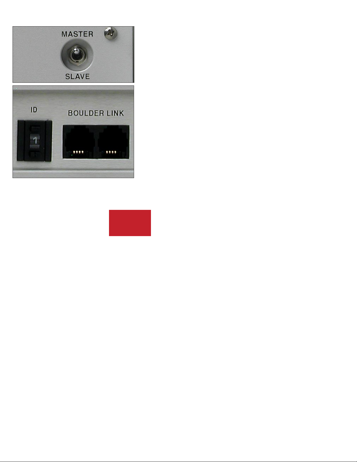
Every Boulderlink system must have one “MASTER” component,
and only one component can be set to MASTER. This is usually
the preamplifier. Power amplifiers and other products not having a
MASTER/SLAVE switch are not eligible to be “MASTER.”
SETTING BOULDERLINK ID NUMBERS
Every component is required to have a unique Boulderlink ID
number.
Each Boulder 860 Stereo Power Amplifier has a thumbwheel switch
on the rear panel. Start by setting the switch on the first amplifier to 0
or 1 and then increment up from there without any duplication. Use of
the lowest numbers will speed up turn-on as each amplifier is allowed
about three seconds before the next. This spreads out the power line
inrush currents thus preventing house circuit breakers from unnecessary
tripping. Up to 16 power amplifiers may be connected together in one
Boulderlink cable daisy chain.
4-2
BOULDER
LINK
Page 17
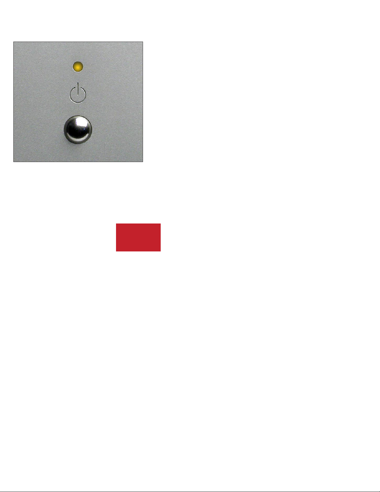
POWER UP VIA BOULDERLINK
With each component connected together by a Boulderlink cable, and
individually connected to the mains, pressing the master’s STANDBY
pushbutton will initiate the turn on sequence of all components.
The first time a master is powered up, it will search for any “slave”
units connected to it. As the master finds each slave, the slave’s ID
number will be shown on the display.
If any of the connected slaves are amplifiers, then each time the master
is turned on it will display “WAITING FOR AMPS.” Each amplifier will
be turned on in the order of their Boulderlink ID. To minimize turn on
time, the amplifier Boulderlink IDs should be set to the lowest sequential
numbers possible. For example, use 0, 1, and 2 instead of 13 , 14, and 15.
An amplifier set to ID 15 will take 47 seconds to turn on.
4-3
BOULDER
LINK
Page 18
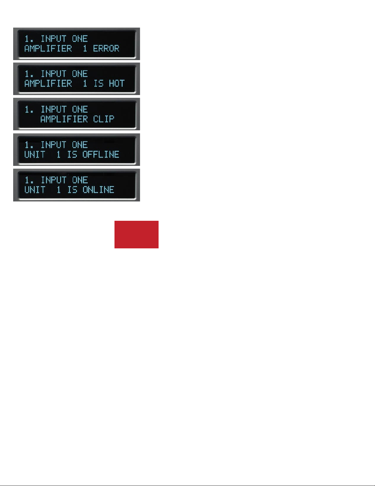
BOULDERLINK MESSAGES
Each component in the system can send a message to the
preamplifier which is then shown on its display. This is particularly
helpful in confirming the operating status of each power amplifier in
a multiple amplifier system. Typical messages on an 810 Preamplifier,
1010 Preamplifier or 1012 DAC Preamplifier are as follows.
“AMPLIFIER 1 ERROR” means that an internal power supply has
failed and the amplifier has turned itself off to protect the speakers from
damage.
“AMPLIFIER 1 IS HOT” means that is has turned itself off due to a
higher than normal temperature condition on the heatsinks.
“AMPLIFIER CLIP” means that the amplifier’s output has
momentarily reached its voltage limitation.
“UNIT 1 IS OFFLINE” means that the slave is no longer responding
via Boulderlink. Its Boulderlink cable may have become disconnected, or
the mains power has been disconnected.
“UNIT 1 IS ONLINE” means that the slave is now responding
via Boulderlink in a normal manner and has been recognized by the
master.
4-4
BOULDER
LINK
Page 19

BO ULDER 8 60 ST EREO PO WER A MPLIF IE R SPE CIFIC ATI ONS
THD at Continuous Power, 20 to 2KHz 0.0035%
THD at Continuous Power, at 20KHz 0.018%
Continuous Power, 8 Ω 150W
Continuous Power, 4 Ω 150W
Peak Power, 8 Ω 150 W
Peak Power, 4 Ω 300 W
Magnitude Response, 20 to 20KHz +0.00, -0.04 dB
Magnitude Response, -3 dB at 0.015Hz, 150kHz
Voltage Gain 26dB
Signal to Noise Ratio (re: 500W/8Ω) -108dB, unweighted, 20 to 22kHz
Input Impedance Balanced: 50KΩ, Unbalanced: 25KΩ
Common Mode Rejection (Balanced only) 60Hz: 90dB, 10kHz: 70dB
Inputs 3-pin Balanced
Output Connectors 6 mm / .250 inch thumbscrews
Crosstalk, L to R or R to L Greater than 112dB
Size, Inches, Width X Height X Depth 17.0W x 7.38H x 15.25D Speaker connectors add 1.50 to depth
Power Requirements Voltage suitable for country where sold
50-60 Hz, 850 W at maximum
All specifications taken at 120 VAC mains power
5-1
APPENDIX
Page 20

TROUBLESHOOTING
SYMPTOM CAUSE REMEDY
No power indication Power switch is not on Turn on rear panel power switch
Power amplifier is not plugged in Connect to an AC outlet
Home circuit breaker is tripped Reset circuit breaker
Fuse on rear panel blown Replace fuse
Red power indication Low line voltage Have line voltage checked
Power supply breaker tripped Reset breakers on rear panel
Defective amplifier Return to dealer for service
Amber power indication, but sound not
heard from one channel
No signal from one channel of source Check source controls, cables, and
connections
One channel is muted by balance control Recenter balance on preamp
No signal out to power amplifier Check connections to power amp
5-2
APPENDIX
Page 21

NOTES
5-3
APPENDIX
 Loading...