

Page 1
modelmodel
101101
MICROPHONE PREAMPLIFIER
OWNERS MANUAL
PO Box 204 Boulder, CO. 80306
voice: 303.443.7454 fax: 303.444.4634
email: [email protected] web: www.gracedesign.com
Revision B April, 2001 © Copyright 2000, Lunatec LLC
HI Z
48V HPF
1OdB
GAIN
6OdB
-1OdB
TRIM
OdB
POWER
Page 2

Thank you for purchasing the Model 101 microphone
preamplifier. It is designed to be extremely reliable and easy
to use. However, we ask that you take the time to familiarize
yourself with some of the more important operation
instructions in this manual to avoid most common user
problems.
Regardless of what audio sources you plan to record,
the Model 101 will faithfully serve as an invisible link between
your microphone or instrument and recording device. We
hope it helps you achieve a new level of excellence in your
audio recordings.
Feel free to check out internet web page for the latest
information regarding your preamplifier. You can always find
the latest owners manuals and other technical documents at:
http://www.gracedesign.com/documents/docs.html
Grace Design has been building high quality professional
audio products for the recording industry for over ten years.
During this time the circuit technology in the Model 101 has
evolved through a process of extensive listening, testing and
refinement.
Your new Model 101 represents a dramatic
breakthrough in delivering absolutely pristine audio
performance, robust mechanical construction and bombproof
reliability at an affordable price.
1
Page 3

MODEL 101 FEATURES
• Fully balanced transformerless mic input and high
impedance instrument input
• Balanced XLR and 1/4" TRS outputs
• Ultra clean 48 Volt phantom power
• 11 position precision silver contact rotary gain switch
• High quality conductive plastic 10dB output attenuator
• 75Hz 12dB/octave transitional Thompson-Butterworth high
pass filter
• two color LED peak meter shows signal present and peak
conditions
• No electrolytic capacitors in the signal path.
• Minimal internal signal wiring
• Ultra high resolution transimpedance gain stage
• High precision active balanced output circuit
• Gold plated XLR input and output connectors
• Sealed gold contact relay for instrument/mic switching
2
Page 4

FRONT PANEL CONTROLS
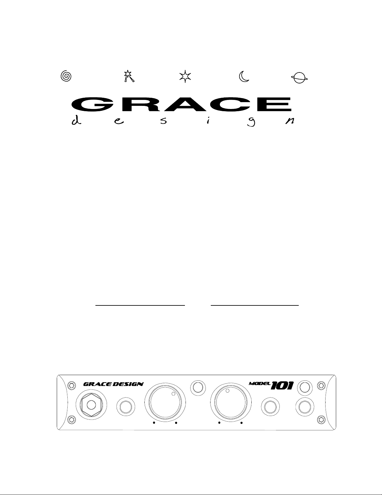
GAIN CONTROL Each gain control has 11 positions and adjusts the voltage
gain on the microphone input from 10dB to 60dB in 5dB steps. When using
the instrument input, the gain range is –10dB to 40dB in 5dB steps.
NOTE: If you ordered the high gain version of the 101 for use with ribbon
microphones, the gain range of your unit on the microphone input is 20dB to
70dB in 5dB steps and the gain range of the instrument input is 0dB to 50dB in
5 dB steps.
TRIM CONTROL The trim control provides 10dB of continuously variable
output attenuation. In the fully clockwise position the trim is at unity (no
attenuation). In the fully counter-clockwise position the trim is at -10dB. For
reference, the 3 o’clock position is -4dB and the 12 o’clock position is -8dB.
The trim control should be left in the fully clockwise position during normal
recording.
48V PHANTOM POWER This switch provides 48 volts to power condenser
microphones. The phantom power switch (labeled +48) connects the +48V
power supply to pins 2 and 3 on the XLR input connector.
PEAK INDICATOR The LED peak indicator, which monitors the signal
between the input and output amplifiers, illuminates the green LED at -20dBu
and illuminates the red LED at +16dB (10dB before clipping). It is located
between the GAIN and TRIM controls.
HIGH PASS FILTER (labeled HPF) Sometimes referred to as a bass roll-off,
the high pass filter rolls off at 75Hz. This 12dB/octave filter employs a
transitional Thompson-Butterworth response for the best combination of
passband flatness and time domain response.
POWER SWITCH The power switch connects power from the DC input
connector to the preamplifier circuitry. When depressed, the amber POWER
LED will illuminate.
3
Page 5

CONNECTING THE PREAMPLIFIER
AUDIO CONNECTIONS
l Microphone input connections are made using the female XLR connector
on the rear panel. This connector is wired with pin 2 positive, pin 3 negative
and pin 1 ground. 48V phantom power, if used, is supplied on pins 2 and 3.
l Instrument or line input connections are made using the ¼” TRS jack on
the front panel. This connector is balanced with the Tip positive, Ring
negative and Sleeve ground.
l When a jack is inserted into the instrument input, a sealed gold contact
relay switches the preamplifier input source from the mic input connector to
the front panel TRS jack. The input impedance of the instrument input is 1M
Ohm, which is ideal for inserting high impedance sources such as guitars with
passive pickups as well as any instrument with a high level output. Please
note that the gain range of the preamplifier when using the instrument input is
–10dB to +40dB.
l Using the instrument input with an unbalanced source is simple if a mono
¼” jack is used since the sleeve will automatically ground the inverting input
(ring) when plugged in.
l Output connections are made using the male XLR connector or the ¼”
TRS jack. The XLR connector is wired with pin 2 positive, pin 3 negative and
pin 1 ground. The ¼” TRS connector is balanced with the Tip positive, Ring
negative and Sleeve ground. The XLR and TRS outputs can be used
simultaneously. Important- See figures 1. and 2. for unbalanced cable
termination information.
l If either of the outputs are to be used unbalanced, a modified cable is
required and pin 3 (or the Ring) should be left open. See figure 2. below.
NOTE: It is not recommended to use an unbalanced ¼” plug in the TRS output
jack since the sleeve of the unbalanced plug will short the inverting output
amplifier to ground. While this will not cause damage to the preamplifier, it
can cause distortion in the unbalanced signal.
4
Page 6
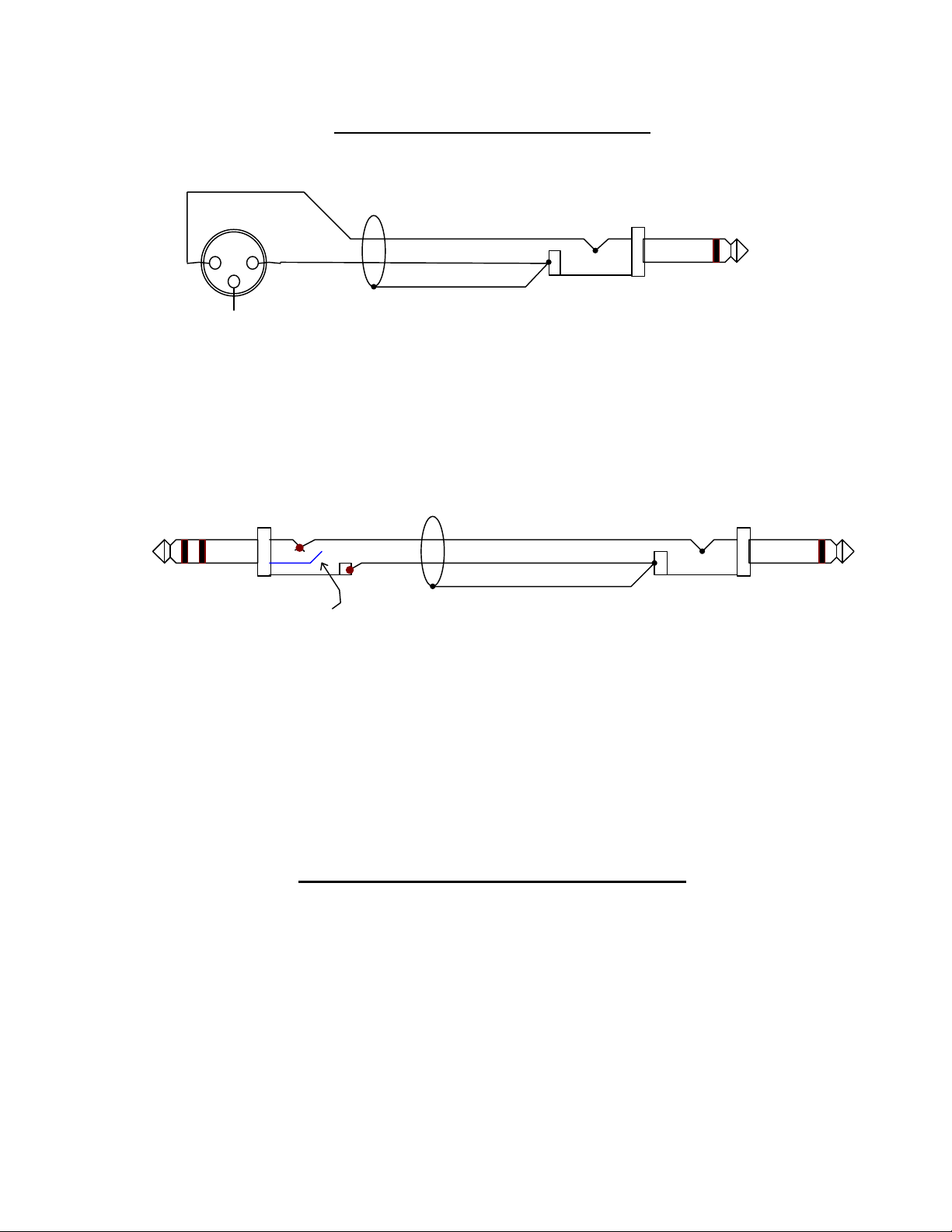
Cable Termination Diagrams
HOT
2
3
(OPEN)
1
GND
SHIELD
Figure 1. XLR UNBALANCED OUTPUT CABLE TERMINATION
PREAMP END
TIP
RING
RING IS OPEN
SLEEVE
HOT
GND
SHIELD
Figure 2. TRS UNBALANCED OUTPUT CABLE TERMINATION
POWER SUPPLY CONNECTIONS
A 2.1mm jack is used for the DC power input of the 101. The polarity of the
jack is positive in the center and ground on the outside.
Included with your Model 101 is an AC adapter rated for 6VDC @ 800mA.
5
Page 7

OPERATION
SETTING THE GAIN
l Turn the gain control fully counter-clockwise, turn the trim control fully
clockwise and check that the +48V phantom power is off.
l Connect the microphone to the preamplifier and then turn on the phantom
power switch on if required.
l When sending a signal to a recorder that has fixed input levels, simply
increase the gain until the optimum recording level is reached.
When sending a signal to a tape recorder with a variable input, use the
following procedure:
l Turn the gain control fully counter-clockwise, turn the trim control fully
clockwise.
l Set the record level control on the recorder to 12 o’clock or midway
between minimum and maximum.
l With the sound source present, turn the preamplifier gain control clockwise
until the peak LED begins flashing red, then reduce the gain until the red stops
flashing.
Since red indicates a peak level which is 10dB before clipping, it is OK for it to
come on occasionally during recording.
l Adjust the recorder input control for the optimum recording level.
About the Trim Control
The trim control can be used for fine output level adjustment as well as for level riding
during recording. It should be noted that the maximum output level of the preamplifier is
reduced by the amount of output attenuation (trim control) being used. For instance, if the
trim is set to -6dB, the maximum output level of the preamplifier will drop from +26dBu to
+20dBu. Since the LED peak indicator monitors signal level before the trim control it, will
always monitor the actual preamplifier headroom regardless of the trim control setting. It is
best to leave the trim control fully clockwise for normal recording operations. This ensures
that the preamplifier will be operated at the minimum necessary gain setting.
6
Page 8

Model 101 Specifications
GAIN RANGE
Mic input 5dB steps 10-60dB
Mic input 5dB steps High gain version 20-70dB
Hi-Z input 5dB steps -10-40dB
Hi-Z input 5dB steps High gain verzsion 0-50dB
Output trim attenuator 0 to -10dB
THD+N
@20dB Gain +20dBu out <0.00085%
@40dB Gain +20dBu out <0.0010%
@60dB Gain +20dBu out <0.0050%
IMD (SMPTE/DIN 4:1 7kHz/50Hz)
@40dB Gain +20dBu out <0.0020
NOISE (EIN)
50 Ohm source <-130dB
150 Ohm source <-128dB
600 Ohm source <-124dB
CMRR
100Hz >68dB
1kHz >75dB
10kHz >65dB
PHASE DEVIATION (HPF off)
50Hz-25kHz <6 degrees
FREQUENCY RESPONSE
Mic input @40dB Gain -3dB 4.5Hz-400kHz
Mic input @40dB Gain -0.5dB 12Hz-170kHz
Hi-Z input @20dB Gain -3dB 3.0Hz-300kHz
Hi-Z input @40dB Gain -0.5dB 7.5Hz-300kHz
IMPEDANCE
Mic input 1600 Ohms
Hi-Z input (unbalanced) 1.0M Ohms
Hi-Z input (balanced) 2.0M Ohms
PEAK LED METER
Green threshold -20dBu
Red threshold +16dBu
MAXIMUM OUTPUT LEVEL
100k Ohm load, 0.1% THD +25dBu
CROSSTALK None!
7
Page 9
d
B
u
d
B
u
+1
0
-1
-2
-3
20
+20
0
-25
-50
-75
-100
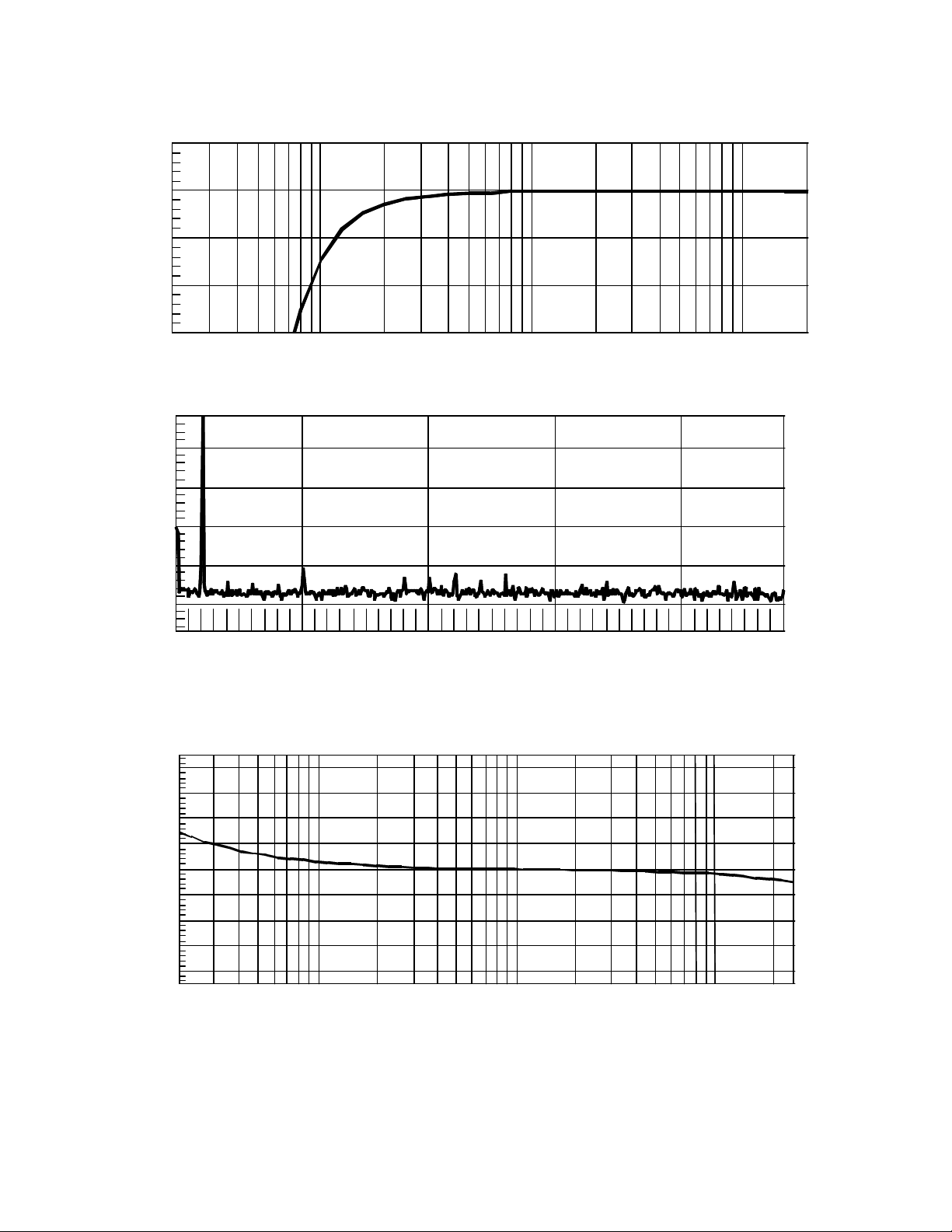
75Hz HIGH PASS FILTER RESPONSE
50 100 200 500 1k 2k 5k 10k 20k
FFT SPECTRUM ANALYSIS
d
e
g
+40
+30
+20
+10
0
-10
-20
-30
-40
5k
10k
FFT @40dB gain, +20dBu out
Hz
15k
20k
PHASE vs FREQUENCY
20
50 100 200 1k 500 10k 2k 5k 20k
Hz
Phase response @10dB gain. 50 Ohm source, 100K Ohm load, HPF Off
25k
8
 Loading...