

Page 1
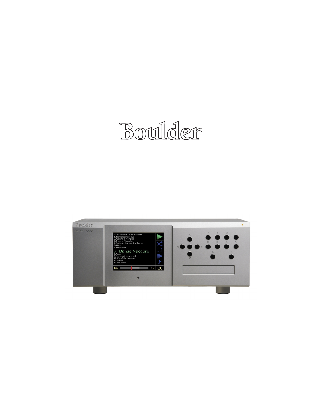
1021 Disc Player
Owners Manual
Introduction
Safety
Awareness
Unpacking
The 1021
AC Mains
Voltage
1021 Rear
Panel
1021 Front
Panel
Installing
The 1021
Connecting
The 1021
Page 2

II
Page 3

III
Thank You
We at Boulder Ampliers would like to thank you for selecting the
1021 Disc Player for your audio System.
The 1021 represents the concerted efforts of numerous Boulder
craftsmen, designers, engineers, and technicians working to bring
you the very nest audio playback components in the world; and we
are certain it will provide years of enjoyment.
Please take a few minutes to read through this owner’s manual
prior to the installation and use of your 1021. This will help you to
understand the basic functions and abilities of the Disc Player, and
allow you to maximize the exceptional performance for which it was
designed.
Boulder Amplifiers, Inc. • 3235 Prairie Ave.
Boulder, CO 80301 • USA
Page 4

IV
Table of Contents
Thank You 3
Introduction 1-1
Features of the 1021 Disc Player 1-1
Safety Awareness 2-1
Unpacking the 1021 3-2
Initial Inspection 3-2
Carton Contents 3-2
Removal of the 1021 from the Carton 3-2
AC Mains Voltage 4-2
Rear Panel of the 1021 5-2
LCD Display 6-2
Disc Tray 6-4
Status Indicator LED 6-6
Connecting the 1021 to Your System 7-2
Remote Control 8-2
Power Up or Active Mode 9-2
Playing a Disc 9-2
Basic Operation 9-2
Advanced Operation 10-2
Creating a Playlist 10-4
Options 10-6
Random Play 10-6
Repeat Play 10-8
Disc Scan Playback 10-10
Setup Tools 10-10
Setup and Programming 11-2
Main Setup Menu 11-2
Display Menu 11-2
Track List Menu 11-4
Audio Menu 11-10
Player Menu 11-14
Boulder Link Menu 11-20
Factory Reset Menu 11-24
Boulder Link 12-2
Using a Preamplier with Boulder Link 12-4
Connecting Boulder Link 12-4
Connecting Older Generation Products via Boulder Link 12-6
Setting Boulder Link Switches 12-6
Setting Boulder Link ID Numbers 12-6
Page 5

V
Table of Contents
Introduction
Power Up via Boulder Link 12-8
Boulder Link Messages 12-8
Specications 13-2
Warranty 14-2
Page 6

1-1
Features of the 1021 Disc Player
Every Boulder product far exceeds expectations, and to that end the
1021 is truly a Boulder. The design of the 1021 incorperates number of
innovations that elevated the performance of the 1021 well beyond
other players. These innovations in the include:
Introduction
Multiple format playback •
capabilities, including: MP3,
FLAC, OGG Vorbis, WAV, AIFF,
and standard CD (PCM) data.
Large, dimmable, full-color LCD •
display.
Automatic identication of artist, •
disc title, and track listing on
display.
Ethernet connectivity for •
downloading and updating of
track information.
Extensive setup and preferences •
menu.
Ultra-accurate disc drive •
mechanism for the best possible
reading of disc data.
Superior error correction and •
disc tracking software.
Proprietary DSP software for •
data extraction, processing,
volume control, buffering and
digital ltering.
Unique UpandOversampling DSP •
process increases digital bit rate
and word length to a minimum
of 24-bits and 352.8 kHz.
Boulder’s proprietary Eigen •
value digital lter algorithm for
unmatched digital ltering.
DSP implemented digital volume •
control allows direct connection
to ampliers.
Additional RAM implemented •
data buffer between DSP and
DAC section prior to reclocking
Boulder Precise Interval Clock •
located immediately adjacent
to DAC section to eliminate jitter
from the pre-converted data
stream.
Boulder 983 gain stage for •
exceptionally low distortion
voltage gain and analog
buffering.
Advanced oating point DSP •
system to prevent math overow
during processing.
Two pairs of parallel balanced •
outputs on XLR connectors.
AES standard digital output to •
feed outboard processors or
recording devices.
Boulder link connections for •
control and status indications
with other Boulder products.
IR input compatible with external •
control systems.
VGA video output connector •
for use with secondary display
monitor.
Page 7

2-1
To reduce the risk of electrical shock or failure, • never expose
this product to rain, moisture, or damp conditions.
To reduce the risk of shock, • always use a properly
grounded three-conductor AC mains power cord. It is not
recommended that extension cords be used with the 1021.
Never• operate the 1021 with the top cover removed. There
are no user serviceable parts inside.
Never• attempt to repair the 1021 yourself. In the event
of a problem, please contact your authorized Boulder
dealer. Only qualied service personnel should attempt the
disassembly or repair of any Boulder product.
Never• attempt to modify, alter, or otherwise change the
function or design of any Boulder product. To do so will
immediately void any warranty coverage.
Never• block or impede airow through the top cover or
around any heatsinks.
Never• expose the 1021 Disc Player to excessive heat.
Never• replace a fuse with a type or rating other than what is
specied by Boulder Ampliers.
Never• bypass any fuse or circuit breaker.
Always• disconnect the unit from the AC mains during
electrical storms.
Always• keep electronics out of the reach of children or pets.
Safety Awareness
Introduction
Safet y
Awareness
Page 8
3-1
Page 9

3-2
Initial Inspection
Inspect the shipping container for damage. If the shipping carton,
packing materials, player, or accessories are damaged or missing,
notify your dealer immediately.
Note: many shippers require notication and inspection within
tewnty-four (24) hours of delivery to determine the nature of
damaged incurred.
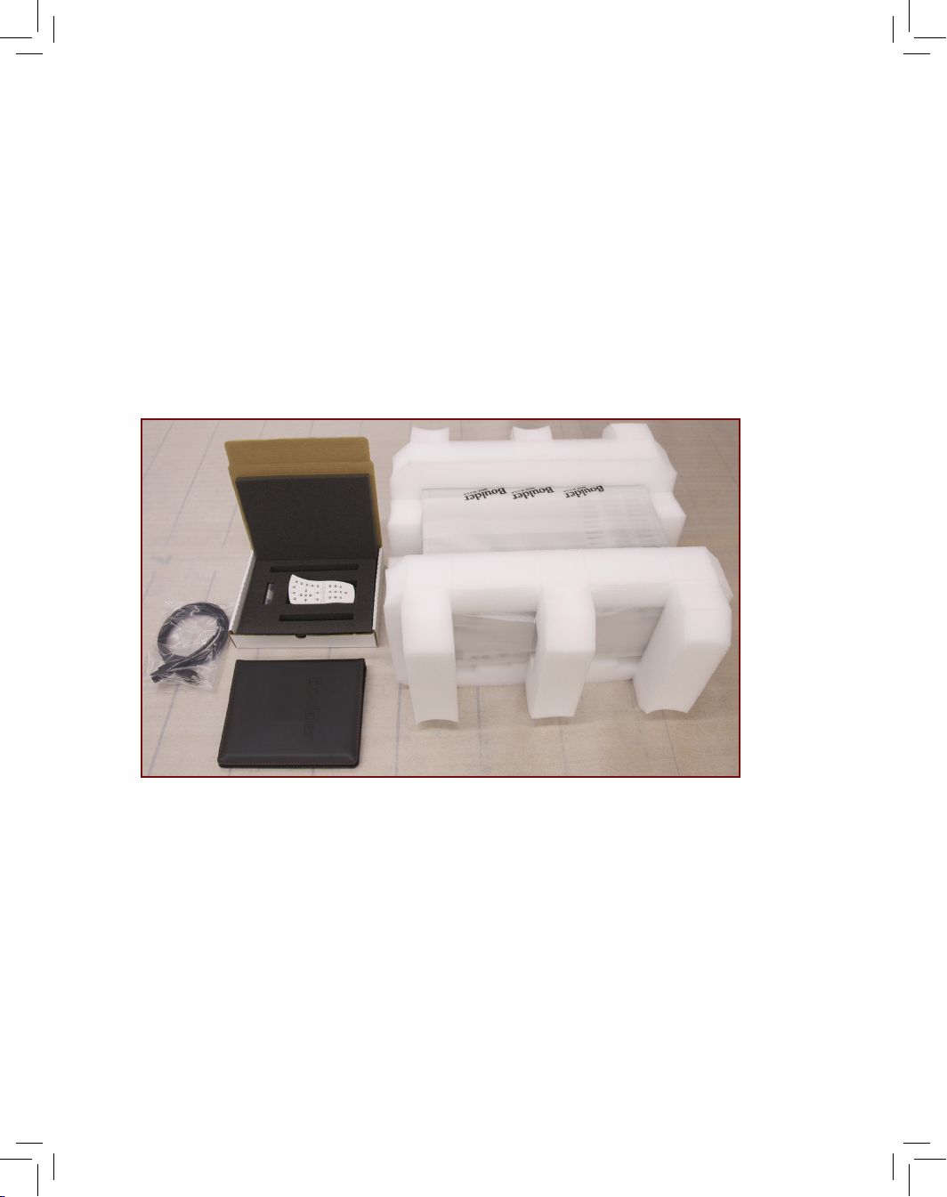
Carton Contents
The following items should be included with the 1021:
One (1) AC Mains power cord suitable for use in your location. 1.
One (1) Accessory Kit containing: 2.
One (1) Remote Control. a.
One (1) Instruction Manual. b.
Three (3) AAA batteries (in the Remote Control). c.
Removal of the 1021 from the Carton
The 1021 Disc Player has been securely packed to guard against damage during transport. Double boxing has been selected for maximum
protection. In order to install the 1021, both boxes must be opened and
the unit removed from the inner box. Be sure to open the 1021 near the
place where it will be installed so that it does not have to be carried.
Once you have opened to boxes, follow the instructions below.
Note: the 1021 is heavy. It is advisable that two people remove the
unit from the cartons.
Turn the box on one of its sides so that the open end is facing 1.
sideways.
Slide the 1021 out of the carton and towards the location 2.
where it will be installed.
Unpacking the 1021
Unpacking
The 1021
Page 10

3-3
Page 11

3-4
Remove each of the foam end-caps. 3.
Lay the unit so that it is at and the sealing tape is facing 4.
upwards.
Pull the tab on the end of each piece of tape so that the 5.
foam inner-wrap can be easily removed.
Remove the foam wrap and lay the 1021 at on its feet. 6.
Inspect the 1021 for any damage. 7.
We strongly suggest that you save all the packing materials. If
the 1021 must be returned to your dealer or to Boulder Ampliers,
the original packing material must be used for shipment to avoid
damage. Neither Boulder Ampliers nor the shipper can be held
responsible for damages incurred during transit if the original packing
is not used.
Unpacking the 1021
1021 Rear
Panel
AC Mains
Voltage
Page 12
4-1
Page 13

4-2
AC Mains Voltage
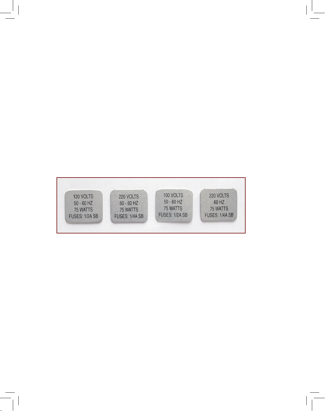
It is very important to check that the 1021 is congured for the proper
operating voltage. Damage to the unit may occur if it is connected
to the incorrect AC mains voltage.
Verify that the AC input identied on the rear panel as shown below
is the same as the AC mains voltage in your area.
Note: If the voltage does not match,
DO NOT
proceed with
installation or connect the 1021 to AC power and contact your
dealer immediately!
Page 14
5-1
Page 15

5-2
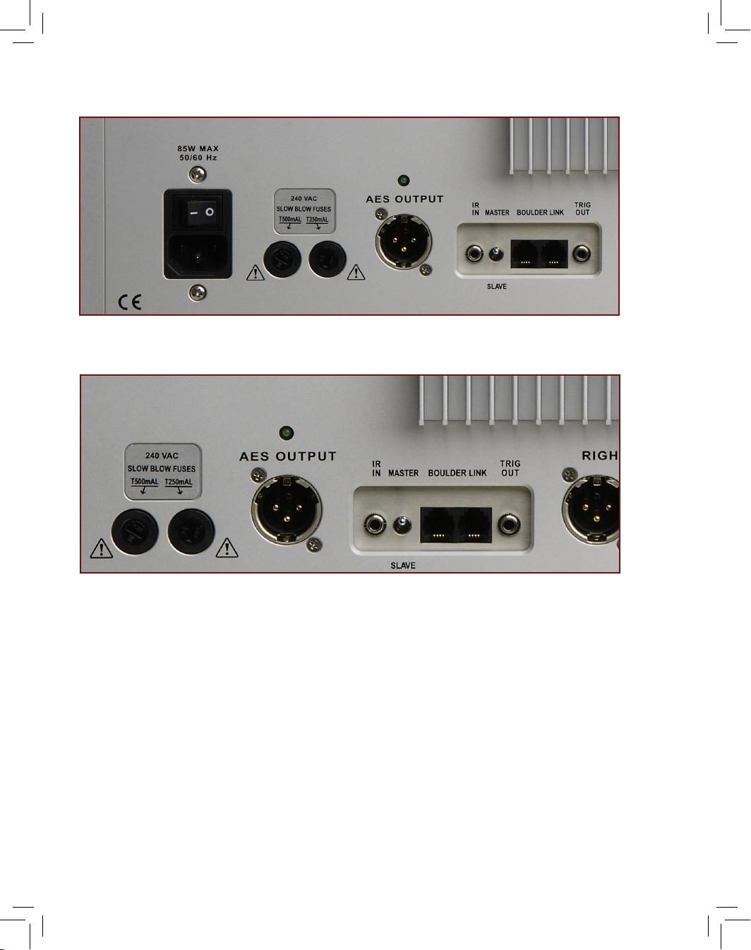
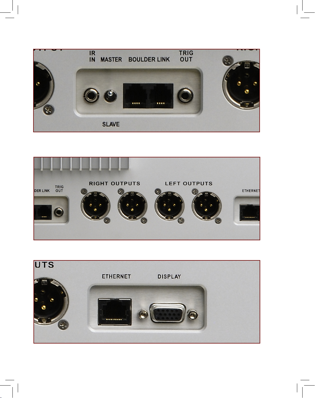
The following indications, connections and controls are present on
the rear panel:
Rear Panel of the 1021
Serial Number. 1.
The serial number of the unit is engraved on
the right-hand side of the rear panel. Write the serial number
here for your records: ___________.
AC Mains Power Connection. 2.
The 1021 AC mains power
connection is a grounded (three-prong) 15A IEC connector. It is
not recommended that the ground be lifted on the 1021.
Master AC Switch. 3.
This switch powers the 1021 ON or OFF.
Fuses. 4.
There are two fuse sockets on the rear panel to protect
the player from excessive current draw. Note: Never replace a
fuse with the incorrect rating or size.
Digital Output Connection. 5.
The 1021 features an AES3 digital
output connector to feed a digital server, recorder or separate
processor. The digital connection will output the native data
rate of the track being played.
IR Input Connections. 6.
The 1021 features an external IR input
if the front panel Infrared Remote Receiver is obstructed. The
1021 is also fully compatible with external control software such
as Crestron or AMX via the IR connection. Please contact your
dealer for further information regarding this connection.
Boulder Link Control and Connections. 7.
The 1021 can be
connected to other Boulder products for remote turn-on and
status indications. For further information regarding Boulder Link,
please see page 13-6.
12V Trigger Connections. 8.
The 12V trigger connection will
allow you to turn on an amplier with an equivalent connection
by simply turning on the 1021. The amplier will also turn off
when the 1021 is placed in Standby Mode. Please contact your
dealer for further information regarding this connection.
Analog Output Connections. 9.
These are the main outputs
of the 1021. There are two connectors per channel and each
1021 Rear
Panel
Page 16
5-3
Page 17

5-4
connection is of equal sound quality. Left channel connections
are marked “Left Outputs” and right channel connections are
marked “Right Outputs.” The 1021 can be connected to a
preamplier, processor, or directly to an amplier.
Ethernet Connection. 10.
The 1021 can be connected to your
home computer network to locate and download any missing
or available artist, track and album information for use on the
display. If the unit is not connected to the Ethernet, some data
may not be displayed properly.
External Display Connection. 11.
A separate connector is
provided so that the 1021’s display information can be shown
on a separate display, monitor, or control system. Please
contact your dealer for further information regarding this
connection. It is not advisable to use a plasma display with the
1021 for long periods of time as it may “burn in” the Track List on
the display.
The following features and controls are present on the front panel:
Rear Panel of the 1021
1021 Rear
Panel
Page 18
6-1
1
2
3
4
5
6
7
8
9/10
Page 19

6-2
Front Panel of the 1021
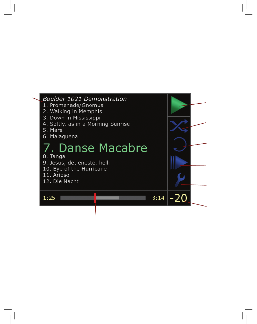
LCD Display.
The 1021 features a large, bright 6.5-inch (11cm) VGA display. Artist,
track, and album information as well as track list information is shown
here. The programming and setup menus are also displayed here. The
following features and icons are present on the 1021’s display:
Artist Name and Album. 1.
If available, the name of the
performing artist and album will be displayed here. In the event
of a data CD or disc with multiple MP3 albums on it, the title
given to the disc during the burning process will be displayed
here.
Track Listing. 2.
The names of each track will be listed here. The
track that is playing or that is cued to begin playing will always
be presented in green. It will usually also be enlarged to make
it easier to read. The enlarged text can be moved by scrolling
through the track list by using the navigation buttons, but
will return to the playing track if no action is taken within ve
seconds.
Play Status Indicator. 3.
This portion of the display shows the
current status of the player, whether in Play, Stop, Pause, Scan,
or Fast Forward, Fast Reverse or Skip modes.
Random Playback Indicator. 4.
This icon is green when the
Random Play mode has been selected. When random play is
not selected, the icon remains blue.
Repeat Play Indicator. 5.
This icon is green when one of three
Repeat Play modes (Repeat Track, Repeat Disc, or Repeat
A-B) is selected. When Repeat Play is not selected, the icon
remains blue.
Scan Mode Indicator. 6.
This icon is green when the scan
mode is selected. When scan mode is not selected, the
icon remains blue.
Setup Tools Indicator. 7.
This icon is green when setup mode
is selected. Pressing the Enter button while the icon is green
1021 Front
Panel
Page 20
6-3
Page 21

6-4
will navigate to the 1021’s setup menu.
Volume Display. 8.
The 1021 includes an internal DSP-based
volume control. With this the 1021 can be congured for
variable output to drive an amplier without the use of a
preamplier. This portion of the display always shows the
output level of the 1021 in decibels (dB).
Redline Display. 9.
The 1021 reads CDs in a unique way, always
reading data ahead of what you are actually listening to. The
Redline Display consists of three parts: the Progress Bar (dark
gray) shows the entire duration of the track, the point at which
the track is playing is shown by the Redline, and the Buffer
Bar (light gray) shows how far ahead the 1021 has read the
disc. The Redline Display also shows elapsed track time during
playback on the left side of the Progress Bar and the remaining
track time on the right side of the Progress Bar.
Word Length and Sample Rate Indication. 10.
The area where
the Redline Display is normally positioned will also indicate the
resolution (bit and sampling rate) of the current track when Play
is pressed or if the word length and sample rate change from
track to track when a disc is playing. The display will revert to
the Redline Display after three (3) seconds.
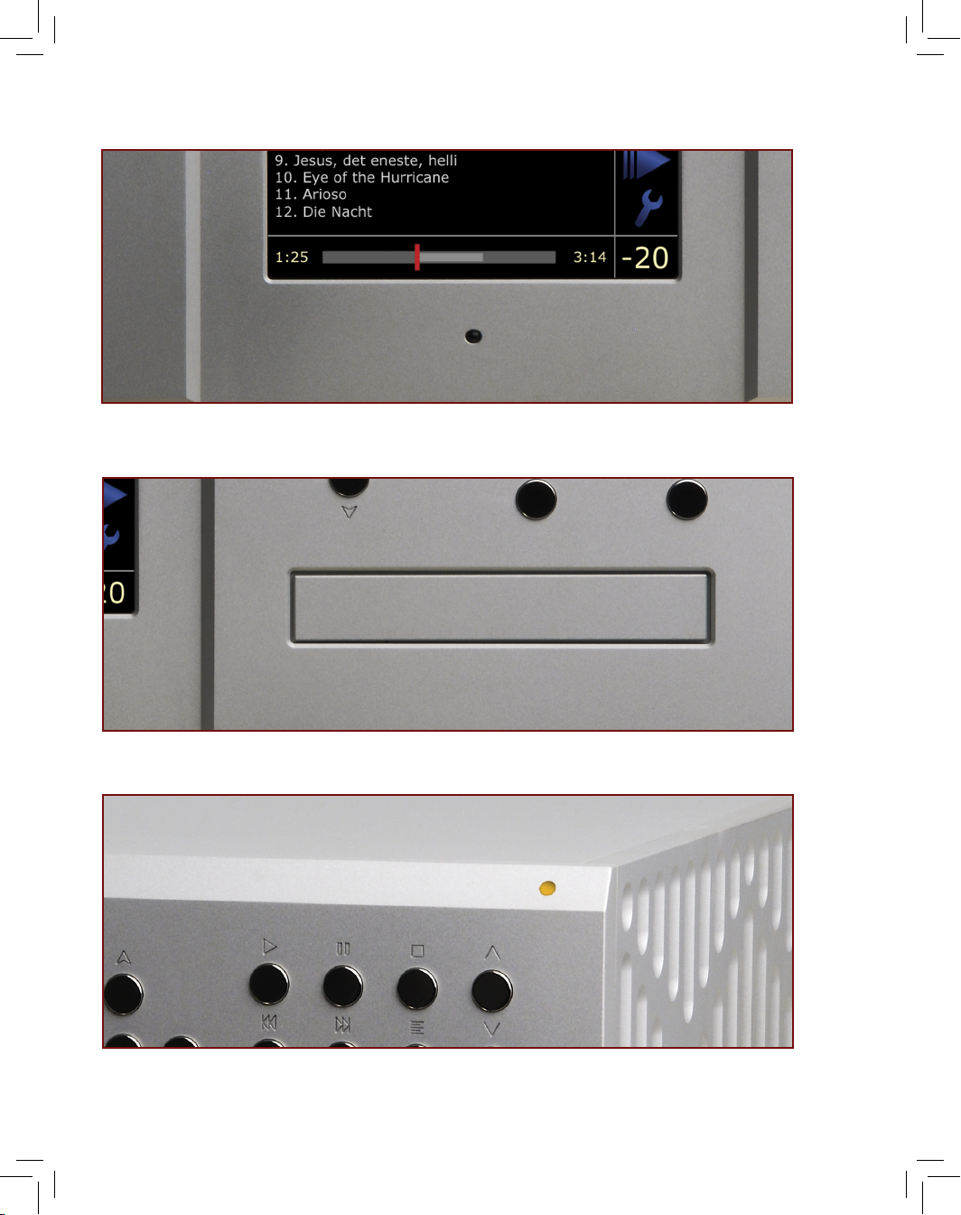
Infrared Remote Receiver.
The IR Remote Receiver is where your
1021 receives commands from the remote control. Do not cover or
block the IR Receiver.
Disc Tray.
The Disc Tray is where a disc is loaded into the 1021.
Status Indicator LED.
When the 1021 is in Standby mode, this LED
cycles from green to red to amber. When the 1021 is powering up, the
LED will alternately blink red and green rapidly. When the 1021 is active, it remains amber.
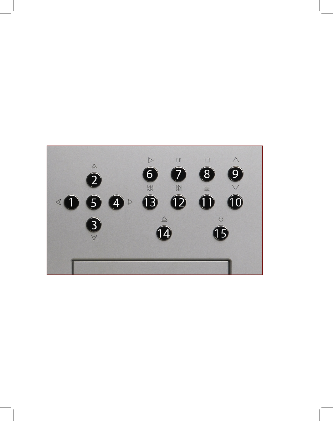
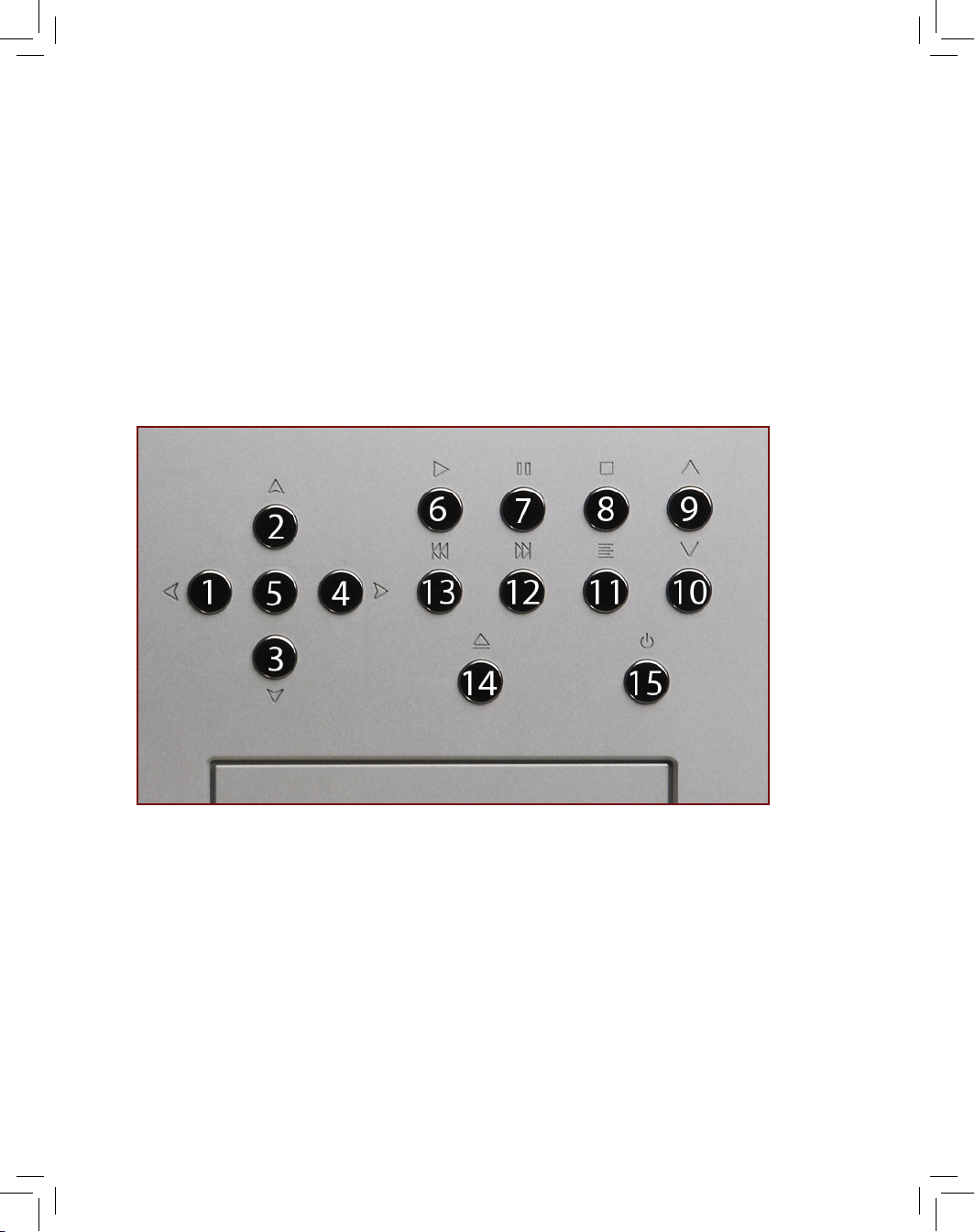
The Following user control buttons are present on the front panel:
Front Panel of the 1021
1021 Front
Panel
Page 22
6-5
Page 23

Navigate Left/Fast Reverse. 1.
This button is used to navigate
the menu system and to scan backward through tracks.
Navigate Up. 2.
This button is used to navigate the menu system.
Navigate Down. 3.
This button is used to navigate the menu
system.
Navigate Right/Fast Forward. 4.
This button is used to navigate
the menu system and to scan forward through tracks.
Enter. 5.
This button is used to make selections within the menu
system or to select tracks when creating a Play List.
Play. 6.
This button is used to begin playback of a disc inserted in
the 1021.
Pause. 7.
This button is used to pause music playback.
Stop. 8.
This button is used to stop music playback. When pressed
twice, this button will also clear any Play List programming and
reset the Track List
Volume Up. 9.
This button will raise the output level of the 1021 if
the volume option is set to “Variable.”
Volume Down. 10.
This button will lower the volume output level
of the 1021 if the volume option is set to “Variable.”
Options. 11.
This button engages the player’s Options list.
Skip Forward. 12.
This button advances playback to the next
track within the playlist.
Skip Back. 13.
This button moves playback to the beginning of
the current playing track or to the beginning of the previous
track if immediately pressed a second time.
Open/Close. 14.
This button opens and closes the disc drawer.
Front Panel of the 1021
1021 Front
Panel
Page 24
6-7
Page 25

6-8
S 15.
tandby.
This button toggles the 1021 between Active and
Standby modes.
Power Up or Active Mode
Front Panel of the 1021
1021 Front
Panel
Page 26

7-1
Page 27

7-2
Installation of the 1021 is simple and straightforward. Be sure all
cables to be connected to the 1021 are already in place. Note: as
the 1021 is very heavy, it is advisable to have two people install the
1021 to prevent damage.
Place the 1021 on the shelf or stand where it will be 1.
permanently installed. If the Player is going to be installed in
a cabinet or rack, please be aware that adequate ventilation
is necessary or damage to the player may occur. The 1021
should not be completely enclosed without some sort of
forced air ventilation.
If you will have access to the rear panel after placement, 2.
the 1021 should now be moved into its nal position. Be sure
that there is adequate ventilation for the rear panel heatsink
and the vents in the top cover. There should be at least 3.5”
of space on all sides if the 1021 is to be placed in a rack or
enclosure.
If you will not have access to the rear panel after placement, 3.
all interconnect and system cables should be connected
before moving the 1021 into its permanent location. Please
see Connecting the 1021 to Your System in the next section.
Installing the 1021
Installing
The 1021
Page 28
8-1
Page 29

8-2
The 1021 Disc Player is a very versatile machine and can be
connected to your audio/video system in a number of different ways.
To maximize the performance of your 1021 Disc Player, please follow
the appropriate instructions for your system and use.
All connections should always be made with the rear panel Master
AC Switch in the OFF position.
Connecting the 1021 to a Preamplier
To connect the 1021 to a preamplier, the volume control must rst
be set to “Fixed” in the menu system (see page 11-12). For optimum
performance, it is recommended that the 1021 be connected in an
all-balanced, 3-pin XLR system.
Connect the Left channel interconnect cable (usually white) to
one of the Left channel output connectors of the 1021. As both
connectors are the same, it does not matter which left channel
connector is used. The other end of the cable should be connected
to the left channel preamplier input.
Connect the Right channel interconnect cable (usually red) to
one of the Right channel output connectors of the 1021. As both
connectors are the same, it does not matter which right channel
connector is used. The other end of the cable should be connected
to the right channel preamplier input.
Connecting the 1021 Directly to a Power Amplier
When the internal volume control is activated, the 1021 is capable of
driving the inputs of a power amplier directly.
To connect the 1021 directly to a power amplier (without the use of
a preamplier), the volume control must rst be set to “Variable” in
the menu system (see page 11-12). For optimum performance, it is
recommended that the 1021 be connected in an all-balanced, 3-pin
XLR system.
Connecting the 1021 to Your System
Connecting
The 1021
Page 30

8-3
Page 31

8-4
Note: the volume control MUST be set to Variable mode or possible
system damage may occur!
Connect the Left channel interconnect cable (usually white) to
one of the Left channel output connectors of the 1021. As both
connectors are the same, it does not matter which left channel
connector is used. The other end of the cable should be connected
to the left channel amplier input.
Connect the Right channel interconnect cable (usually red) to
one of the Right channel output connectors of the 1021. As both
connectors are the same, it does not matter which right channel
connector is used. The other end of the cable should be connected
to the right channel amplier input.
Connecting a Second Set of Outputs
The 1021 is outtted with two pairs of output connectors to drive secondary ampliers, recorders, or subwoofers. Both pairs of outputs will
operate in tandem and cannot be controlled independently, whether
the volume control is in Fixed or Variable mode.
Connect the Left channel interconnect cable (usually white) to the
remaining Left channel output connector of the 1021. The other end
of the cable should be connected to the left channel input of the
component you are connecting.
Connect the Right channel interconnect cable (usually red) to the
remaining Right channel output connector of the 1021. The other
end of the cable should be connected to the right channel input of
the component you are connecting.
Connecting the 1021 with Unbalanced Connections
It is strongly recommended that the 1021 be connected with
balanced connections wherever possible in order to enjoy the
true performance for which it was designed. If it is not possible to
use balanced connections, it is still possible to connect the 1021.
There are two methods of connecting the 1021 with unbalanced
connections:
Connecting the 1021 to Your System
Connecting
The 1021
Page 32

8-5
Page 33

8-6
Special Boulder balanced-to-unbalanced adaptors (model: 1.
ABL) are available. Please contact your Boulder dealer to
purchase adaptors.
Interconnect cables can be re-terminated with an 2.
unbalanced connection on one end. Please contact your
cable dealer for more information regarding this method.
Connecting the IR Input
If the 1021 will not be located where the handheld remote control
can be used, an external infrared receiver can be placed in a
remote location to route the remote signals to the rear panel IR Input
1/8” mini-jack. The 1021 can also be controlled by external control
and automation software common in large or custom installations.
The IR Input is compatible with all common control systems. For more
information regarding this connection and method of control, please
contact your Boulder dealer.
Connecting an Amplier to the 12V Trigger
A 12V remote ON/OFF 1/8” mini-jack connector is provided on the
rear panel of the 1021 for remotely switching ampliers ON and OFF
if they have a proper companion connector. Please contact your
Boulder dealer for further information about this feature.
Connecting to the Ethernet
The 1021 Disc Player is capable of direct connection to the Ethernet
so that it can download and display any available artist, album, and
track list information for discs that do not already contain metadata
or CD Text. In order to do so, the 1021 must be connected via CAT-5
(or better) data cable to a computer network with an active Internet
connection.
Place the 1021 in Standby Mode via the front panel Standby button
and connect the player to your computer network. When the 1021
is then switched to Active mode via the front panel Standby button,
it will automatically connect to the Internet. No address assignments
are necessary.
Connecting the 1021 to Your System
Connecting
The 1021
Page 34

8-7
Page 35

8-8
Connecting an External Display
The 1021 Disc Player has a large, 6.5” display that is easy to read from a
distance. The 1021 is also capable of driving an external display device (such as a computer or video monitor or projector).
To use the external display feature of the 1021, the monitor or projector must have a VGA input connection. All graphic information will be
sent at the native resolution of the 1021 Disc Player (640 x 480). Please
contact your Boulder dealer for further information regarding the
External Display connection to your computer, video monitor, or home
theater video display system.
Connecting the 1021 to AC Mains
Once all of the necessary rear panel connections have been
properly secured, the 1021 can then be connected to AC mains
and powered up. The 1021 Disc Player uses a standard 3-pin 15A
IEC power connector. Install the provided power cable to the AC
mains power connector on the rear panel. The unit can then be
connected to your AC mains wall outlet and the Master AC Switch
moved to the ON position. The front panel Status Indicator LED
should now be illuminated.
Connecting the 1021 to Your System
Connecting
The 1021
Page 36
9-1
Page 37

9-2
A hand-held infrared remote control is included with the 1021. This
remote control is machined out of aerospace-grade aluminum and
is heavy. Please be careful not to drop the remote on furniture or
ooring.
If you notice that your remote control seems not to be working
properly, the batteries are probably low. Check the batteries
periodically and replace them before they are “dead.” Fully
discharged batteries are prone to leaking and may cause damage
to the remote control.
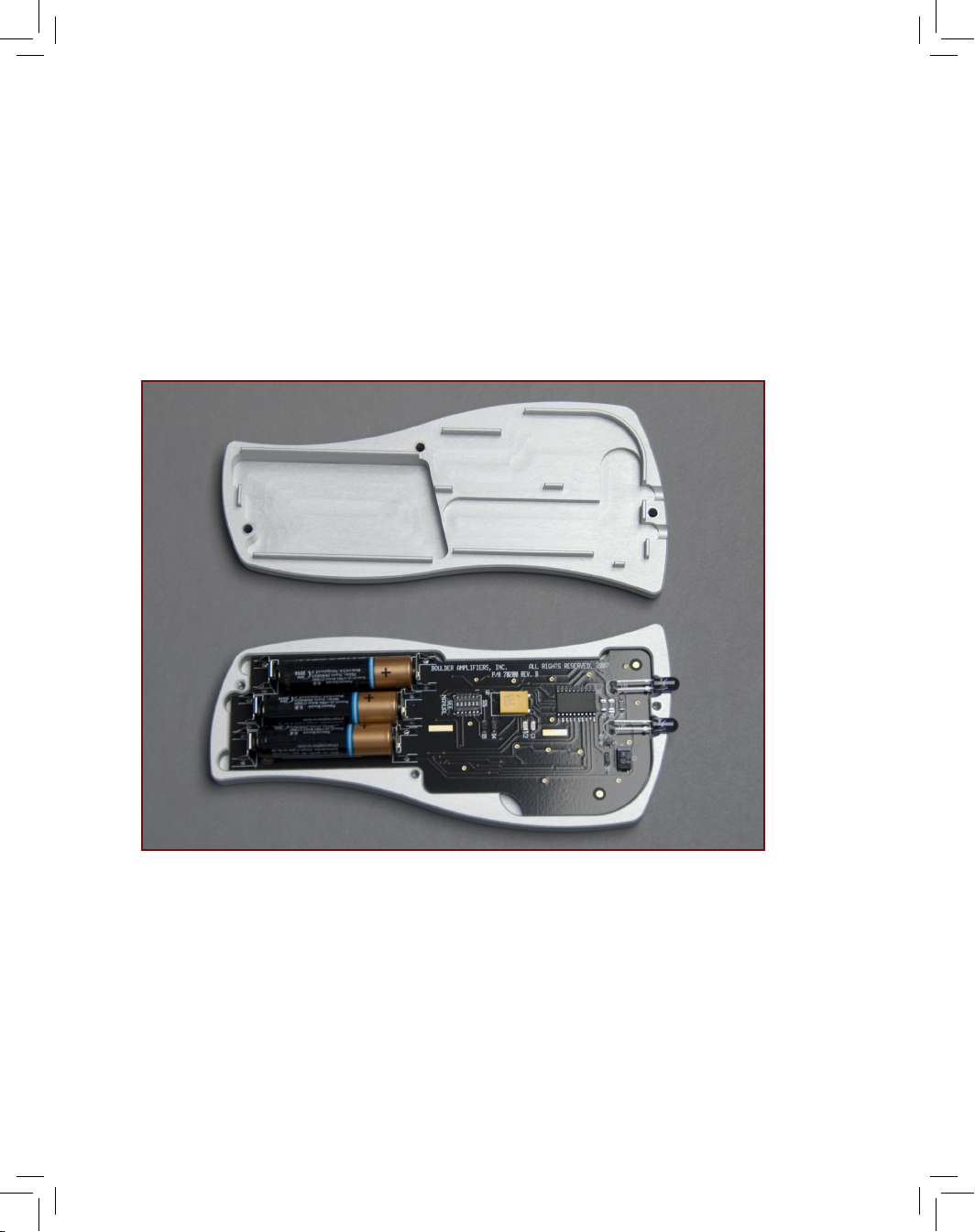
Installing the Batteries in the Remote Control
The 1021 Remote Control is powered by three (3) AAA batteries. To
install or replace batteries in the remote control, it is necessary to
separate the two halves of the remote housing.
Note: When opened, the remote’s pushbutton balls will not be held
securely in place and care must be taken so that they are not lost!
Laying the remote control 1. face down on a at surface so that
the balls will stay in position is strongly recommended.
Using a #3 at-blade screwdriver, remove the three (3) screws 2.
that secure the rear panel of the remote control.
Install the three (3) batteries with the positive (+) terminals 3.
facing as indicated on the battery holder.
Replace the cover and reinstall the three (3) screws. 4.
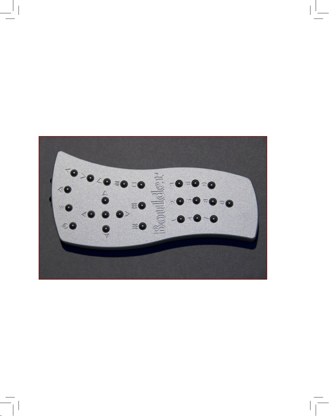
The remote of the 1021 features all of the commands necessary to
operate any function of the 1021. The following commands are
included on the remote. Unless otherwise noted, the Remote Control
operates exactly the same as the Front Panel Buttons.
Remote Control
Remote
Control
Page 38
9-3
Page 39

9-4
Remote Control Buttons
Standby. 1.
Options. 2.
Open/Close. 3.
Navigate Up. 4.
Navigate Right/Fast Forward. 5.
Navigate Down. 6.
Navigate Left/Fast Reverse. 7.
Enter. 8.
Volume Up. 9.
Volume Down. 10.
Play. 11.
Pause. 12.
Skip Back. 13.
Skip Forward. 14.
Stop. 15.
Numeric Keypad. 16. The Numeric Keypad includes buttons
numbered 0 – 9 and allows you to access any track on the
disc directly.
For example, to access track 3, press the number 3 on the
Numeric Keypad and then press Play. The player will instantly
begin to play track 3. If the number 3 on the numeric keypad
is pressed and the Play button is not pressed, the player will
automatically begin to play track 3 after a period of two (2)
seconds. Any track number can be entered via the numeric
keypad up to 999, assuming there are that many tracks on the
disc.
Remote Control
Remote
Control
Page 40

10-1
Page 41

10-2
To bring the player out of Standby mode, press the Standby button on
the front panel or the remote. The player will go through its power up
sequence for a few seconds and will then be ready for operation.
Playing a Disc
Although it features a large number of playback options, the 1021 is
a very simple machine to use. The 1021 operates like a traditional CD
player, so it is not necessary to go through all of the menu options or
setup tools before playing music.
With the 1021 in Active mode, press the Open/Close button to open
the disc drawer. Place a disc in the tray label side up and press Play.
The disc will begin playing.
To advance to the next track while a disc is playing, press •
the Skip Forward button. Pressing the button repeatedly will
make the player continue to skip forward through tracks.
To go back to the previous track while a disc is playing, press •
the Skip Back button twice. Pressing the button repeatedly
will make the player continue to skip backward through
tracks.
To fast forward while a disc is playing, press the • Navigate
Right button. Pressing the button multiple times will increase
the speed at which the 1021 scans through the disc.
Pressing the Navigate Left button will reduce the rate at
which the 1021 scans through the disc. Pressing Play will stop
the Fast Forward function.
To fast reverse while a disc is playing, press the • Navigate Left
button. Pressing the button multiple times will increase the
speed at which the 1021 scans through the disc. Pressing
the Navigate Right button will reduce the rate at which the
1021 scans through the disc. Pressing Play will stop the Fast
Reverse function.
To temporarily pause playback, press the • Pause button.
Basic Operation
Basic
Operation
Page 42

10-3
Page 43

10-4
Pressing the button a second time or pressing Play will make
the player resume playback. If the player is left in Pause
mode for too long, it will automatically stop playback to
preserve the disc mechanism.
To cancel playback, press the • Stop button.
Basic Operation
Basic
Operation
Page 44

11-1
Page 45

11-2
The 1021 includes a number of features that are not available in
any other disc player. The following is a list of the more advanced
playback features.
Direct Track Access. 1.
To select and play a track directly, use the Numeric Keypad
on the remote control and type in the number of the track
you wish to play, then press the Play button on the remote
control (if you do not press Play, the player will automatically
begin playing that track after two (2) seconds).
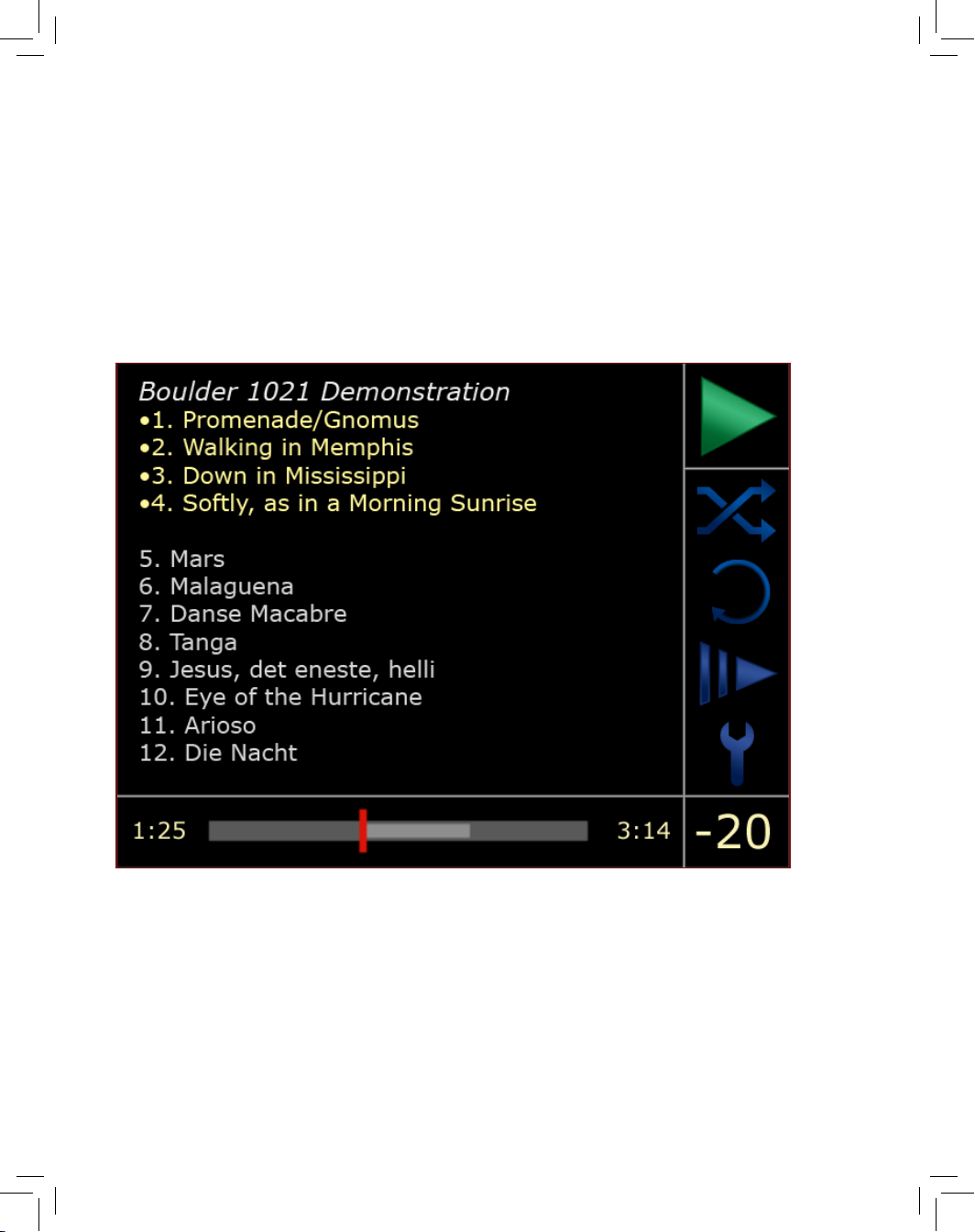
Navigating the Track Listing. 2.
It is possible to navigate through the Track List to select a
track directly or to view all of the available tracks. This can
be done while the disc is playing or while the disc is stopped.
With a disc in the player (playing or not), press the • Navigate
Up or Navigate Down button to scroll through the Track List.
The text for the track that is cued or playing will be green.
The text for the tracks that you are scrolling through will be
pale yellow. As you scroll through the tracks, the size of the
text for each highlighted track will increase so that it can be
read from a distance.
When you locate the track you wish to play, press the • Play
button. The highlighted track will begin playing immediately.
If you stop navigating through the Track List, the player will •
resume normal playback status ve seconds after the last
button is pressed. The enlarged text will once again revert to
the green track that is cued or playing.
Advanced Operation
Advanced
Operation
Page 46
11-3
Page 47

11-4
Creating a Playlist
You can create a Playlist for any disc for selecting and ordering the
tracks to be played. In this mode, only tracks in the programmed
playlist will be played. The 1021 will remember programmed playlists
and will play the last programmed playlist when that disc is inserted at
a later date (unless cancelled by pressing the Stop button twice while
that disc is in the machine). It is possible to program a playlist with either the remote control or the front panel buttons.
To program a playlist into the 1021, use the following sequence:
Insert a disc but do not press play. Allow the player to read 1.
the disc and display a track listing.
Using the 2. Navigate Up or Navigate Down button, scroll to a
track that you would like to add to a playlist.
Press the 3. Enter button. The track has now been “tagged” and
moved to the top of the Track List. A small dot or circle should
also be located to the left of the track name to indicate that it
has been programmed.
Locate and select as many tracks as you would like to add to 4.
the playlist. They will be added in the order you select them.
The tracks that have not been selected will remain at the
bottom of the track listing.
Press 5. Play. The 1021will play the tracks in your programmed
playlist in the order that you selected them. Playback will stop
when the last track in your playlist has ended.
To clear or erase the playlist, press the 6. Stop button twice
while the disc is still in the 1021. If the disc is ejected and
removed before the Stop button is pressed twice, the 1021 will
remember your programmed playlist. The next time that CD is
inserted in the 1021, it will load and play only the programmed
playlist unless the Stop button is pressed twice.
Advanced Operation
Advanced
Operation
Page 48
11-5
Page 49

11-6
Options
The right-hand side of the display includes a number of Options icons
that allow you to customize playback to your preferences. The Options icons include Random Playback, Repeat, Scan, and Setup Tools.
To navigate to the Options list, use the following sequence:
On the remote control or front panel, press the 1. Options button.
One of the Options icons should now be highlighted in pale
yellow.
Pressing the 2. Navigate Up or Navigate Down button on the
remote control will now move the highlighting up or down the
Options list.
To select a particular Option, press the 3. Enter button when the
Option you wish to select is highlighted. The selected icon will
then turn green.
To exit the Options list, press the 4. Options button again.
The following Options are available:
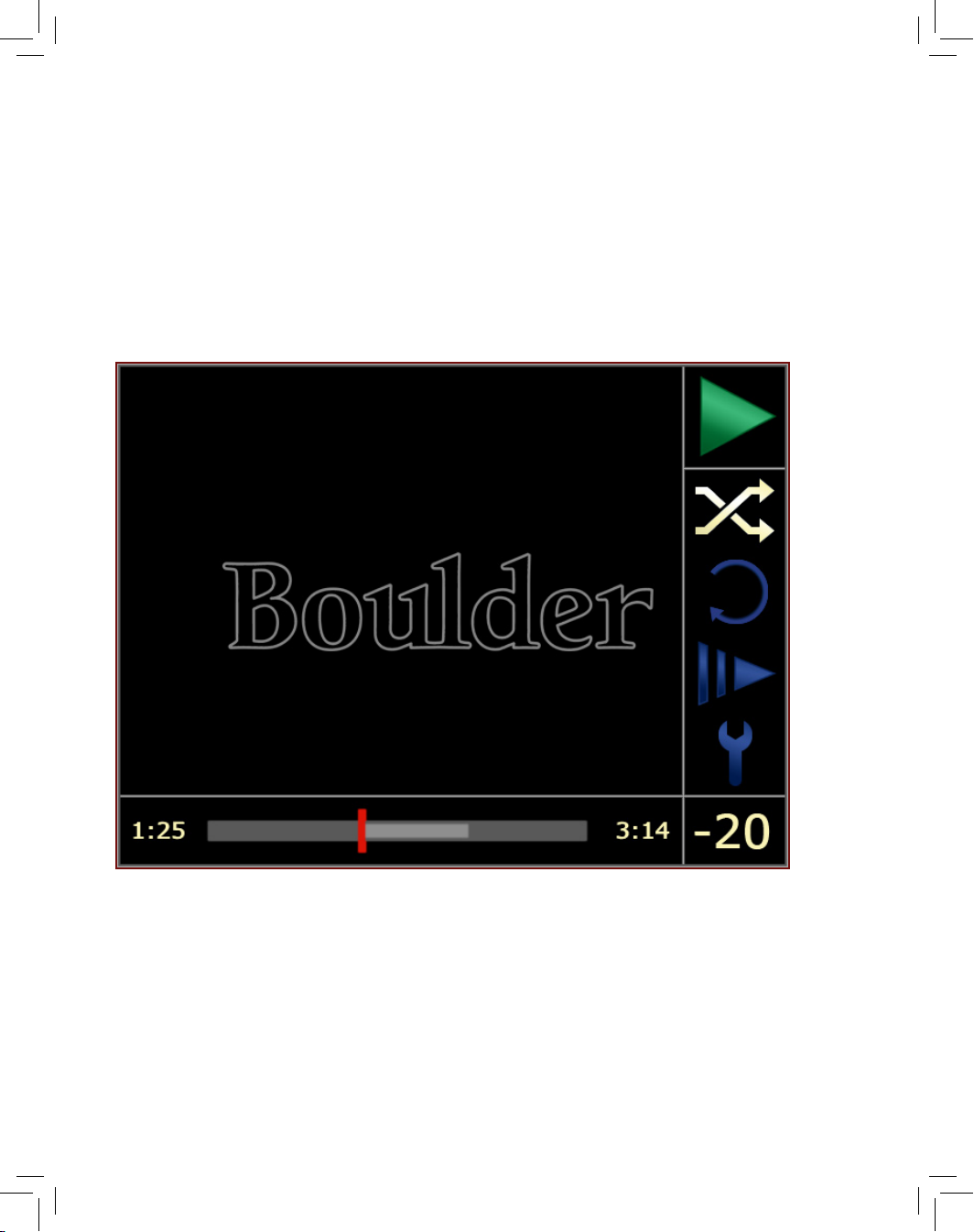
Random Play
When activated, the Random Play option will allow the 1021 to play
tracks from the entire disc or a programmed Playlist in randomized
order.
To activate Random Play, enter the Options list and move the
highlighting to the Random Play icon. Press the Enter button. The
Random Play icon should then turn green. Once the Play button
is pressed, the 1021 will then play all tracks from the disc (or the
tracks that have been programmed if a Playlist has been entered) in
random order.
Advanced Operation
Advanced
Operation
Page 50
11-7
Page 51

11-8
Repeat Play
When activated, the Repeat Play options will allow the 1021 to repeat
the entire disc, one track of the disc, or a selected portion of the disc
(A-B).
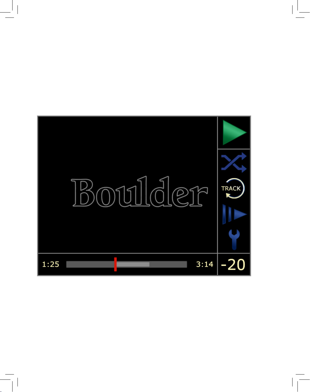
To activate Repeat Play, enter the Options list and move the
highlighting to the Repeat Play icon. Select the mode of Repeat Play
you wish to use by using the Navigate Left or Navigate Right button.
The mode of Repeat Play will appear within the circular arrow icon.
Pressing the Enter button will turn the icon green and activate Repeat
Play.
To deactivate Repeat Play mode, press the Stop button twice.
The three modes of Repeat Play are listed below:
Repeat Track:
When selected, the 1021 will continually repeat
the track that is presently playing. Playback will not stop until
Repeat Play is deactivated or the Stop button is pressed.
Repeat Disc:
When selected, the 1021 will continually repeat
playback of the entire disc when it reaches the end of the last
track. If a Playlist has been programmed, only the selected
tracks will be repeated. Playback will not stop until Repeat Play
is deactivated or the Stop button is pressed.
Repeat A-B:
When selected, the 1021 will repeat playback of
only a selected portion of a disc. To mark the beginning of the
repeated portion of the track, select Repeat A-B in the Options
List while the desired track is playing. At the point where you
would like to have the repeated section of the track begin,
press the Enter button. The beginning of your selection will be
marked by a green “A” on the Progress Bar. At the point where
you would like to have the repeated section of the track end,
press the Enter button again. The end of the selection will be
marked by a red “B” on the Progress Bar. The 1021 will now
continuously repeat the portion of the disc between the programmed “A” and “B” markers. Repeat A-B Play will not stop
until Repeat Play is deactivated or the Stop button is pressed.
Advanced Operation
Advanced
Operation
Page 52
11-9
Page 53

11-10
Disc Scan Playback
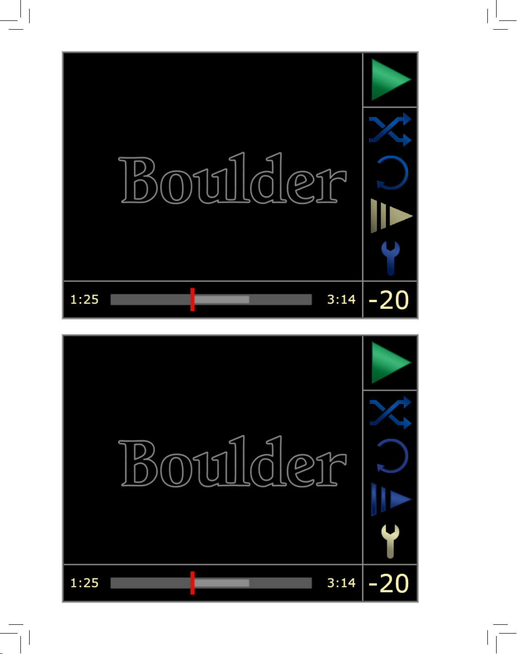
When activated, the Disc Scan Playback option will allow the 1021
to play only the introduction of each track. This is helpful in locating
a track when you do not know the name of the track or track name
information is not available and you do not wish to skip through each
track manually.
To activate Disc Scan Playback, enter the Options list and move the
highlighting to the Disc Scan Playback icon. Press the Enter button.
The Disc Scan Playback icon should then turn green. The 1021 will be-
gin playing the rst few seconds of each track (for instructions to program the length of each track that the 1021 will play, please see page
2-14). Press the Options button. Once the desired track has been
located or to turn the Disc Scan Function off, press the Play button.
Setup Tools
The Setup option allows you to program a number of personal preferences into the 1021.
To access the Setup menus, enter the Options list and move the
highlighting to the Setup Tools icon and press the Enter button. The
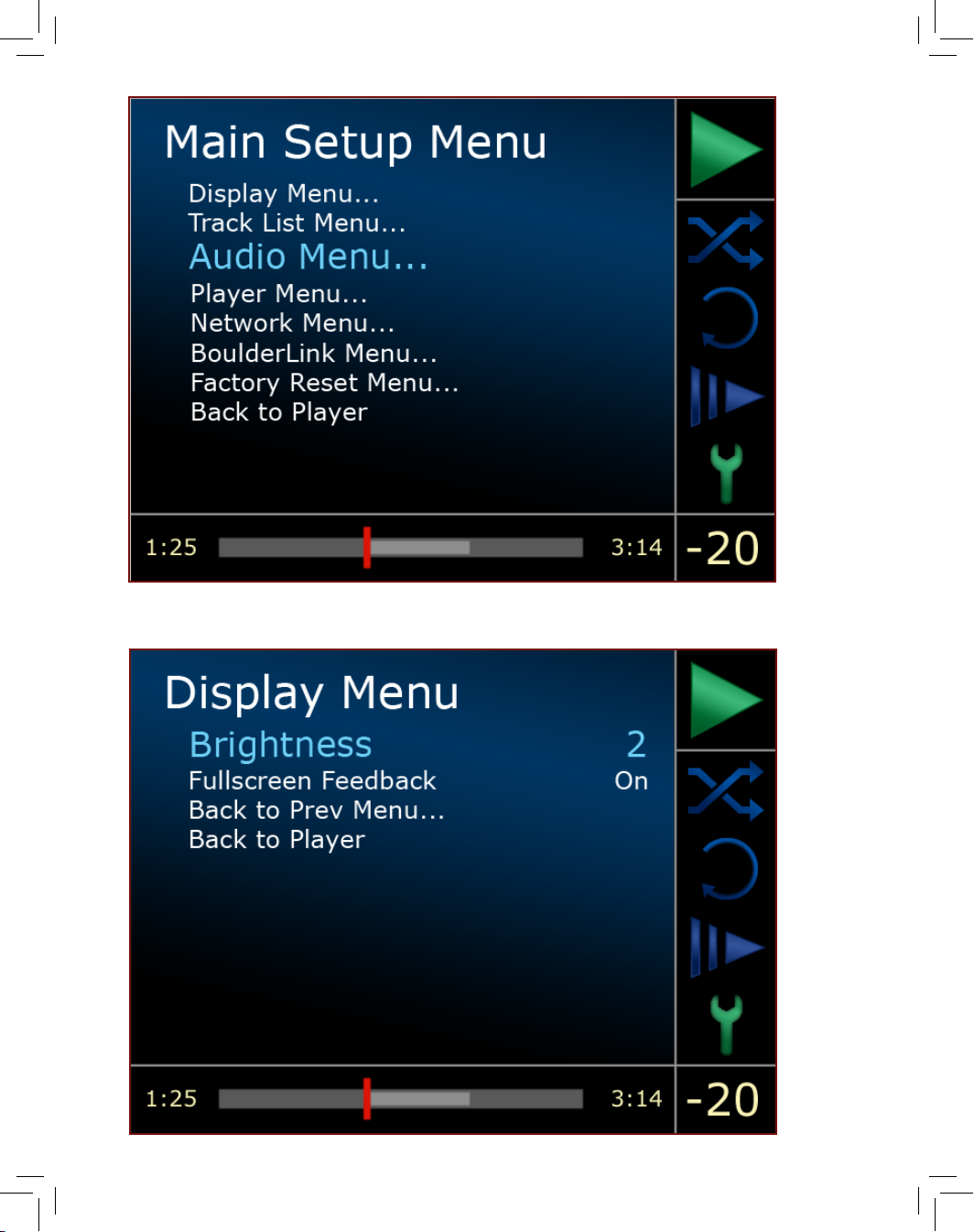
display will now show the Main Setup Menu, which includes the
Display Menu, Audio Menu, Track List Menu, Player Menu, Network
Menu, Boulder Link Menu, Factory Reset Menu, and Back to Player.
Main Setup Menu
You can customize the 1021 by programming a number of user
options and preferences in the Setup menus. While these options do
not have to be programmed in order to enjoy the use of the 1021,
additional programming may enhance your experience with the
player. The following pages will instruct you on the function of each
option as well as how to program it.
To enter the Main Setup Menu, enter the Options list and move the
highlighting to the Setup Tools icon and press the Enter button. The
Advanced Operation
Advanced
Operation
Page 54
12-1
Page 55

12-2
display will now show the Main Setup Menu, which includes the
Display Menu, Track List Menu, Audio Menu, Player Menu, Network
Menu, Boulder Link Menu, Factory Reset Menu, and Back to Player.
To select one of the submenus in the Main Setup Menu, use the
Navigate Up or Navigate Down button to move the highlighted
selection up or down the list. The highlighted item will turn blue
and the text will enlarge. When you have highlighted the desired
submenu, press the Enter button.
The following submenu options are available:
Display Menu
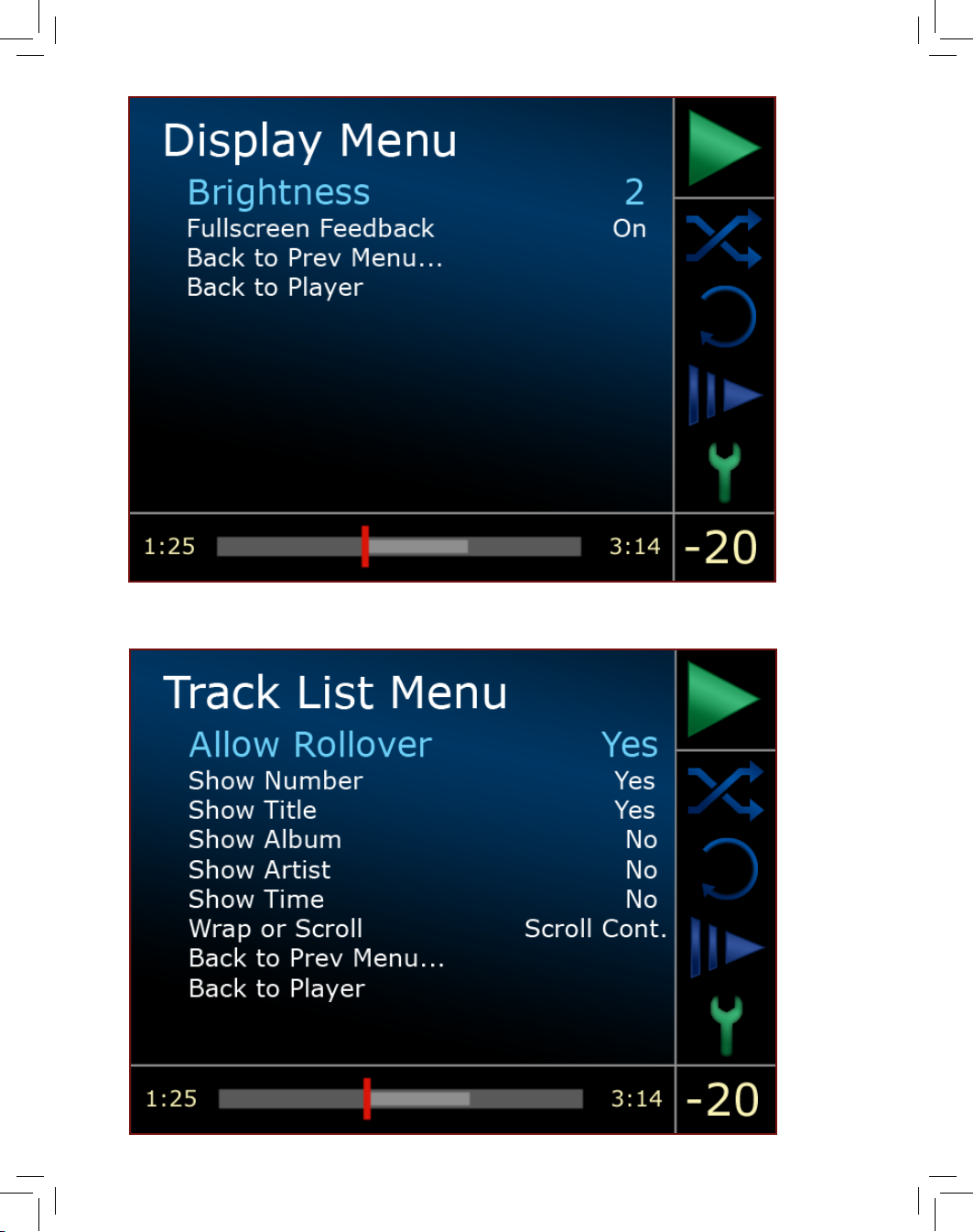
The Display Menu allows you to adjust the functions and settings that
affect the display of the 1021. To navigate the Display Menu, use the
Navigate Up or Navigate Down button and then press Enter once the
desired option is highlighted. The following options are available in
the Display Menu:
Brightness
There are nine levels of intensity for the brightness of display,
MAX (Maximum), 7, 6, 5, 4, 3, 2, 1, and Off.
To adjust the brightness of the display, use the Navigate Left
or Navigate Right button to change the level of intensity.
If Off is selected, the display will dim to its lowest setting,
however the display will not turn off until the menu system is
exited. If Off is selected, the display will also re-illuminate for
three seconds each time a button is pressed.
Fullscreen Feedback
If Fullscreen Feedback is activated, the display will show a
full-screen sized Status icon for a few moments to indicate
that a button on the remote control has been pressed.
Fullscreen Feedback is only activated by the remote control
buttons and is not activated by the front panel buttons.
Setup and Programming
Setup &
Programing
Page 56
12-3
Page 57

12-4
To set the Fullscreen Feedback mode, use the Navigate Left
or Navigate Right button to turn the system On or Off.
Back to Prev Menu
Pressing the Enter button while Back to Prev Menu is
highlighted will take you back to the Main Setup Menu.
Back to Player
Pressing the Enter button while Back to Player is highlighted
will exit the menu system and take you back to the Track List
display.
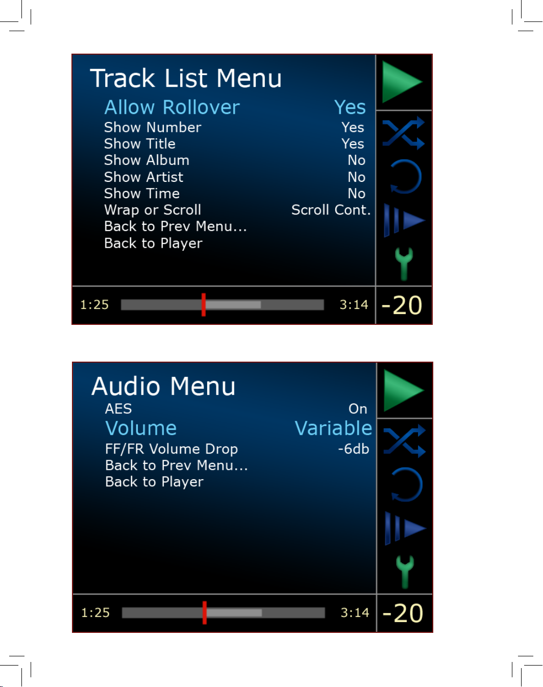
Track List Menu
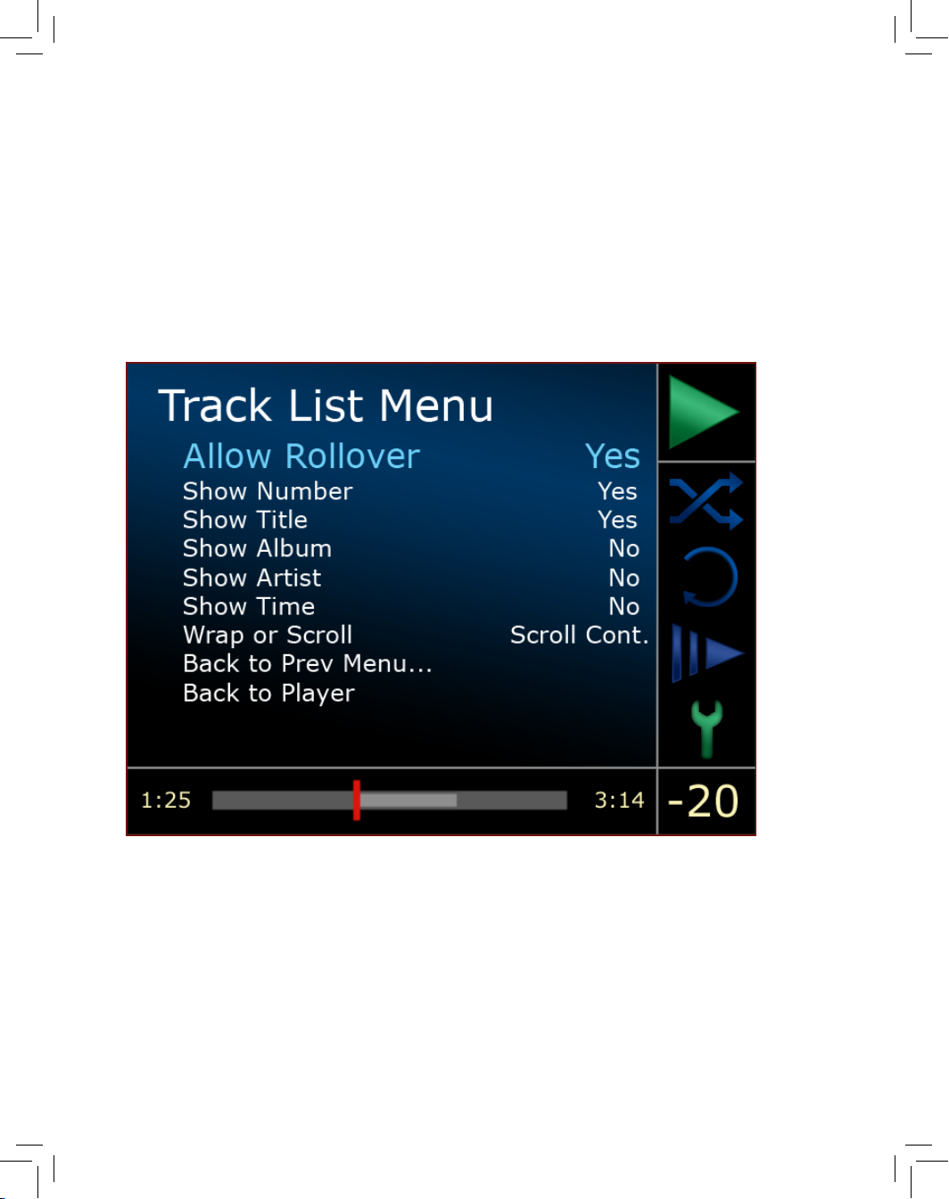
The Track List Menu allows you to adjust the way the Track List display
functions. To navigate the Track List Menu, use the Navigate Up or
Navigate Down button and then press Enter once the desired option
is highlighted. The following options are available in the Track List
Menu:
Allow Rollover
The Allow Rollover option turns the ability to scroll through the
last track in the Track List and back to the rst (or vice-versa)
On or Off.
For example, if Allow Rollover is turned On, when scrolling
through the Track List using the Navigate Down button, the
highlighted track will return to the top of the Track List when
the last track is passed. When scrolling through the Track List
using the Navigate Up button, the highlighted track will return
to the bottom of the Track List when the rst track is passed.
If Allow Rollover is turned Off, the highlighted track will simply
stop scrolling once the beginning or end of the Track List is
reached.
To adjust the Allow Rollover setting, use the Navigate Left or
Navigate Right button to toggle the system between On and
Setup and Programming
Setup &
Programing
Page 58
12-5
Page 59

12-6
Off.
Show Number
The Show Number option turns the track number indication
on the left-hand side of the Track List display On or Off.
Turning the track numbers off increases the amount of space
available for track names, however it may be desirable for
the track numbers to be displayed if longer MP3 discs are
being played.
To adjust the Show Number setting, use the Navigate Left or
Navigate Right button to toggle the system between On and
Off.
Show Title
The Show Title option turns the track title indication in the
Track List display On or Off. This may be preferable if the
discs that are being played have no metadata or track
information is not available to be displayed.
To adjust the Show Title setting, use the Navigate Left or
Navigate Right button to toggle the system between On and
Off.
Show Album
The Show Album option turns the album title indication in the
Track List display On or Off. This option will show the album
title in each track listing. It may be preferable to turn this
feature on if compilation CD-Rs are played or if discs with a
large number of MP3 tracks are played.
To adjust the Show Album setting, use the Navigate Left or
Navigate Right button to toggle the system between On and
Off.
Setup and Programming
Setup &
Programing
Page 60
12-7
Page 61

12-8
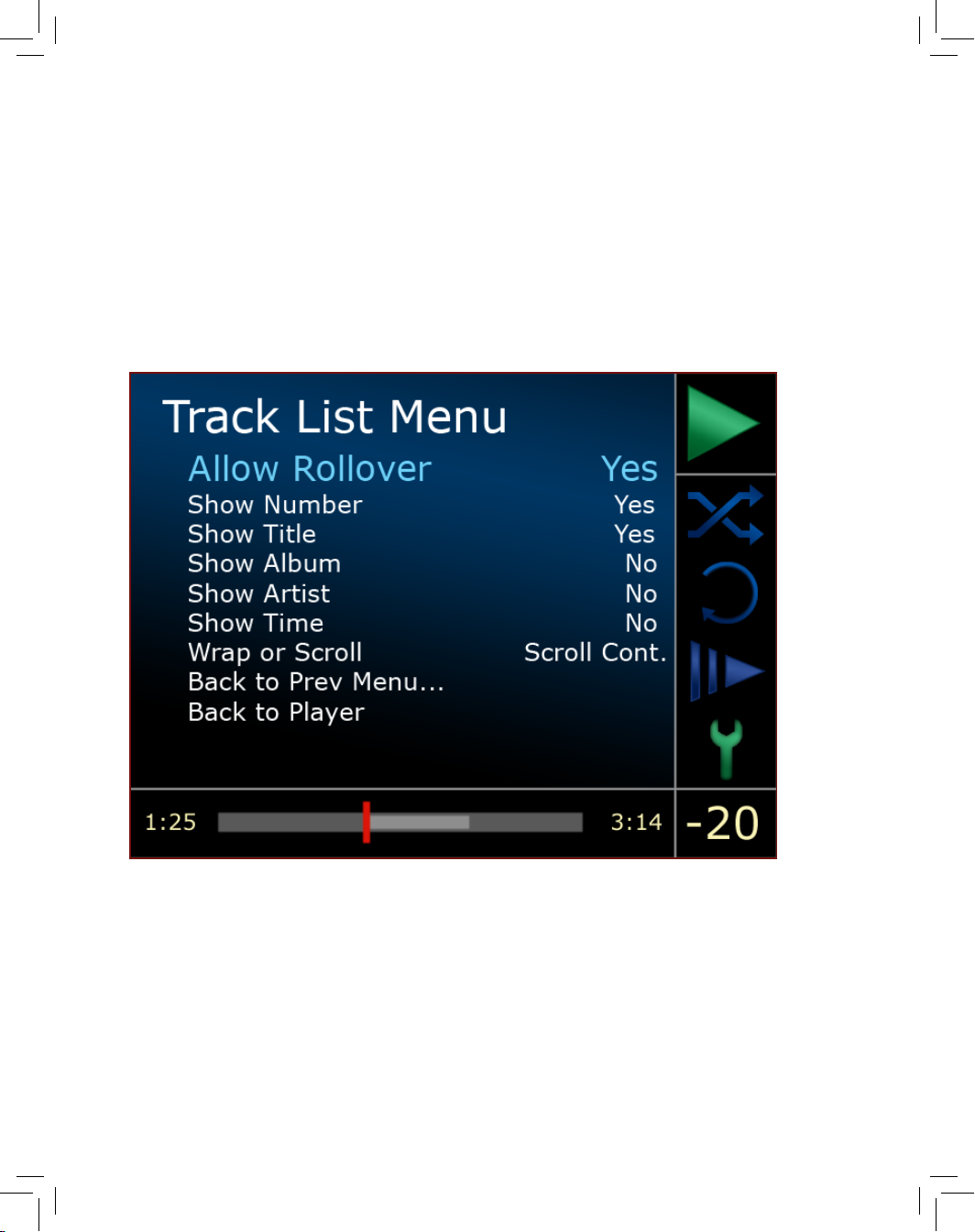
Show Artist
The Show Artist option turns the artist name indication in the
Track List display On or Off. This option will show the artist
name in each track listing. It may be preferable to turn this
feature on if compilation discs are played or if discs with a
large number of MP3 tracks are played.
To adjust the Show Artist setting, use the Navigate Left or
Navigate Right button to toggle the system between On and
Off.
Show Time
The Show Time option turns the track time indication on the
right-hand side of the Track List display On or Off. This option
shows the total duration of each track.
To adjust the Show Time setting, use the Navigate Left or
Navigate Right button to toggle the system between On and
Off.
Wrap or Scroll
The Wrap or Scroll option determines how each track title is
displayed.
When this option is set to Wrap, the track title will wrap around
to a second line of text if the track title is longer than one line.
If the title is longer than two lines, the track title will simply be
truncated.
When this option is set to Scroll Once, the track title will scroll
across the display in a single line until the entire track title has
been shown. After scrolling, it will then truncate to a single
line of text.
When this option is set to Scroll Cont., the complete track title
will scroll continuously across the display in a single line of text.
Setup and Programming
Setup &
Programing
Page 62
12-9
Page 63

12-10
To set the Wrap or Scroll mode, use the Navigate Left or
Navigate Right button to select Wrap, Scroll Once, or Scroll
Cont.
Back to Prev Menu
Pressing the Enter button while Back to Prev Menu is
highlighted will take you back to the Main Setup Menu.
Back to Player
Pressing the Enter button while Back to Player is highlighted
will exit the menu system and take you back to the Track List
display.
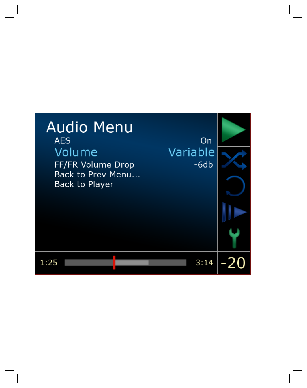
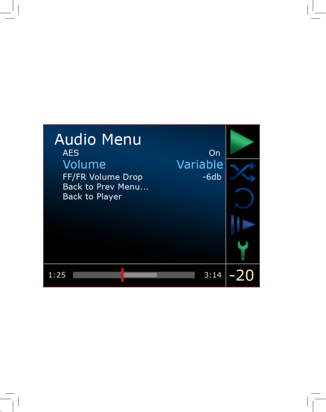
Audio Menu
The Audio Menu allows you to adjust the functions and settings that
affect the audio outputs of the 1021. To navigate the Audio Menu,
use the Navigate Up or Navigate Down button and then press Enter
once the desired option is highlighted. The following options are
available in the Audio Menu:
AES
The AES option activates or deactivates the AES digital output
connection on the rear panel of the 1021.
To set the AES mode, use the Navigate Left or Navigate Right
button to turn the system On or Off.
Volume
The Volume option enables or disables the 1021’s internal
volume control.
If the 1021 is to be connected to a preamplier, the volume
control mode should be set to Fixed. If the volume control is
set to Fixed, the output of the 1021 cannot be adjusted.
Setup and Programming
Setup &
Programing
Page 64
12-11
Page 65

12-12
If the 1021 will be connected directly to an amplier, the
volume control mode should be set to Variable.
Note: If the 1021 will be connected directly to an amplier,
do NOT set the volume control mode to Fixed. This will
result in maximum output and may lead to damage to your
loudspeakers. If the Volume setting is changed to Fixed,
the player will automatically set itself to the Pause playback
mode to prevent the full-scale output level from damaging
your system if the 1021 is playing.
To set the Volume mode, use the Navigate Left or Navigate
Right button to toggle the system between Fixed or Variable
modes.
FF/FR Volume Drop
It is possible to program the 1021 to attenuate the output
a specic amount when the Fast Forward and Fast Reverse
functions are activated. The level of attenuation can be
adjusted to -12 dB, -11 dB, -10 dB, -9 dB, -8 dB, -7 dB, -6 dB, -5
dB, -4 dB, -3 dB, -2 dB, -1 dB or Off (no attenuation).
To adjust the FF/FR Volume Drop, use the Navigate Left
or Navigate Right button to select the specic level of
attenuation you prefer.
Back to Prev Menu
Pressing the Enter button while Back to Prev Menu is
highlighted will take you back to the Main Setup Menu.
Back to Player
Pressing the Enter button while Back to Player is highlighted
will exit the menu system and take you back to the Track List
display.
Setup and Programming
Setup &
Programing
Page 66
12-13
Page 67

12-14
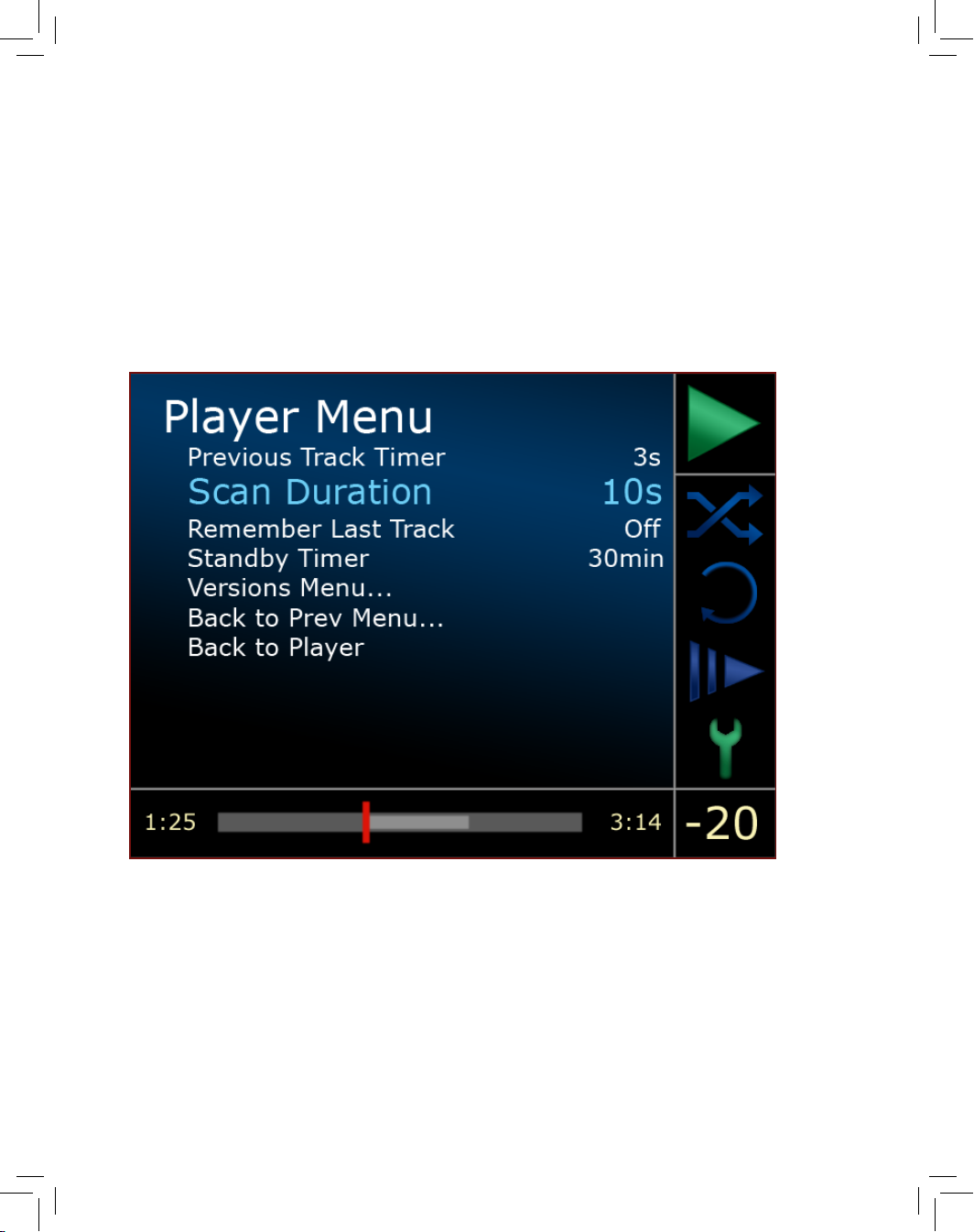
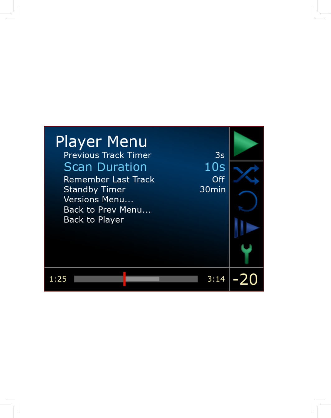
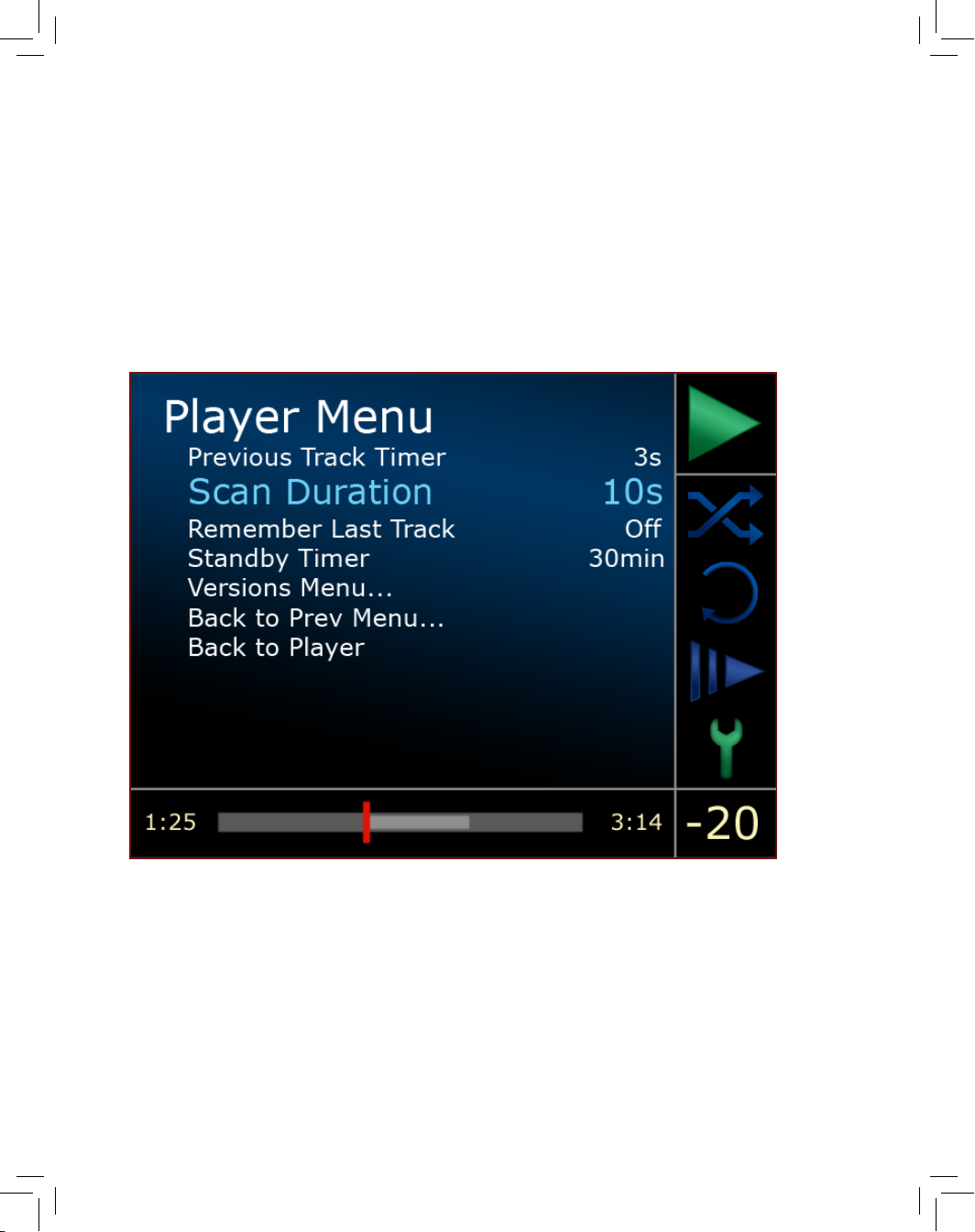
Player Menu
The Player Menu is used to view or adjust functions related to basic
player functions. To navigate the Player Menu, use the Navigate Up or
Navigate Down button and then press Enter once the desired option is
highlighted. The following options are available in the Player Menu:
Previous Track Timer
The Previous Track Timer option determines the length of
time in which a second press of the Skip Back button will skip
past the start of the track that is currently playing and to the
beginning of the previous track.
For example, the default setting is three seconds (3s). If you
wish to skip to the song prior to the track that is currently
playing, you must press the Skip Back button twice within
three seconds. If the Previous Track Timer is set for one
second (1s), you must press the Skip Back button twice within
one second in order to skip to the previous track.
The Previous Track Timer can be set in one-second increments
of 1s, 2s, 3s, 4s, 5s, 6s, 7s, 8s, 9s or 10s.
To adjust the Previous Track Timer, use the Navigate Left or
Navigate Right button to select the specic length of time
you prefer.
Scan Duration
The Scan Duration option determines the length of time in
seconds that the 1021 will play the introduction of each track
before moving on to the next track when the 1021 is placed
in Scan mode.
The length of time can be set to 2s, 5s, 10s, 20s or 60s.
To adjust the Scan Duration timer, use the Navigate Left or
Navigate Right button to select the specic length of time
you prefer.
Setup and Programming
Setup &
Programing
Page 68
12-15
Page 69

12-16
Remember Last Track
The Remember Last Track option enables the 1021 to
remember which track was playing when the disc was last
stopped and ejected before it had played through the entire
Track List. If enabled, upon reinsertion of the disc, the 1021 will
then begin playing the disc from the start of the remembered
track.
To enable or disable the Remember Last Track function, use
the Navigate Left or Navigate Right button to turn the system
On or Off.
Standby Timer
The Standby Timer option determines the length of time the
1021 will remain inactive before automatically placing itself in
Standby Mode.
The Standby Timer can be set to 15min, 30min, 1hr, 2hr, 4hr,
8hr, 16hr, 24hr or Off.
To adjust the Standby Timer, use the Navigate Left or Navigate
Right button to select the specic length of time you prefer.
Versions Menu
The Versions Menu provides information regarding the
software revisions present in the player. No changes or
adjustments can be made from this menu. The following
selections are available in the Versions Menu:
Host Revision
UIC Revision
DSP Revision
Back to Previous Menu
Back to Player
Setup and Programming
Setup &
Programing
Page 70
12-17
Page 71

12-18
Back to Prev Menu
Pressing the Enter button while Back to Prev Menu is
highlighted will take you back to the Player Menu.
Back to Player
Pressing the Enter button while Back to Player is highlighted
will exit the menu system and take you back to the Track List
display.
Network Menu
The Network Menu is used to view or adjust functions related to
Ethernet networking. To navigate the Network Menu, use the
Navigate Up or Navigate Down button and then press Enter once the
desired option is highlighted. The following options are available in
the Network Menu:
Link
The Link option indicates whether or not the 1021 is
connected to an active Ethernet connection. If an active
Ethernet connection is present, the Link option will read Up. If
an active Ethernet connection is not present, the Link option
will read Down.
Address
The Address option shows the network address that has
been assigned to the 1021. The network address is assigned
automatically and cannot be adjusted or changed from the
menu system.
Use Internet Lookup
The Use Internet Lookup option allows you to set the priority in
which the 1021 checks for track, artist, and album information
by either looking to the internet for information (First), or by
Setup and Programming
Setup &
Programing
Page 72
12-19
Page 73

12-20
looking for metadata or CD Text on the disc or looking at the
internally stored database of track information (Last).
If the 1021 will not be connected to the Internet, it is
advisable to set this option to Last. This will decrease the
amount of time it takes for the 1021 to locate and display any
available track information.
To adjust the Use Internet Lookup setting, use the Navigate
Left or Navigate Right button to toggle the system between
First and Last.
Back to Prev Menu
Pressing the Enter button while Back to Prev Menu is
highlighted will take you back to the Main Setup Menu.
Back to Player
Pressing the Enter button while Back to Player is highlighted
will exit the menu system and take you back to the Track List
display.
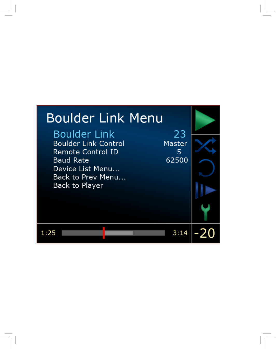
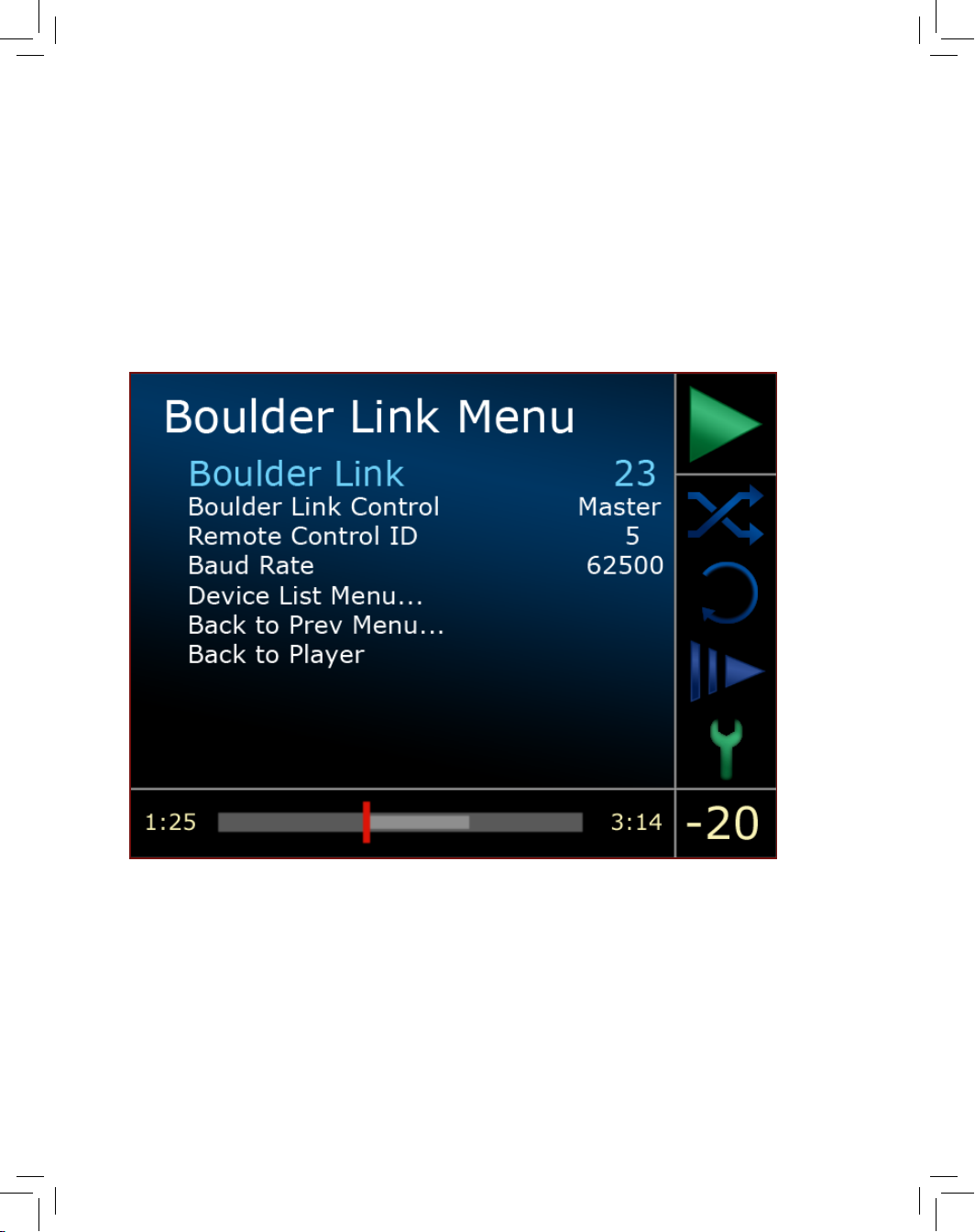
Boulder Link Menu
The Boulder Link Menu is used to view or adjust functions related to
the Boulder Link system. To navigate the Boulder Link Menu, use the
Navigate Up or Navigate Down button and then press Enter once the
desired option is highlighted. The following options are available in
the Boulder Link Menu:
Boulder Link ID
The Boulder Link ID shows numeric ID number that has been
assigned to the 1021 for use in the Boulder Link system. The
factory default ID number for the 1021 is set to 23 at the
factory and/or when a Factory Reset is performed.
Setup and Programming
Setup &
Programing
Page 74
12-21
Page 75

12-22
The Boulder Link ID can be set for values of 16 through 31. To
select an ID number, use the Navigate Left or Navigate Right
button to select the specic ID number you prefer.
For further information regarding Boulder Link, please see
page 13-2.
Boulder Link Control
The Boulder Link Control submenu displays the position of
the Master/Slave switch on the rear panel. No settings can
be changed from this submenu. The switch position must be
changed on the rear panel.
For further information regarding Boulder Link, please see
page 13-2.
Remote Control ID
The Remote Control ID submenu determines the ID setting of
the remote control system.
The Remote Control ID can be set to 0, 1, 2, 3, 4, 5 or 6. The
factory default remote control ID number for the 1021 is set to
5 at the factory and/or when a Factory Reset is performed.
To select an ID number, use the Navigate Left or Navigate
Right button to select a specic Remote Control ID number.
This feature is used in conjunction with a wiring change in
the remote control and should always be set at 5 unless the
1021 remote control system interferes with the operation of
other electronics in your home. Consult your dealer before
changing this setting.
Baud Rate
The Baud Rate setting increases Boulder Link’s compatibility
with other brands of remote control equipment.
Setup and Programming
Setup &
Programing
Page 76
12-23
Page 77

12-24
The Baud Rate submenu can be set to 4800 or 62500. The
default setting is 62500. To select a baud rate, use the
Navigate Left or Navigate Right button to select a specic
rate. Consult your dealer before changing this setting.
Device List Menu
The Device List Menu indicates the Master/Slave status of the
1021 and if any other Boulder products are connected via
the Boulder Link system. Ampliers are indicated as “AMP,”
followed by their Boulder Link ID number (for example, AMP
01). Other components are indicated as “DEV,” followed by
their Boulder Link ID number.
Back to Prev Menu
Pressing the Enter button while Back to Prev Menu is
highlighted will take you back to the Boulder Link Menu.
Back to Player
Pressing the Enter button while Back to Player is highlighted
will exit the menu system and take you back to the Track List
display.
Factory Reset Menu
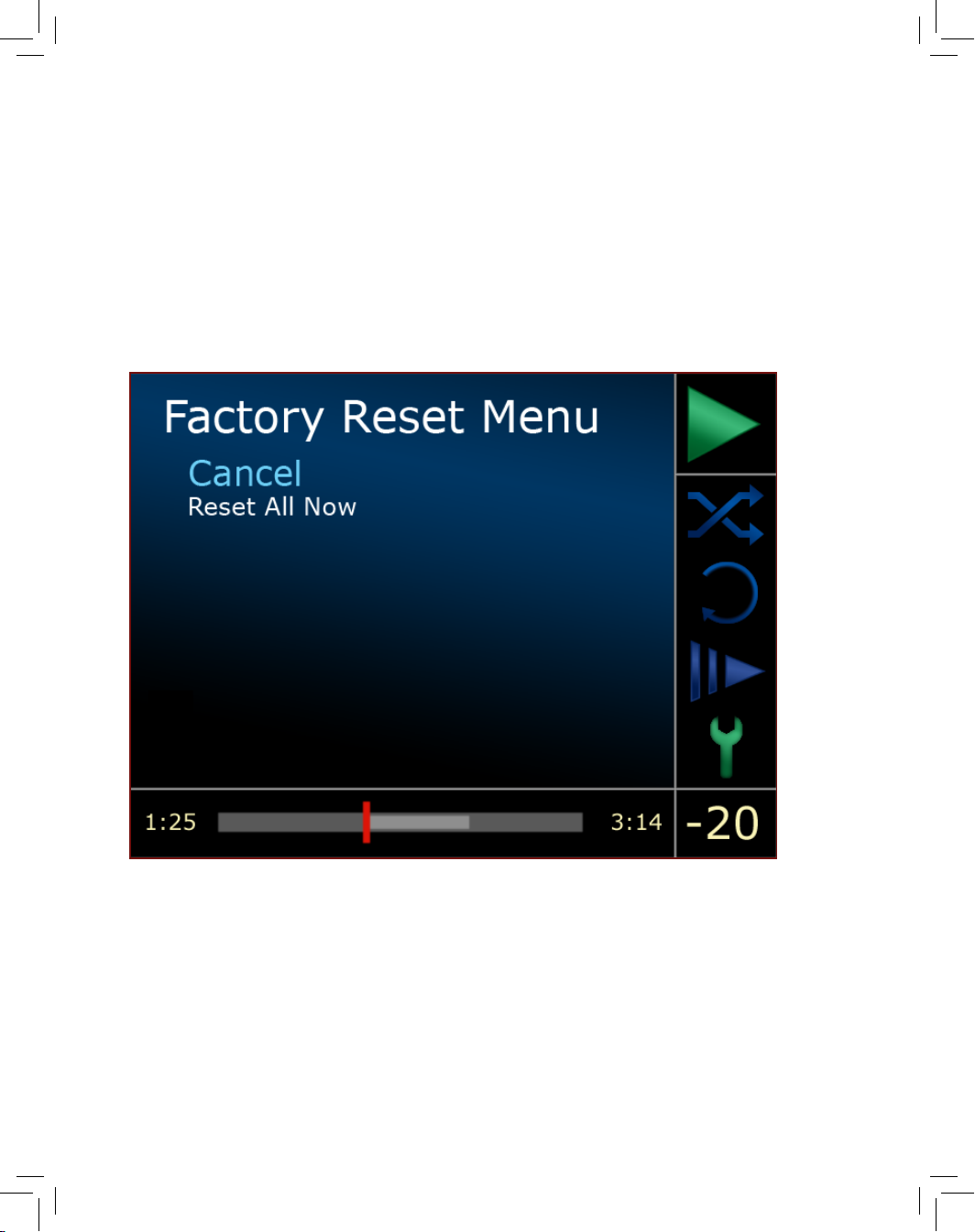
The Factory Reset Menu is used to return all programmed menu and
submenu settings to factory defaults. Menu options of Cancel or Reset
All Now are available.
To navigate the Factory Reset Menu, use the Navigate Up or Navigate
Down button and then press Enter once the desired option is highlighted.
Note: If the Enter button is pressed when the Reset All Now option is
highlighted, all software options will be reset to factory defaults and all
of your programmed preferences will be lost.
Setup and Programming
Setup &
Programing
Page 78
12-25
Page 79

12-26
Back to Player
The Back to Player menu option will exit the menu system and
return the display to the Track List.
To activate the Back to Player command, highlight the Back
to Player menu option and press the Enter button.
Setup and Programming
Setup &
Programing
Page 80

13-1
Page 81

13-2
Boulder Link
Boulder Link is a means of interconnecting most Boulder products so
that their microprocessors can communicate and pass important
information. Among the key features, Boulder Link allows sequential
turn-on of power ampliers and other products when the 1021 is
brought out of Standby mode. When the 1021 is set as the Master,
power ampliers can also send messages to the player, which are
then shown on the display. When the 1021 is installed in a Boulder
Link enabled system with a Boulder preamplier, the volume control
of the preamplier will respond to commands from a remote control,
however the 1021 volume setting will not change.
The following is a description of how volume control works with the
1021 CD Player and preampliers using Boulder Link.
The general rules for Boulder Link and remote control transmissions
are as follows:
Only the component that is set to the 1. MASTER position looks for
IR remote control commands.
If the Master can decipher an IR remote transmission, the 2.
Master will perform the action requested and also send out
any Boulder Link or IR commands accordingly.
If the Master cannot decipher the IR remote transmission, or 3.
the remote address is wrong, then the Master packages the
code and sends it out through the Boulder Link connection to
be used by any Slave that can utilize it.
If a Slave receives an IR remote package via Boulder Link, 4.
it will try to decipher it, and if the address is correct (for the
Slave), it will perform the action requested but will not send
out any results to the Boulder Link buss. This prevents an
“echo” from being generated on Boulder Link.
The 1021 breaks rule #2 in that even though it is able to decipher
remote Volume Up/Down actions, it also sends remote Volume
Up/Down transmissions out via Boulder Link to be utilized by any
preamplier that is connected to the system.
Boulder Link
Page 82

13-3
Page 83

13-4
Using a Preamplier with Boulder Link
To use a preamplier with the 1021 Disc Player, the preamp, the disc
player, and the remote control must all have the same IR remote
address (NOT Boulder Link address). For further information regarding
the IR remote address of each Boulder product, please contact your
dealer.
The 1021 volume control should be set to “Fixed,” except in the
scenario described in the following paragraph.
There are two basic Boulder Link congurations that can be set up
between the 1021 and a preamplier, either with the 1021 set to
be a Slave and the preamplier set to Master, or vice versa. Either
conguration should work equally well, however it is preferable that
the preamplier is set to Master so that amplier power up will be
initiated by the preamplier instead of the disc player.
Connecting Boulder Link
Boulder Link cables in various lengths are available as an accessory
from your dealer. Please contact your Boulder dealer to order the
proper cable lengths and accessories.
Turn off all products that are to be linked via their Master AC Switch
before connecting any Boulder Link cables and setting Boulder Link
ID and Master/Slave switches.
Two connections are provided on the back of all Boulder Link
enabled products. All the chassis are connected together in a
“daisy chain” manner. Start by connecting one chassis to another,
then from that chassis to the next until all are connected. The order
does not matter.
A special interface may be obtained to enable Boulder Link to be
used with other control systems such as Crestron or AMX. Please
contact your Boulder dealer for further details.
Boulder Link
Boulder Link
Page 84

13-5
Page 85

13-6
Connecting Older Generation Products via Boulder Link
If you are using the 1021 Disc Player with certain other Boulder
products, a Boulder Link Adapter Box (BLAB) may be required to
make the connection.
Although the connectors are mechanically different between the
series, they are electrically the same, thus allowing the various series
to be mixed.
Please contact your Boulder dealer for further information.
Setting Boulder Link Switches
The Boulder Link Master/Slave switch is located on the rear panel.
Every Boulder Link system must have only one “MASTER” component,
and only one component can be set to MASTER. Usually this is the
preamplier or CD Player. Power ampliers and other products not
having a MASTER/SLAVE switch can never be “MASTER.” The 1021’s
Boulder Link MASTER/SLAVE switch will normally be set to MASTER,
except in the situation described below involving a preamplier.
Setting Boulder Link ID Numbers
Each component in a linked system is required to have a unique
Boulder Link ID number. The 1021 ID is preset to 23 at the factory
and/or when a Factory Reset sequence is executed.
The 1021’s Boulder Link ID Number is programmed in the Boulder Link
submenu. The 1021’s Boulder Link ID should be set to 23. The disc
player’s rear panel Boulder Link switch should then be set to SLAVE if
the player is to be used with a preamplier.
Each Boulder power amplier has a thumbwheel switch on the
rear panel. Start by setting the rst switch to 0 or 1 and then going
up from there without any duplication. Use of the lowest numbers
will speed up turn on as each amplier is allowed about three (3)
seconds before the next. This spreads out the power line inrush
currents thus preventing house circuit breakers from unnecessary
tripping. In addition to the 1021, up to 15 preampliers and 16 power
ampliers may be connected together in one Boulder Link system.
Boulder Link
Boulder Link
Page 86

13-7
Page 87

13-8
Power Up via Boulder Link
With each component connected together with a Boulder Link
cable and individually connected to the AC mains, pressing the
1021’s front panel Standby button will begin the turn-on sequence of
all components. When a “MASTER” 1021 is powered up, it will search
for any “SLAVE” units connected to it. As the master nds each slave,
the slave’s ID number will be shown on the display.
If any of the connected slaves are ampliers, each time the master
is brought out of Standby mode it will display “WAITING FOR AMPS.”
Each amplier will be turned on in the order of their Boulder Link ID
number. To minimize turn on time, the ampliers’ Boulder Link IDs
should be set to the lowest sequential numbers possible other than
0. For example, use 1, 2, and 3 instead of 13, 14, and 15. An amplier
set to ID 15 will take 47 seconds to turn on.
A 1021 set to “SLAVE” will display “THIS UNIT SLAVE #23”. If there is
no component set to “MASTER,” the 1021 will display “THERE IS NO
MASTER!” In this case, the 1021’s rear panel MASTER/SLAVE switch
should be set to MASTER. It may take up to 30 seconds for the 1021
to recognize the switch change.
Boulder Link Messages
Each component in the system can send a message to the 1021,
which is then shown in the Progress Bar portion of the display. This is
particularly helpful in conrming the operating status of each power
amplier in a multiple amplier system.
“AMPLIFIER 1 ERROR” means that an internal power supply
has failed and Amplier 1 has turned itself off to protect the
speakers from damage.
“AMPLIFIER 1 HAS DC” means that Amplier 1 has turned itself
off due to a DC offset voltage being detected at its inputs.
“AMPLIFIER 1 IS HOT” means that Amplier 1 has turned itself
off due to a higher than normal temperature condition on the
heatsinks.
Boulder Link
Boulder Link
Page 88

13-9
Page 89

13-10
“AMPLIFIER CLIP” means that the amplier’s output has
momentarily reached its output voltage limitation.
“UNIT 1 IS OFFLINE” means that the slave is no longer
responding via Boulder Link. Its Boulder Link cable may have
become disconnected, or it may have been disconnected
from AC mains power.
“UNIT 1 IS ONLINE” means that the slave is now responding via
Boulder Link in a normal manner and has been recognized by
the master.
Boulder Link
Boulder Link
Page 90

14-1
Page 91

14-2
Specifications
FORMATS ...................................................CD, CD-R, DVD-R, DVD+R, FLAC,
WAV (PCM), AIFF, MP3, OGG Vorbis
DIGITAL OUTPUT ................................................1 x AES3, Converts to S/PDIF
ANALOG OUTPUTS ............. 2 Pairs Balanced, Adaptable to Unbalanced
OUTPUT LEVEL .............................4.0V Balanced, 2V Unbalanced @ 0dBFS
VOLUME CONTROL RANGE .........................................80 dB in 1.0 dB Steps
DISPLAY OUTPUT .........................................640x480 VGA 15-Pin Connector
INTERNET ............................................................... RJ45 Ethernet Connector
SYSTEM ............................................................Boulder Link, 12V Trigger, IR In
SIGNAL TO NOISE RATIO ............................. 114 dB, 22-22k Hz, Unweighted
THD+N, 0dBFS ..........................................less than 0.0016%, 20 Hz to 20k Hz
FREQUENCY RESPONSE ........................................................-0.5 dB at 20kHz
DIMENSIONS ....................18 W, 9.25 H, 15.25 D inches, (46 x 23.5 x 39 cm)
WEIGHT ............................46 lbs., Shipping: 60 lbs. (21 kg, Shipping: 28 kg)
POWER CONSUMPTION ...............75W Max, 50-60 Hz, Voltage by Country
Specifications
Page 92

15-1
Page 93
15-2
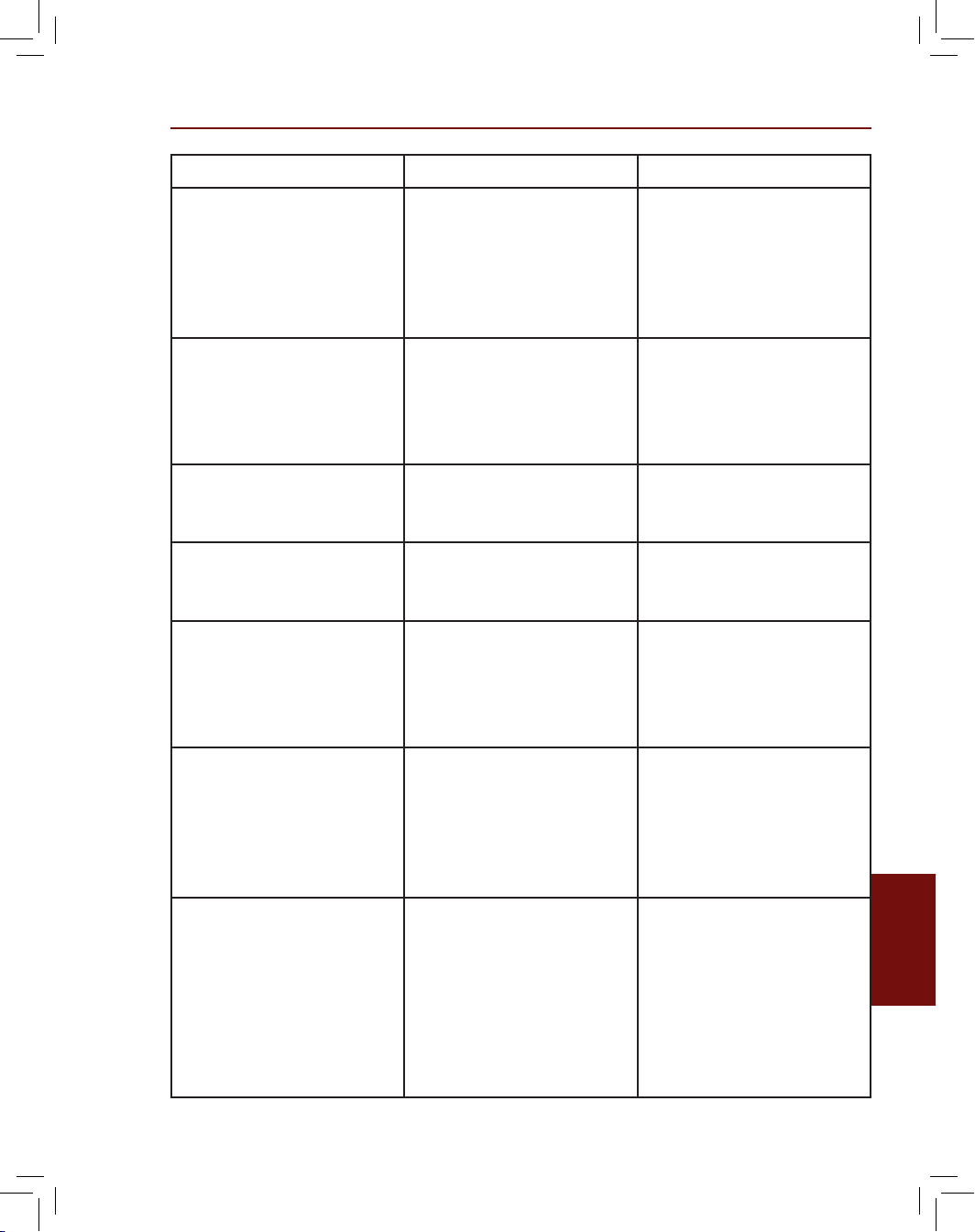
Symptom Cause Remedy
Unit does not power upAC cord not
plugged in or is
not turned on; no
power connection
to AC mains.
Connect power
cord to AC mains
or rear panel, turn
power ON via
Master AC Switch
on rear panel.
Player switches
Standby mode
Player set up to
switch to Standby
if inactive for a
specic length of
time
In Setup menu,
change standby
timer to desired
delay or OFF.
Volume or output is
very low when using
a preamplier
Output set to
Variable in Setup
menu
In Setup menu,
change volume
control to Fixed
Volume control
does not respond
Output set to Fixed
in Setup menu
In Setup menu,
change volume
control to Variable
Display goes blank
or white
Player must be
rebooted.
Brightness is all the
way down.
Unit is in Standby.
Turn unit OFF for 30
seconds via Master
AC Switch on rear
panel and back ON
again
Units ejects discs
without playing
them
Unsupported
le type on disc,
unsupported disc
type or blank disc
inserted; damaged
or defective disc
Remove disc
and replace with
supported format
Some tracks do not
appear on Track List
and are not played
Track or le names
are truncated.
Some will limit
le names to 32
characters and cut
off the le name
Correct le name
for missing tracks
in computer and
reburn disc. File
names must include
the full le type sufx
(.wav, .aiff, .ac.,
.mp3, or .ogg)
Troubleshooting
Troubleshooting
Page 94

15-3
Page 95
15-4
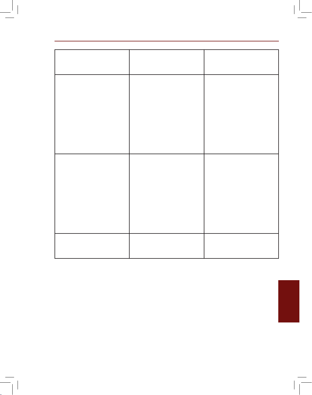
Not all tracks on
disc are played
A play list has been
created and must
be cancelled.
Press the STOP
button twice to
cancel the play list
No remote control
or IR response
Batteries in remote
control are dead,
something is
connected to the
IR minijack on the
rear panel, Master/
Slave switch set to
Slave, Remote ID set
incorrectly
Replace remote
control batteries
with fresh set,
disconnect minijack
connection, set
Master/Slave switch
to Master, or make
sure Remote ID in
setup menu is set
to 5
Disc will not eject Defective or
improperly loaded
disc
Locate the small
hole in the disc
loading drawer
slot and insert
a straightened
paperclip in hole to
open drawer. Be
very careful not to
scratch the chassis
nish.
AES digital output
does not function
Digital output is
turned Off in Setup
menu
Turn AES digital
output ON in Setup
menu
Troubleshooting
Troubleshooting
Page 96

16-1
Page 97

16-2
For warranty information, please contact your Boulder dealer.
Warranty
Warranty
Page 98

 Loading...