

Page 1

ELITE Test Systems
01
/Quick
Start
Wiring
Botron Company Inc.
Page 2

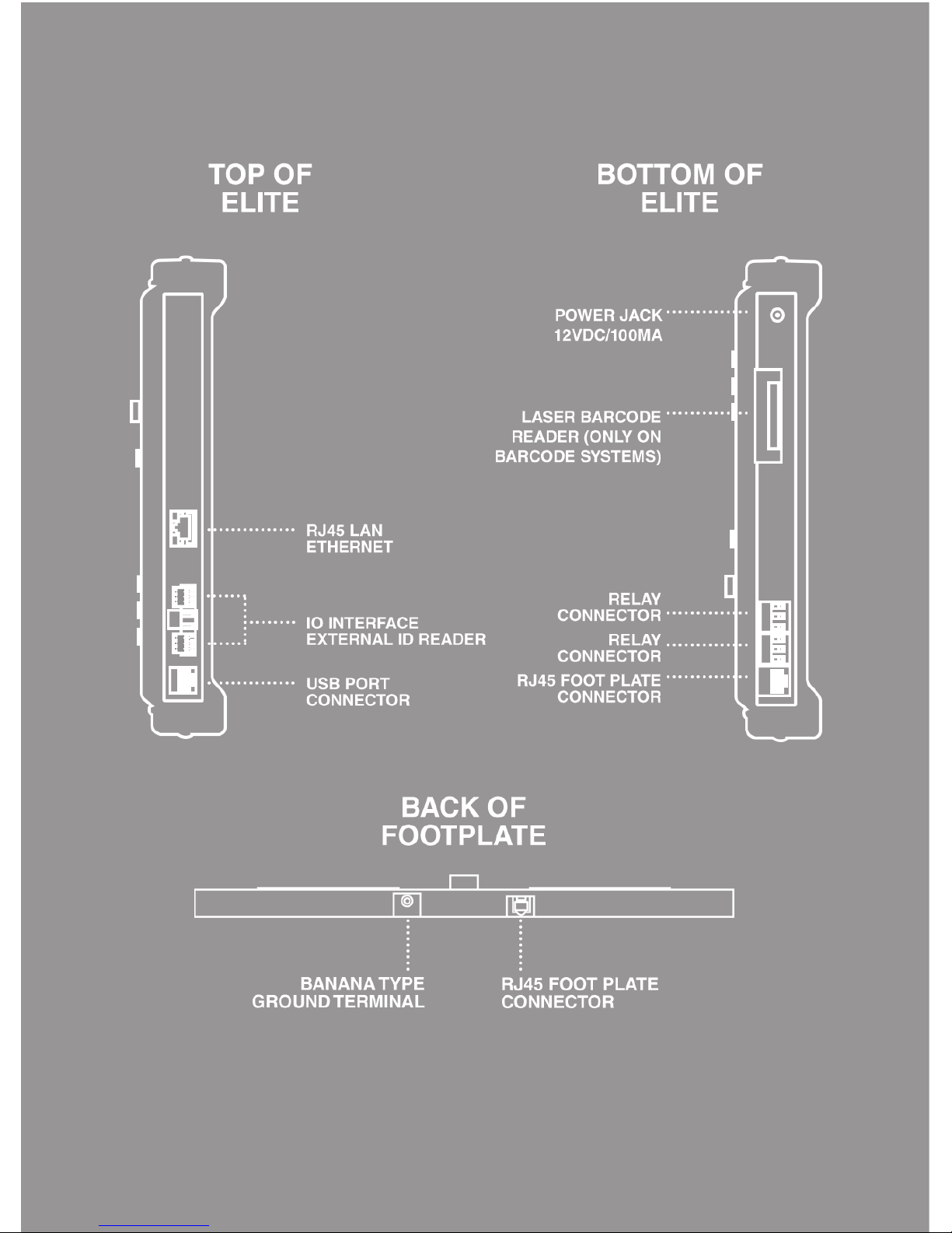
This guide shows you how to assemble and wire your ELITE Test System,
and gets you ready for everyday use. Once you have selected the perfect
place to install your test system please refer to the accompanying Quick Start
Guides; 02 Quick Start Web UI and 03 ELITE Data Systems to finish your
setup.
GETTING
TO KNOW
YOUR
ELITE
P1
Page 3
P2P2
Page 4

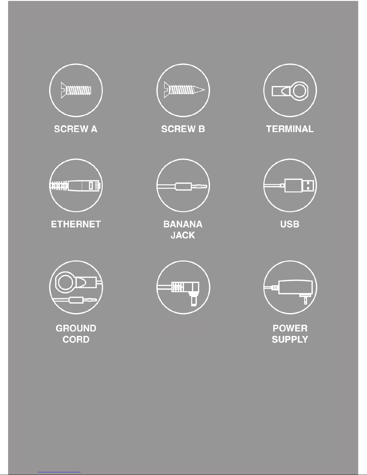
For your reference we have included an illustrated list of all components to
help aid with the installation of your ELITE Test System.
TOOLS
OF
THE
TRADE
P3
Page 5
DC OUTPUT
P4
Page 6

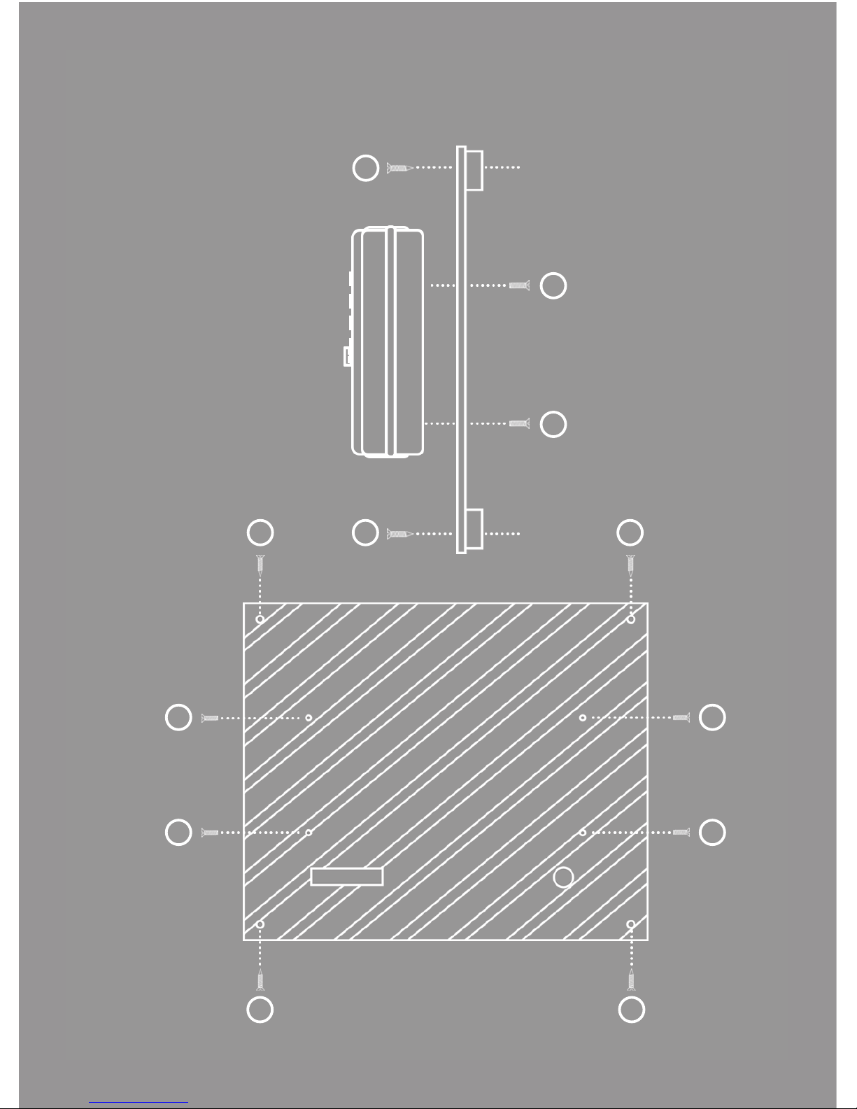
Step 1. Install 4 screws through the back of the Wall Plate and into the
ELITE Tester.
Step 2. Install 4 screws through the Wall Plate onto desired wall
location (recommended 4 feet from floor) with a clear area below for a
footplate.
MOUNT
YOUR
WALL
PLATE
P5
B
A
Page 7
A
A
A
A
A
A
B
BB B
B B
P6
Page 8

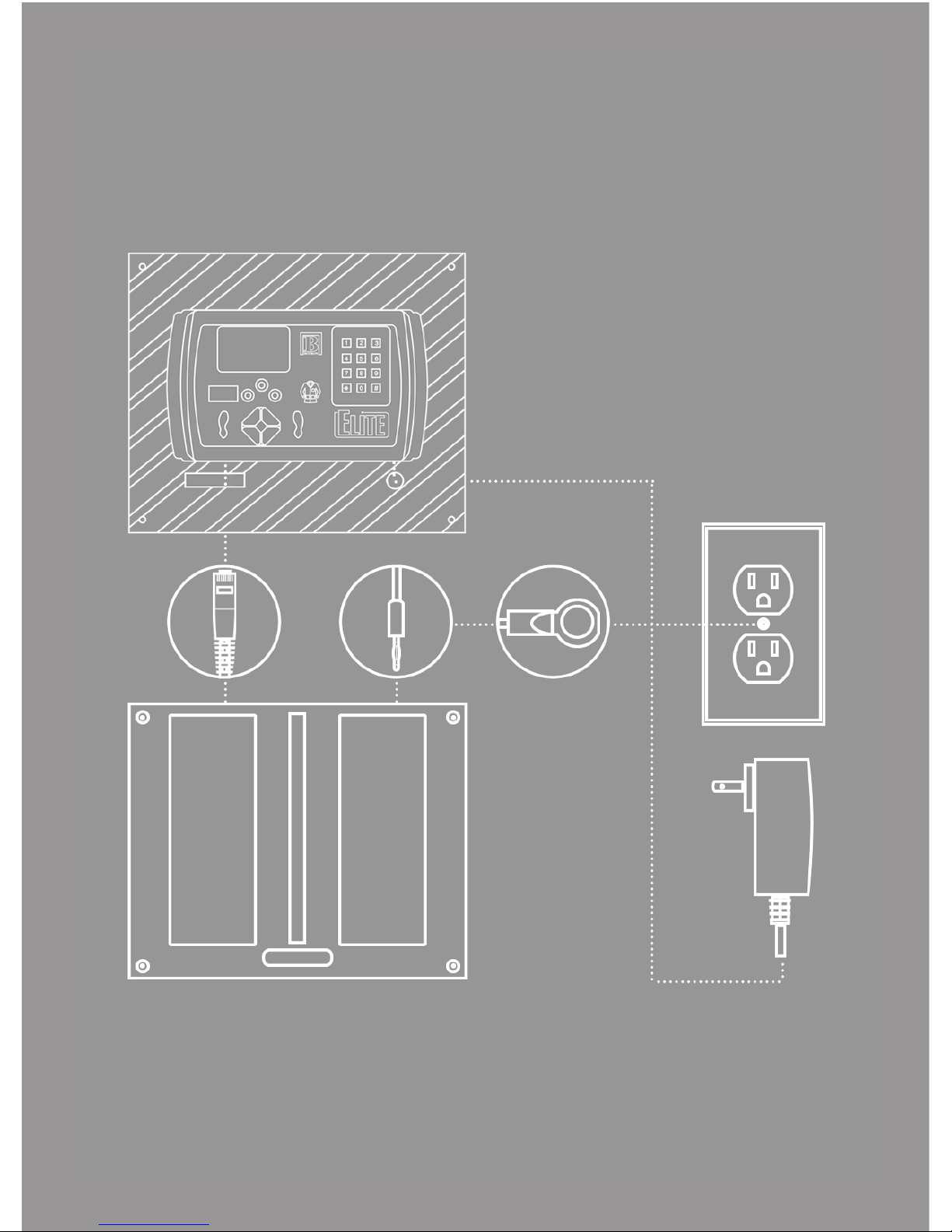
As you will notice, the wall plate comes with pre-cut wire channels for cable
management.
Step 1. Using the wire channels, connect the DC Output and RJ45 cable to
their respective ports on the bottom of the ELITE Tester.
Step 2. Connect the other end of RJ45 cable to the footplate.
Step 3. Grounding Your Footplate
3.1 Using the supplied Ground Cord, insert the banana plug into the
footplate.
3.2 Connect the ring terminal for the footplate ground to a known good
ground connection.
Step 4. Once you have connected your cables and wires, plug in the ELITE
Tester Power Supply (the ELITE will automatically turn on).
WIRING
YOUR
WALL
PLATE
P7
Page 9
P8
Page 10

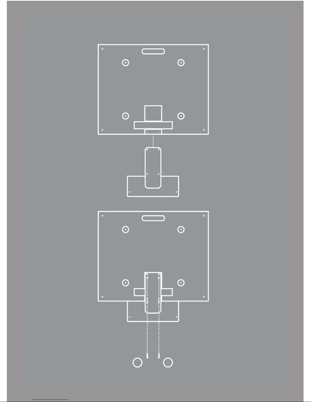
The ELITE footplate comes with 4 pre-drilled holes on the underside to securely
mount the test stand pole to the footplate.
Step 1. Lay the test stand pole on its back with the footplate mounting bracket
pointing upwards.
Step 2. Mount the footplate to the test stand pole using 4 screws into the
underside of the footplate.
MOUNT
YOUR
FOOT
PLATE
P9
A
Page 11
P10
A
A
Page 12

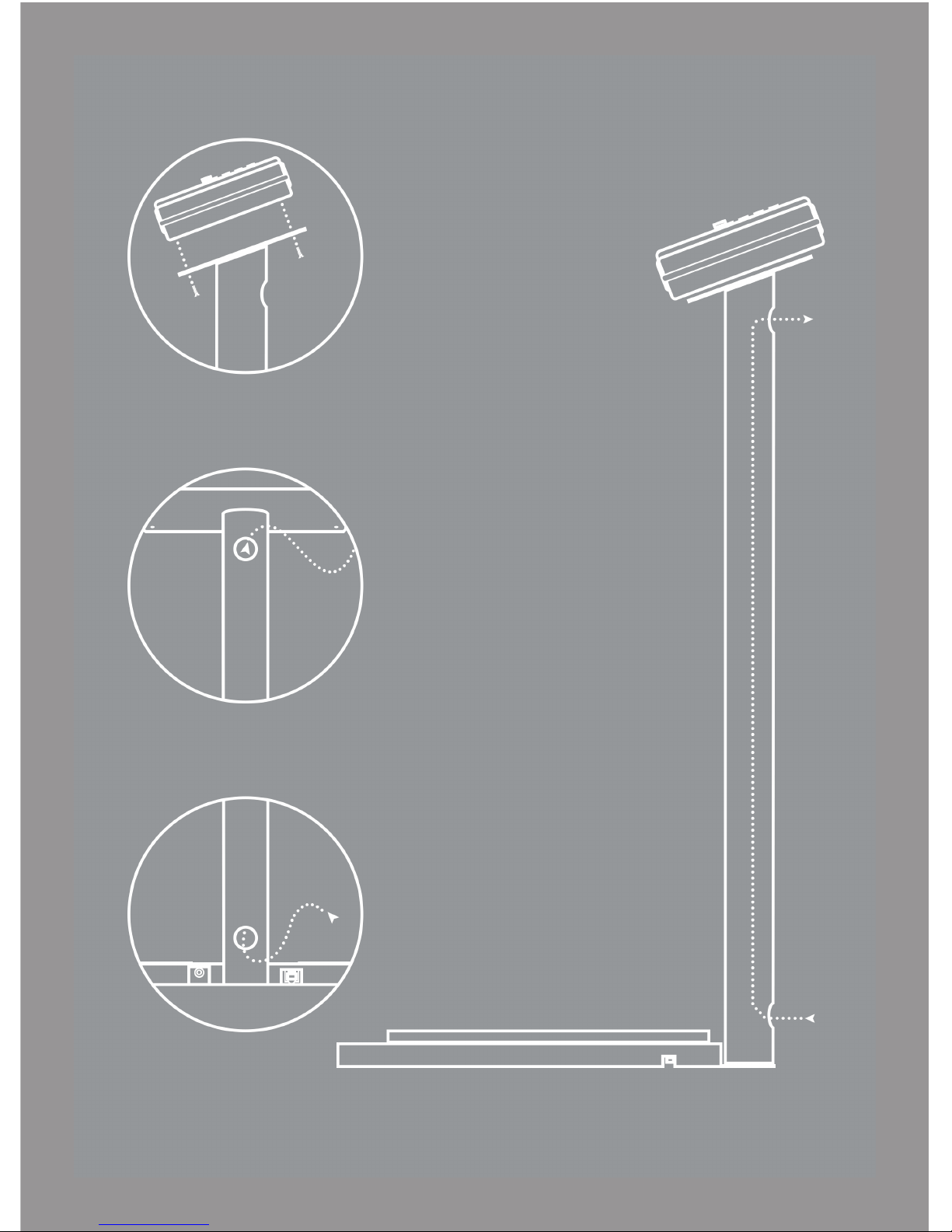
Once you have completed the previous section (Mount Your Footplate):
Step 1. Feed the RJ45 Cable and DC Output from the Power Supply
through the bottom rear opening of the Test Stand Pole. Pull the cables
through the pole and out the top rear opening.
Step 2. Connect the RJ45 Cable and Ground Cord to the footplate.
Step 3. Connect the ring terminal of the Ground Cord to a known good
ground.
Step 4. Connect the DC Output and RJ45 Cable into the bottom of the
ELITE tester.
Step 5. Connect the Power Supply into a 120V AC outlet.
WIRING
YOUR
FOOT
PLATE
P11
Page 13
P12
Page 14

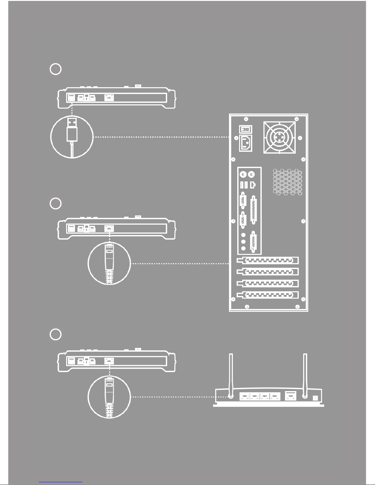
Follow the diagram for the best suited network connection type.
Direct USB Connection - Firmware Updating
Connect from the ELITE using the USB cable to an available USB port on a
PC.
Direct Ethernet Connection - Data Communications
Connect from the ELITE using the Ethernet cable to an available Ethernet
port on a PC.
Ethernet Network Connection - Data Communications
Connect from the ELITE using the Ethernet cable to an available Ethernet
port on a router.
CONNECT
TO
YOUR
NETWORK
P13
A
B
C
Page 15
P14
A
B
C
Page 16

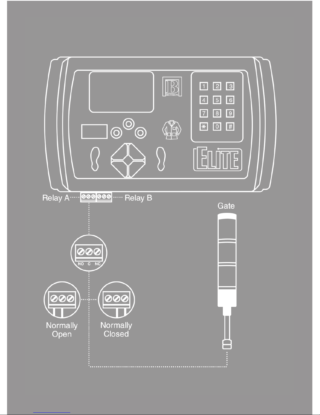
There are two relays, A & B, on the bottom of the ELITE Tester. Each relay
has 3 inputs; Normally Open (NO), Common (C), and Normally Closed
(NC). How you wire to your ELITE depends on the type of switch on your
external device. Once you have determined the type of switch, follow the
illustration for connection procedure.
A is triggered on an entry event (passing test result), acting as a switch to
control outside gates, such as doors, light towers, and turnstiles upon a
passing test result.
B is commonly used for exiting, when access is controlled by the ELITE
Test System. It works in conjunction with external I/O devices connected to
the tester such as ID readers and IR exit switches.
B can also be set to mirror Relay A and switch a second device upon an
entry event.
CONNECT
TO
YOUR
RELAYS
P15
Page 17
P16
Page 18

AN IMPORTANT NOTE
Please read this document and check that your system is set up carefully
before you first use your ELITE Test System.
LEARN MORE
You can find more information and learn even more about ELITE features at
www.botron.com/elite.
SUPPORT
Your ELITE comes with 90 days of technical support and one year of
hardware repair warranty coverage. For more information please contact:
Phone: 1-623-582-6700
email: [email protected]
MAILING
Botron Company Inc.
21601 N. 21st Avenue
Phoenix, AZ 85027
All rights reserved. Designed by Botron.
Page 19

ELITE Test Systems
02
/Quick
Start
Web UI
Botron Company Inc.
Page 20

Welcome to the ELITE V2 Web UI. Here you can control the settings of your
device such as VTR (Variable Test Resistance) Technology, calibration, relays
and much more. The ELITE V2 Web UI is an interactive web app that works
in most browsers across many platforms, such as mobile phones, tablets and
desktops. This gives you access to your test equipment anywhere you go
within your network.
Once you have connected your device to your network, access the Web UI
by entering the IP address in the browser of your choice. The IP address is
automatically obtained by the ELITE V2 once connected to your network.
This Quick Start Guide is to give you an overview of the screens and features
of the Web UI.
YOUR
ELITE
V2
WEB UI
P1
Page 21
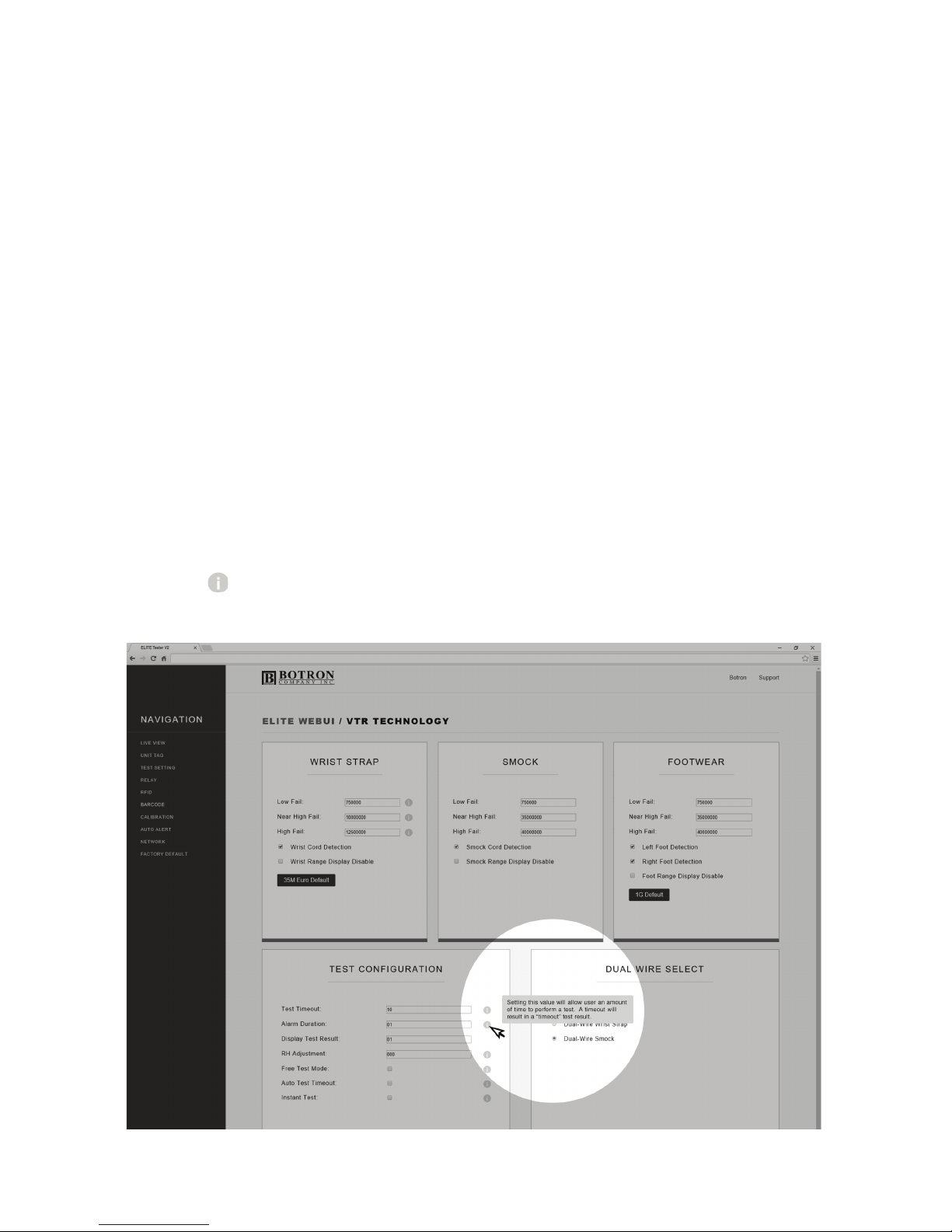
GETTING STARTED
Please check that your Ethernet cable is securely connected to the ELITE.
If you need assistance on connecting your device to your network please
refer to Quick Start Guide 01 - Wiring & Mounting.
To find your IP address, hold down the # key on the keypad, please wait for
it to beep again and release. This will bring you into the TCP/IP information
screen, here you can see the device network information, including the IP
address.
Record the IP address and enter it into your internet browser URL bar.
The ELITE Web UI works with internet browsers across mobile devices and
desktops.
Look for Tooltips on the Web UI screens for a more detailed explanation
on each feature.
P2
Page 22
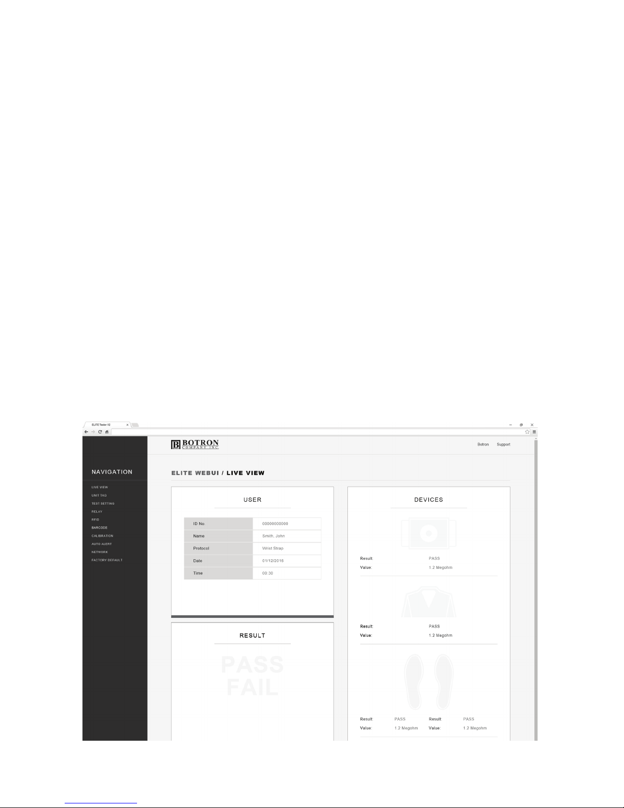
LIVE VIEW
The Live View screen displays realtime information about the personnel
interacting with the equipment.
There are 3 tiles: User, Result and Devices.
The User information tile will update the ID number, Name, Protocol (Test
Requirement) as each user inputs their ID.
The Result tile will light up PASS in Green, or FAIL in Red depending on
the test outcome.
The Device tile is also interactive. Grayed out icons will change to either
Green, Red, or Yellow depending on the test result. It also displays the
resistance value for each device.
P3
Page 23
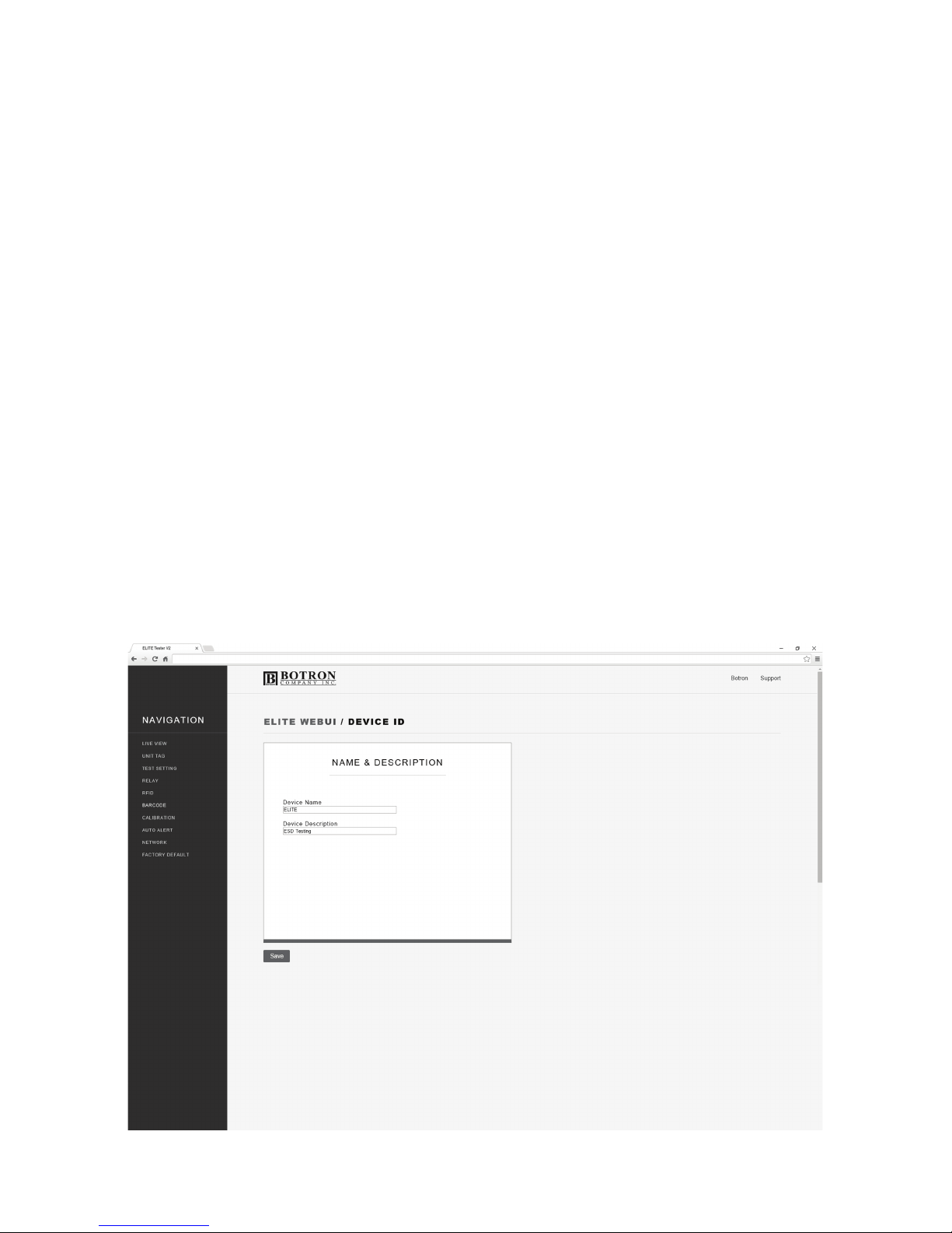
UNIT TAG
The Unit Tag page is where you can name your device. If you have multiple
ELITE Testers or your lab areas are tagged internally, use the provided
fields to help identify your testers location.
The description field can be filled out to further help identify the device,
especially if grouped with other testers’ in the same location.
P4
Page 24
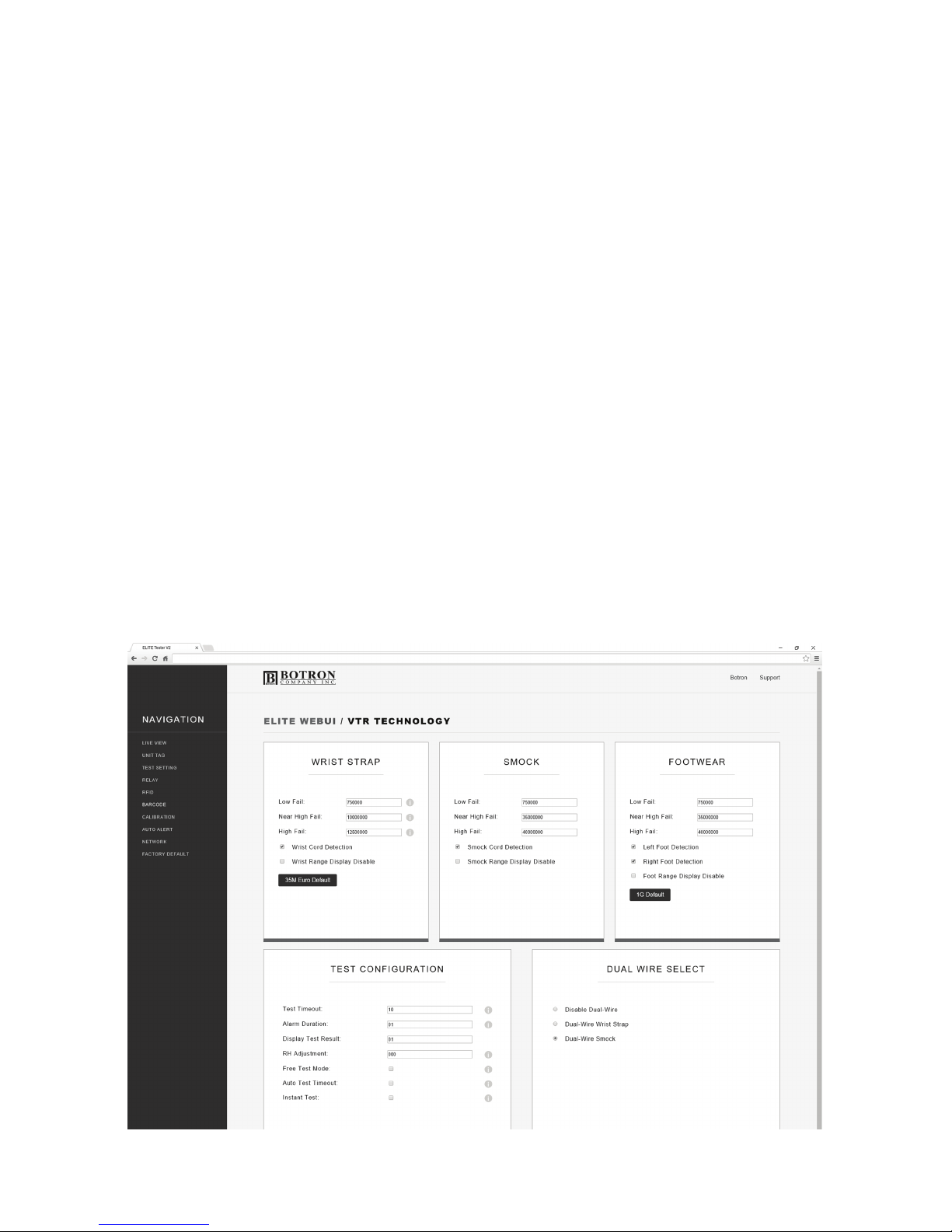
TEST SETTINGS
VTR (Variable Test Resistance) Technology gives you all the control and
customization over your test settings. In this screen you can set the Low
and High Fail as well as our unique and powerful Near Failure adjustment
for Wrist Strap, Smock/Garment, and Footwear. You will also notice that you
can toggle display and auto detection on/off for each device.
Device Titles:
Adjust the High, Low, and Near Fail settings of each device (in Ohms).
Test Configuration:
Control various timing controls and configure how a test is performed.
Dual Wire Select:
The Dual Wire jack on the ELITE works with either a Wrist Strap or
Smock/Garment. You can select either of these options or disable the jack
input.
P5
Page 25
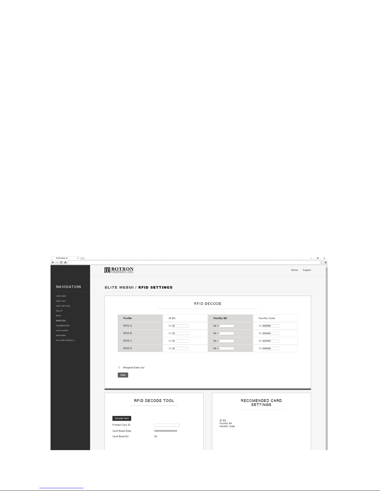
RFID
Completely unique to only ELITE Complete Test Systems, you can decode
up to 4 RFID bit rate types directly on your ELITE Test System.
RFID Decode Tool:
To enter RFID Decode Mode select Decode Card.
Recommended Card Settings:
This will populate with the card data you will need to input in the RFID
Decode tile.
RFID Decode:
This tile is where you enter the information from the Recommended Card
Settings tile.
P6
Page 26
P7
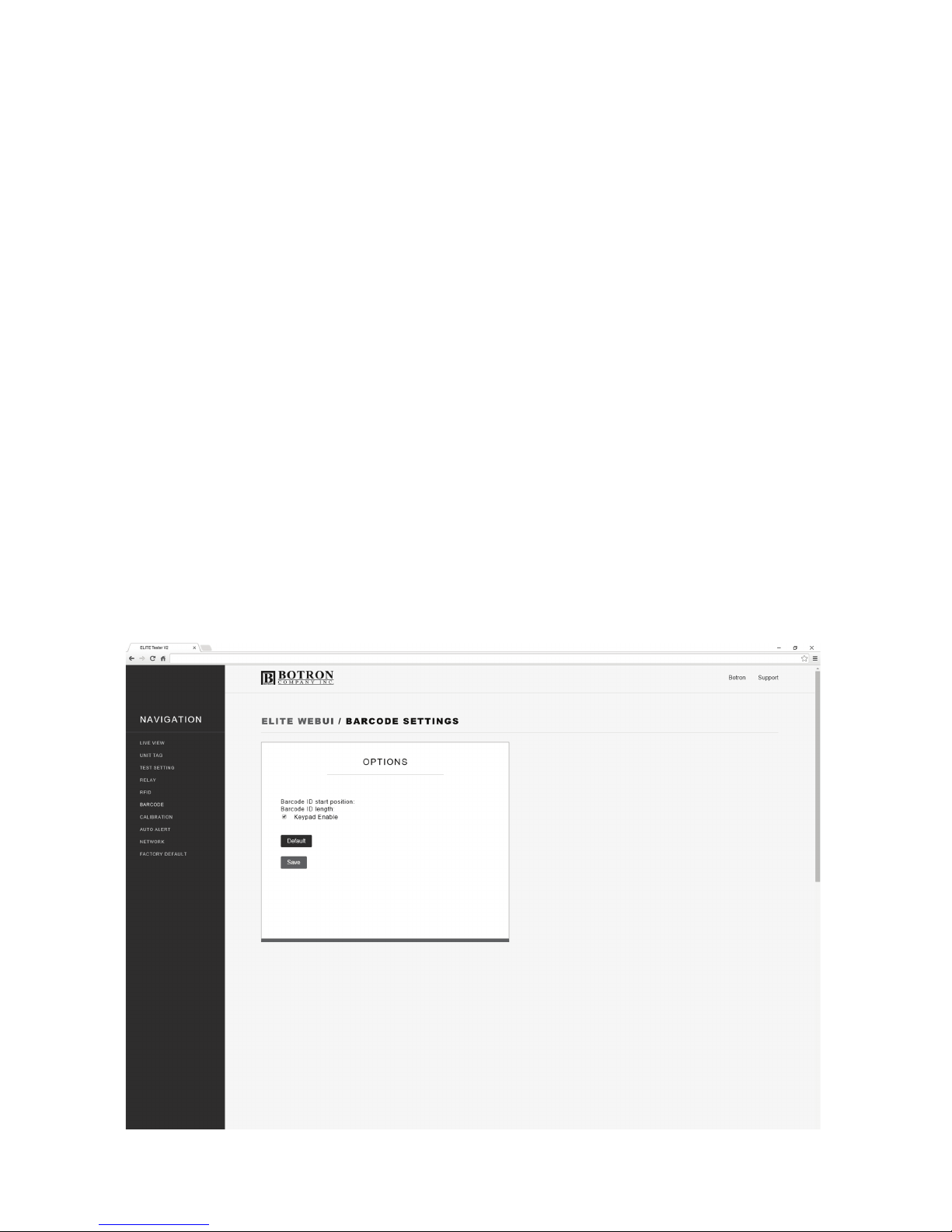
BARCODE SETTINGS
For those with barcode type IDs, in this tab you can control what
information the scanner needs to read. In some cases, a barcode may start
and/or end with characters not prudent to the ID number itself.
Barcode ID start position:
This is where the scanner begins reading the characters of the Barcode.
Barcode ID length:
This is how many characters of the string from the start position the
scanner will read.
Keypad Enable:
Enable/Disables keypad ID input.
Page 27
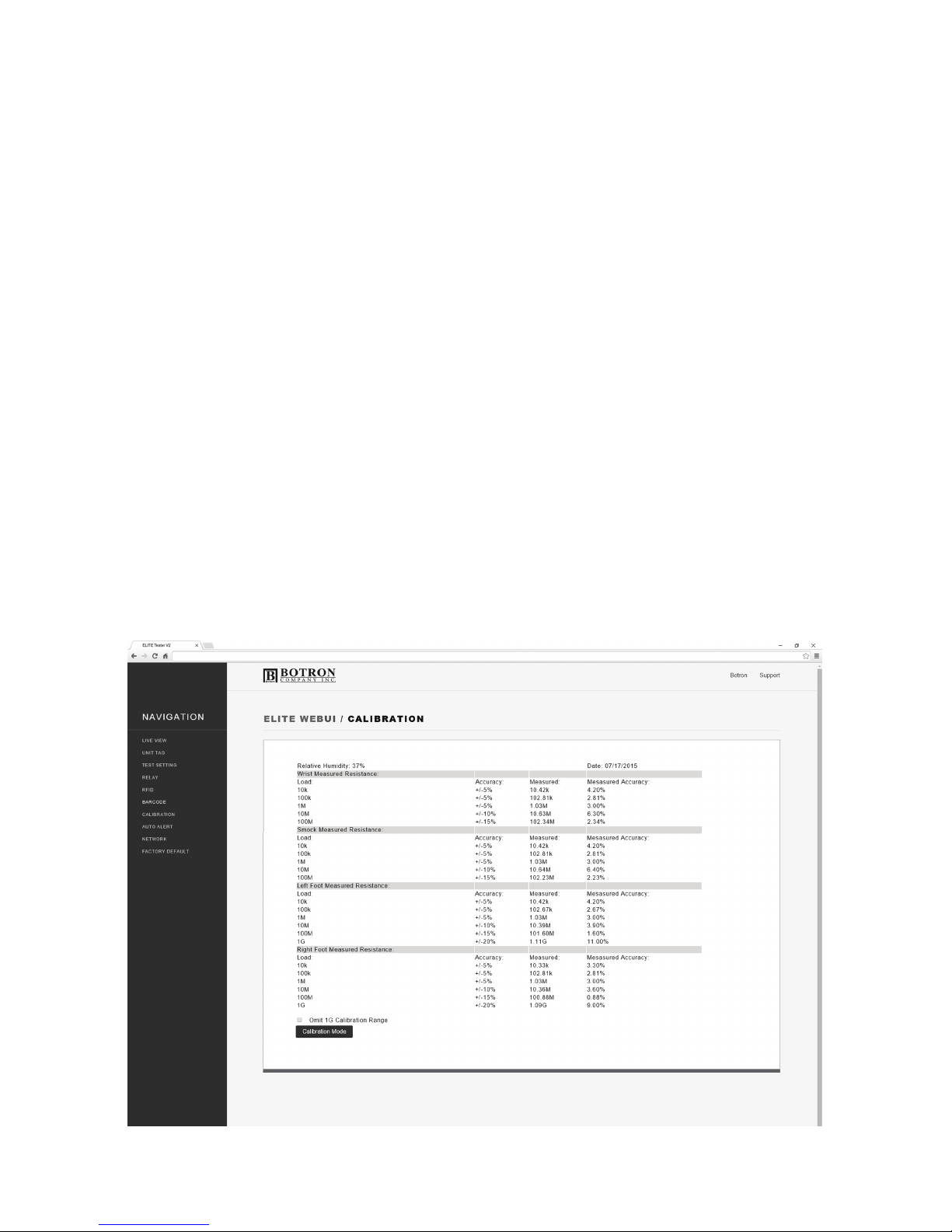
CALIBRATION
All calibration information is time stamped and stored digitally on your test
system. Your calibration certificate is easily accessible though this screen in
the web app when you need it.
All Elite Test Systems come calibrated from the factory.
P8
Page 28
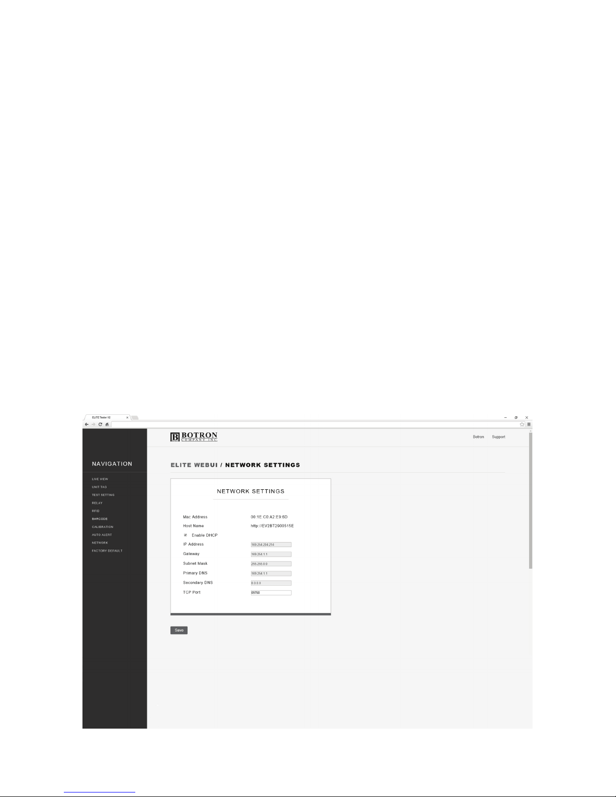
NETWORK
When connected to a PC by the Ethernet cable, the ELITE Tester will
configure it’s Local Area Network (LAN) settings. Assuming you are on the
network, this screen will have stored all the network information regarding
this device.
When Dynamic Host Configuration Protocol is enabled the ELITE Tester's
network settings will be assigned by the network router. By disabling DHCP,
you may manually configure the ELITE Tester's network settings.
P9
Page 29
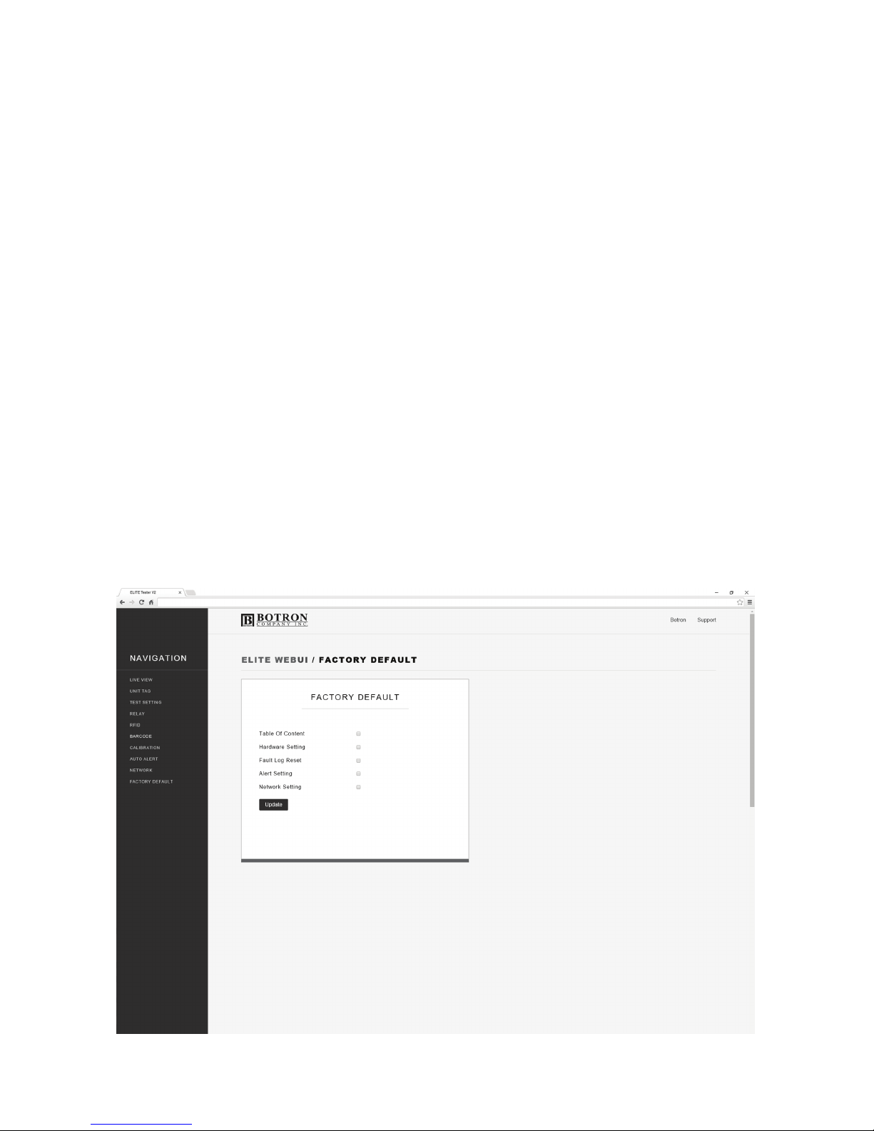
FACTORY DEFAULT
In this screen you can choose to reset individual settings back to a factory
default.
P10
Page 30

AN IMPORTANT NOTE
Please read this document and check that your system is set up carefully
before you first use your ELITE Test System.
LEARN MORE
You can find more information and learn even more about ELITE features at
www.botron.com/elite.
SUPPORT
Your ELITE comes with 90 days of technical support and one year of
hardware repair warranty coverage. For more information please contact:
Phone: 1-623-582-6700
email: [email protected]
MAILING
Botron Company Inc.
21601 N. 21st Avenue
Phoenix, AZ 85027
All rights reserved. Designed by Botron.
 Loading...