

Page 1
Thermostat Digital TH26
Voltage 230V
Consumption:<1W
Temperature control range:5-90
℃
Temperature limitation range:16-60
℃
Temperature switch deviation:Default 1℃
℃
adjustable
)
Ambient temperature:0-50
℃
Protection class:IP20
Load capacity:16A
Connecting Cable:RVV0.5
Housing material:Anti-flame PC
:
Parameter
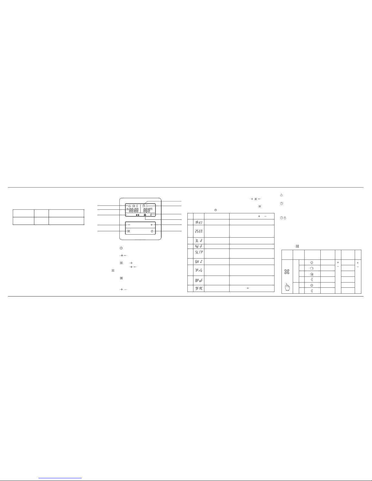
1 Switch on and off
Press button .
2 Temperature setting
Press to set temperature.
3 Clock setting
Press and together for 5s to enter clock setting
mode. Press to switch parameter and press
to revise.
4 Manual / Time period mode selection
Press to switch between Manual mode and Time
period mode
5 lock
Press together for 5s to lock or unlock the
buttons.
.
.
button
.
button
button
button
.
button
.
.Button
button
The display interface and user settings
Temperature
calibration
Temperature adjustment
Adjust by orbutton
Function
Symbol
No.
1
6
4
5
7
8
9
Default OFF
The setting range is
after activation
5~10℃
2
3
5(rest on Sat and Sun. Default)
6 rest on Sun
no rest day
OFF
( )
( )
(shut off Weekly program)
7
thermostat is in off mode
ON:
OFF: thermostat stays in the same
mode before power off (Default)
Press button until --- is displayed
Advanced Settings
These settings are for professional technical personnel.Usually
finished at the initial installation.Press
together
when the thermostat is switched off,and then switch on the
thermostat to enter Advanced Settings. Press to switch
menu. Press to exit current operating mode.
button
button
button
LCD Digital Thermostat can work in Manual mode
or Energy-saving mode. It can be used in electric
heating control system.
It means the internal sensor malfunction when ER0 appears.
Sensor malfunction
Manual Mode
Thermostat works according to the manual set temperature.
Not controlled by progra m.
Period Mode
Weekly recycle. You can set 4 time periods and correspo nding
temperature every day for auto operation.
Time period, temperature, rest d ays can be programmed upon
the customers' request.
Temporary Mode
Thermostat is temporarily switched to manual mode from
current time period mode.
Thermostat will automatically restore to time period mode
when the next time period comes.
Operating mode description
Hold key
for at least 5s to enter period programming
Revise
Revise
Option
Symbol
Default
Time
Default
Temp.
Time
Period
Working
days
Rest
days
Revise time
1
2
3
4
1
2
20
℃
15
℃
22
℃
15
℃
15
℃
06:00
08:00
17:00
22:00
08:00
23:00
Period programming
22
℃
Model
TH26
DescriptionCurrent
16A
Control and limit
by double sensors
Increase button
Decrease button
Menu button
ON/OFF button
Time period mode
Manual mode
Button lock
Anti-freeze function
Heating
Mon~Sun
Time period
Revise
temperature
Restore to
factory settings
Thermostat status
when power on
Set the upper
temperature limit
Switch deviation
0.5~10 ℃.Default 1.0 ℃
Set range .
16~90 ℃
Default 35.0
℃
Anti-freeze function
Rest day selection
and shut off Weekly
program
Installation Instructions
1-8 2-8 3-8 4-8
1 2 3 4 5
6 7
menred
Sensor mode
IN: built-in sensor
OUT: floor sensor
ALL: controlled by built-in sensor
and limited by floor sensor (Default)
Floor limit
temperature setting
16~60℃.Default 45
℃
Page 2
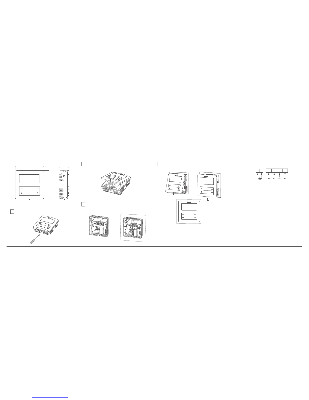
Wiring diagram
Attention
:
This thermostat can be used in full load operation at a p lace
where altitude is no higher than 2,500m. When thermosta t is
installed in a place where the altitude is between 2,500 and
4,200m, the external rated load should be no bigger than 80%
of the nominal power of the thermostat.
>
Power must be off during installation.
Please connect the wires correctly according to diagram.
It s better that the installation height is 1.4m or on the same level of
other wall switches.
Do not install thermostat at non-ventilated location, for example
corner or behind the door.
Do not install thermostat at a place with strong airflow or near cold
and heat source.
Sundries like water, cement slurry, metal particles are forbidden going
inside thermostat. It will damage the thermostat.
>
>
’
>
>
>
Installation Notes
External dimensions
Unit:mm
29
82
82
Thermostat Digital TH26
Installation Diagram
2
3
4
1
Remove the screw at the bottom of thermostat
by screwdriver.
Open the front panel as shown in the following
picture.
Connect the wires correctly according to the
wiring diagram and fix power base on the wall
by screws.
Close the front panel and tighten the screw as
shown in the following pictures to finish
installation.
Installation Instructions
5-8 6-8 7-8 8-8
TH26
1
2 3
4
OUT_NTC
16A
Main
circuit
N
N L
L1
Sensor
 Loading...