

Page 1
English
R
FADE T IME
SPEED
SCENE
RECORD
AUDIO/DEL
CHASE TAP S YNC BLACK O UT
9 10 11 12 13 14 15 16
17 18 19 20 21 22 23 24
25 26 27 28 29 30 31 32
33
34
35
36
37
38
39 40
1 2 3 4 5 6 7 8
M EMORY
0
2
4
6
8
10 0
2
4
6
8
10
CHASE / S CENE
MASTER
SLAVE 1 SLAVE 2 DMX IN
1 2 3 4 5 6 7 8
UP
DOWN
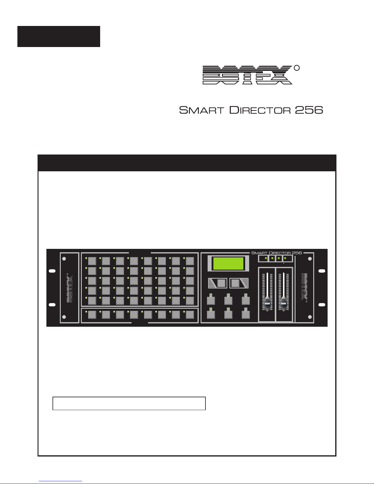
USER'S MANUAL
Please read this manual carefully before use!
Page 2

manual, may be made at any time
Page 3
Contents
Features 1
Technical Specifications 24
General Instructions 2
1. Overview 3
2. Operation Guide 7
1.1 Front View 3
2.1 Recording Scenes 7
2.2 Playback a Scene 9
2.1.1 Record Scenes into a Bank 7
2.1.2 Delete a Scene 8
2.1.3 Preview a Scene 8
2.3.1 Record scenes into a Chase 10
2.3.2 Delete a Step from a Chase 12
2.4.1 Record steps into a Memory 13
2.4.2 Delete a Memory 16
2.4.3 Delete a step from a Memory 16
2.4 Recording Memories 13
2.5 Playback one or more
Chases or Memories 19
2.6 Audio Chase/Memory 20
2.3.3 Delete a Chase 13
1.2 Rear View 6
Improvement and changes to
specifications, design and this
manual, may be made at any time
without prior notice.
All Rights Reserved.
2.3 Recording Chases 10
2.4.3 Modify steps of a Memory 17
2.7 Send Record Data 20
2.8 Receive Record Data 21
2.9 Master/ Slave 1/ Slave 2 Mode 22
R
2.10 Blackout access setting 23
Page 4
DO NOT dismantle or modify the unit.
Protect the unit from excessive dryness or humidity (ideal conditions are between
35% and 80%).
In places with a temperature of over 45 C or less than 2 C/35.6 F./113 F
In places subject to vibrations or bumps.
In places subject to excessive humidity.
NEVER use the unit under the following conditions:
This unit must only be operated by adults. DO NOT allow children to tamper or play
with it.
Packaging material (plastic bags, polystyrene foam, nails, etc.) MUST NOT be left
within children's reach, as it can be dangerous.
After having removed the packaging check that the unit is NOT damaged in any way.
If in doubt, DON'T use it and contact an authorized dealer.
This unit is NOT intended for home use.
NEVER try to repair the unit yourself. Repairs by unqualified people could cause
damage or faulty operation. Contact your nearest dealer.
DO NOT open the unit--there are no user serviceable parts inside.
STOP using the unit immediately In the event of serious operation problems and
either contact your local dealer for a check or contact us directly.
Should any liquid be spilled on the unit, DISCONNECT the power supply to the unit
immediately.
DO NOT make any inflammable liquids, water or metal objects enter the unit.
Read the instruction in this manual carefully and thoroughly, as they give important
information regarding safety during use and maintenance. Keep this manual with
the unit, in order to consult it in the future. If the unit is sold or given to another
operator, make certain that it always has its manual, to enable the new owner to
read about its operation and re lative instructions.
Features
General Instructions
Thank you for your purchase. This product
features include:
1 2
256 basic DMX channels(1-256),
plus 40 on/off switch channels(257-296)
24 banks of 40 programmable scenes
Each scene consists of 256 DMX channels, fade time enable
40 chases, each holds up to 99 steps(recorded scenes).
Playback of one or more chases or memories at a time
8 memories, each holds up to 99 steps(recorded scenes)
All data can be sent or received between two units
Delete unwanted scenes, steps, chases or memories
Blackout master
Built-in microphone for audio chase or memory
Two or more units can be linked
Power failure memory
Page 5
DO NOT dismantle or modify the unit.
Protect the unit from excessive dryness or humidity (ideal conditions are between
35% and 80%).
In places with a temperature of over 45 C or less than 2 C/35.6 F./113 F
In places subject to vibrations or bumps.
In places subject to excessive humidity.
NEVER use the unit under the following conditions:
This unit must only be operated by adults. DO NOT allow children to tamper or play
with it.
Packaging material (plastic bags, polystyrene foam, nails, etc.) MUST NOT be left
within children's reach, as it can be dangerous.
After having removed the packaging check that the unit is NOT damaged in any way.
If in doubt, DON'T use it and contact an authorized dealer.
This unit is NOT intended for home use.
NEVER try to repair the unit yourself. Repairs by unqualified people could cause
damage or faulty operation. Contact your nearest dealer.
DO NOT open the unit--there are no user serviceable parts inside.
STOP using the unit immediately In the event of serious operation problems and
either contact your local dealer for a check or contact us directly.
Should any liquid be spilled on the unit, DISCONNECT the power supply to the unit
immediately.
DO NOT make any inflammable liquids, water or metal objects enter the unit.
Read the instruction in this manual carefully and thoroughly, as they give important
information regarding safety during use and maintenance. Keep this manual with
the unit, in order to consult it in the future. If the unit is sold or given to another
operator, make certain that it always has its manual, to enable the new owner to
read about its operation and re lative instructions.
General Instructions
Warnings
Cautions
Page 6
FADE T IME
SPEED
SCENE
RECORD
AUDIO/DEL
CHASE TAP S YNC BLACK O UT
9 10 11 12 13 14 15 16
17 18 19 20 21 22 23 24
25 26 27 28 29 30 31 32
33
34
35
36
37
38
39 40
1 2 3 4 5 6 7 8
M EMORY
0
2
4
6
8
10 0
2
4
6
8
10
CHASE / S CENE
MASTER
SLAVE 1 SLAVE 2 DMX IN
1 2 3 4 5 6 7 8
UP
DOWN
1. Overview
1. Overview
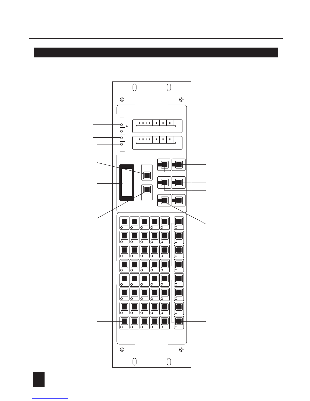
1. Chase/Scene Buttons(1-40)
1.1 Front View 1.1 Front View
3 4
1. Memory Buttons(1-8)
3. Scene Button
4. Chase Button
5. Record Button
6. Tap Sync Button
7. Audio/Del Button
8. Blackout Button
9. Fade Time Slider
10. Speed Slider
11. Segment Display
1
2 3 4 5 6 7 8 9 10
1112 13 14
15
16
17
Page 7

1. Overview
1. Chase/Scene Buttons(1-40)
These 40 buttons are used to record any of the 40 scenes or chases. Also, these
buttons can be used for activating any of the recorded scenes or chases.
1. Memory Buttons(1-8)
These 8 buttons are used to record any of the 8 memories consisting of up to 99
scenes with pre-programmed fade time and chase rate. Also, these buttons can be
used for activating any of the recorded memories.
3. Scene Button
This button is used for activating Scene mode.
4. Chase Button
This button is used for activating Chase mode.
5. Record Button
This button is used for activating Record mode. When its LED flashes, this button can
be used to record scenes or chases.
6. Tap Sync Button
Repeatedly tapping this button establishes the chase rate.
7. Audio/Del Button
This button is used for activating Audio mode. Also, this button can be used to delete
scenes, steps or chases in Recording mode.
8. Blackout Button
This button is used to kill all output when its LED flashes. In record mode, tap this
button to go back step by step.
9. Fade Time Slider
This slider adjusts fade time from instant to 10 minutes.
10. Speed Slider
This slider adjusts chase rate from 0.10 second to 10 minutes.
11. Segment Display
This Segment Display shows the current activity or function state.
Page 8

1. Overview1. Overview
5 6
12. Up Button
This button is used to raise the bank or step..
13. Down button
This button is used to lower the bank or step.
14. Master LED
This LED is lit when this unit serves as a master unit in the linkup.
This LED flashes when another unit serves as a master unit, causing
this unit to stand alone and separate from the linkup.
15. Slave 1 LED
This LED is lit when this unit serves as a slave unit and there is not a
master unit in the linkup.
This LED flashes when this unit serves as a slave unit and is subject to
the master unit. Also, this unit sends DMX address 001-256.
16. Slave 2 LED
This LED is lit when this unit serves as a slave unit and there is not a
master unit in the linkup.
This LED flashes when this unit serves as a slave unit and is subject to
the master unit. Also, this unit sends DMX address 257-512.
17. DMX LED
This LED flashes when DMX signal is present.
Page 9
1. Overview1. Overview
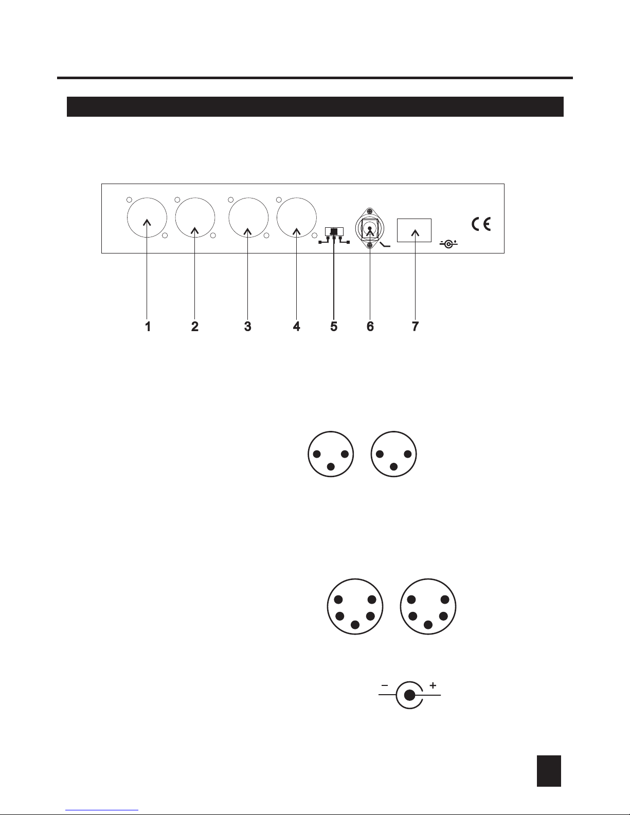
1. DMX Out
This connector sends DMX value to the DMX pack.
1.2 Rear View1.1 Front View
2. DMX In
This connector accepts DMX input signals.
3. Link Out
This connector is used to plug into Link In on the next unit.
4. Link In
This connector is used to plug into Link Out on the
another unit.
5. Master/ Slave 1,2
Selector
Move to right for Master, center for Slave 1 and left
for Slave 2.
6. DC Input
DC 9V, 500mA min.
7. Power Switch
This switch turns on/off the power.
DMX IN DMX IN
DMX OUTDMX OUT LINK OUTLINK OUT
DC INPUTDC INPUT
POWERPOWER
9VDC,500mA9VDC,500mA
Master Master
Slave 2Slave 2 Slave 1Slave 1
ControlControl
LINK IN LINK IN
1 - Ground
2 - Data3 - Data+
4 - NC
5 - NC
LINK
IN OUT
1
2
3
4
5
1
2
3
4
5
DMX
IN OUT
1
2
33
1
2
Page 10
2. Operation Guide2. Operation Guide
7
2.1 Recording Scenes
2.1.1 Recording scenes into a Bank
SCENE
K
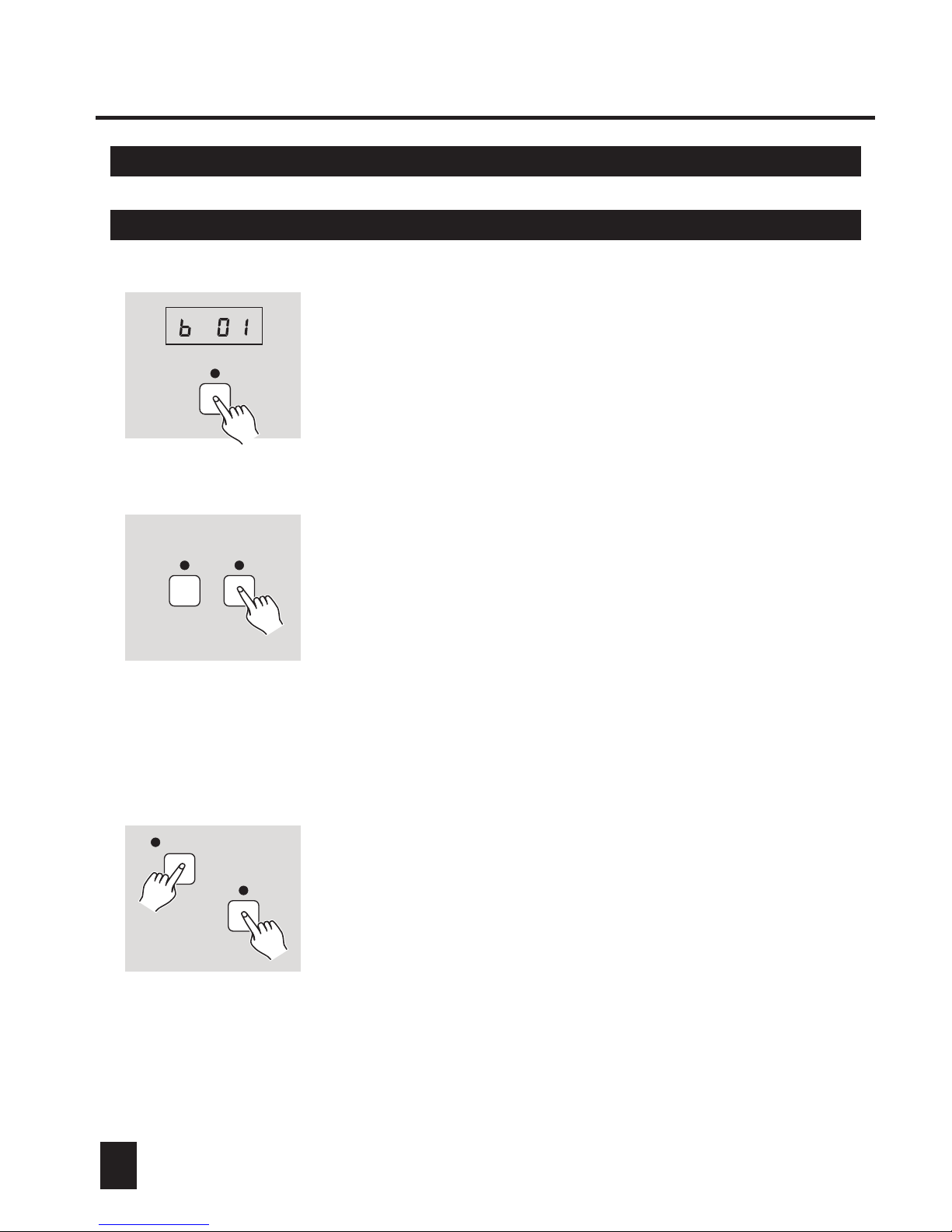
1. Apply power on, the Segment Display reads "bk01",
tap Scene button causing its LED to light or flash.
2. Select the Bank using UP/DOWN button, there are
total 24 banks, each bank can hold up to 40 scenes.
SCENE RECORD
3. Press and hold down Record button, and in the meantime
push Scene/Chase buttons 1, 6, 8, 1,6 and 8 in sequence.
Both Scene and Record LEDs will blinks indicating
record is enabled, and the programmed scenes will be
indicated by the lit LED's.
4. Before you can record scenes, be sure DMX LED on
this unit is flashing. Select or create a scene on your
DMX controller in connection with this unit.
SCENE 1-40
RECORD
5. Keep pressing Record button, tap any of 1-40 buttons
to record the scene into this button, all LED's will flash
3 times briefly indicating this operation.
6. Continue steps 3-4 until you've recorded up to 40
scenes into a bank. Tap Blackout button to go back.
Page 11
2. Operation Guide2. Operation Guide
2.1.2 Delete a scene
8
SCENE RECORD
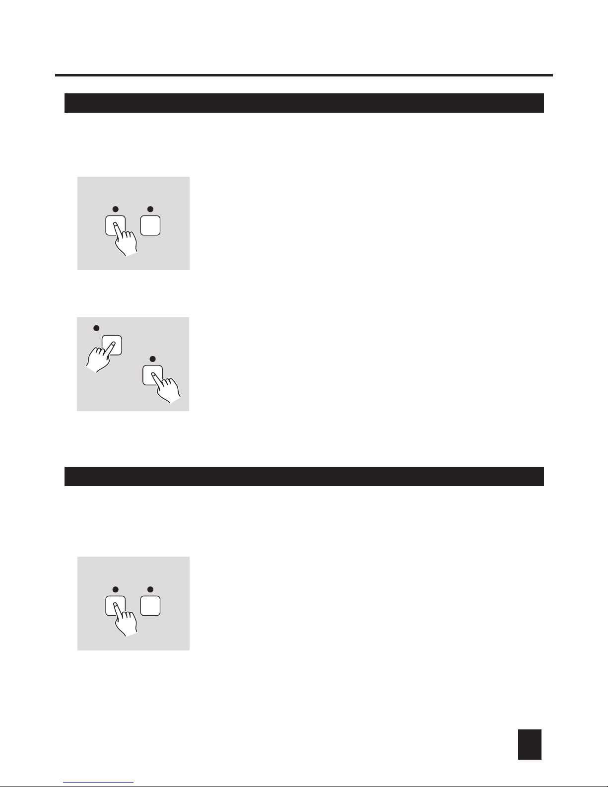
1. Enter Record mode, both Scene and Record LED's
will flash.
2. Tap Scene button again, Record LED will light other
than flash, DMX LED will go out.
3. Use UP/DOWN button to select the Bank containing
the scene you wish to delete.
SCENE 1-40
AUDIO/DEL
4. Keep pressing DEL button, tap one of 1-40 buttons
that holds the scene you wish to delete, all LED's will
flash 3 times briefly indicating this operation.
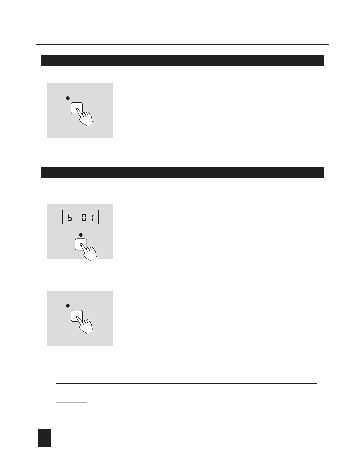
2.1.3 Preview a scene
SCENE RECORD
1. Enter Record mode, both Scene and Record LED's
will flash.
2. Tap Scene button again, Record LED will light other
than flash, DMX LED will go out.
3. Use UP/DOWN button to select the Bank containing
the scene you wish to have a preview.
Page 12
2. Operation Guide2. Operation Guide
9 10
SCENE 1-40
4. Tap one of 1-40 buttons that holds the scene you
want, the LED near this button will flash indicating
a preview of the scene is proceeding.
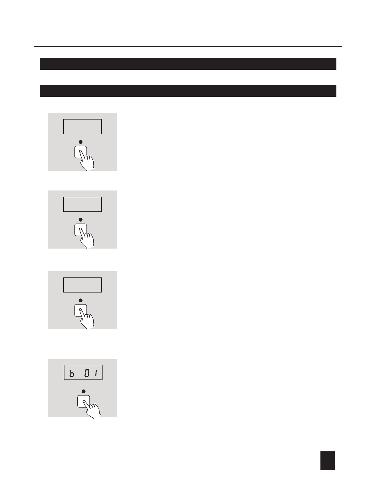
2.2 Playback a Scene
SCENE
K
1. Apply power on, tap Scene button causing its LED
to light or flash.
The LED is lit indicating the scenes will be recalled
instantly. The LED flashes indicating the scenes will
be recalled to fade in or fade out.
2. Use UP/DOWN button to select the bank.
SCENE 1-40
3. Tap one of 1-40 buttons that holds the scene you
wish to playback, the LED near this button is lit indicating
this operation.
4. Tap the button again to go back.
Pressing and holding down the Scene button allows you to access 40-channel
On/off (257-296) mode. Then you can push relevant button to change its On/off
setting. The channel is on if its LED is lit, while the channel is off if its LED
goes out.
Page 13
2.3 Recording Chases2.1.3 Preview a Scene
2. Operation Guide2. Operation Guide
2.3.1 Record Scenes into a Chase
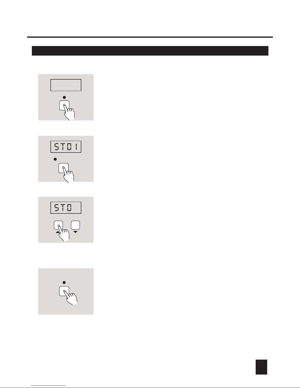
CHASE
1. Apply power on, tap Chase button causing its LED to
light or flash, the Segment Display shows "ST00".
St00
RECORD
CHAS
CHASE
St00
3. Tap one of 1-40 buttons to select a chase, its LED
flashes, the Segment Display shows "ST00" or " ST01".
"ST00" refers to the chase is empty, and "ST01" refer
to the chase contains scenes and the current scene
(the first step) is playing.
SCENE
K
4. Tap Scene button, these three LED's of Scene, Chase
and Record will flash in unison, the Segment Display
shows "bk01" and the scenes recorded in the bank is
indicated by the lit LED's.
2. Press and hold down Record button, and in the mean time push Scene/Chase buttons 1, 6, 8, 1,6 and 8 in
sequence. The Record LED will blinks indicating record
is enabled, in the meantime the Segment display will
read "CHAS" and the programmed chases will be
indicated by the lit LEDs.
Page 14
2. Operation Guide2. Operation Guide
11 12
SCENE 1-40
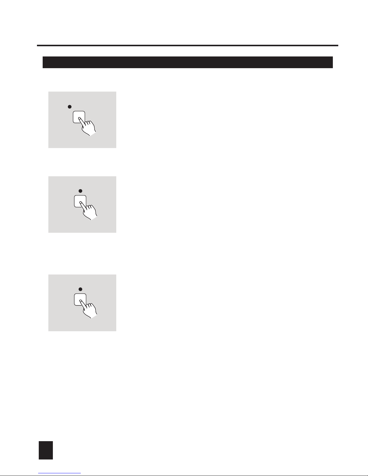
5. Tap one of 1-40 buttons causing its LED to flash,
which means the scene is selected.
RECORD
6. Tap Record button, all LED's will flash briefly three
times indicating the scene has been recorded into
this chase.
7. Continue steps 5-6 until you've recorded up to 99
scenes into this chase.
RECORD
8. Tap Blackout to go back.
Page 15
2.3.2 Delete a step from a Chase2.3.1 Recording Scenes into a Chase
2. Operation Guide2. Operation Guide
1. Enter Record mode, the Segment Display shows
"CHAS".
RECORD
CHAS
CHASE 1-40
AUDIO/DEL
4. Tap AUDIO/DEL button, all LED's shall flash briefly
three times indicating the step has been deleted.
2. Tap one of 1-40 buttons, its LED flashes indicating
this chase is selected, the Segment Display shall
show "ST01'.
3
3. Tap UP/DOWN button to select desired step you
wish to delete.
Page 16
2. Operation Guide2. Operation Guide
2.3.3 Delete a Chase of Scenes 2.4.1 Record steps into a Memory
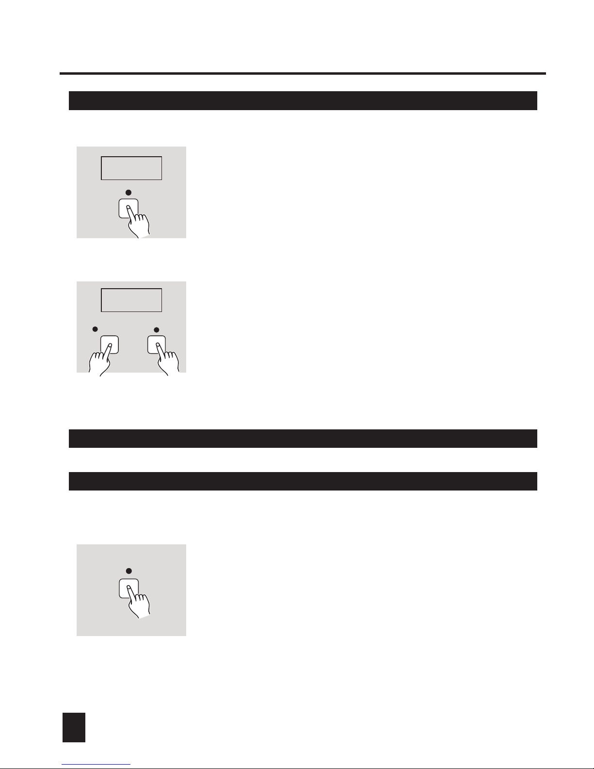
1. Enter Record mode, the Segment Display shows
"CHAS".
RECORD
CHAS
AUDIO/DEL
CHAS
2. Keep pressing AUDIO/DEL button, tap the button
that holds the chase you wish to delete, all LED's
shall flash briefly three times indicating this chase
has been deleted.
CHASE 1-40
2.4 Recording Memories
2.4.1 Record steps into a Memory
CHASE
1. Apply power on, tap Chase button causing its LED
to light or flash.
Page 17
2. Operation Guide2. Operation Guide
1413
RECORD
CHAS
MEMORY 1-8
SCENE 1-40
5. Tap one of 1-40 buttons causing its LED to flash,
which means you've selected the scene.
You may use UP/DOWN button to select the bank
that contains the scene you want.
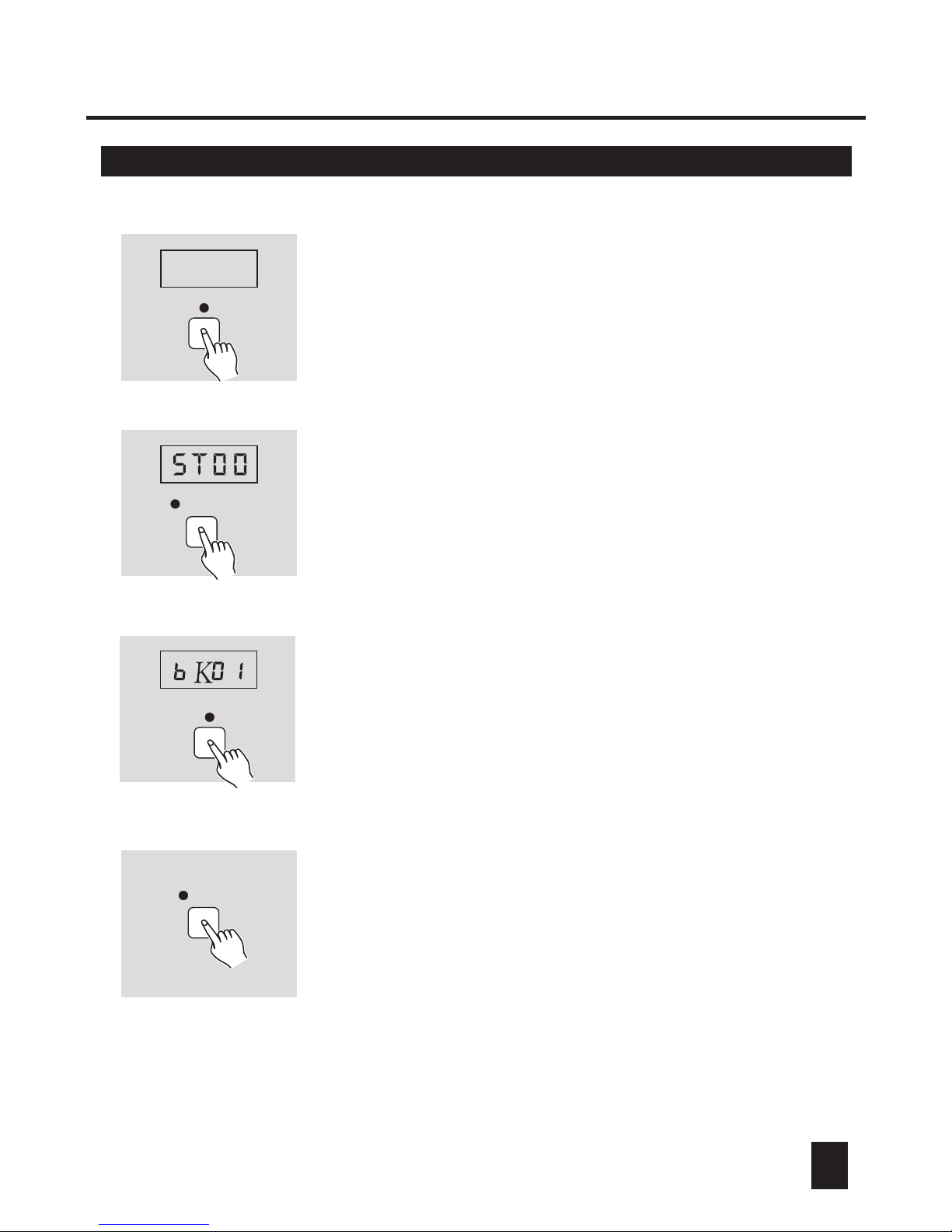
3. Tap the button(Memory 1-8) you wish causing its
LED to flash, the Segment Display shows "ST00"
or "ST01".
"ST00" refers to the Memory is empty, and "ST01"
refers to the Memory contains scenes and the current
scene(the first step) is playing.
SCENE
4. Tap Scene button, these three LED's of Scene, Chase
and Record shall flash in unison, the Segment Display
shows "bk01" and the scenes recorded in the bank is
indicated by their lit LED's.
2.
he Record LED's will flash indicating
recording is active, the Segment Display reads
"CHAS", and the recorded Memories will be indicated
by the lit LED's near them.
Press and hold down Record button, and in the mean time push Scene/Chase buttons 1, 6, 8, 1,6 and 8 in
sequence. T
Page 18
2. Operation Guide2. Operation Guide
2.4.1 Record steps into a Memory
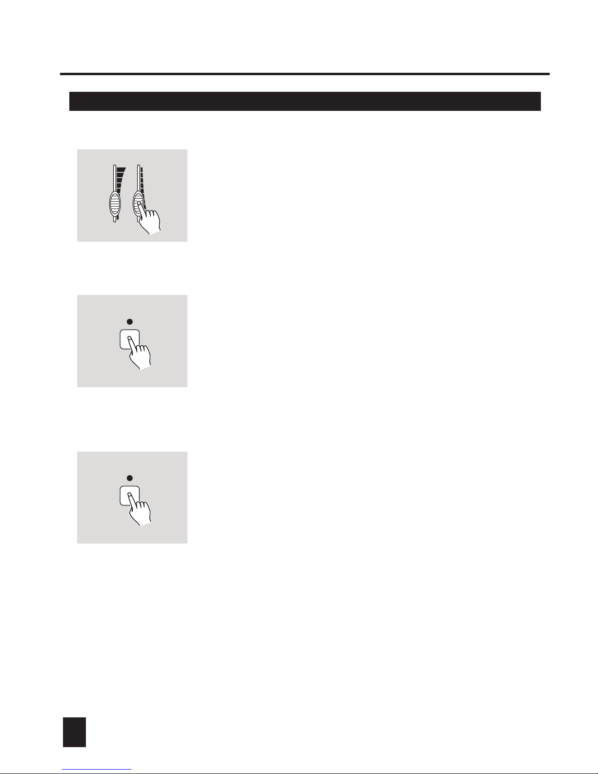
6. Adjust Fade time and Speed slider for the current step.
FADE TIME SPEED
0
2
4
6
8
10 0
2
4
6
8
10
RECORD
7. Tap Record button, all LED's will flash briefly three
times indicating the scene has been recorded into
this Memory.
8. Continue steps 5-7 until you've recorded up to 99
steps into a Memory.
RECORD
9. Tap Blackout to go back step by step.
Page 19
2. Operation Guide2. Operation Guide
2.4.2 Delete a Memory
1615
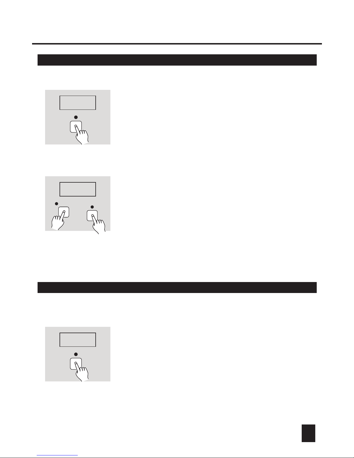
1. Enter Record mode, the Segment Display shows
"CHAS".
RECORD
CHAS
AUDIO/DEL
CHAS
MEMORY 1-8
2. Keep pressing AUDIO/DEL button, tap the button
that holds the Memory you wish to delete, all LED's
shall flash briefly three times indicating the Memory
has been deleted.
(Before you can delete the Memory, be sure that
the Memory has recorded steps.)
2.4.3 Delete a step from a Memory
1. Enter Record mode, the Segment Display shows
"CHAS".
RECORD
CHAS
Page 20
2. Operation Guide2. Operation Guide
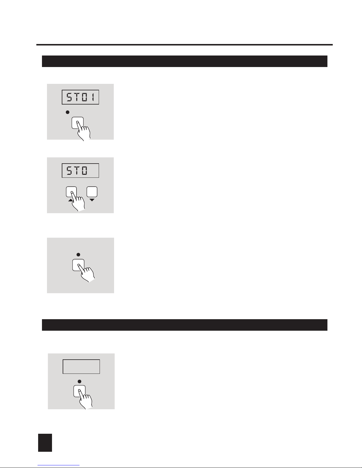
2.4.3 Delete a step from a Memory
MEMORY 1-8
AUDIO/DEL
4. Tap AUDIO/DEL button, all LED's shall flash briefly
three times indicating the step has been deleted.
2. Tap the button(Memory 1-8) you wish, its LED flashes
and the Segment Display reads "ST01".
3
3. Tap UP/DOWN button to select desired step you
wish to delete.
2.4.4 Modify steps of a Memory
1. Enter Record mode, the Segment Display shows
"CHAS".
RECORD
CHAS
Page 21
2. Operation Guide2. Operation Guide
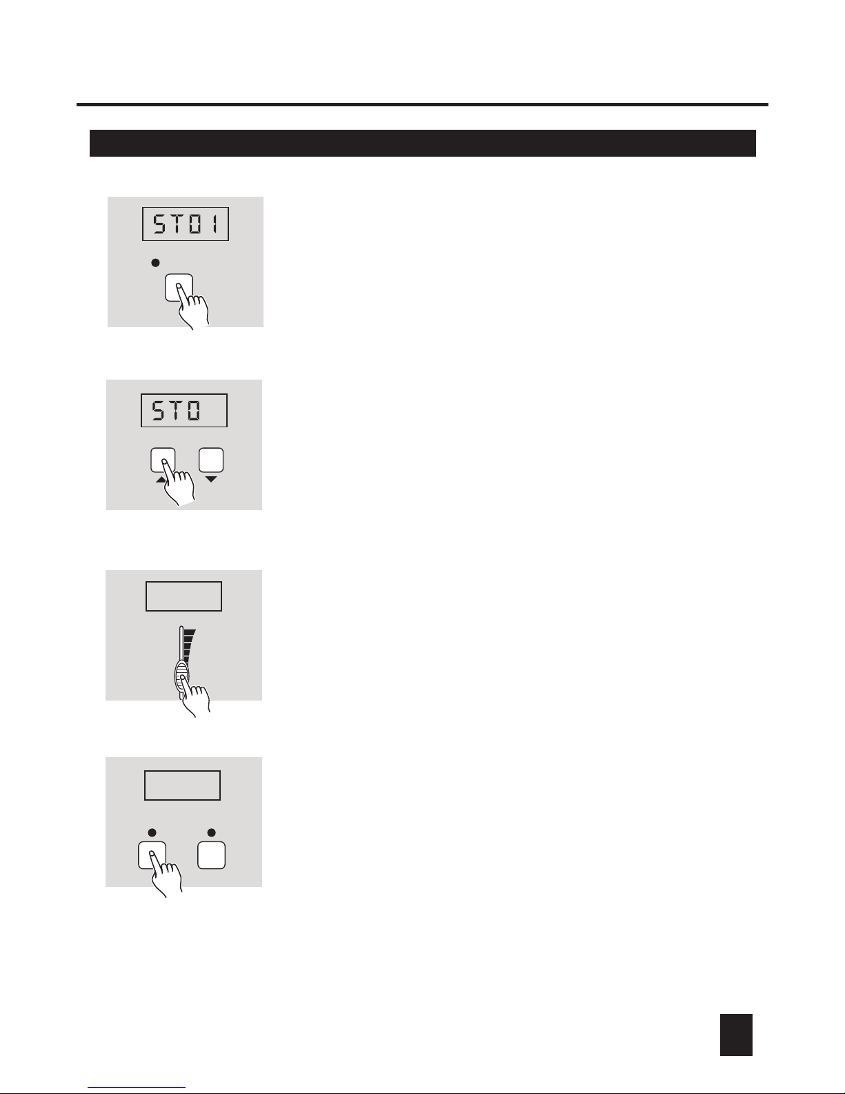
2.4.4 Modify steps of a Memory
1817
MEMORY 1-8
2. Tap the button(Memory 1-8) you wish, its LED flashes
and the Segment Display reads "ST01".
3
3. Tap UP/DOWN button to select desired step you
wish to modify.
FADE TIME
0
2
4
6
8
10
8.00
4. Move Fade time slider to adjust fade time for the
current step from instant to 10 minutes, the Segment
Display shows the fade time.,
8.00
CHASE TAP SYNC
5. Once fade time is satisfactory, tap Chase button,
the Tap Sync LED shall flash.
Page 22
2. Operation Guide2. Operation Guide
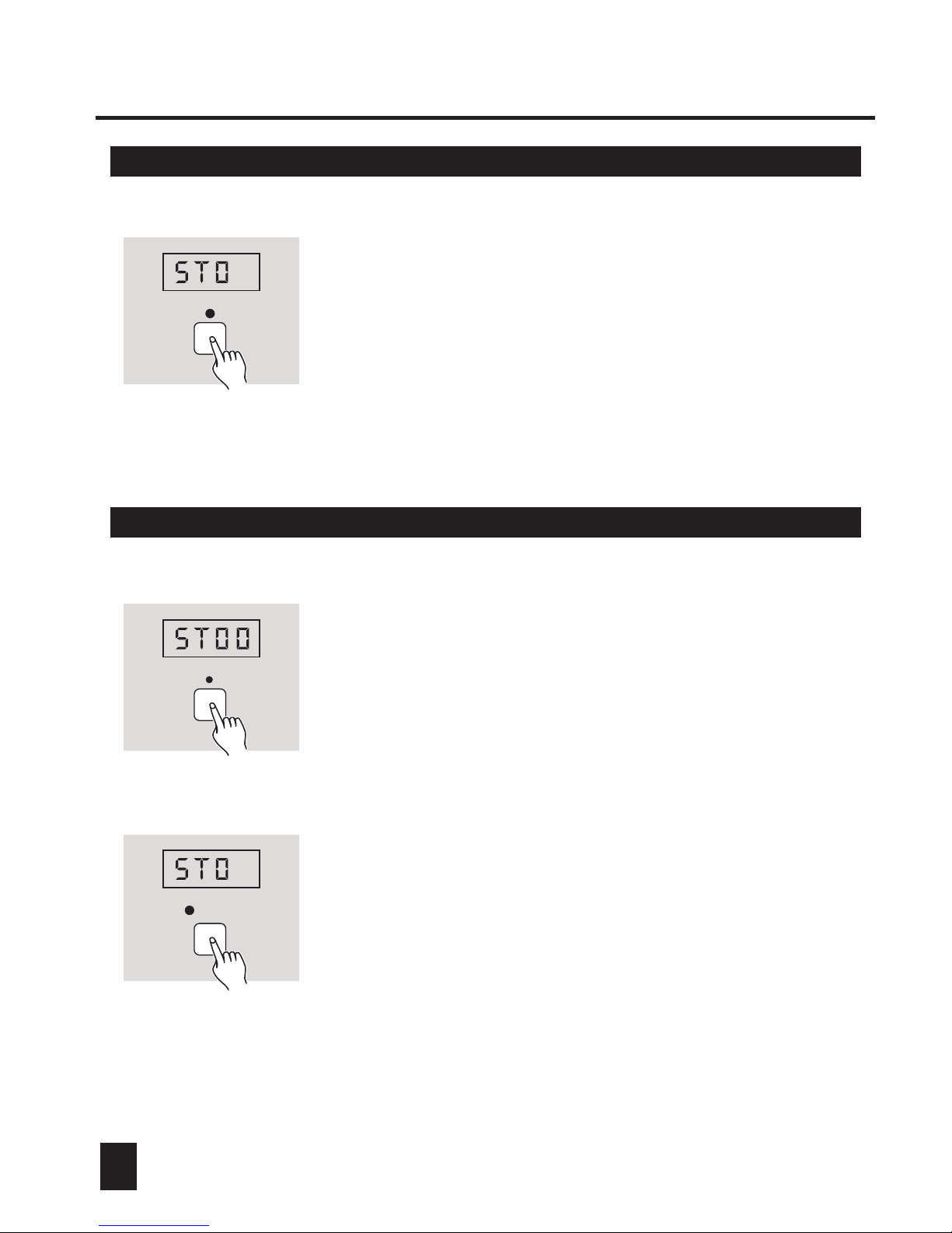
2.4.4 Modify steps of a Memory
3
6. Tap Record button, all LED's shall flash briefly three
times indicating you've changed fade time of the step.
RECORD
7. Tap Blackout button, then you can continue steps 2-6
to change fade time of other steps.
2.5 Playback one or more Chases or Memories
CHASE
1. Apply power on, tap Chase button causing its LED
to light or flash, the Segment Display shows "ST00".
3
CHASE 1-40
2. When Chase LED is lit, only one Chase or Memory
can be selected. Tap one of Chase 1-40 or Memory
1-8 buttons containing scenes, its LED shall be lit
indicating the chase or memory is playing.
Page 23
2. Operation Guide2. Operation Guide
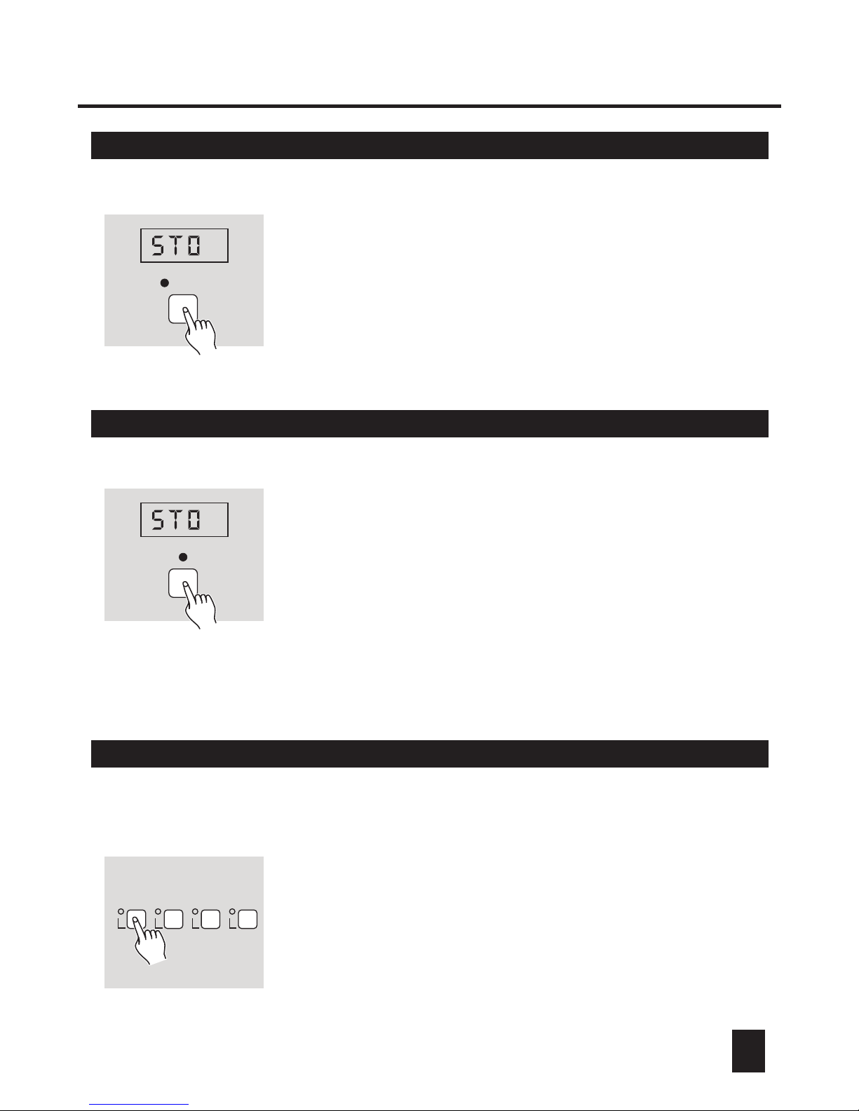
2.5 Playback one or more Chases or Memories
2019
3
CHASE 1-40
3. When Chase LED flashes, two or more Chases or
Memories can be selected at a time. If you select
several Chases or Memories, these Chases or
Memories shall be sequential in the order you
select.
2.6 Audio Chase/Memory
3
AUDIO/DEL
1. When the chase or memory is playing, you may tap
AUDIO/DEL button, its LED is lit, which refers to that
Audio mode is active, the chase or memory shall be
subject to the audio signal detected by built-in Mic.
2. Tap AUDIO/DEL button again causing its LED to go
out, the chase or memory will not be activated by the
audio signal.
2.7 Send Record Data
9 10 11 12
1. You must set up proper DMX connection between two
unit before you can send or receive record data.
2. Turn the power off. While pressing buttons 9, 10, 11,
and 12, turn the power on. If the content of this unit is
empty, the Segment Display shall show "EMPT" . If the
content contains scenes or chases, the Segment
Display shall show "OUT", which means this unit is
ready to send record data.
Page 24
2. Operation Guide2. Operation Guide
2.7 Send Record Data 2.8 Receive Record Data
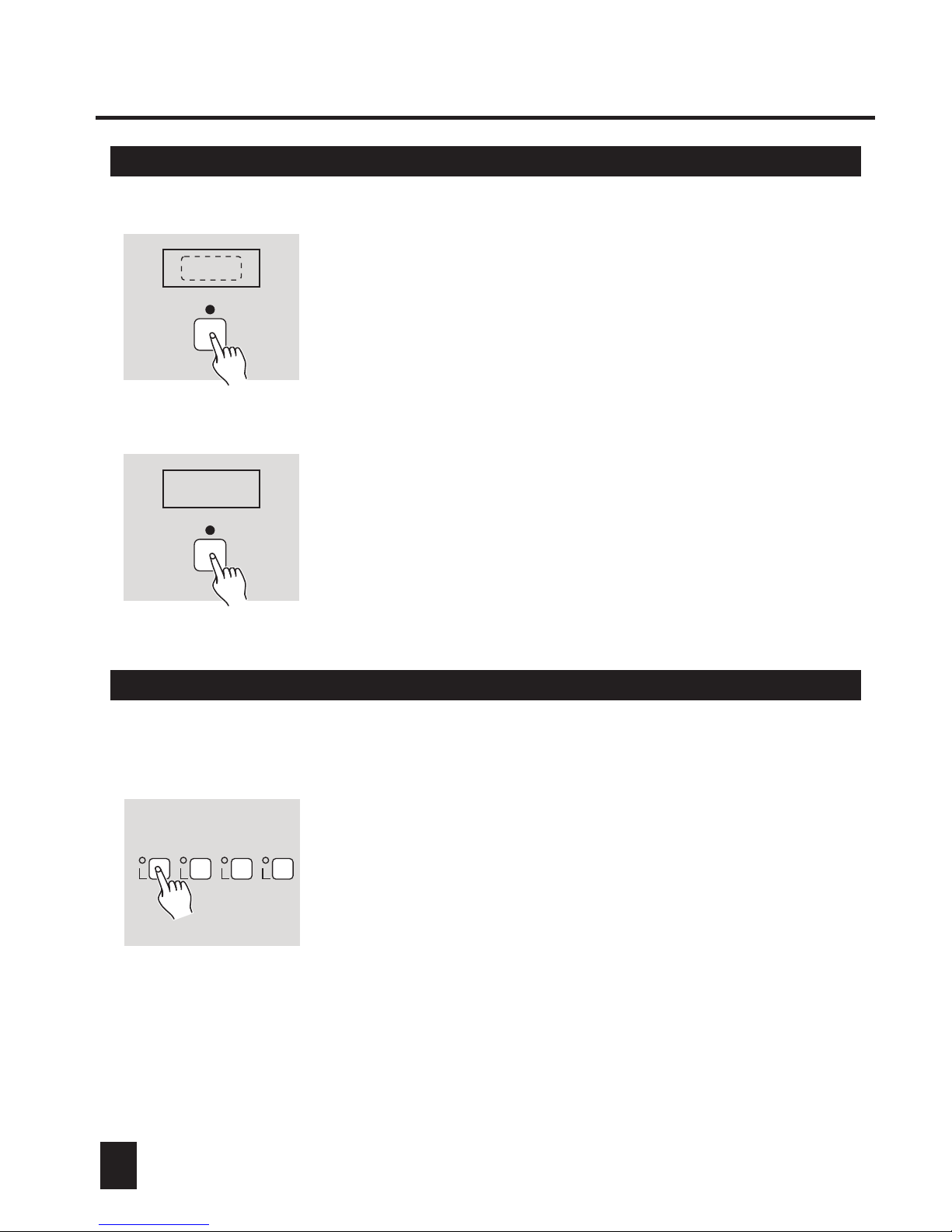
3. Press Scene button to send record data. Now, any
buttons doesn't work until the Segment Display
shows "End".
SCENE
4. When the Segment Display shows "End", tap
Blackout button to go back.
BLACKOUT
END
2.8 Receive Record Data
17 18 19 20
1. Turn the power off.
2. While pressing buttons 17, 18, 19, and 20, turn the
power on.
If the content of this unit contains scenes or chases,
the Segment Display shall show "SURE" to remind
whether or not to overwrite the exited scenes or chases.
If you are sure, you may tap Scene button to receive
record data from another unit. If not, just tap Blackout
button to go back.
1. When Master LED is lit , this unit will serve as the Master unit, and the other units
connected will be slaves to this master unit. When Master LED blinks, this unit will
be deprived from this linkup, i.e. Stand alone. Whether the Master LED is lit or blinks,
DMX addresses within 001-296 are available for this unit.
2. When Slave 1 LED is lit , this unit will serve as the Slave unit and no Master unit exists
in the linkup. Slave
1 LED blinks, this unit will serve as the Slave unit and will be subject to the Master unit.
3. When Slave 2 LED is lit, this unit will serve as the Slave unit and no Master unit exists.
When Slave 2 LED blinks, this unit will serve as the Slave unit and will be subject to
the Master unit in the linkup. Meantime,
for this unit.
You can move the slider on the rear to select among Master, Slave 1 and
Slave 2 mode
Page 25
2. Operation Guide2. Operation Guide
2221
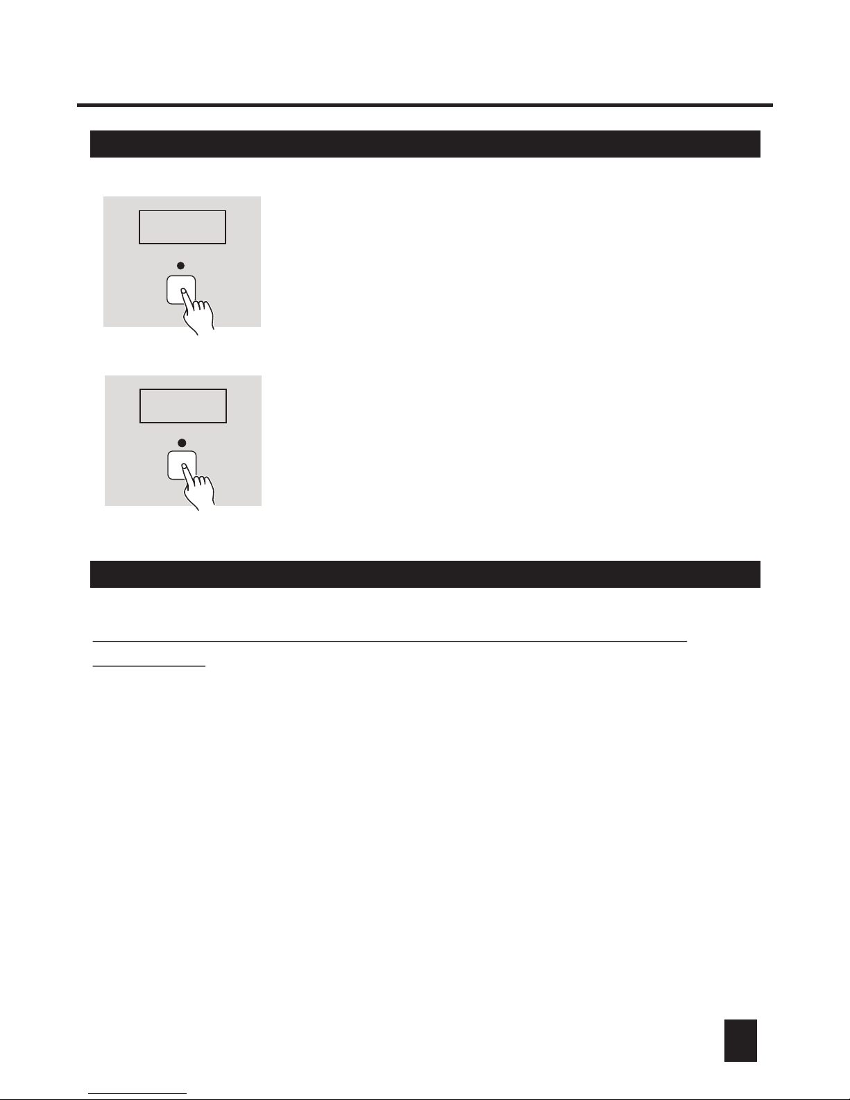
SCENE
3. Before you can receive, be sure another unit has always
been in "SEND" mode. Press Scene button to receive
record data, the Segment Display shall show "IN"
indicating this unit is receiving file data. Any button
doesn't work until the Segment Display shows "End".
IN
BLACKOUT
END
4. When the Segment Display shows "End", tap the
Blackout button to go back.
2.9 Master /Slave 1 /Slave 2 Mode
1. When Master LED is lit , this unit will serve as the Master unit, and the other units
connected will be slaves to this master unit. When Master LED blinks, this unit will
be deprived from this linkup, i.e. Stand alone. Whether the Master LED is lit or blinks,
DMX addresses within 001-296 are available for this unit.
2. When Slave 1 LED is lit , this unit will serve as the Slave unit and no Master unit exists
in the linkup. Slave
1 LED blinks, this unit will serve as the Slave unit and will be subject to the Master unit.
3. When Slave 2 LED is lit, this unit will serve as the Slave unit and no Master unit exists.
When Slave 2 LED blinks, this unit will serve as the Slave unit and will be subject to
the Master unit in the linkup. Meantime,
DMX addresses within 001-296 are available for this unit. When the
DMX addresses within 001-256 are available for this unit.
DMX addresses within 257-512 are available
for this unit.
You can move the slider on the rear to select among Master, Slave 1 and
Slave 2 mode
Page 26

Technical Specifications
Power Input ...................................................... DC 9V, 500 mA min.
DMX Output .............................................. 3 pin female XLR socket
DMX Input .................................................... 3 pin male XLR socket
Link Out ..................................................... 5 pin female XLR socket
Link In ........................................................... 5 pin male XLR socket
Audio Input .................................................... By built-in microphone
Accessory ........................................................AC/DC Adaptor x1PC
Dimensions .............................................................. 482x132x73mm
Weight(excluding adaptor) ............................................ Appro. 2.2 kg
23
2. Operation Guide
2.10 Blackout Access Setting
This unit allows you to access Blackout or not when power-on.
Disconnect the power firstly. Hold down Scene/ Chase 33, 34, 35 and 36
button, and in the meantime apply the power on. Then you can push
Tap Sync button to change between " Y-BO" and "N-BO" modes.
If the Segment display reads "Y-BO", this unit will access Blackout once the
power is on. If the Segment display reads "N-BO", this unit won't access
Blackout directly when power is on.
You can push Blackout button to go out of this setting.
Page 27

Technical Specifications
Power Input ...................................................... DC 9V, 500 mA min.
DMX Output .............................................. 3 pin female XLR socket
DMX Input .................................................... 3 pin male XLR socket
Link Out ..................................................... 5 pin female XLR socket
Link In ........................................................... 5 pin male XLR socket
Audio Input .................................................... By built-in microphone
Accessory ........................................................AC/DC Adaptor x1PC
Dimensions .............................................................. 482x132x73mm
Weight(excluding adaptor) ............................................ Appro. 2.2 kg
24
Page 28

Rev 2.3
Printed in PR China
All Rights Reserved!
24-004-0952
R
 Loading...