

Page 1

DM-2512
DMX manager
User manual
Page 2

Musikhaus Thomann
Thomann GmbH
Hans-Thomann-Straße 1
96138 Burgebrach
Germany
Telephone: +49 (0) 9546 9223-0
E-mail: [email protected]
Internet: www.thomann.de
27.12.2018, ID: 172666 (V2)
Page 3

Table of contents
1 General information................................................................................................................................. 6
1.1 Further information........................................................................................................................... 7
1.2 Notational conventions.................................................................................................................... 8
1.3 Symbols and signal words............................................................................................................... 9
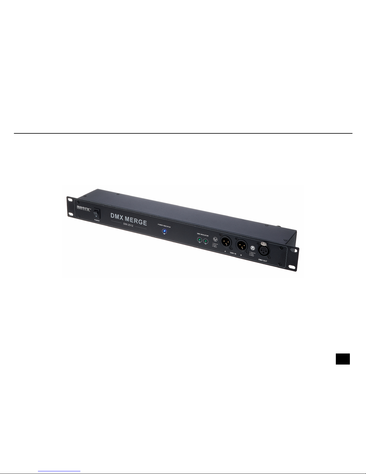
2 Safety instructions.................................................................................................................................. 11
2.1 Safety instructions........................................................................................................................... 11
3 Features....................................................................................................................................................... 15
4 Installation and starting up................................................................................................................ 16
5 Connections and controls................................................................................................................... 19
6 Operating.................................................................................................................................................... 23
6.1 Setting the operating modes....................................................................................................... 23
6.2 Setting the DMX address............................................................................................................... 26
7 Technical specications....................................................................................................................... 28
8 Plug and connection assignments.................................................................................................. 29
Table of contents
DM-2512
3
DMX manager
Page 4

9 Protecting the environment.............................................................................................................. 30
Table of contents
4
DM-2512
DMX manager
Page 5
DM-2512
5
DMX manager
Page 6

1 General information
This manual contains important instructions for the safe operation of the unit. Read and follow
the safety instructions and all other instructions. Keep the manual for future reference. Make
sure that it is available to all those using the device. If you sell the unit please make sure that
the buyer also receives this manual.
Our products are subject to a process of continuous development. Thus, they are subject to
change.
General information
6
DM-2512
DMX manager
Page 7
1.1 Further information
On our website (www.thomann.de) you will nd lots of further information and details on the
following points:
Download This manual is also available as PDF le for you to download.
Keyword search
Use the search function in the electronic version to nd the topics of
interest for you quickly.
Online guides
Our online guides provide detailed information on technical basics
and terms.
Personal consultation For personal consultation please contact our technical hotline.
Service
If you have any problems with the device the customer service will
gladly assist you.
General information
DM-2512
7
DMX manager
Page 8

1.2 Notational conventions
This manual uses the following notational conventions:
The letterings for connectors and controls are marked by square brackets and italics.
Examples: [VOLUME] control, [Mono] button.
The individual steps of an instruction are numbered consecutively. The result of a step is
indented and highlighted by an arrow.
Example:
1. Switch on the device.
2. Press [Auto].
ð
Automatic operation is started.
3. Switch o the device.
Letterings
Instructions
General information
8
DM-2512
DMX manager
Page 9
1.3 Symbols and signal words
In this section you will nd an overview of the meaning of symbols and signal words that are
used in this manual.
Signal word Meaning
DANGER! This combination of symbol and signal word indicates an
immediate dangerous situation that will result in death or
serious injury if it is not avoided.
NOTICE! This combination of symbol and signal word indicates a pos‐
sible dangerous situation that can result in material and
environmental damage if it is not avoided.
Warning signs Type of danger
Warning – high-voltage.
General information
DM-2512
9
DMX manager
Page 10
Warning signs Type of danger
Warning – danger zone.
General information
10
DM-2512
DMX manager
Page 11

2 Safety instructions
2.1 Safety instructions
This device is intended for merging multiple DMX signals, for distributing one DMX signal to
multiple DMX chains and for the extension of a DMX chain. Use the device only as described in
this user manual. Any other use or use under other operating conditions is considered to be
improper and may result in personal injury or property damage. No liability will be assumed for
damages resulting from improper use.
This device may be used only by persons with sucient physical, sensorial, and intellectual
abilities and having corresponding knowledge and experience. Other persons may use this
device only if they are supervised or instructed by a person who is responsible for their safety.
Intended use
Safety instructions
DM-2512
11
DMX manager
Page 12
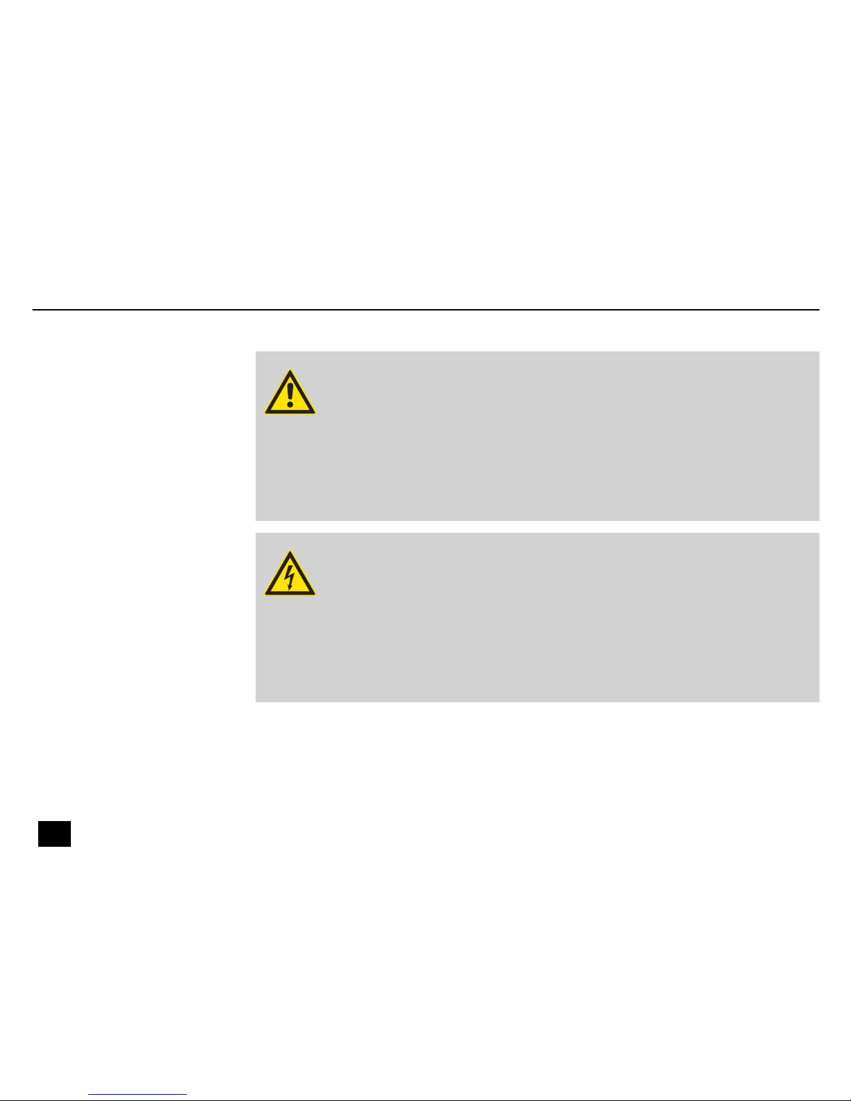
DANGER!
Danger for children
Ensure that plastic bags, packaging, etc. are disposed of properly and are not
within reach of babies and young children. Choking hazard!
Ensure that children do not detach any small parts (e.g. knobs or the like) from
the unit. They could swallow the pieces and choke!
Never let children unattended use electrical devices.
DANGER!
Electric shock caused by high voltages inside
Within the device there are areas where high voltages may be present. Never
remove any covers.
There are no user-serviceable parts inside.
Do not use the device if covers, protectors or optical components are missing or
damaged.
Safety
Safety instructions
12
DM-2512
DMX manager
Page 13
NOTICE!
Risk of re
Do not block areas of ventilation. Do not install the device near any direct heat
source. Keep the device away from naked ames.
NOTICE!
Operating conditions
This device has been designed for indoor use only. To prevent damage, never
expose the device to any liquid or moisture. Avoid direct sunlight, heavy dirt, and
strong vibrations.
Safety instructions
DM-2512
13
DMX manager
Page 14

NOTICE!
External power supply
The device is powered by an external power supply. Before connecting the
external power supply, ensure that the input voltage (AC outlet) matches the
voltage rating of the device and that the AC outlet is protected by a residual cur‐
rent circuit breaker. Failure to do so could result in damage to the device and pos‐
sibly the user.
Unplug the external power supply before electrical storms occur and when the
device is unused for long periods of time to reduce the risk of electric shock or
re.
Safety instructions
14
DM-2512
DMX manager
Page 15

3 Features
DMX manager with the following features:
n Four operating modes: HTP, Backup, Merge and LTP
n 2 × 3-pin DMX input on the front panel, 2 × 3-pin DMX input on the rear panel (not usable
in parallel)
n 1 × 3-pin DMX output on the front panel, 1 × 3-pin DMX output on the rear panel (not
usable in parallel)
n 19" rack-mountable
Features
DM-2512
15
DMX manager
Page 16
4 Installation and starting up
Unpack and check carefully there is no transportation damage before using the unit. Keep the
equipment packaging. To fully protect the product against vibration, dust and moisture during
transportation or storage use the original packaging or your own packaging material suitable
for transport or storage, respectively.
Create all connections while the device is o. Use the shortest possible high-quality cables for
all connections. Take care when running the cables to prevent tripping hazards.
NOTICE!
Possible data transmission errors
For error-free operation make use of dedicated DMX cables and do not use ordi‐
nary microphone cables.
Never connect the DMX input or output to audio devices such as mixers or ampli‐
ers.
Installation and starting up
16
DM-2512
DMX manager
Page 17
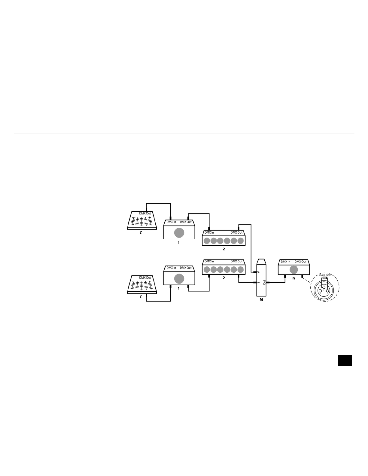
Connect the output of the rst DMX device to the input of the second one and so on, to form a
series connection. Connect the output of this DMX chain to input A on the front or back of the
DMX Manager. Connect the output of a second DMX chain to input B on the front or back of
the DMX Manager. Connect the output on the front or rear of the DMX Manager to the DMX
input of a DMX controller or other DMX device. Make sure that the output of the last DMX
device in the chain is terminated by a resistor (110 Ω, ¼ W). Note that the ports on the front
and back can not be used in parallel.
Connections in ‘DMX’ mode
Installation and starting up
DM-2512
17
DMX manager
Page 18

When the device and the DMX controller are operational, the DMX indicator in the display
shows that a DMX signal is being received on the input.
The unit has been designed for rack mounting in a standard 19" rack; it occupies one rack unit.
DMX indicator
Rack mounting
Installation and starting up
18
DM-2512
DMX manager
Page 19
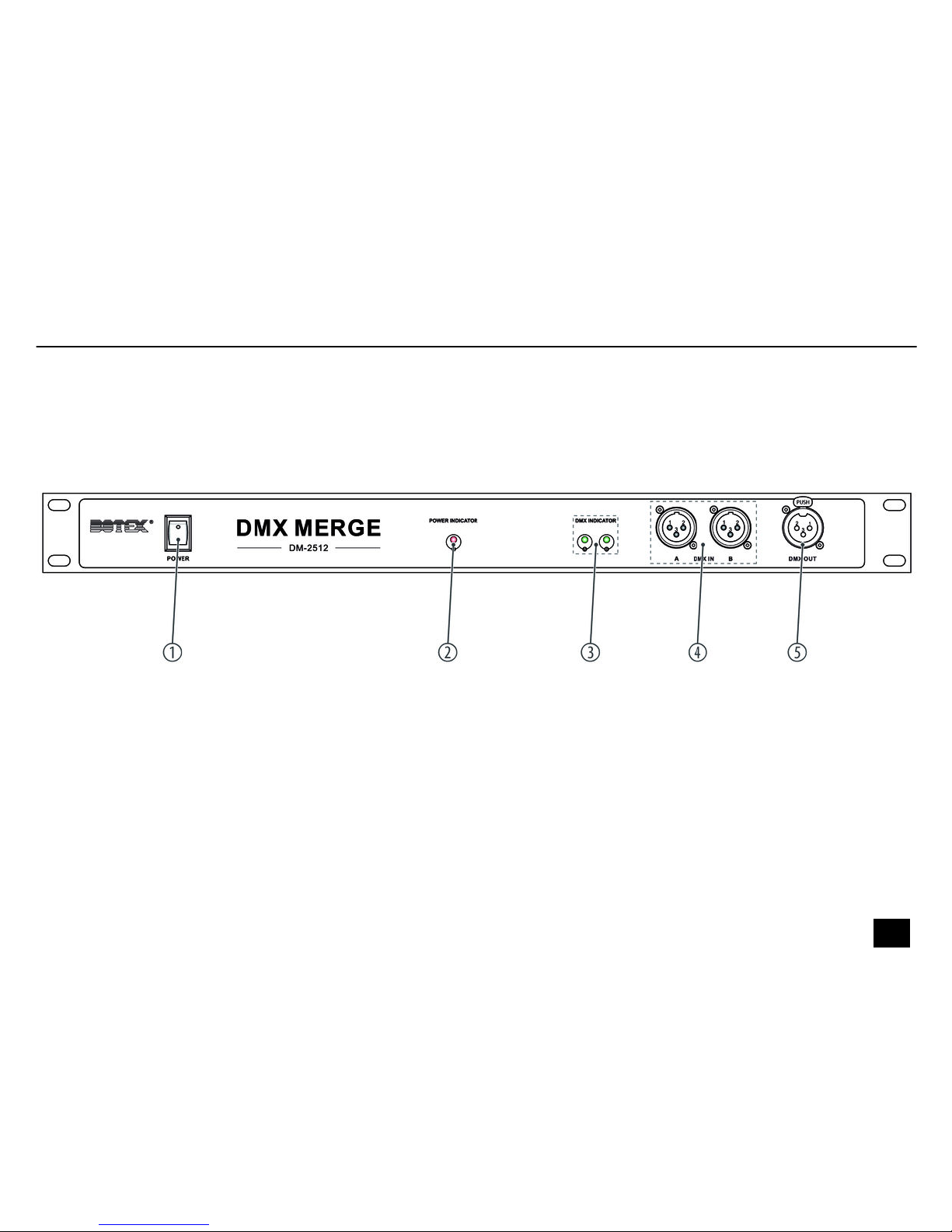
5 Connections and controls
Front panel
Connections and controls
DM-2512
19
DMX manager
Page 20
1 [POWER]
Main switch. Turns the device on and o.
2 [POWER INDICATOR]
Indicator LED for operating status. Lights up once the device is turned on.
3 [DMX INDICATOR] [A], [B]
2 × indicator LED for DMX input. The indicator LED of the respective channel lights up green as soon as a signal is
present.
4 [DMX IN]
2 × DMX input, designed as XLR socket
5 [DMX OUT]
1 × DMX output, designed as XLR socket
Connections and controls
20
DM-2512
DMX manager
Page 21
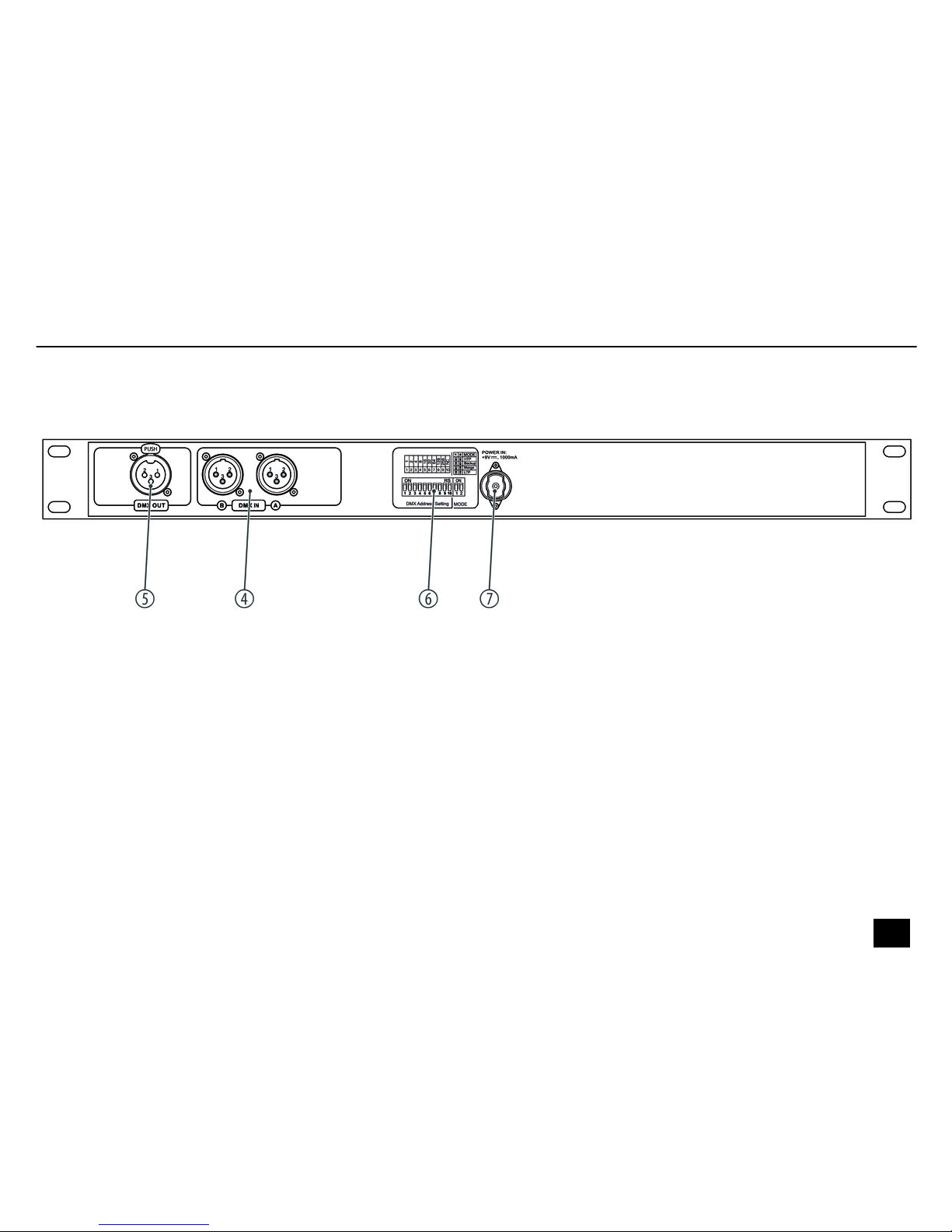
Rear panel
Connections and controls
DM-2512
21
DMX manager
Page 22
4 [DMX IN]
2 × DMX input, designed as XLR socket
5 [DMX OUT]
1 × DMX output, designed as XLR socket
6 DIP switches for setting the operating modes and DMX addresses
7 Connection for the plug-in power supply.
Connections and controls
22
DM-2512
DMX manager
Page 23

6 Operating
6.1 Setting the operating modes
The device oers four dierent operating modes for combining several DMX signals: HTP,
Backup, Merge and LTP.
In HTP mode, the highest DMX value has priority.
Set DIP switches 1 and 2 to [ON].
ð
The HTP mode is activated. If two DMX signals are present at the inputs of the
device, then the signal with the higher value overwrites the other signal.
In BACKUP mode, the signal of the other input is accepted if no DMX signal is present at one
input.
Operating mode HTP (High Take
Precedence Modus)
Operating mode BACKUP
Operating
DM-2512
23
DMX manager
Page 24
Set DIP switch 1 to [OFF] and switch 2 to [ON].
ð
The BACKUP mode is activated. If a DMX signal is present at input A, it is output at
the device output. If no DMX signal is present at input A, then the signal from input
B is output at the device output.
In MERGE mode, the DMX signals A and B are combined to form a new signal.
1. Set DIP switch 1 to [ON] and switch 2 to [OFF].
ð
The MERGE mode is activated.
2. Use the DIP switches 1 … 9 to set the DMX start address for the merged new signal.
Example: You want to merge the rst 6 channels of DMX signal A and all subsequent channels
of DMX signal B.
1. Set DIP switches 1, 2 and 3 to [OFF].
2. Set DIP switches 4 … 10 to [ON].
ð
The rst 6 channels of the DMX output signal are occupied by the 6 channels of the
DMX signal A. The channels 7 … 512 of the DMX output signal are occupied by the
channels of the DMX signal B.
Operating mode MERGE
Operating
24
DM-2512
DMX manager
Page 25

In LTP mode, the last DMX value has priority.
Set DIP switches 1 and 2 to [OFF].
ð
The LTP mode is activated. If two DMX signals are present at the inputs of the device,
then the last two changed values are applied.
Operating mode LTP (Latest
Takes Precedence)
Operating
DM-2512
25
DMX manager
Page 26
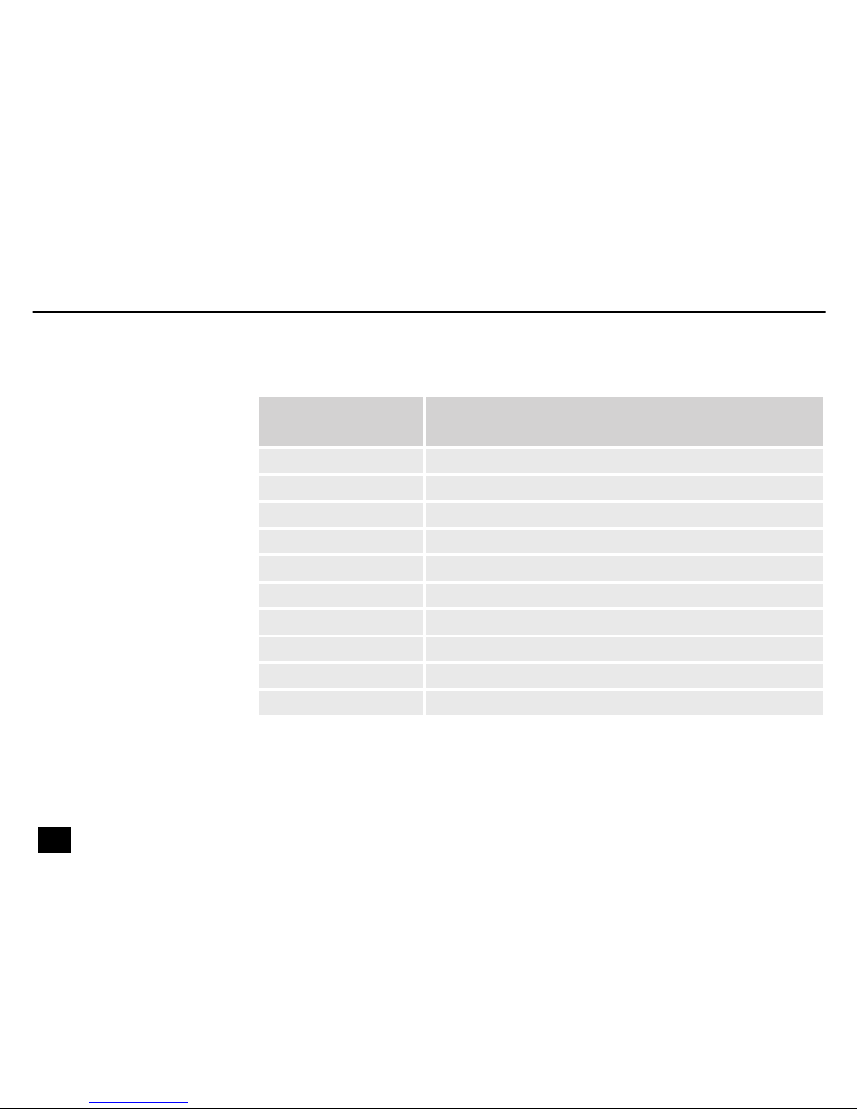
6.2 Setting the DMX address
DMX B
Start channel number
Dip switch ON
1 1
2 2
3 1, 2
4 3
5 1, 3
6 2, 3
7 1, 2, 3
8 4
9 1, 4
10 2, 4
DMX address table
Operating
26
DM-2512
DMX manager
Page 27
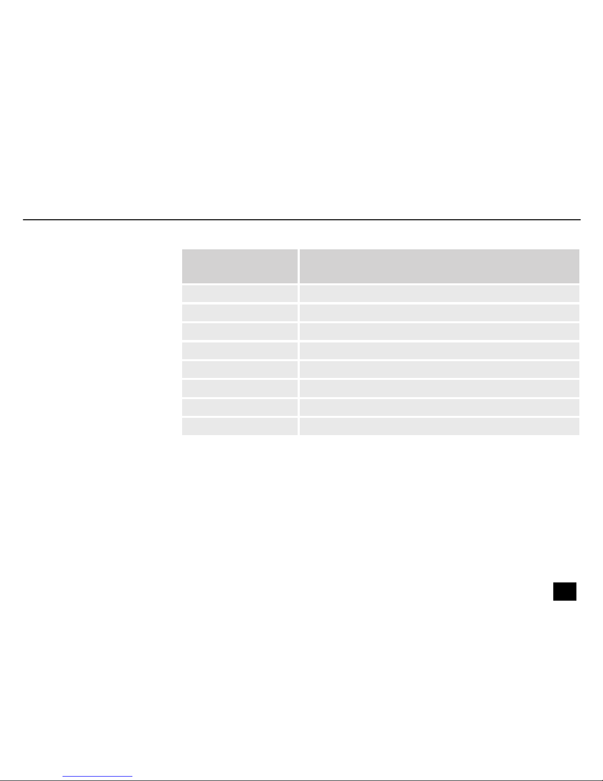
DMX B
Start channel number
Dip switch ON
11 1, 2, 4
12 3, 4
13 1, 3, 4
14 2, 3, 4
15 1, 2, 3, 4
16 5
… …
511 1, 2, 3, 4, 5, 6, 7, 8, 9
Operating
DM-2512
27
DMX manager
Page 28
7 Technical specications
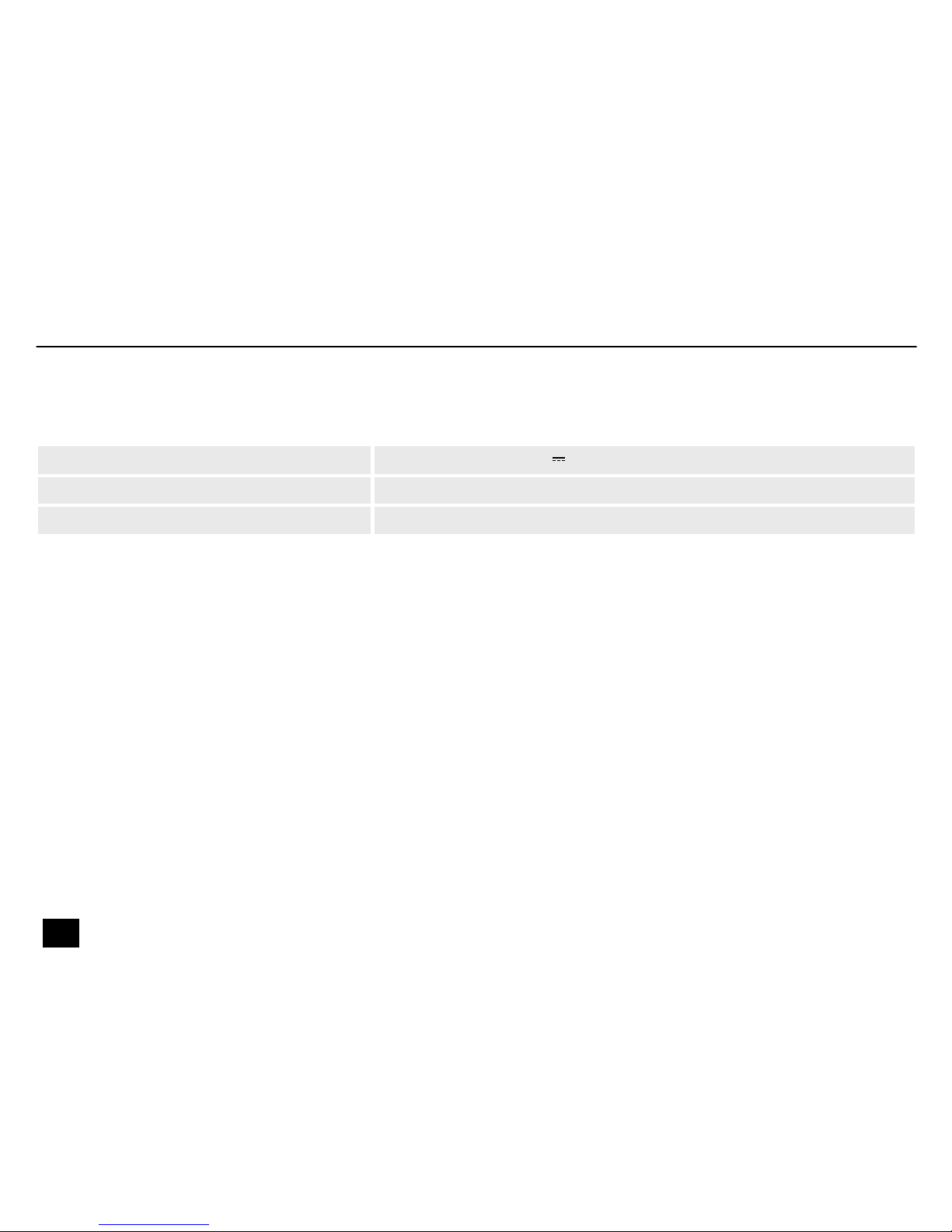
Voltage supply
Plug-in power supply (9 V / 1000 mA , centre positive)
Dimensions (W × H × D) 482 mm × 44 mm × 162 mm
Weight 2.0 kg
Technical specications
28
DM-2512
DMX manager
Page 29
8 Plug and connection assignments
This chapter will help you select the right cables and plugs to connect your valuable equip‐
ment so that a perfect light experience is guaranteed.
Please take our tips, because especially in ‘Sound & Light’ caution is indicated: Even if a plug
ts into a socket, the result of an incorrect connection may be a destroyed DMX controller, a
short circuit or ‘just’ a not working light show!
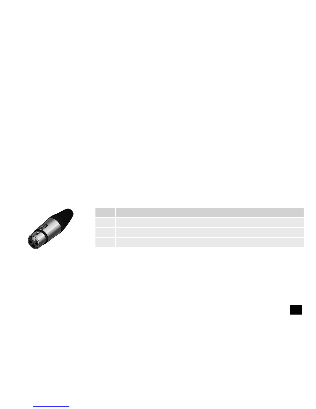
The unit oers a 3-pin XLR socket for DMX output and a 3-pin XLR plug for DMX input. Please
refer to the drawing and table below for the pin assignment of a suitable XLR plug.
Pin Conguration
1 Ground, shielding
2 Signal inverted (DMX–, ‘cold signal’)
3 Signal (DMX+, ‘hot signal’)
Introduction
DMX connections
Plug and connection assignments
DM-2512
29
DMX manager
Page 30
9 Protecting the environment
For the transport and protective packaging, environmentally friendly materials have been
chosen that can be supplied to normal recycling.
Ensure that plastic bags, packaging, etc. are properly disposed of.
Do not just dispose of these materials with your normal household waste, but make sure that
they are collected for recycling. Please follow the notes and markings on the packaging.
This product is subject to the European Waste Electrical and Electronic Equipment Directive
(WEEE) in its currently valid version. Do not dispose with your normal household waste.
Dispose of this device through an approved waste disposal rm or through your local waste
facility. When discarding the device, comply with the rules and regulations that apply in your
country. If in doubt, consult your local waste disposal facility.
Disposal of the packaging mate‐
rial
Disposal of your old device
Protecting the environment
30
DM-2512
DMX manager
Page 31

Page 32

Musikhaus Thomann · Hans-Thomann-Straße 1 · 96138 Burgebrach · Germany · www.thomann.de
 Loading...