

Page 1
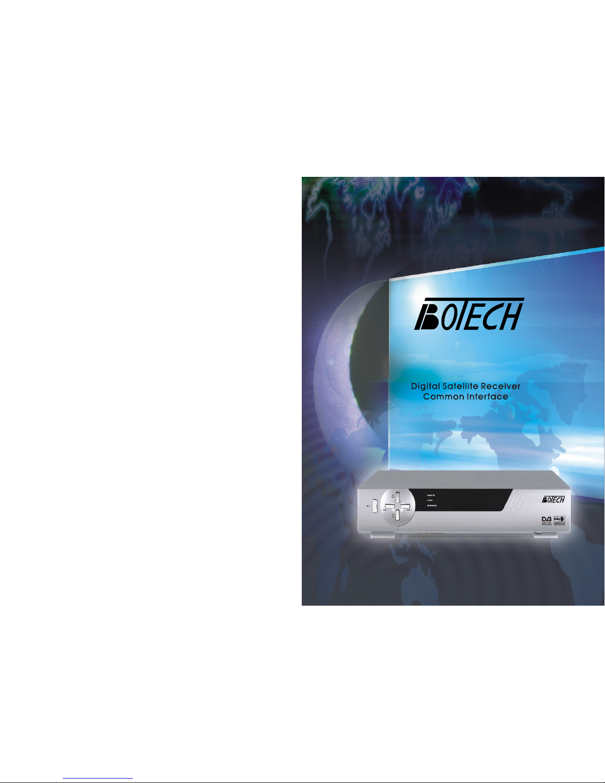
Digital Satellite Receiver with Common Interface
CA 9500 IR/CA 9500 IRCI
Page 2
Safety Instructions
Be sure to read this User's Manual before starting the operation of the receiver
Never open the cover.
It is dangerous to touch the inside of the receiver due to possible electric hazard.
Do not use a damaged power cord that may cause a fire or an electric shock.
When the receiver is unused for a long time, unplug the power cord from the wall outlet.
Do not touch a power cord with wet hand. It may cause an electric shock.
Place the receiver in well ventilated and no-heat environment.
When connecting cables, the receiver must have been powered off.
Do not stack the exposed firing device, such as candle, on top of the receiver.
Do not expose the receiver to dripping or splashing and that no objects filled with
liquids, such as vase, shall be placed on the apparatus.
Do not plug in/out CI module, when the receiver is powered on.
But you can insert smart card to CI module with powered on.
How to Use This Manual
This manual provides complete instructions for installing and using this receiver.
The following symbols will serve as follow.
Indicates a warning information.
Indicates any other additional important or helpful information.
Represents a button on the remote controller or the receiver.
Represents a menu item within a window.
MENU
(Bold Character)
Move to
(Italic Character)
Tips
Warning
1
Page 3
Contents
Safety Instructions
1. Before You Begin
1.1 Features
1.2 Accessories
2.Controls and Functions
2.1 Front Panel
3.Connections
3.1 Connecting to TV & VCR
3.2 Connecting to Dish
3.3 Connecting to CI Module
4.Setting and Operations
4.1 Before Settings
4.2 Basic Settings
4.3 Viewing TV(or Radio)
4.4 EPG
4.5 Channels Manager
4.6 Add Favorites
4.7 Favorites Manager
4.8 Other Settings
4.9 Name Edit
Connections
A.1 Trouble Shooting
A.2 Specifications
A.3 Glossary of Terms.
3.4 Connecting to SMART CARD Module
2.2 Remote Control Unit
2.3 Rear Panel
<Irdeto Embeded>
1 Slot Smart Card
Features
1.1 Features
<Common Part>
Easy Graphic MENU Interface
RS232C Port for Updating Control Software and Additional Service
Supports DiSEqC1.0/1.2, 0/12V, 13/18V, 22Khz Tone
2-SCART Connectors & 1-RCA Connector
Multi-language Function(Menu, Audio)
Last Channel Memory
OSD : Transparency & Blending, 256Palette Colors
Front Panel Buttons & IR Remote Controller User Interface
Editing Functions(TV or Radio Channel, Channel Name, Favorite Name,
Satellite Name)
EPG for On Screen Channel Information
Channels Memory for Multi-satellite(up to 64)
3 Operation Modes(Digital TV, Digital Radio, Favorite)
PLL RF Modulator UHF21-69 with PAL G/I/K(optional)
<Digital Part>
Receives QPSK Satellite Broadcasting RF Signal and Decodes the Digitally
Encoded Signal
SCPC/MCPC Receivable from C/KU-band Satellite.
Digital Tuner with Loop-through out
MPEG-2 Main Profile at Main Level
Teletext Supported Through VBI & OSD
4900 Channels Memory
<CI Part>(CI Model Only)
DVB Common Interface(Viaccess, Nagra Vision, Conax, Irdeto, Cryptoworks,
ASTON)
2
3
Page 4
Accessories
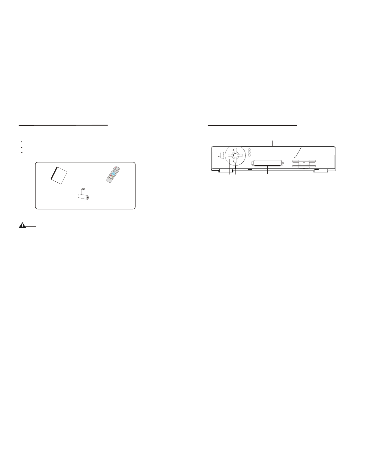
1.2 Accessories
User's Manual
Remote Control Unit
Batteries
Please don't recharge, disassemble, electric short, and mix with used or other
battery types
Figure 1. Accessories
Warning
U
s
e
r
'
s
Ma
n
u
a
l
User's Manual
Batteries(AAA)
Remote Control Unit
2.1 Front Panel
Figure 2. Front Panel
1. Power Button
Turns the receiver On/Off.
2. Volume -/+Button
Increases/decreases the volume levels in No-menu state.
Change the setting values in specific Menu item.
3. Channel UP/DOWN Button
Moves the cursor up/down in Menu state. Changes the current program to the next
/previous program in No-menu state.
4. Display(4-digits 7-segments/2LED)
The 4-digit displays channel information. In STAND BY mode.
The 7-segment displays local time. The red LED is the STAND BY indicator and the
green LED is the Card in indicator.(CI Model Only)
5. CI Slot(CI Model Only)
Insert CI module into CI slot for conditional access.
6. SMART CARD SLOT(CAS Model Only)
Insert smart card into smart card slot for conditional access.
STAND BY
VOL+VOL-
1
3
5
4
2
LOCK
MESSAGE
6
Front Panel
4
5
Page 5
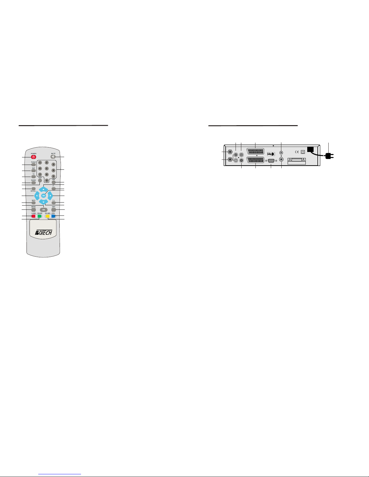
Remote Control Unit
2.2 Remote Control Unit
All features of the set-top box can be controlled with the remote controller.
1. POWER
Turns the receiver On/Off.
2. MUTE
Mutes audio output of the receiver.
4. NUMERIC KEY(0-9)
Controls the numerical operation and especially
changes program directly.
5. SAT
Shows satellites list of the searched channels,
change current satellite.
6. TV
Shows the current digital TV program list.
7. RADIO
Shows the current digital Radio program list.
8. FAV
Shows the current favorite program list.
9. TEXT
Shows the list of subtitle and teletext languages
the current channel supports.
10. RECALL
Shows previous channel.
11. UP/DOWN
Change the current program to the previous/next
program in NO-menu state. Moves the cursor to
upward/downward in Menu state.
3. TV/SAT
Control scart output whenever TV/SAT button
is pressed scart output is changed between
receiver output and VCR input.
12. P+/P Page up and down in menu list.
13. OK
Activates the highlighted menu item.
Display channel list according to TV/Radio Mode.
14. LEFT/RIGHT
Change the setting value in specific Menu item.
15. INFO
Used for special function. Normally used for viewing channel information.
16. MENU
Shows the menu or sub-menu and cancels the processing function if applicable.
17. EXIT
Exits from the menu or sub-menu and cancels the progressing function if applicable.
18. LANG
Shows the list of the audio language available in the current channel.
19. PAUSE
Pause the video/audio output.
20. EPG
View the program guide in No-menu state.
21. SOUND
Select sound mode to stereo or mono.
16
1
3
7
8
11
14
13
12
15
17
18
21
20
4
5
6
19
9
10
2
11
12
14
13
1
7
8
9
11
5
2
2.3 Rear Panel
1. LNB IN
Connect the digital signal from your LNB of your satellite dish to this connector.
2. LOOP OUT
Gives you the possibility to connect an extra receiver(analogue or digital).
3. AUDIO Right(Red RCA) and Left(White RCA)
These connectors give you the possibility to connect the audio signal to an external
amplifier, or the audio input of your TV.
4. VIDEO(Yellow RCA)
This connector has a constant video signal for additional VCR-connections.
5. DC 0/12V 150mA OUT(Black RCA)
This connector gives you the possibility to get a switched 0/12V, 150mA current
from your receiver for an external positioner.
This RCA can be activated per satellite via the On Screen Display(satellite set-up).
Be carefull in connecting and activating this Black RCA. The 0/12V current can
cause severe damage to your equipment if connected in the wrong way.
6. TV Scart Connector
Use this connector to connect your receiver to your TV using a scart cable.
7. VCR Scart Connector
Use this connector to connect your receiver to your video recorder using a scart cable.
Your video signal will now be looped through to you TV.
8. RS232 Serial Port
This serial port can be used to connect your PC to your receiver, and enables you
to download new versions of software into your receiver.
9. ANT
RF Modulator(female part). If you have an additional antenna(cable or terrestrial)
as well, and you do not use a scart cable to connect the receiver to the TV, then your
additional antenna has to be connected here. If you do use a scart cable to connect
the receiver to your TV, the additional antenna can be put directly into your TV.
10. TV/VCR
RF Modulator(male part). If you do not use a scart cable to connect your receiver
to your TV, you will have to use this connector to connect the receiver to your TV,
using a coax cable. If you connect your receiver to your TV like this, be sure that
you set your TV to the Video channel.
11. Power Cord
Your receiver requires a current of 90~240V AC(Auto-selectable), 50~60Hz+/-5%.
Make sure to check the power specification before connecting your receiver to the
wall outlet.
Figure 3. Rear Panel
Rear Panel
CAUTION
RISK OF ELECTRIC SHOCK
DO NOT OPEN
SHOCK HAZARD : DO NOT OPEN
RISQUE DE CHOC : NE PAS ENLEVER
3
4
6
10
LOOP OUT
AUDIO R
VIDEO
AUDIO L
S/PDIF OUT
TV
VCR
ANT
TV/VCR
RS232
AC 90-240V ~
50/ 60Hz
Max. 30W
Designed by L.A in U.S.A
6
7
Page 6
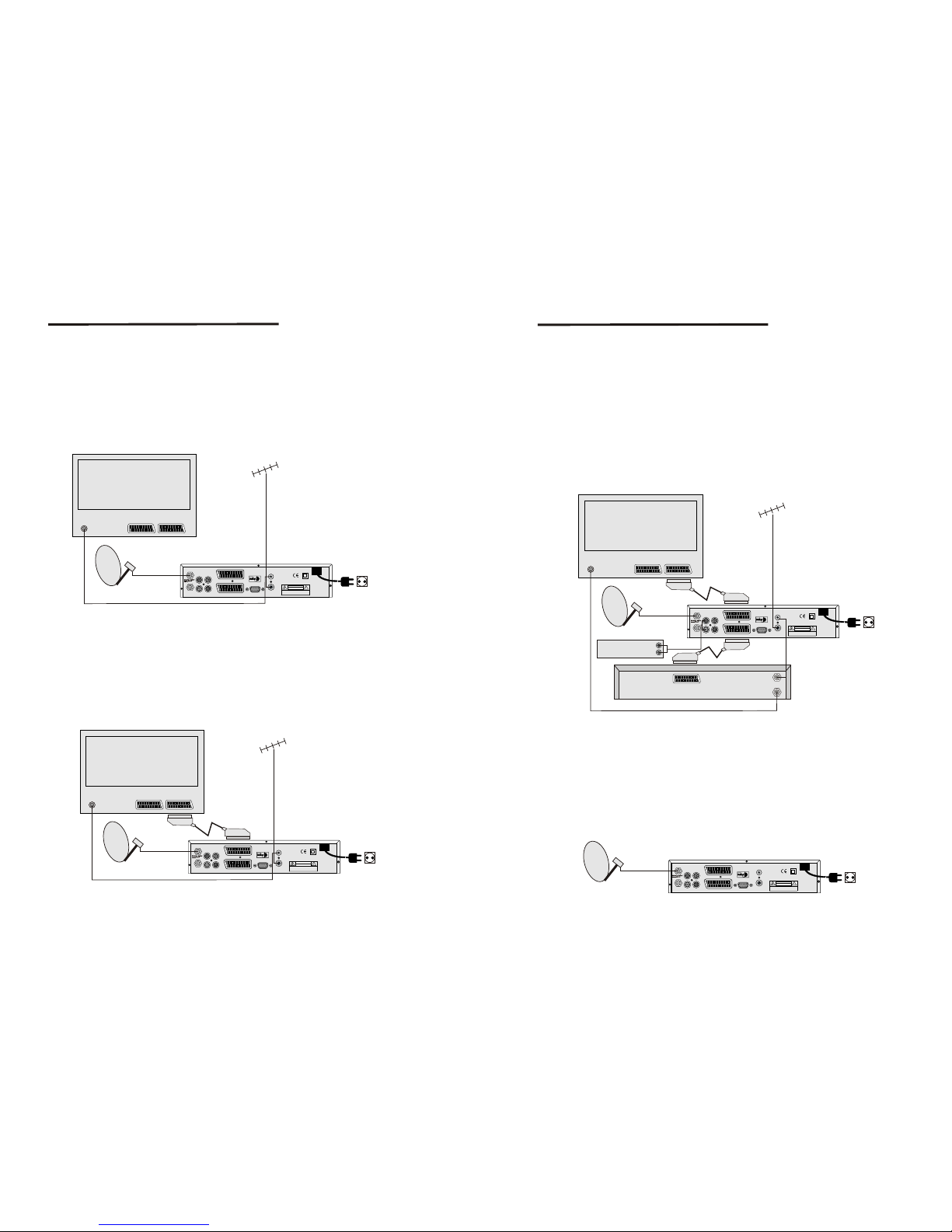
3.1 Connecting to TV & VCR
<Basic connection with a coax cable>
1. Connect the satellite signal from the LNB to the LNB IN connector.
2. Connect the TV/VCR connector at the back of the receiver to the coax IN connector
on your TV set.
3. Optional : connect an extra terrestrial or cable antenna to the ANT connector at the
back of the receiver.
Figure 4 Basic connection with a coax cable
IN
2
1
LOOP OUT
AUDIO R
VIDEO
AUDIO L
S/PDIF OUT
TV
VCR
ANT
TV/VCR
RS232
AC 90-240V ~
50/ 60Hz
Max. 30W
CAUTION
RISK OF ELECTRIC SHOCK
DO NOT OPEN
SHOCK HAZARD : DO NOT OPEN
RISQUE DE CHOC : NE PAS ENLEVER
Designed by L.A in U.S.A
Television
SATELLITE DISH
Terrestrial
Antenna
or
Cable TV
Connection to TV&VCR
LOOP OUT
AUDIO R
VIDEO
AUDIO L
S/PDIF OUT
TV
VCR
ANT
TV/VCR
RS232
AC 90-240V ~
50/ 60Hz
Max. 30W
CAUTION
RISK OF ELECTRIC SHOCK
DO NOT OPEN
SHOCK HAZARD : DO NOT OPEN
RISQUE DE CHOC : NE PAS ENLEVER
Designed by L.A in U.S.A
Terrestrial
Antenna
or
Cable TV
IN
2
1
Television
SATELLITE DISH
< Basic connection with a Scart cable >
1. Connect the satellite signal from the LNB to the LNB IN connector.
2. Connect the TV scart connector at the back of the receiver to the scart-in connector
on your TV set.
3. Optional: connect an extra terrestrial or cable antenna to the ANT connect at the
back of the receiver.
Figure 5. Basic connection with a Scart cable
LOOP OUT
AUDIO R
VIDEO
AUDIO L
S/PDIF OUT
TV
VCR
ANT
TV/VCR
RS232
AC 90-240V ~
50/ 60Hz
Max. 30W
CAUTION
RISK OF ELECTRIC SHOCK
DO NOT OPEN
SHOCK HAZARD : DO NOT OPEN
RISQUE DE CHOC : NE PAS ENLEVER
Designed by L.A in U.S.A
Terrestrial
Antenna
or
Cable TV
<Advanced connection of the receiver to the TV set, VCR and Audio amplifier>
IN
2
1
Television
AUDIO R
AUDIO L
Videorecorder
Audio Amplifer
SATELLITE DISH
IN
OUT
Connection to TV&VCR
Figure 6. Advanced connection of the receiver to the TV set, VCR and Audio amplifier
8
9
3.2 Connecting to Dish
Aiming a satellite dish and LNB to the correct longitude and Azimut (angle of
elevation) of a satellite is a specialist job, and can best be done by an official
botech dealer.
Make your choice of which satellite you want to receive your signals from, and have
your botech dealer aim your dish at the requested satellite. Connect a coax cable to
your LNB and the other end directly to the LNB IN connector of your receiver.
<Connecting a fixed satellite dish to your receiver>
LOOP OUT
AUDIO R
VIDEO
AUDIO L
S/PDIF OUT
TV
VCR
ANT
TV/VCR
RS232
AC 90-240V ~
50/ 60Hz
Max. 30W
CAUTION
RISK OF ELECTRIC SHOCK
DO NOT OPEN
SHOCK HAZARD : DO NOT OPEN
RISQUE DE CHOC : NE PAS ENLEVER
Designed by L.A in U.S.A
Fixed Satellite Dish
(f.i. pointed at Astra)
Figure 7. Connecting a fixed satellite dish to your receiver
1. Connect the satellite signal from the LNB to the LNB IN connector.
2. Connect the TV scart connector at the back of the receiver to the scart-in connector
on your TV set.
3. Connect the VCR scart connector at the back of the receiver to the scart-in connect
on your VCR set.
4. Connect an extra terrestrial or cable antenna to the ANT connector at the back of the
receiver.
5. Connect a coax cable to the TV/VCR connector at the back of the receiver.
Connect the other end of this coax cable to the coax-in connector of your VCR.
6. Connect the coax-out connector of your VCR to the video-in connector of your TV set
with a coax cable.
7. Optional: Connect the audio left and right RCA-plugs(Red and White) on the back of
your receiver to the left and right input of an Audio amplifier, so you can
enjoy the digital quality of the sound that is produced by your botech receiver.
Page 7
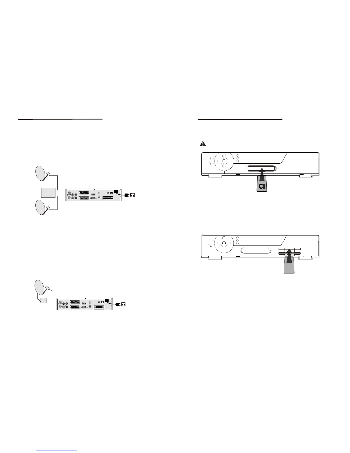
Connection to Dish
LOOP OUT
AUDIO R
VIDEO
AUDIO L
S/PDIF OUT
TV
VCR
ANT
TV/VCR
RS232
AC 90-240V ~
50/ 60Hz
Max. 30W
CAUTION
RISK OF ELECTRIC SHOCK
DO NOT OPEN
SHOCK HAZARD : DO NOT OPEN
RISQUE DE CHOC : NE PAS ENLEVER
Designed by L.A in U.S.A
<Connecting multiple fixed dishes to your receiver using a DiSEqC 1.0
switch>
If you want to watch programms from more than satellites(For in instance from Astra
and from Hot Bird) it is advisable to use fixed dishes and a DiSEqC 1.0 switch. Have
your botech Dealer aim the dishes at the requested satellites and connect the LNB's
with coax cables to the IN connectors of the DiSEqC 1.0 switch. Connect the OUT
connector of the DiSEqC 1.0 switch to the LNB IN connector at the back of your receiver.
Fixed Satellite Dish 1
(f.i. pointed at Astra)
Fixed Satellite Dish 2
(f.i. pointed at Astra)
DiSEqC
Switch
IN
IN
OUT
Figure 8. Connecting multiple fixed dishes to your receiver using a
DiSEqC 1.0 switch
LOOP OUT
AUDIO R
VIDEO
AUDIO L
S/PDIF OUT
TV
VCR
ANT
TV/VCR
RS232
AC 90-240V ~
50/ 60Hz
Max. 30W
CAUTION
RISK OF ELECTRIC SHOCK
DO NOT OPEN
SHOCK HAZARD : DO NOT OPEN
RISQUE DE CHOC : NE PAS ENLEVER
Designed by L.A in U.S.A
<Connecting a dish on a motorized positioner to your receiver>
Satellite dish on
moterized Positioner
IN
OUT
Figure 9. Connecting a dish on a motorized positioner to your receiver
10
11
VOL+
VOL-
STAND BY
LOCK
MESSAGE
Figure 11. Connecting to SMART CARD
3.4 Connecting to SMART CARD (CAS Model Only)
Insert Smart Card into Smart Card slot for watching TV programmes from Service
Provider.
S
STAND BY
LOOK
MESSAGE
VOL +
VOL -
Figure 10. Connecting to CI Module
3.3 Connecting to CI Module(CI Model Only)
Connection to CI Module
Insert CI module into CI slot for watching TV programmes from Service Provider.
Do no plug in/out CI module when the receiver is powered on.
But you can insert smart card to CI module with power on.
Warning
An other posibility to watch programms from multiple satellites is by mounting a dish to
a motorized DiSEqC 1.2 positioner. Have your botech dealer mount the dish to the
positioner, set the correct azimut (angle of elevation) and let him set the center point
for your positioner. Connect the LNB with a coax cable to the LNB IN connector of
the positioner, and connect the OUT connector of the positioner to the LNB IN
connector at the back of your receiver.
Page 8
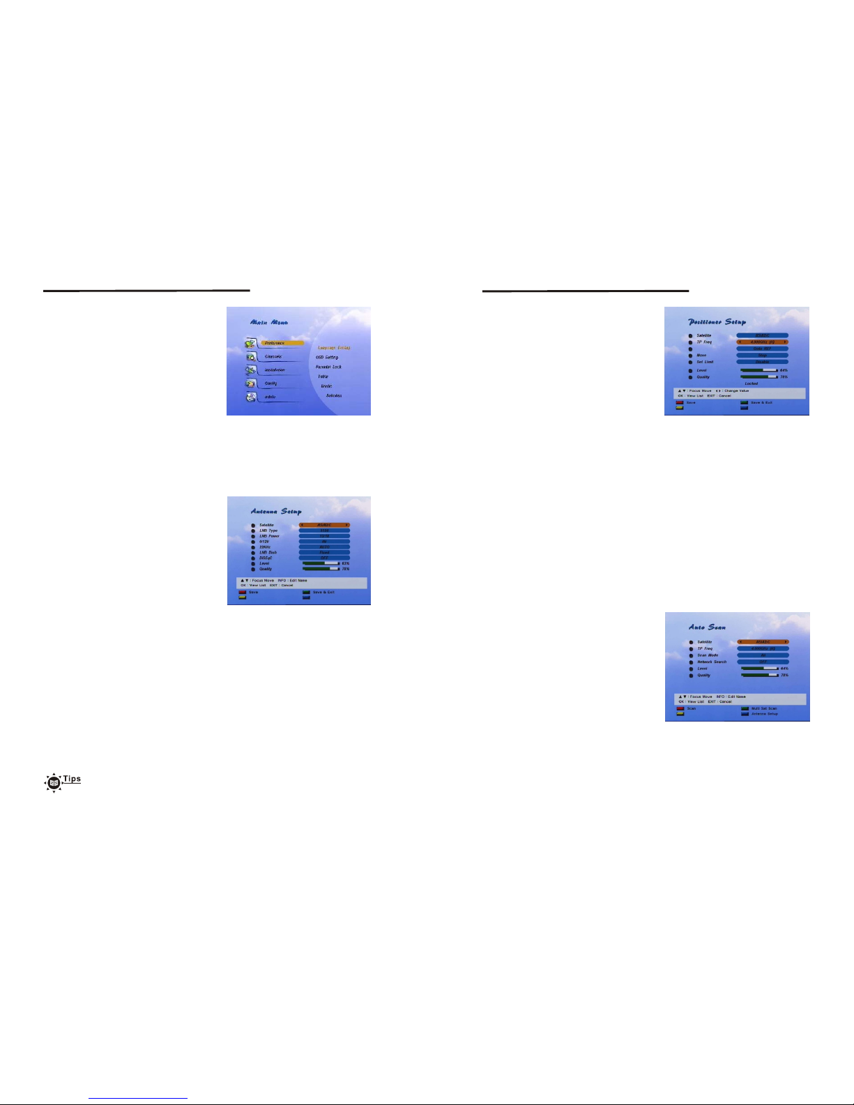
Setting and Operations
<Starting up for the First Time>
<Menu Information>
4.1 Before Settings
1. Turn on your TV and receiver.
2. If it is first time using a receiver, you should
set parameters for system configuration.
After displaying the login screen, press
the MENU button.
The <screen1> will be appeared.
The menu consists of main-menu and sub-menu, as you see in the <Screen 1>.
Main-menu has 4items(5 items for CI Model) and each main-item has its sub-menu
items.
<screen 1>
<Antenna Setup>
4.2 Basic Settings
With this menu, you can designate the
satellite to search channels.
There are up to 64 satellites available.
In this menu, you can edit the satellite name.
1. If you press OK in Antenna Setup of
Installation Menu, the <screen 2> will be
appeared.
2. Use the Up/Down button to select the item,
and set up the parameter with the Left/Right
button.
3.If you completed setting, use Red button
to Save, Green button to Save/Exit.
<screen 2>
Satellite : If you press OK in Stellite, the satellites list is displayed. Move the cursor
to a satellite and press OK to select the satellite and have the list disappeared,
or press EXIT on the remote controller to cancel the setting and have the list
disappeared. If you want to rename the satellite, press the INFO button on
the remote controller at the satellites list.(see 4.9 Name Edit)
LNB Type : You can select one the LNB type from Universal(9750~10600), 5150, 9750,
10000, 10050, 10600, 10750, 11200, 11475, or user defined type.
You should input LNB value directly in user defined (default value is 0).
LNB Power : You can select 13V or 18V for LNB. Select Off if you want to off LNB power.
0/12V : Setup the 0/12V switch option.
22KHz : Setup the 22KHz switch.
If you have connected to a dual LNB or two antennas connected to a 22KHz tone
switch box, set it to "ON".
LNB Dish : Use this option to use the Digital Positioner. The default is Fixed.
If you want to move the dish, set the LNB Dish field to Moved.
DiSEqC switch : The default is Off. To use the DiSEqC switch, set up DiSEqC.
If you had set LNB Type to Universal, LNB Power and 22KHz switch
options are disregarded. If you set LNB Dish to Moved, DiSEqC switch
is disappeared and positioner item is appeared. On the other hand, if you
set LNB Dish to Fixed, positioner item is disappeared and DiSEqC switch
is appeared. Universal LNB : 9750 ~ 10600MHz
12
13
Setting and Operations
<Positioner Setup>
If you use DiSEqC digital positioner you can
set dish position from Antenna Setup menu.
First, change "LNB Dish" value to Moved
then DiSEqC menu item is changed to
Positioner item. If you already set dish
position for current satellite item value is
displayed as "Setup(NOT SET)". To set dish
position press OK button. Positioner menu
will be displayed.
<screen 3>
Satellite : You can select other satellite to scan channels using Left/Right or satellite
list(If you press OK button, then satellite list will be displayed).
Tp Freq : Shows a TP value of the current satellite. If you want to see another TP value
press OK for TP list or press Left/Right to change TP.
Scan Mode : You can designate scanned channel type as FTA channel only or All
channels(FTA + Scrambled channel).
Network Search : Set this field to ON to perform Network TP Search.
If you press Red(Scan) button all transponders of current satellite are scanned.
<Auto Scan>
If you already set the Antenna set up you can
scan the satellite. In this menu, you can
edit the satellite name and select Tp Freq,
Scan Mode, Network search.
1. If you press OK in Auto Scan of Installation
Menu, the <screen 4> will be appeared.
2. Use the Up/Down button to select the item,
and set up the parameter with the Left/Right
button.
3. If you completed setting, use Red button
to Scan, Blue button to go to Antenna Set-up
menu.
<screen 4>
If dish position is moved to correct position to receive satellite signal, signal level
and quality color are changed(for example to Green), To save current dish position
use Red(Save) or Green(Save & Exit) button.
Satellite : Show the satellite name dish position is seted. If you want to change satellite
you should change satellite from Antenna Menu.
Tp Freq : Show TP of the designated satellite.
Signal level and quality is checked on the base of current TP value.
If you want to change to other TP use Left/Right button or OK button, then
TP list will be displayed.
Goto REF : You can use this item to move dish position to center.
If you press OK button dish position is moved to center position.
While position is moving to center, wait message is displayed.
Move : Use to move dish position to east or west direction.
Whenever Left button is pressed dish position is moved to east direction.
And moved to west direction when Right button is pressed.
Set Limit : Set dish position's east or west limit, disable limit value.
Change item with Left/Right button and press OK button to set/disable
limit value.
Page 9
Setting and Operations
Setting and Operations
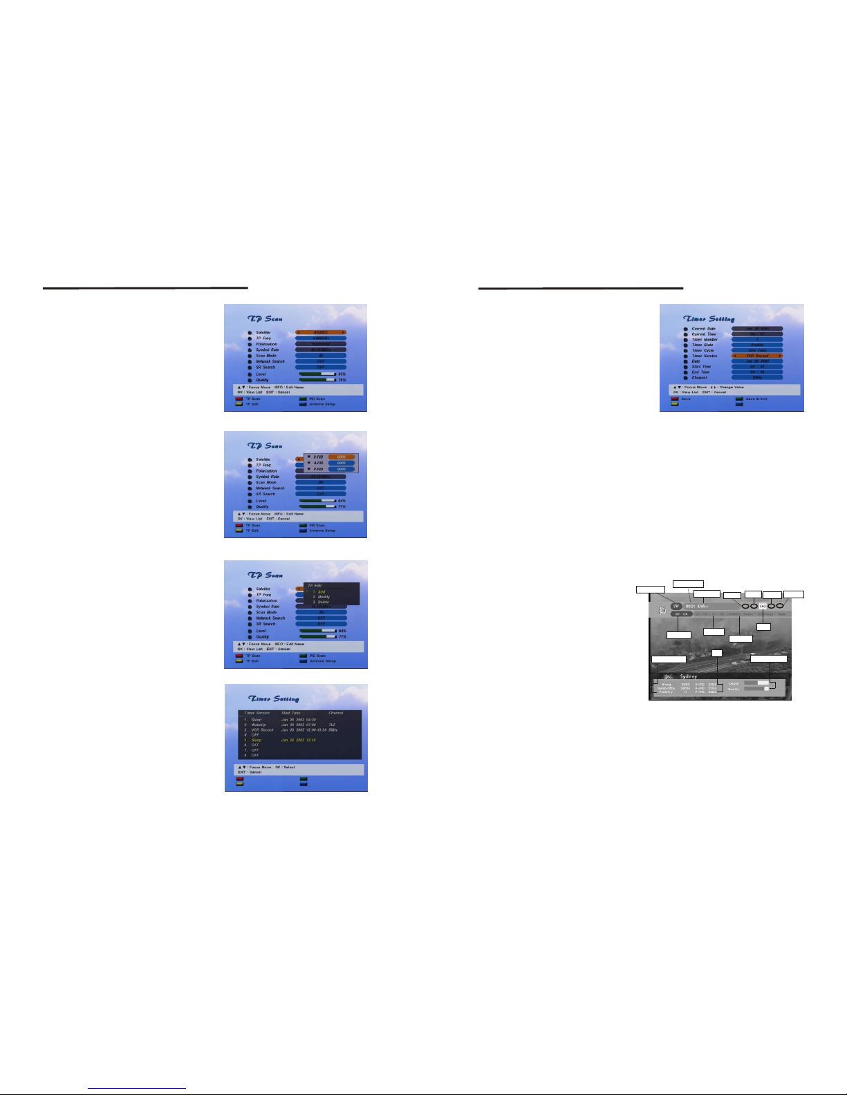
<Manual Scan>
1. If you press OK in Manual Scan of
Installation Menu, the <screen 5> will be
appeared.
2. Use the Up/Down button to select the item,
and set up the parameter with the Left/Right
button.
3. If you completed setting use Red(TP Scan)
button to scan current transponder channel,
Green button to enter PID scan mode,
Yellow button to edit TP information, Blue
button to go to Antenna Setup menu.
TP Scan : Searches channels from a specific
transponder.
PID Scan : You can search a specific channel
by entering the PID value of a
channel.
<screen 5>
If you press Green(PID) button, the PID
screen is displayed as below.
Enter the PID value and press the PID button
again.(To cancel the PID value, press Exit on
the remote controller, or press the Blue(PID)
button to search the channel. You should
enter V-PID, A-PID, and P-PID)
<screen 6>
<Timer Setting>
You can set the time to make the receiver
perform the designated actions including
timer based recording(VCR), wake up/sleep
the set-top-box.
You can see the current setting state of all
timers.
1. If you press OK in Timer Setting of Installation
Menu, the <screen 8> will be appeared.
TP Edit : If you press Yellow button You can
edit the TP value. Press OK in the
Add item to add the new TP value,
in the Modify item to change the
current value, in the Delete item to
delete the current TP value.
<screen 8>
<screen 7>
14
15
<screen 9>
Use the Up/Down button to select the item,
and change the parameters using Left/Right
button. If you completed timer settings, use
Red(Save) or Green(Save&Exit) button to
save timer setting.
Timer Number : You can select up to 8 timers.
Timer State : You can make this state Enabled to use the timer function.
Timer Cycle : You can set the cycle of the action designated in the timer mode.
Timer Service : You can set the service(Sleep, Wake up, VCR Record) of the action
designated in the timer mode.
Date : You can set the starting date of the timer action.
If you press OK, calendar is displayed.
Start Time(sleep time/wakeup time) : You can set the starting time of the timer action.
Ending Time : You can set the ending time of the recording when the Timer mode is
VCR Record.
Channel : You can select the program channel recorded when Timer mode is VCR
Record. When Timer service is wake up, this channel is viewed receiver
is powered on by timer function.
4.3 TV menu at the normal mode(No menu state)
At normal mode, various menus are
displayed on the screen with remote
control action. You can change the
current status and mode with various
buttons including the Up/Down, SAT,
INFO and EPG button. <Screen 10>
shows the banner displayed when
you press the INFO button. If you
the button again before the
banner on the upper part of the screen
is disappeared, another banner is
displayed on the bottom of the screen.
The bottom banner shows information
on the current channel.
press
<screen 10>
TV/Radio mode
Channel number
Current time
Cannel information
PID
Signal level/Quality
Event time
Event name
Sound
Channel name
Subtitle
Teletext
Scramble
AC3 Audio
50%
80%
- MUTE : Mutes the current channel audio.
- POWER : Turns the receiver power on/off.
- SOUND : Sets the current channel audio to stereo/left-mono/right-mono.
- TV/RADIO : Changes the current mode. If you press the Radio button at TV mode,
the system changes into the Radio mode, and if you press the TV button
at Radio mode, the system changes into the TV mode. And if you press
the TV button at the TV mode, or the Radio button at the Radio mode,
the TV/Radio list menus are displayed. (The menus are the same as
those of Channel Manager, but are not available to edit. To edit, use the
Channel Manager of the Main menu.)
2. Use the Up/Down button to select the
timer, and press OK button to setup
selected timer information. Following
screen will be displayed.
Page 10
- SAT : The current TV/Radio list is for the channels searched in a satellite. If you
change the satellite with the SAT button, the list is updated with the channels
searched in the satellite. (The channel list is configured with the channels
searched in a satellite. If you set up the digital positioner to change the satellite,
a message wait moving dish is displayed. The SAT button is disabled in the
favorite channel mode because there can be a number of different satellites.)
- Numeric Key(0-9) : You can change channel by inputting channel number directly.
- Up/Down : Moves to the previous/next channel.
- Left/Right : Adjusts volume.
- LANG : Shows the list of the audio language available in the current channel. (The
selected audio language information is saved and applied when you watch
the channel.)
- FAV : The Favorite List is displayed.
- MENU : You can enter the Main Menu.
- OK : You can select an item in the SAT, SUBTITLE or LANG list.
Program list is displayed according to TV/Radio Mode.
- EXIT : The button makes a banner or other lists including SAT, SUBTITLE and LANG
disappeared.
- EPG : The EPG menu of the current TP is displayed.
- SUBTITLE : Shows the list of subtitle languages the current channel supports.
- PAUSE : Pause the video/audio output of receiver.
To clear pause press PAUSE button again.
- INFO : If you press the INFO button once, a banner is displayed on the upper part of
the screen, and if you press the button again before the upper banner is
disappeared, a new banner is displayed showing the details of the currents
channel.
Tips
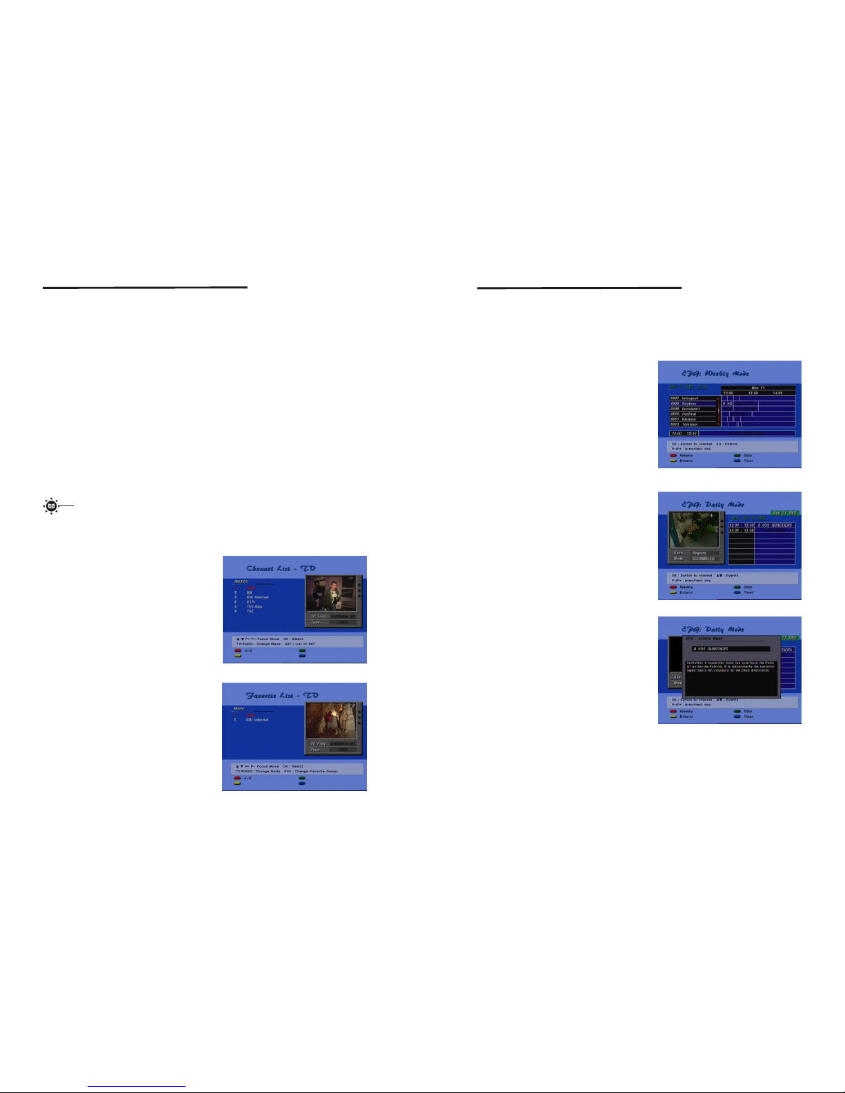
TV/Radio/Favorite List is classified into the Simple mode and the Edit mode.
If you press TV/Radio/Fav at Normal, the Simple mode menu is displayed.
The simple mode provides fast channel move and fast display of basic
information, but does not provide the Edit function. If you want to edit, select
Channels Manager and Favorites Manager of Main Menu at Normal status.
The TV/Radio/Favorite menu displayed in this section is the Simple mode.
To use edit function, see 4.5 Channel Manager and 4.7 Favorites Manager.
<TV/Radio List in Simple mode>
<Favorite List in Simple mode>
If you press TV/RADIO/OK on the remote
controller, at No menu state, the screen is
displayed as follows.
You can preview the channel and move the
channel fast with the P+/P- button.
If you press FAV on the remote controller
at No menu state, the screen is displayed
as follows.
You can preview the channel and move the
channel fast with the P+/P- button.
<screen 11>
<screen 12>
16
17
4.4 EPG
EPG shows the event information on the current TP channel by time Zone. EPG is
divided into Weekly mode, Daily mode, and Extend mode, an d provides tim er based
recording and automatic power ON/OFF. The event is displayed only at the channel
that have EPG information. If you press EPG, the Weekly mode is displayed as a default.
Weekly
The current TP channel list is displayed on
the left, and the event information is displayed
on the right by time zone. To view the detailed
information of an event in the Extend mode,
press Yellow(Extend) with the Left/Right/Up
/Down key. If you want to display the Daily
mode of the current channel, press Green
(Daily). Press EXIT to close the EPG menu.
<screen 13>
Daily
Extend
Shows the designated channel in PIG, and
displays the channel even t in det ail.
If you press Yellow(Extend), an Extend
window is displayed as in the Weekly mode,
showing detailed information of the event.
Press EXIT to close the EPG menu.
Shows the detailed information of the cu rrent
event . To close the mode, press EXIT on the
remote controller.
<screen 14>
<screen 15>
Setting and Operations
Setting and Operations
Page 11
<screen 16>
Timer
Move the cursor to an event in the required
time zone, and press Blue(Timer).
Then the timer is set to the designated time.
See the Timer Settings for details
You can change channel information in the
"Channel Manager" of Main Menu.
Use TV/Radio button to view TV/Radio
channel list. Use SAT button to view other
satellite's channel list.
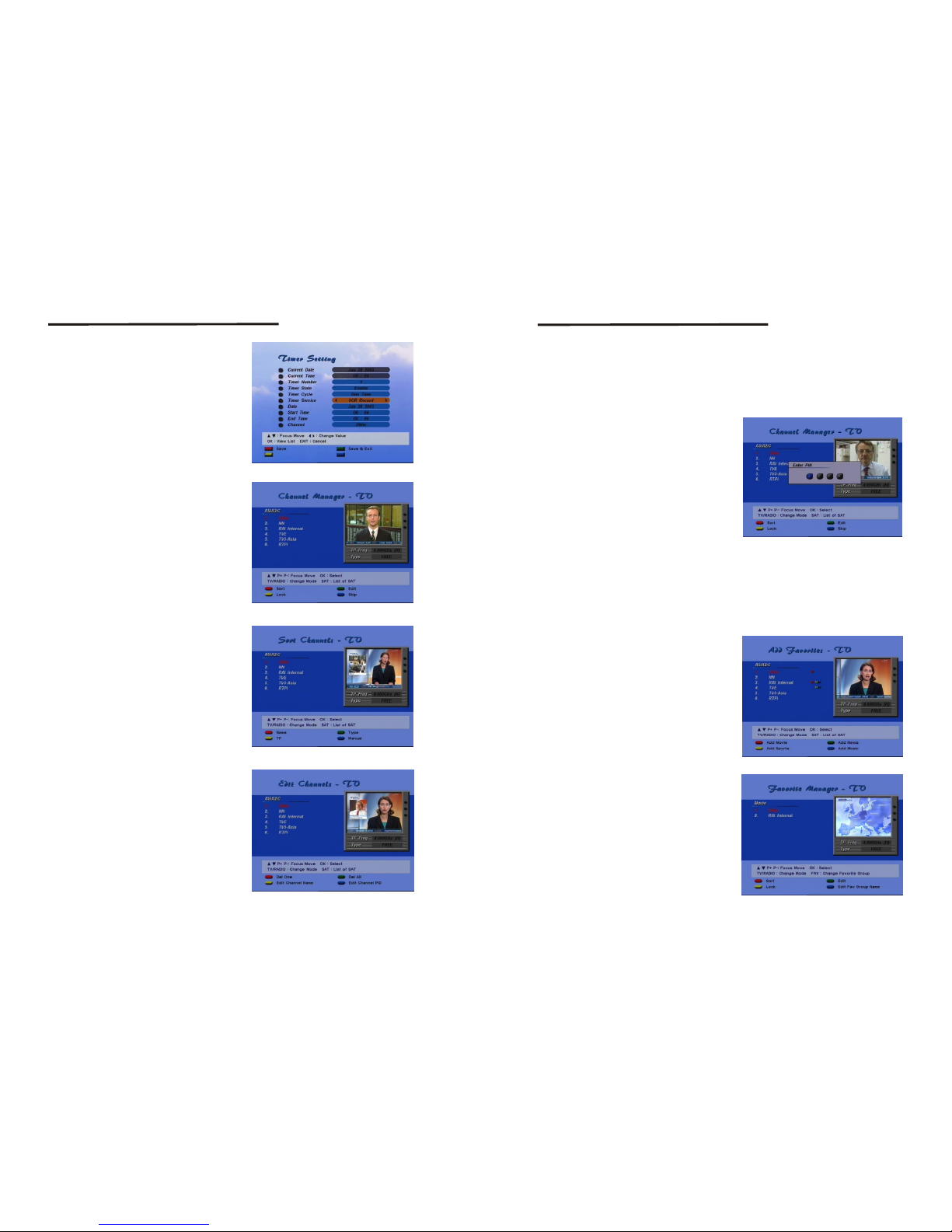
4.5 Channel Manager(Edit Mode)
<screen 17>
Sort
You can sort channel orders of channel list.
Use the 'Sort' button.
Name : Sort channel order by channel name.
Use the 'Name' button.
Type : Sort channel order by channel status.
Free and Scrambled.
Tp : Sort channel orders by transponder order.
Manual : You can move a channel position.
<screen 18>
Then check mark will be shown on the
selected channel. Use the cursor move
buttons to move to the position that you
want. Use the 'Manual' button again.
Be aware that the function can completely
delete the saved channels. When you delete
a channel in Channel Manager, the channel
is also deleted from the Favorite List.
EDIT
You can change a channel name or PID and
delete one or all channels on the current
satellite channel list.
<screen 19>
First use the 'Manual' button.
Delete One : You can delete current
selec ted channel only.
Use 'Del One' button.
Delete All : You can delete current list's all
channel. Use 'Del All' button.
18
19
Setting and Operations
Setting and Operations
Edit Channel Name : You can edit current channel name.
Press 'Edit Channel Name' button(Yellow).
Edit window will be displayed.
Edit Channel PID : You can edit channel PID in formation. Use 'Edit Channel PID'
button(Blue). Channel PID edit menu will be displayed. (The
changed PID value can be disregarded if the PID information is
updated from satellite.)
LOCK
SKIP
<screen 20>
If channel lock status is enabled, you must
enter PIN code to view channel.
If channel skip status is enabled, channel cannot be viewed on a channel view operation.
4.6 Add Favorites
You can designate the channels of the current TV/Radio list as the favorite channels.
The default favorite list names are "Fav1", "Fav2", "Fav3", "Fav4". Move to the required
channel with Up/Down or P+/P- button, and then press color button on the remote
controller to set channel as favorites. For
example, if you press Red(Fav1) button the
channel is designated as 'Fav1' favorite
channel. If Red button is pressed again the
selected channel is un-selected from "Fav1"
favorite list. One channel can be selected
into more than one favorite list.
You can change default favorite list name
from Favorite Manager menu. To select
Radio channel in the TV list use Radio button,
and use TV button in the Radio channel list.
You can see the favorite list if you press the
'Fav' button while you are watching TV(or
listening Radio channel) in Normal State.
<screen 21>
4.7 Favorite Manager
<screen 22>
The function is basically the same as the
channel manager menu in 4.5.
- Sort :Same as the Sort function of channel
manager menu in 4.5.
- Edit :Same as the Edit function of channel
manager menu in4.5.
- Lock :Same as the Lock function of channel
manager menu in 4.5.
- Fav Group Name : You can edit the name
of the favorite group.
(See 4.9Name Edit)
Page 12
4.8 Other Settings
The Preference menu has following 6 sub-menu.
- Language Setting
- OSD Setting
- Parental Lock
- Tetris
- Snake
- Sokoban
And The Config menu has following 5 sub-menu.
- TV Settings
- Time Settings
- Clear Data
- System Information
- System Upgrade
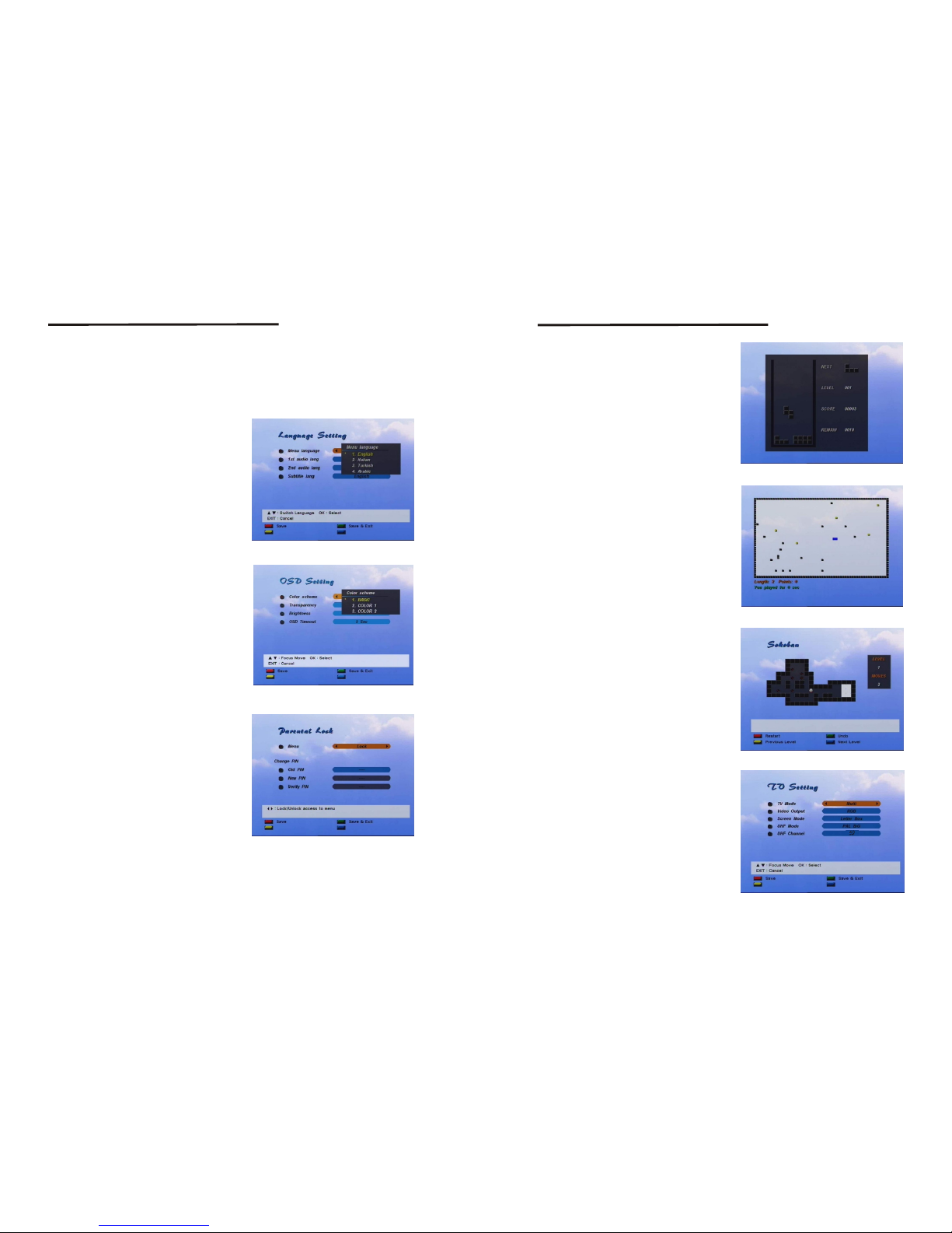
<Language Setting>
You can select OSD menu language, Audio
language and subtitle language. Use the
Right or OK button to view language list.
<screen 23>
<OSD Setting>
<Parental Lock>
- Color scheme : You can select other OSD
color pattern.
- Transparency : You can control OSD
transparency level.
- Brightness : You can control OSD
brightness level.
- OSD Time-Out : Select the time how long
the banner will be visible
when banner is displayed.
Changes the Personal Identification Number
(PIN) which is used to control the access to
the receiver and individual channel.
- Menu Lock/UnLock
- Change PIN
If menu is set to Unlock, the receiver doesn't
ask to input your PIN in the menu operation.
Use the Left/Right button to change menu
lock status. If the lock key message is
inconvenient, set the key to UnLock.
To change the current PIN, First you can
input the current PIN and then input new
PIN you want to use and then confirm this
new PIN. After changing, you must save the
PIN configuration using the Save button.
<screen 24>
<screen 25>
20
21
Setting and Operations
Setting and Operations
<Tetris>
If you want to play game, Select the
Preference item and use the tertris button.
- Left/Right button : Move block to a left or
right direction
- Down button : Drop block
- OK : Rotate block
If you want to stop the game, use the EXIT
button.
<screen 26>
<Snake>
- Left/Right button : Move snake icon to
left or right direction.
- Up/Down button : Move snake icon to up
or down direction.
If Blue snake icon is passed through the
green icon length is increased, but passed
through the yellow icon length is decreased.
If passed through Gray icon current game
mode is ended.
<screen 27>
<Sokoban>
You are the sokoban and you have to push
the balls to their correct positions(SKYBLUE
square). The balls can only be pushed,
never pulled, so you have to be careful not
to push them into a corner where you can't
get them out again. You can only push one
ball at the time.
<screen 28>
You can move around by using the arrow
keys. You can restart level by using color
key(RED). You can use undo function by
using color key(GREEN) for moving cancel
(Only one step). You can go to previous or
next level (between completed level) by
using color key(BLUE, YELLOW)
<TV Settings>
- TV Mode
You can select OSD & video display mode
to one of Multi, PAL, NTSC. When PAL
mode is selected, for example All screen
is displayed as the PAL mode in spite of
the current Programs transmission mode.
- Video output
You can change the SCART output signal
into Composite (CVBS) or RGB color
composition.
<screen 29>
Page 13
- Screen Mode
When program transmission is in 16:9 and you have a TV set with the 4:3 picture
format you can select Full screen or Letter Box picture format.
- UHF Mode
If TV is connected by RF cable, you can select the RF modulator type RF modulator
type affects a programs audio.
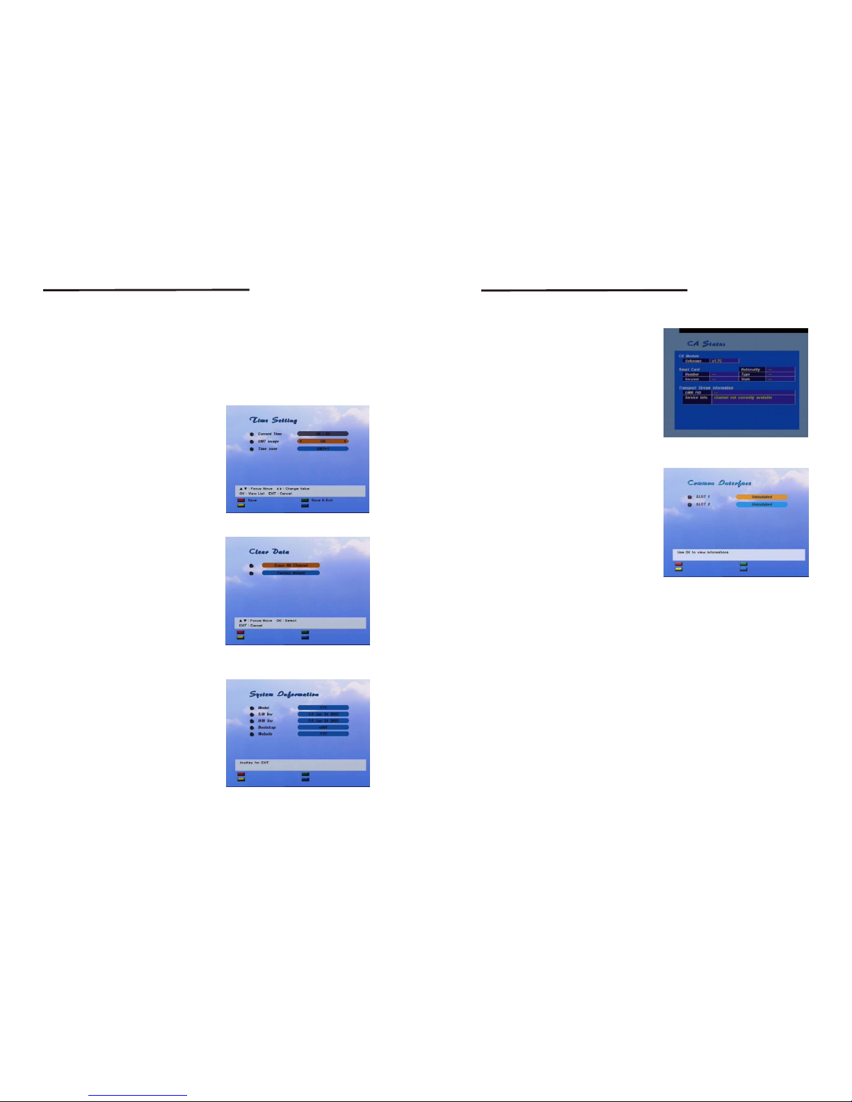
<Time Setting>
If a broadcaster porvides GMT, you can set
the time using GMT, or set your own time by
yourself. If the GMT usage is on, Current
time is automatic ally set and you can only
set the time zone. If you set GMT Usage to
OFF, "Set Data" and "Set Time" item are
displayed. To set date value press OK button
on the item then calendar window is displayed.
You can select date from calendar. To set
time value move cursor to time item and use
numeric button on the remote controller.
<screen 30>
- UHF Channel
When TV is connected by RF cable, you must select RF channel number to the same
value on the TV. If other number is selected the picture will not be viewed.
<System Information>
Shows the system information including the
Firmware version and model name.
<screen 32>
<Clear Data>
- Factory Default : Deletes all the data
currently saved and set.
and returns the system
to the initial status.
- Erase All Channel : Deletes only the saved
channel datas other
setting values are not
deleted.
<screen 31>
22
Setting and Operations
Setting and Operations
<Irdeto>
- CA Status
CA status displays.
Smart Card EMM/ECM information.
<screen 33>
<Common Interface>(CI Model Only)
You can navigate the menu, which is
provided by CI Module.
This information varies a lot depending on
the service provider.
<screen 34>
Page 14
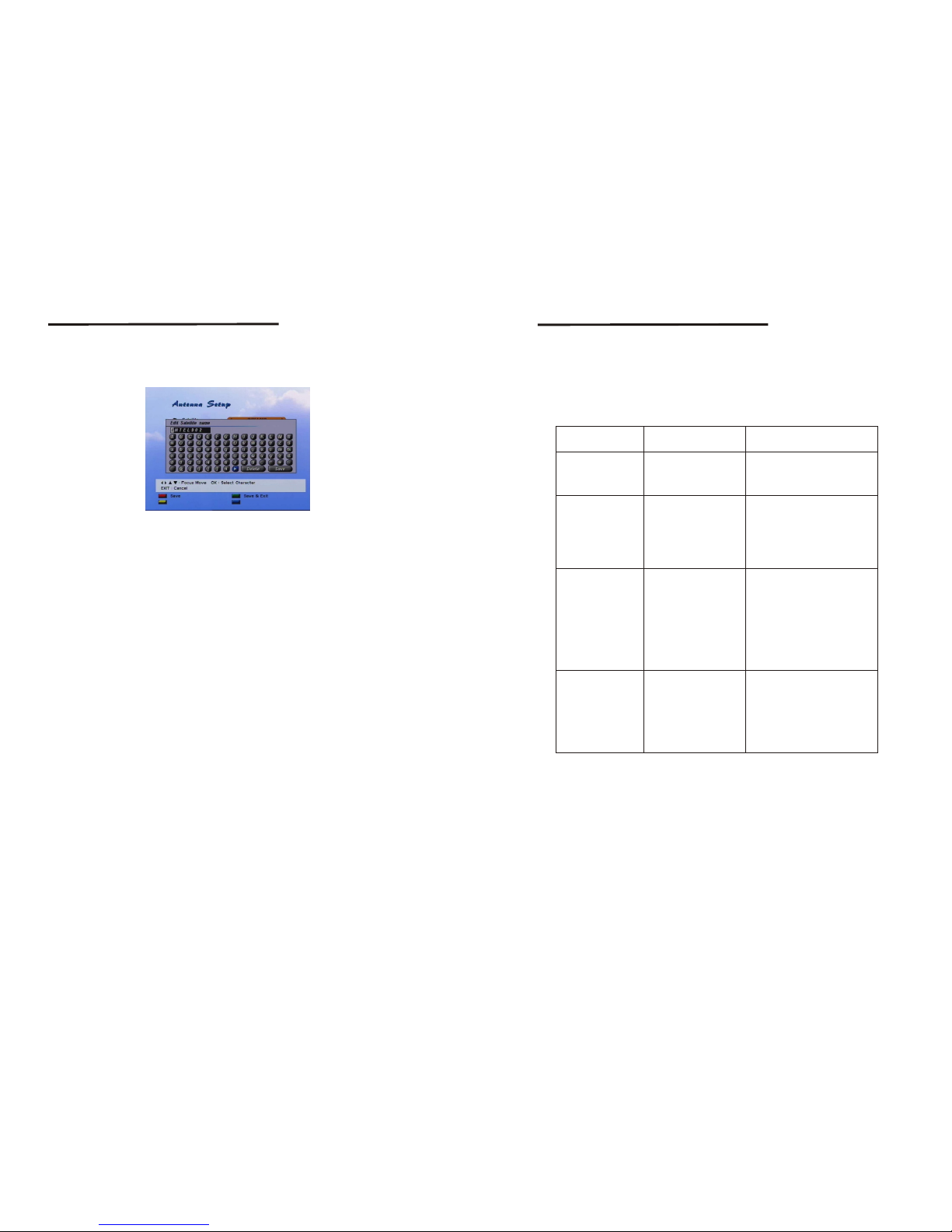
The name editing is the same for each menu. You can change the following names;
Channel name, Favorite Group name and Satellite name.
Use the Left/Right/Up/Down button to move keypad cursor to the character you wish
to input. After you select a character on keypad press OK, then the character in the
name box is replaced(or inputted) with the character.
To move character input position of the name box, select <or> character on the keypad.
If you completed editing move keypad cursor 'Save' key and press OK button.
<screen 35>
4.9 Name Edit
24
25
Setting and Operations
A.1 Trouble Shooting
There may be various reasons for the abnormal operation of the receiver.
Check the receiver according to the procedures shown below.
If the receiver does not work properly after checking it, please contact the dealer.
Don't open the receiver cover. It may cause a dangerous situation.
Symptom
Cause
Remedy
The display on front
panel does not light up.
No picture or sound
No picture
The remote controller
does not working
The batteries of the remote
controller are not inserted
or exhausted
Check whether the batteries are
inserted correctly in your remote
controller
Check the batteries, an if exhausted
replace the batteries of
the remote controller
Wrong connection of the
Audio/Video output of
the receiver to TV.
Audio muting.
TV power off.
Connect the Audio/Video output
of the receiver to TV correctly.
Press the MUTE button.
Turn TV on.
The power cord is not
plugged in.
The receiver can't
receive the signal.
Incorrect values of some
tuner parameters.
Wrong direction of the dish
Check the antenna cable, replace
the cable, or connect the cable to
the receiver tightly.
Set the values of tuner parameters
correctly in installation menu.
Check the signal strength with a
spectrum analyzer and adjust
your dish correctly.
Check that the power cord is
plugged in to the wall outlet.
Trouble Shooting
Page 15
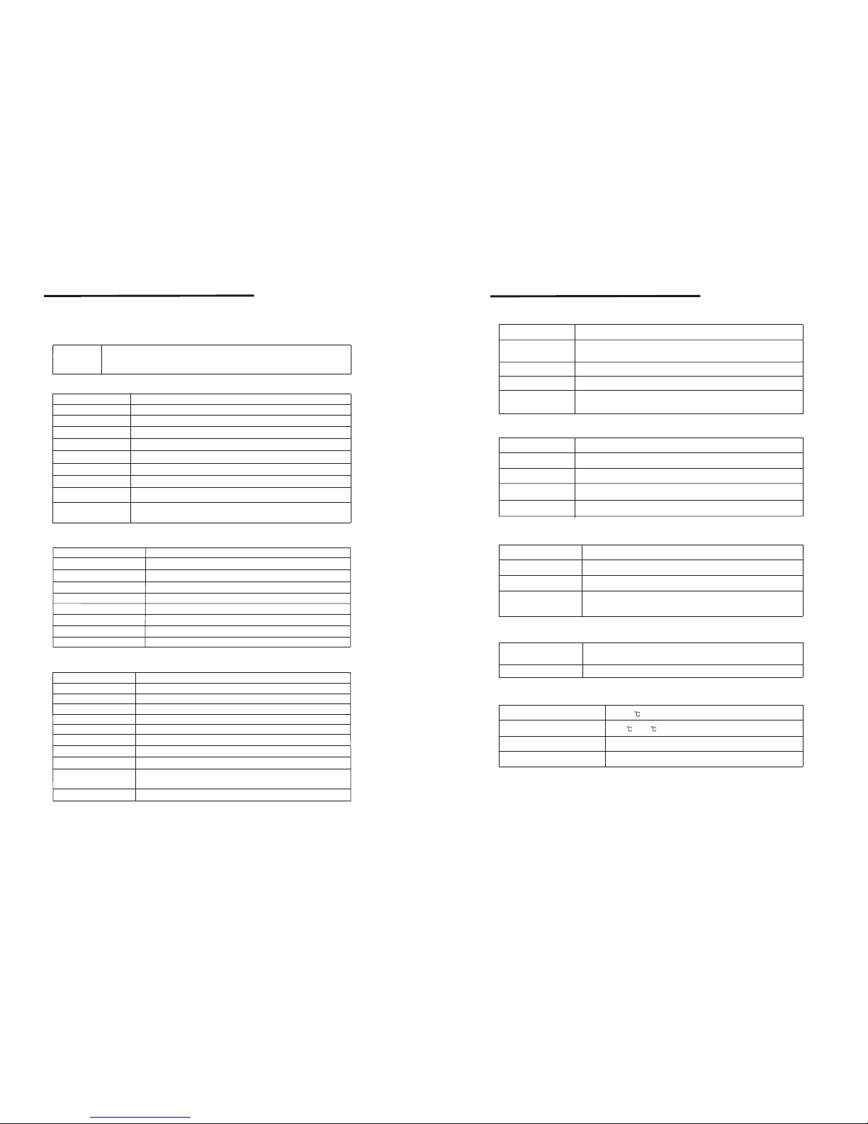
A.2 Specifications
1. Conditional Access Interface(CI Model Only)
2. Tuner & Channel <Digital Part>
PCMCIA
2 Slot(type I or type II)
DVB Common Interface Standard
(Viaccess, Nagra Vision, Conax, Cryptoworks, Irdeto, ASTON)
Type
1X F-type, IEC169-24 Female
950MHz to 2150MHz
-25 to -65 dBm
13/18Vdc 5%, 0.5Amax, Overload protected
75 ohm unbalanced
Version1.2 Compatible
2-45Ms/s
Convolution Code Rate 1/2, 2/3, 3/4, 5/6 and 7/8 with
Constranit Length K=7
QPSK
Frequency:22kHz 2kHz Amplitude:0.6V 0.2V
Frequency Range
Singal Level
LNB Power
Input Impedance
22kHz Tone
DiSEqC Control
Demodulation
Input Symbol Rate
FEC Decoder
+
+
+
_
_
_
Main Processor
Flash Memory
SDRAM
EEPROM
Front
Remote Controller
Multi-Language Menu
Multi-Satellite
Up to 64
7 Keys, 4-Digit 7-Segment Display
34 Keys, IR Remote Control
English/Italian/Turkish/Arabic
Channel Memory
2 Mbytes
8 Mbytes
16Kbytes
Digital Channel : 4900
STi5518
3. System & Memory
Specifications
Transport Stream
Profile Level
Input Rate
Aspect Ratio
Frame Rate
Video Resolution
Teletext
Audio Decoding
Audio Mode
Frequency Response
Single channel/Dual channel Joint Stereo/Stereo
20Hz~20kHz, <+/-2dB
60Hz~18kHz <+/-0.5dB
MPEG/MusiCam Layer I & II, MP3, AC3
Through VBI & OSD
25H for PAL, 30Hz for NTSC
4:3, 16:9
MPEG-2 MP@ML
Max 60Mbit/s
MPEG-2 ISO/IEC 13818 Transport Stream Specification
720 X 576(PAL),
720 X 480(NTSC)
4. MPEG Transport Stream & A/V Decoding <Digital Part>
Sampling Rate
32, 44.1, 48kHz
26
27
TV Scart Output
VCR Scart In/Out
RCA Output
0V/12V Output
Data Interface
RCA Jack Output(Black, Jack), Max 150mA
CVBS, L, R Output(Yellow, White, Red Jack) with Volume Control
CVBS, L, R Output with Volume Control
CVBS, L, R In
CVBS, L, R Out
RS-232, Bit Rate:115200baud
Connector : 9-Pin D-Sub Male type
5. A/V & Data In/Out
6. RF-Modulator
7. Power Supply
RF-Connector
Frequency
Output Channel
Audio Output
Preset Channel
Mono with Volume Control
75W IEC169-2, Male/Female
470MHz to 860MHz
CH 21-69 for the Demodulator
CH 40(or TBD), Software changeable by Menu screen
Input Voltage
Power Consumption
Stand-by Power
Protection
AC 90~240V, 50Hz~60Hz
Max. 30W
<= 6.5W
Separate Internal Fuse
The input shall have the lighting protection
8. Physical Specification
9. Environmental Condition
Operating Temperature
Storage Temperature
Operating Humidity Range
Storage Humidity Range
0~40
-30 ~ 80
10 ~ 85% RH, Non-condensing
5 ~ 90% RH, Non-condensing
Size(WxHxD)
Weight
2.0kg
280 X 55 X 235mm
Excluding the foot. Foot height is 6mm
Specifications
Page 16

A.3 Glossary of Terms
C band
3.7 ~ 4.2 Hz Frequency.
DiSEqC
Digital Satellite Equipment Control.
Ku band
11 ~ 18GHz Frequency.
LNB(Low-Noise Block converter)
The LNB is an electronic unit mounted on the satellite dish.
It receives the signals reflected by the dish ad converts them to signals that can be
used by Satellite receiver.
PID
Package Identifier.
PIN Code
Personal Identification Number.
A four-digit code that is used for locking/unlocking. e.g. with the parental control
feature.
Polarization
Polarization allows several programmes to be fitted into the same frequency band.
The signals from a satellite are transmitted either with linear(vertical or horizontal)
polarization or circular(right or left) polarization.
RS232
Serial data port.
Glossary of Terms
28
 Loading...