


HIGH PROFILE SEAT
CATALOG NO.
1204944-001
REV A
WIDE RIDE II SEAT
(OPTIONAL) DRIVER / PASSENGER SWIVEL, ADJUSTABLE ARMREST, AUTO LEVEL AND HEAT /VENT.
OPERATION AND SERVICE PARTS MANUAL
This seat conforms to
FMVSS 207 and 302 in effect
on the date of manufacture
1

WARNING
SERIOUS INJURY MAY OCCUR IF HEAD CLEARANCE
VEHICLE, ENSURE THAT THERE IS ADEQUATE HEAD
TRAVEL OF SEAT. SEE OPERATION MANUAL.
OPERATION WARNING
IS NOT ADEQUATE. BEFORE DRIVING OR RIDING IN
CLEARANCE AT THE MAXIMUM UPWARD
To check for adequate head clearance, sit in the seat and slowly raise it
to its maximum upward position (See Comfort Adjustments).
SEAT BELTS SHOULD BE WORN AT ALL TIMES WHEN
OPERATING THE VEHICLE.
Federal Motor Vehicle Safety Standard
This seat conforms to Federal Motor Vehicle Safety Standards (FMVSS)
207 and 302 in effect on the date of manufacture.
It is the responsibility of the installer to ensure that the proper seat
fastening hardware and seat belt anchorages (seat belt and tether belt
system) are used in accordance with FMVSS 209 and 210.
To achieve compliance with FMVSS 207, use only high-strength fasteners
and heavy-duty washers, or high-strength flange head bolts when
installing the seat assembly.
2

C - BACK ANGLE
ADJUSTMENT
to remove pressure
from seat back,
pull handle
upward to adjust
to any position
within range.
E – AIR LUMBAR
ADJUSTMENT
To increase upper lumbar
support press control
valve upward.
To decrease lumbar
support press control
valve downward.
F - CUSHION EXTENSION
fore and aft, lift the handle
upward and pull or push seat
cushion to desired position.
D – AIR LUMBAR
ADJUSTMENT
To increase lower lumbar
support press control
valve upward.
To decrease lumbar
support press control
valve downward.
A - WEIGHT AND HEIGHT
ADJUSTMENT
To raise seat, push the air valve switch
upwards. To lower seat, push the air
valve switch downwards. When
adjusted properly and under normal
driving conditions, the seat should
not top nor bottom against the end
limits of the vertical travel.
Adjusted height position should aide
driver's visibility and vehicle control.
B - FORE AND AFT SEAT
POSITION ADJUSTMENT
position forward or backward.
COMFORT ADJUSTMENTS
After installation the following comfort adjustments
can be made to ensure the best performance.
To adjust seat cushion
Lean forward slightly
(UPPER)
(LOWER)
Hold lever to up to adjust seat
3
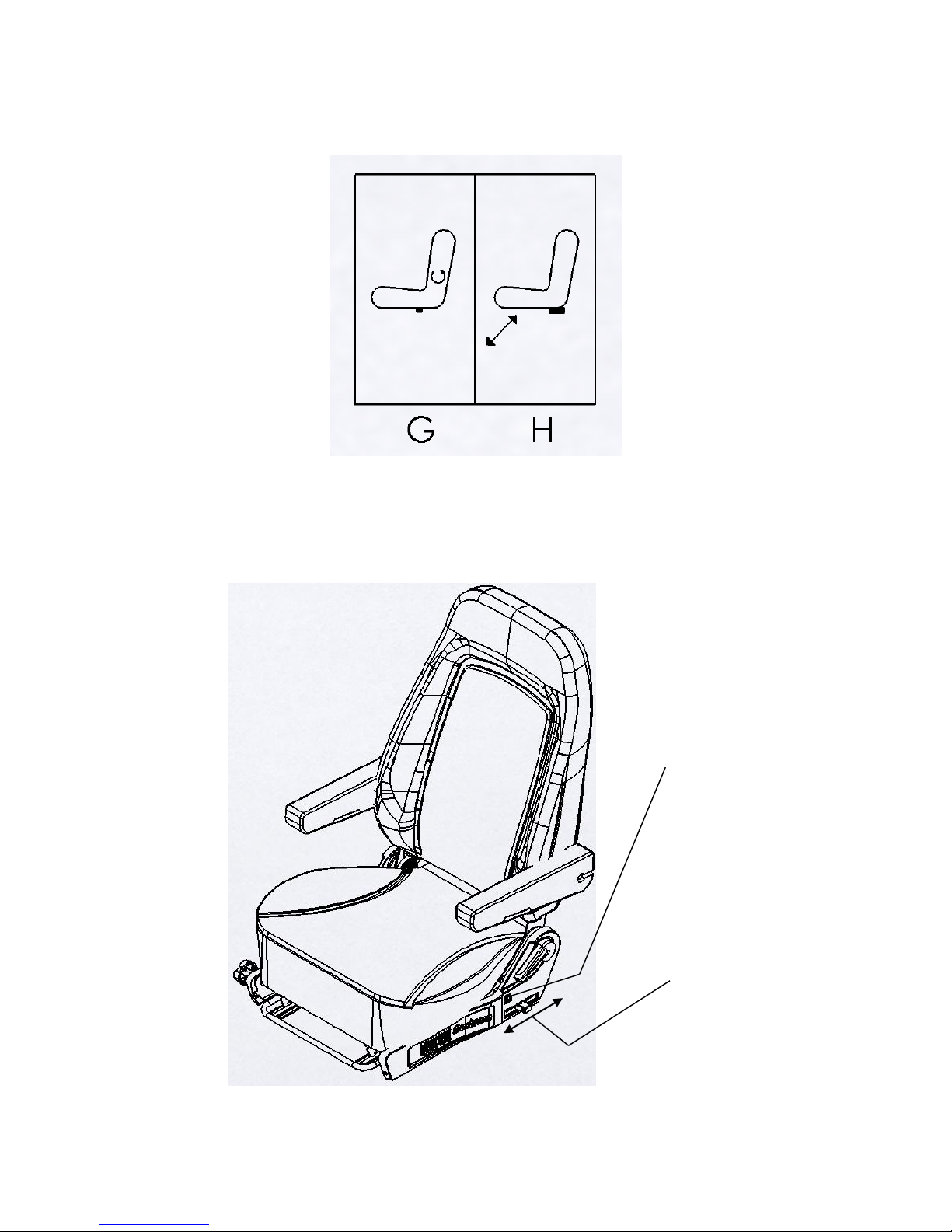
COMFORT ADJUSTMENTS
H- ADJUSTABLE DAMPER
CONTROL
To adjust dampening of
suspension push or pull
damper adjustment handle.
G – BACK CYCLER
To reduce back pain and
fatigue press back cycler
switch, a controlled
bladder inflates and
After installation the following comfort adjustments
can be made to ensure the best performance.
4
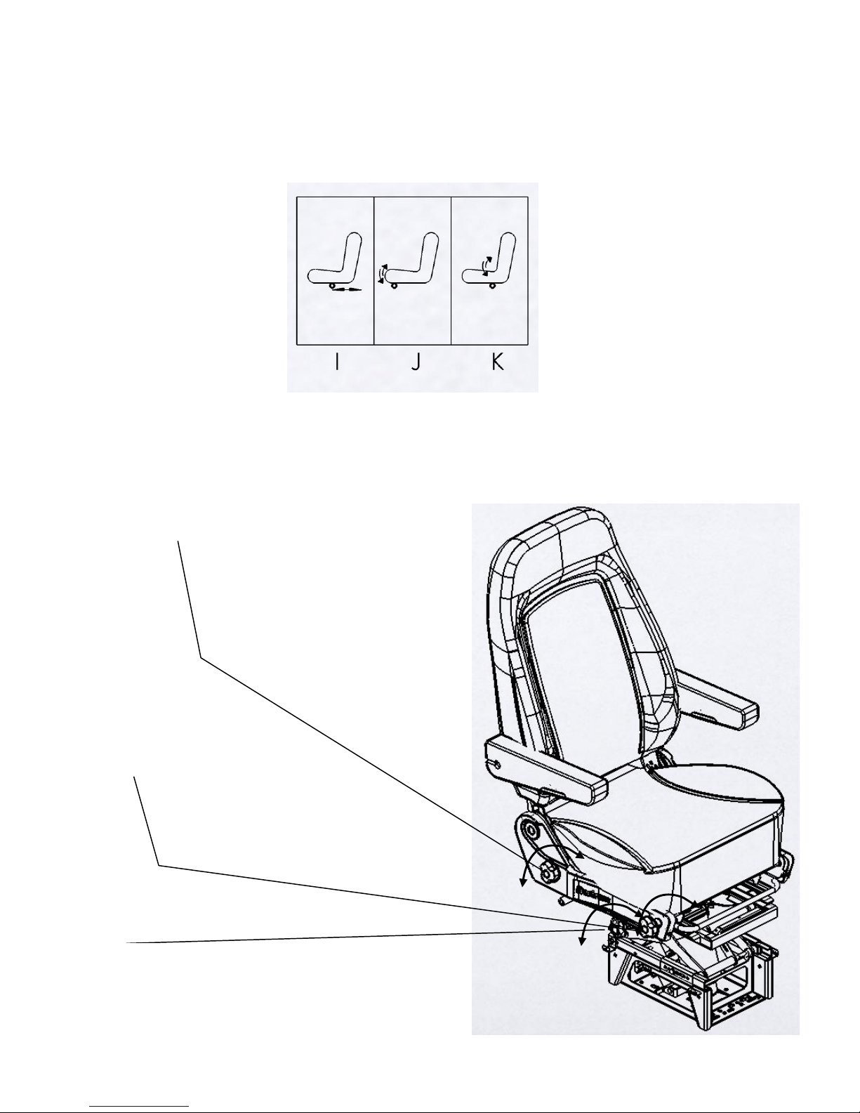
J - SEAT CUSHION
TILT ADJUSTMENT-FRONT
Rotate seat tilt knob
to decrease or
increase front seat tilt.
K - SEAT CUSHION
TILT ADJUSTMENT-REAR
Rotate seat tilt knob
to decrease or
increase rear seat tilt.
I - FORE AND AFT ISOLATION
Isolation is provided
when the knob rotated counter
clock direction
COMFORT ADJUSTMENTS
After installation the following comfort adjustments
can be made to ensure the best performance.
5
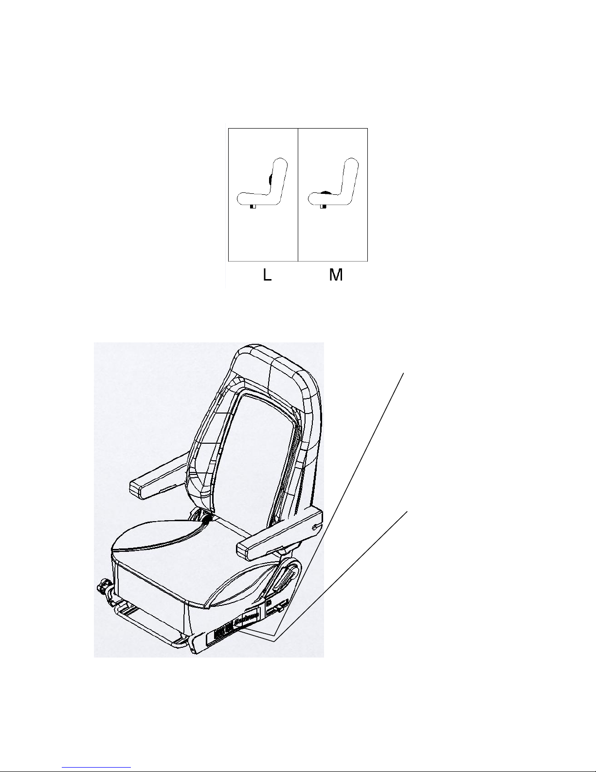
M – CUSHION BOLSTER
To increase cushion bolster
Support, press bolster
switch upward.
To decrease cushion bolster
Support, press bolster
switch downward.
L – BACK BOLSTER
To increase back bolster
Support, press bolster
switch upward.
To decrease back bolster
support, press bolster
switch downward.
COMFORT ADJUSTMENTS
After installation the following comfort adjustments
can be made to ensure the best performance.
6

BOSTROM WIDE RIDE II
▲WARNING
THE VEHICLE IS NOT IN MOTION. WHEN THE VEHICLE IS MOVING, THE SEAT MUST BE LOCKED IN
THE FORWARD FACING POSITION AND THE SEAT BELT WORN FOR MAXIMUM OCCUPANT SAFETY.
N – SWIVEL OPTION
To rotate the top seat push
back swivel handle and
adjust seat with desired
position, then move
swivel handle front for lock.
SEAT SWIVEL OPERATION
THE SWIVEL FEATURE OF THIS SEAT IS INTENDED SOLELY FOR OPERATION WHEN
SWIVEL OPERATION SEQUENCE SUMMARY
1. OUTBOARD ARMREST DOWN
2 . BACK NEAR VERTICAL POSITION
3 . ADJUST FORE/AFT AS REQUIRED
4. CHECK ARM AND BACK CLEARANCE
5. READJUST SEAT AND BACK AS DESIRED
7

BOSTROM WIDE RIDE II
SUSPENSION ASSEMBLY-EXPLODE VIEW
8

ILLUSTRATED PARTS BREAKDOWN
9
ILLUSTRATED PARTS BREAKDOWN
10

ILLUSTRATED PARTS BREAKDOWN
11

ILLUSTRATED PARTS BREAKDOWN
12

ILLUSTRATED PARTS BREAKDOWN
13

ILLUSTRATED PARTS BREAKDOWN
14

ILLUSTRATED PARTS BREAKDOWN
ITEM NO.
DESCRIPTION
PART NUMBER
1
HIGH PROFILE SUSPENSION W/ ISOLATION ASSEMBLY KIT
2421700-001
15

2
TRACK ASSEMBLY KIT
6222288-001
3
DRIVER/PASSENGER SWIVEL ASSEMBLY KIT
6222289-001/002
4
SUSPENSION COVER KIT
6222290-001
5
HIGH BACK FOAM ASSEMBLY KIT
6224840-XXX
6
HIGH BACK FRAME ASSEMBLY KIT
6222291-001
7
CUSHION FRAME SUPPORT ASSEMBLY KIT
6222292-001
8
CUSHION FRAME ASSEMBLY KIT
6222293-001
9
CUSHION FOAM ASSEMBLY KIT
6224725-XXX
10
LUMBAR W/ BACK CYCLER KIT
6222294-001
11
RECLINER ASSEMBLY KIT
6222295-001
12
RECLINER STOP ASSEMBLY KIT
6222296-001
13
TILT KNOB KIT
6222297-001
14
SIDE SHIELD KIT
6222298-001
15
RECLINER HANDLE KIT
6204484-001
16
VALVES AND MANIFOLD KIT
6222299-001
17
MID BACK FOAM ASSEMBLY KIT
6224841-XXX
18
MID BACK FRAME ASSEMBLY KIT
6222316-001
19
ARMREST ASSEMBLY KIT
1234480-XXX
20
ARMREST ATTACHMENT HARDWARE KIT
6222117-001
21
SCISSOR AND ISOLATOR ASSEMBLY KIT
6222315-001
22
HIGH PROFILE RISER ASSEMBLY KIT
6222317-001
23
ADJUSTABLE SHOCK ABSORBER ASSEMBLY KIT
6222311-001
24
AIR SPRING ASSEMBLY KIT
6222318-001
25
SEAT CONTROL CABLE WITH BRACKET ASSEMBLY KIT
6222312-001
26
HIGH PROFILE SUSPENSION W/O ISOLATION ASSEMBLY KIT
2421701-001
27
LOW PROFILE SUSPENSION W/ ISOLATION ASSEMBLY KIT
2321263-001
28
LOW PROFILE SUSPENSION W/O ISOLATION ASSEMBLY KIT
2321264-001
29
SCISSOR AND NON ISOLATOR ASSEMBLY KIT
6222313-001
30
LOW PROFILE RISER ASSEMBLY KIT
6222314-001
16
 Loading...