

Boston gear 710, 715, 713, 718, 721 Installation, Lubrication, Operation Instructions And Parts
...Page 1
Boston Gear
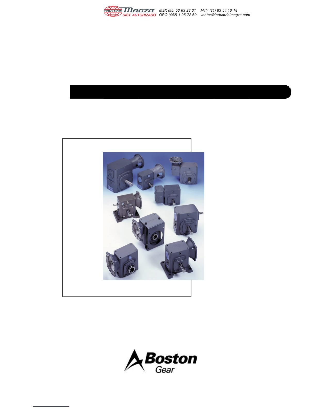
Worm Gear Speed Reducers
Installation, Lubrication, Operation Instructions and Parts
Doc. No. 57746
700 Series
Single and Double
Reductions
®
Page 2
Inadequate lubrication is by far the largest contributor to
premature failures of worm gear drives, applied within proper
selection practice.
While lubricant selection is important to all gear reducers, it is
critical for the worm gear type. Sliding action at the tooth
mesh dictates use of a relatively high viscosity oil with special
characteristics. A recent survey indicated improper lubricants
were used in two-thirds of the applications. Although lightly
loaded drives may survive, optimum performance is not
obtained.
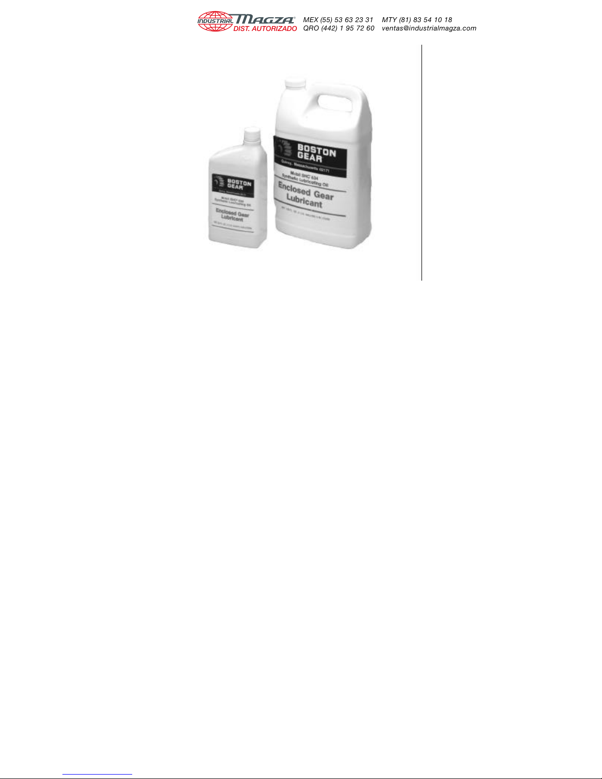
Boston Gear now offers Mobil SHC634 Synthetic Lubricating
Oil as a premium lubricant with many outstanding benefits for
worm gear applications.
• Reduction in maintenance costs due to extended time
between oil changes.
• Increased ratings providing for smaller drive selection or
longer gear life.
• Lower energy consumption from improved efficiency.
• Broad ambient temperature range due to high viscosity
temperature.
• Longer seal life, based on lower operating temperature.
• Multi-purpose application, including most other types of
gear drives.
Lubrication Instructions
Lubrication and maintenance instructions are provided with
each speed reducer. These instructions should be followed for
best results. It is important that the proper type of oil be used
since many oils are not suitable for the lubrication of gears.
Various types of gearing require different types of lubricants.
The lubricant must remain free from oxidation and contamina tion by water or debris, since only a very thin film of oil stands
between efficient operation and failure. To assure long service
life, the reducer should be periodically drained (preferably
while warm) and refilled to the proper level with a recommended gear oil. Under normal environmental conditions oil
changes are suggested after the initial 250 hours or every 6
months.
Synthetic lubricants will allow extended lubrication intervals
due to its increased resistance to thermal and oxidation
degradation. It is suggested that the initial oil change be made
at 1500 hours and, thereafter, at 5000 hour intervals.
During the initial period of operation, higher than normal
operating temperatures may be seen. This is due to the initial
break-in of the worm gear set. The temperature of
Double Reduction Worm Gear Reducers may reach 160°F
and Single Reduction Worm Gear Reducers approximately
225°F.
These instructions must be read thoroughly before
installing or operating speed reducers. File instructions
for future reference and for ordering of replacement
parts.
WARNING - Boston Gear speed reducers are normally
shipped without lubricant. They must be filled to the
proper level with the recommended lubricant for your
application before operation.
The recommended lubricant table indicates the type and
viscosity of lubricant suitable for reducers operating at various
temperatures.
1 Doc. No. 57746 • Boston Gear® 700 Series Worm Gear Speed Reducers
General Instructions
1. Align all shafts accurately. Improper alignment can result
in failure. Use of flexible couplings is recommended to
compensate for slight misalignment.
2. When mounting, use maximum possible bolt size and
secure reducer to a rigid foundation. Periodic inspection
of all bolts is recommended.
Page 3
3. Auxiliary drive components (such as sprockets, gears and
pulleys) should be mounted on the shafts as close as
possible to the housing to minimize effects of overhung
loads. Avoid force fits that might damage bearings or
gears.
4. For hollow-shaft speed reducers, place speed reducer as
close as possible to supporting bearing on drive shaft.
Spot-drill driven shaft for setscrews in severe applications.
See kit instructions for reaction rod assembly.
5. Check and record gear backlash at installation and again
at regular intervals. This should be done by measuring the
rotary movement of the output shaft (rotating alternately
clockwise and counterclockwise) at a suitable radius while
holding the input shaft stationary. Gears should be
replaced when the backlash exceeds four times the
measurement taken at installation.
6. Gear drives are rated for 1750 input RPM and Class I
Service (Service Factor 1.0), using Mobil SHC634
synthetic lubricant. For lower input speeds or for different
service classes or lubricants, see catalog selection pages
for rating information.
7. Initial operating temperatures may be higher than normal
during the break-in period of the gear set. FOR MAXIMUM
LIFE, DO NOT ALLOW THE SPEED REDUCER TO
OPERATE CONTINUOUSLY ABOVE 225°F AT THE
GEAR CASE. In the event of overheating, check for
overloads or high ambient temperatures. Keep shafts and
vent plugs clean to prevent foreign particles from entering
seals or gear housing.
8. All reducers should be checked to see if they have been
lubricated. Prelubed 700 Series reducers will have a solid
plug in the vent hole which must be replaced by the vent
plug at time of installation.
CAUTION – If the motor does not readily seat itself, check
to determine if key has moved axially along motor shaft,
causing interference. Staking of the keyway adjacent to the
motor key will facilitate this procedure.
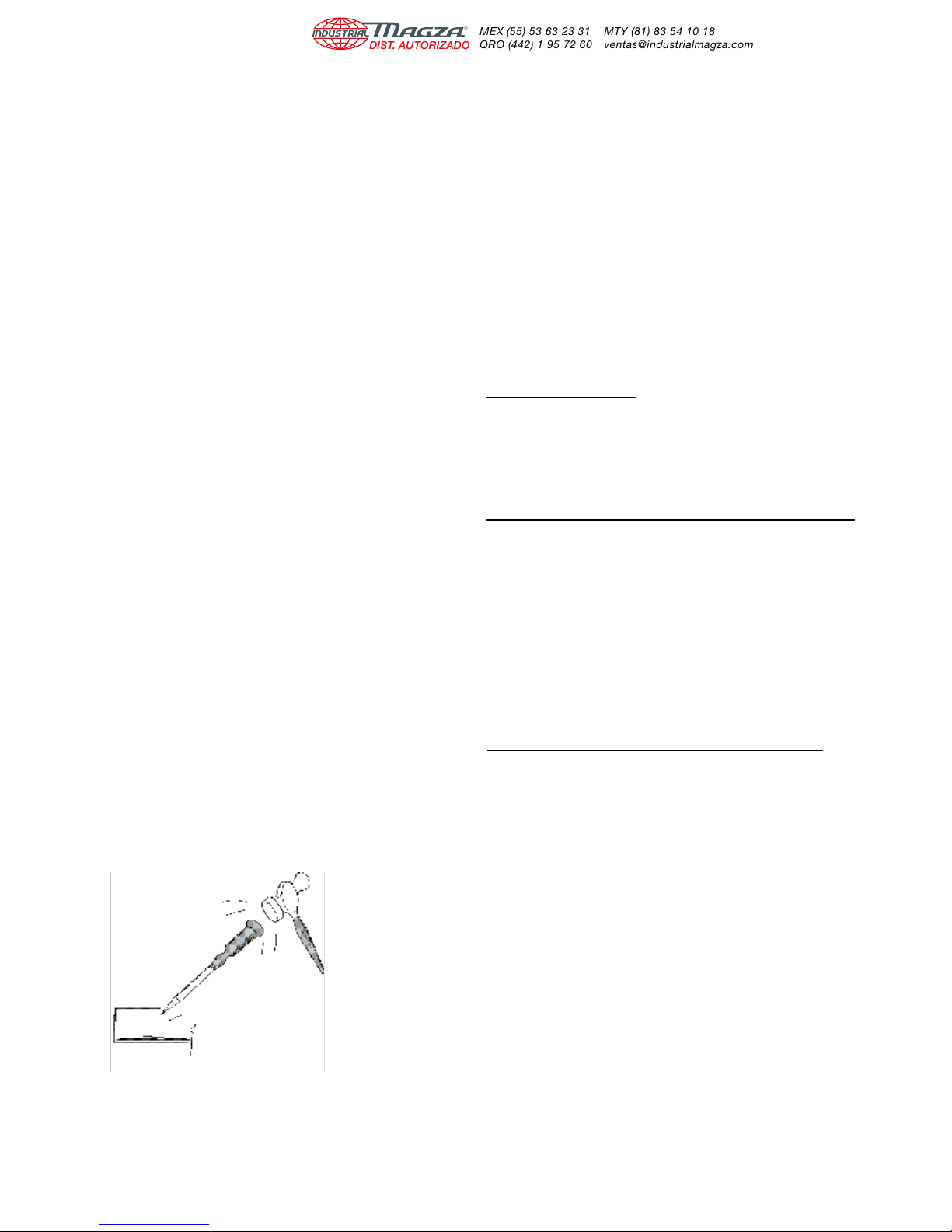
Key Staking Instructions
Lightly tap area of keyway adjacent to key. This will upset
material and not allow key to move axially when assembling to
speed reducer.
CAUTION
• For safe operation of any gear drive, all rotating
shafts and auxiliary components must be shielded
to conform with applicable safety standards. You
must consider overall operational system safety at
all times.
• When using a speed reducer to raise or lower a
load, such as in hoisting applications, provision
must be made for external braking. Under no
conditions should a speed reducer be considered
self-locking.
• Mounting of speed reducers in overhead positions
may be hazardous. Use of external guides or
supports is strongly recommended for overhead
mounting.
Instructions for Flanged Models
F700 (Quill Type Input)
1. Assemble the key to the motor shaft and coat the shaft
with anti-seize compound. Insert the motor shaft into the
reducer input shaft.
2. Rotate the motor to proper position and firmly secure to
flange with four hex-head cap screws.
RF700 (Coupling Input – 3-Jaw Type) (752 and 760 Only)
1. Coat reducer input and motor shaft with anti-seize
compound.
2. Position coupling half on input shaft with shaft flush to end
of coupling bore.
3. Locate remaining half on motor shaft, with 1/32" clearance
between jaw surfaces.
4. Tighten setscrews securely. For reversing applications, a
thread-locking compound is recommended.
5. Install coupling insert and position motor. Rotate motor to
proper position and firmly secure to flange.
QC700 (Coupling Input-3-Jaw Quick Connect Type)
1. Coat motor shaft with anti-seize compound.
2. Install motor coupling half onto motor shaft. Use a straight
edge to align coupling jaw top end flush with motor shaft
except 738-B9 which will be flush with bottom of jaw.
Secure with set screw.
3. Install urethane spider insert on motor coupling half.
4. Insert D-Bore coupling half into urethane spider element.
5. Rotate reducer input shaft so “milled flats” are either
vertical or parallel. Rotate motor coupling D-Bore to match
the reducer milled flats. Coat “D” flats with anti-seize
compound furnished with speed reducer.
Shaft
6. Insert motor assembly into reducer flange assembly.
Minor rotating of the motor may be necessary to facilitate
D-Bore alignment.
7. Once aligned, push motor towards reducer until properly
seated against the face of the reducer flange.
8. Insert (4) hex head cap screws into the designated
locations and securely tightened.
Doc. No. 57746 • Boston Gear® 700 Series Worm Gear Speed Reducers 2
Page 4
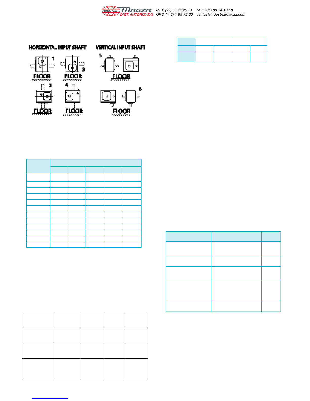
OIL CAPACITIES
SINGLE REDUCTION MODELS ONLY
OILLEVELS FOR TYPICAL MOUNTING POSITIONS
CAUTION - Avoiding those positions where the high
speed oil seal is immersed in oil will provide greater
security against high speed input seal wear.
OIL CAPACITY IN FLUID OUNCES
UNIT
SIZE
710 2.2 3.3 3.3 3.3 3.3
713 5.5 7.0 7.0 7.0 5.5
715 10.0 15.0 15.0 13.5 13.5
718 12.0 16.0 18.5 16.0 16.0
721 15.0 20.5 20.5 19.0 19.0
724 18.0 24.5 28.5 24.5 24.5
726 28.0 36.0 43.0 36.0 36.0
730 44.0 60.0 67.0 60.0 60.0
732 58.0 84.0 90.0 80.0 80.0
738 85.0 120.0 130.0 120.0 107.0
752 204.0 240.0 245.0 240.0 215.0
760 330.0 400.0 415.0 400.0 370.0
1 2 3 4 5 & 6
POSITIONS
DOUBLE REDUCTION MODELS
The variety of mounting possibilities for double reduction
drives makes it impractical to illustrate positions for these
models. In general, the vent filler is at the uppermost plug
position, and the drain plug at the lowest possible position.
The oil level must be at the approximate centerline of the
uppermost gear.
RECOMMENDED LUBRICANTS
ENCLOSEDWORM GEAR REDUCERS
Ambient (Room) Oil Range SUS Lubricant Viscosity
Temperature (or equivalent) @ 100°F AGMA No. Grade No. +
–30° to 225°F** SHC 634* 1950/2150 — — 320/460
(–34° to 107°C) Synthetic
40° to 90°F 600W 1920/3200 7 or 7C 460
(4.4° to 32.2°C) Cylinder Oil
80° to 125°F Hecla Super 2850/3600 8 or 8C 680
(26.7° to 51.7°C) Cylinder Oil
Recommended Viscosity ISO
Mobil
Mobil
Mobil Extra
WORM GEAR LUBRICANTS
AVAILABLE FROM BOSTON GEAR
ORDER BY ITEM CODE
TYPE MOBILSHC 634 MOBIL 600W
SIZE QT. GAL. QT. GAL.
ITEM
CODE
Available in case lots only, i.e.:
12 Qts. / case
6 Gal. / case
51493 51494 27300 51492
CAUTION: Relubricate more frequently if drive operated
in high ambient temperatures or unusually contaminated
atmosphere. High loads and operating temperatures will
also require more frequent lubrication.
*Synthetic recommendation is exclusively for Mobil
SHC634.
+Other lubricants corresponding to AGMA/ISO numbers
are available from all major oil companies.
**The SHC lubricant will perform at temperatures
considerable higher than 225°F. However, the factory
should always be consulted prior to operating at higher
temperature as damage may occur to oil seals and other
components.
LUBRICANT INTERCHANGE
1. Ambient temperature is based upon 1.0 service factor.
2. Lubricants are compounded for use in worm gears. Some
contain non-corrosive, extreme pressure additives. DO
NOT USE lubes that contain sulphur and/or chlorine
which are corrosive to bronze gears. Extreme pressure
lubes, in some cases contain materials that are toxic.
Avoid use of these lubes where they can result in harmful
effects. If in doubt, consult your lube supplier.
MANUFACTURER NAME RATING
Getty Refining Co. Veedol Asreslube 98 8 EP
Getty Refining Co. Veedol Asreslube 95 7 EP
Getty Refining Co. Veedol Asreslube 90 6 EP
Lubrication Engr. Inc. Almasol 609 8
Lubrication Engr. Inc. Almasol 608 7
Mobil Oil Corp. Mobilgear 634 8 EP
Mobil Oil Corp. Mobil Extra Hecla Super 8
Mobil Oil Corp. Mobil Cylinder 600W 7
Shell Oil Co. Omala 460 7 EP
Shell Oil Co. Valvala J460 7
Shell Oil Co. Omala 680 8 EP
Shell Oil Co. Valvala J680 8
Texaco Inc. Meropa 680 8 EP
Texaco Inc. Meropa 460 7 EP
LUBRICANT AGMA
3 Doc. No. 57746 • Boston Gear® 700 Series Worm Gear Speed Reducers
Page 5
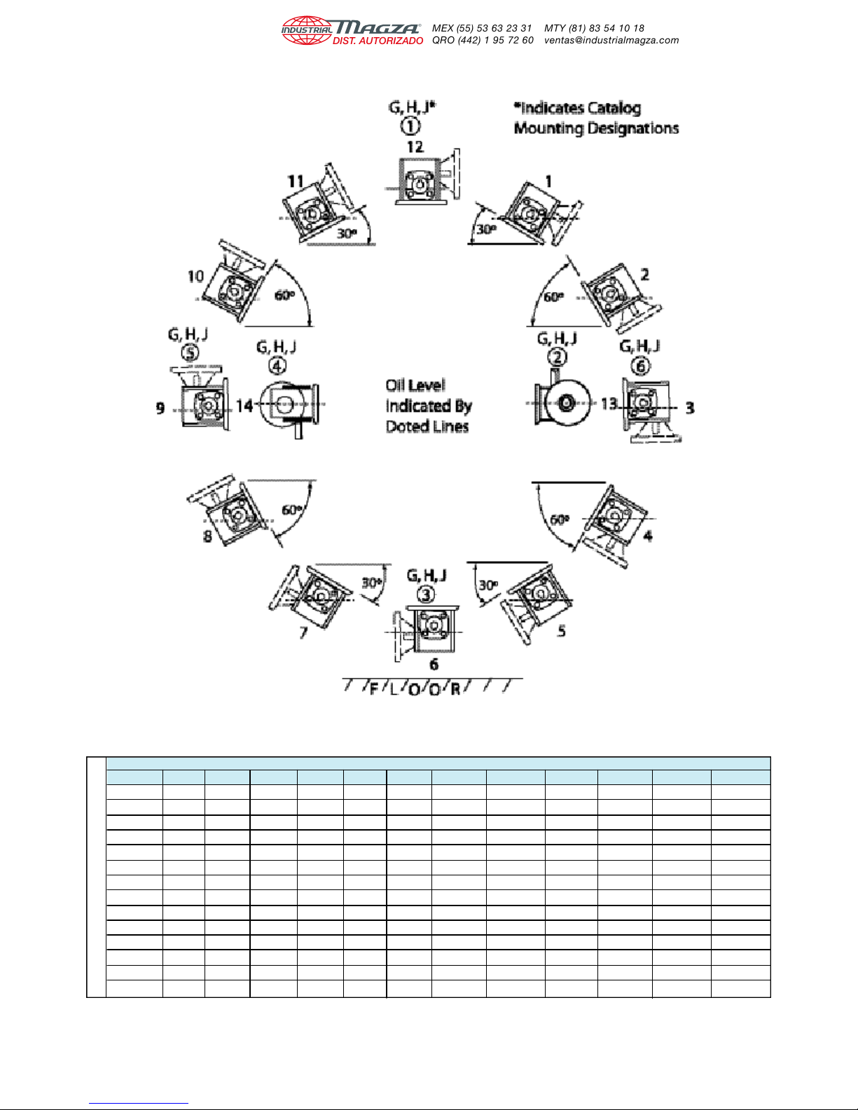
Lubrication Instructions
For single Reduction Only: Refer To Lubrication & Installation Instructions
Position 710 713 715 718 721 724 726 730 732 738 752 760
1 3.00 6.37 9.30 12.85 14.04 16.97 28.50 42.60 56.80 71.60 162.0 255.7
2 3.30 7.16 9.25 15.04 16.81 19.93 32.00 50.00 67.30 79.70 195.2 265.9
3 3.30 5.50 13.50 16.00 19.00 24.50 36.00 60.00 80.00 107.0 215.0 370.0
4 3.55 7.98 12.06 18.00 20.28 24.95 37.70 57.00 77.10 102.0 209.5 321.7
5 3.98 8.18 12.30 18.69 21.45 26.95 40.00 60.40 80.90 106.7 192.0 357.0
6 3.30 7.00 15.00 18.50 20.50 28.50 43.00 67.00 90.00 130.0 245.0 415.0
7 3.98 8.18 12.30 18.69 21.45 26.95 40.00 60.40 80.90 106.7 192.0 357.0
8 3.55 7.96 12.06 18.00 20.28 24.95 37.70 57.00 77.10 102.0 209.5 321.7
9 3.30 5.50 13.50 16.00 19.00 24.50 36.00 60.00 80.00 107.0 215.0 370.0
10 3.31 7.16 9.25 15.04 16.81 19.93 32.00 50.00 67.30 79.70 195.2 265.9
Oil Capacity In Ounces
11 3.00 6.37 9.30 12.85 14.04 16.97 28.50 42.60 56.80 71.60 162.0 255.7
12 2.20 5.50 10.00 12.00 15.00 18.00 28.00 44.00 58.00 85.00 204.0 330.0
13 3.30 7.00 15.00 16.00 20.00 24.50 36.00 60.00 84.00 120.0 240.0 400.0
14 3.30 7.00 13.50 16.00 19.00 24.50 36.00 60.00 80.00 120.0 240.0 400.0
Unit Size
Doc. No. 57746 • Boston Gear® 700 Series Worm Gear Speed Reducers 4
Page 6
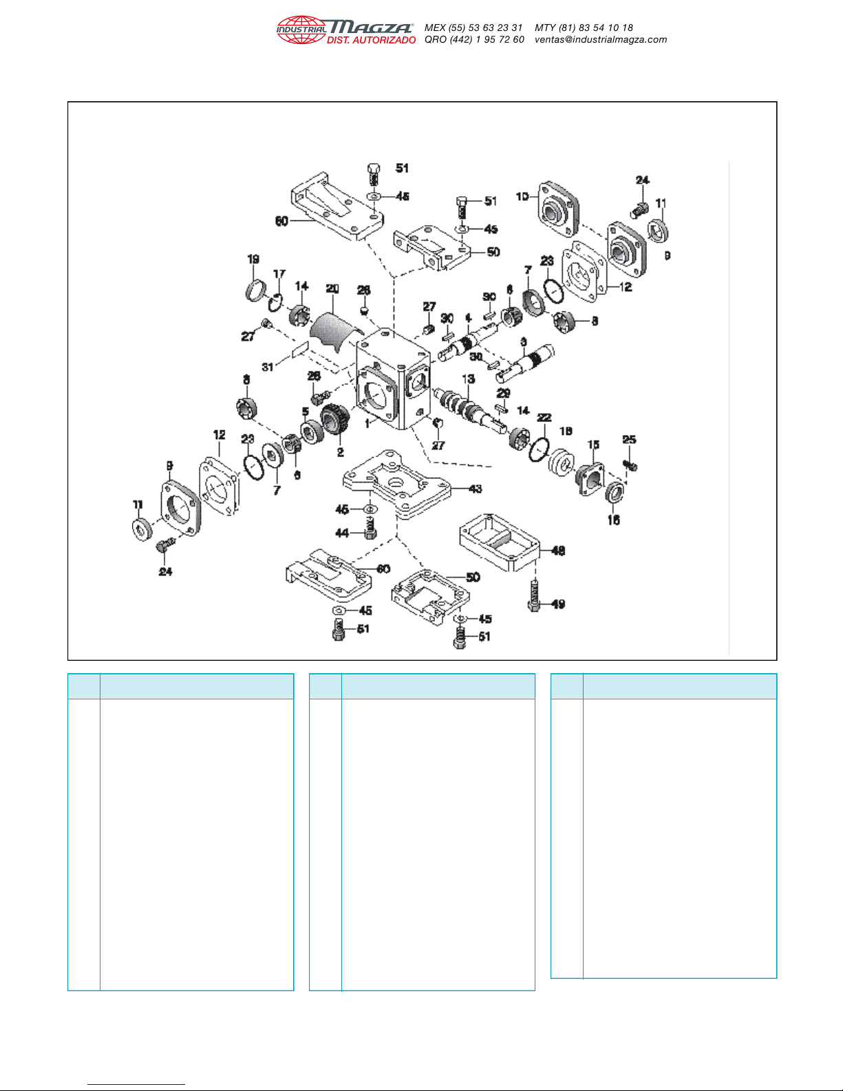
PARTS LIST – SINGLE REDUCTION MODELS
MODELS 710-760
PART
NO.
1 HOUSING
2* WORM GEAR
3* SINGLE PROJECTING OUTPUT SHAFT
4* DOUBLE PROJECTING OUTPUT SHAFT
5* GEAR SPACER
6* OUTPUT BEARING (CONE) – MODELS 713-760
7 OUTPUT BEARING (CUP) – MODELS 713-760
8 OUTPUT BEARING – MODEL 710 ONLY
9 BEARING CARRIER (OPEN)
10 BEARING CARRIER (CLOSED)
11* OUTPUT OIL SEAL
12* ADJUSTMENT SHIMS
13 INPUT WORM SHAFT
14 INPUT BEARING – MODELS 710-730
15 INPUT BEARING RETAINER
16 INPUT OIL SEAL – MODELS 710-760
17 RETAINING RING
18 ADJUSTMENT SHIMS
19 BORE PLUG – MODELS 710-730
20 INTERNAL BAFFLE – MODELS 713-732
22 INPUT “O” RING
23* OUTPUT “O” RING
24 HEX HEAD CAP SCREW
25 HEX HEAD CAP SCREW
26** VENT PLUG – 2 PIECE
27 PIPE PLUG
DESCRIPTION
*For Models 710 to 726, these parts are available as complete assemblies. See Part Ordering Information, page 6.
**Extension not required on single reduction Models 713 through 732.
5 Doc. No. 57746 • Boston Gear® 700 Series Worm Gear Speed Reducers
PART
NO.
28 PROTECTIVE CAP PLUG
29 INPUT KEY
30 OUTPUT KEY
31 NAMEPLATE
32 INPUT BEARING (CUP) – MODELS 732-760
33 INPUT BEARING (CONE) – MODELS 732-760
34 GREASE CUPS – MODELS 732-760
35 HEX HEAD CAP SCREW
37 OUTPUT SHAFT KEY – MODELS 730-760
38 RETAINING RING – MODELS 710-738
39 MOTOR SHAFT – MODELS 710-738
40 MOTOR FLANGE – MODELS 710-738
41 OIL SEAL – MODELS 710-738
42 HEX HEAD CAP SCREW
43 HORIZONTAL BASE
44 HEX HEAD CAP SCREW
45 LOCKWASHER
46 2 PIECE COUPLING – WITH INSERT
47 RETAINING MOTOR FLANGE
48 RISER BLOCK
49 HEX HEAD CAP SCREW
50 VERTICAL BASE (HIGH OR LOW)
51 HEX HEAD CAP SCREW
60 VERTICAL BASE (X & Y ASSEMBLY)
101 FAN
102 SPACER
DESCRIPTION
PART
NO.
103 HEX HEAD CAP SCREW
104 FAN GUARD
105 HEX HEAD CAP SCREW
106 WASHER
165 HOLLOW OUTPUT SHAFT (S VERSION ONLY)
166 HOLLOW OUTPUT SHAFT (H VERSION ONLY)
167 WORM GEAR
168 OUTPUT BEARING (CONE)
169 OUTPUT BEARING (CUP)
170 OIL SEAL
171 BEARING CARRIER S/A
172 HOLLOW SHAFT MTG. BRACKET
173 HEX HEAD CAP SCREW
174 LOCKWASHER
175 KEY (EXTERNAL)
176 KEY (INTERNAL)
177 “V” TYPE BASE
178 SOCKET SETSCREW
DESCRIPTION
Page 7
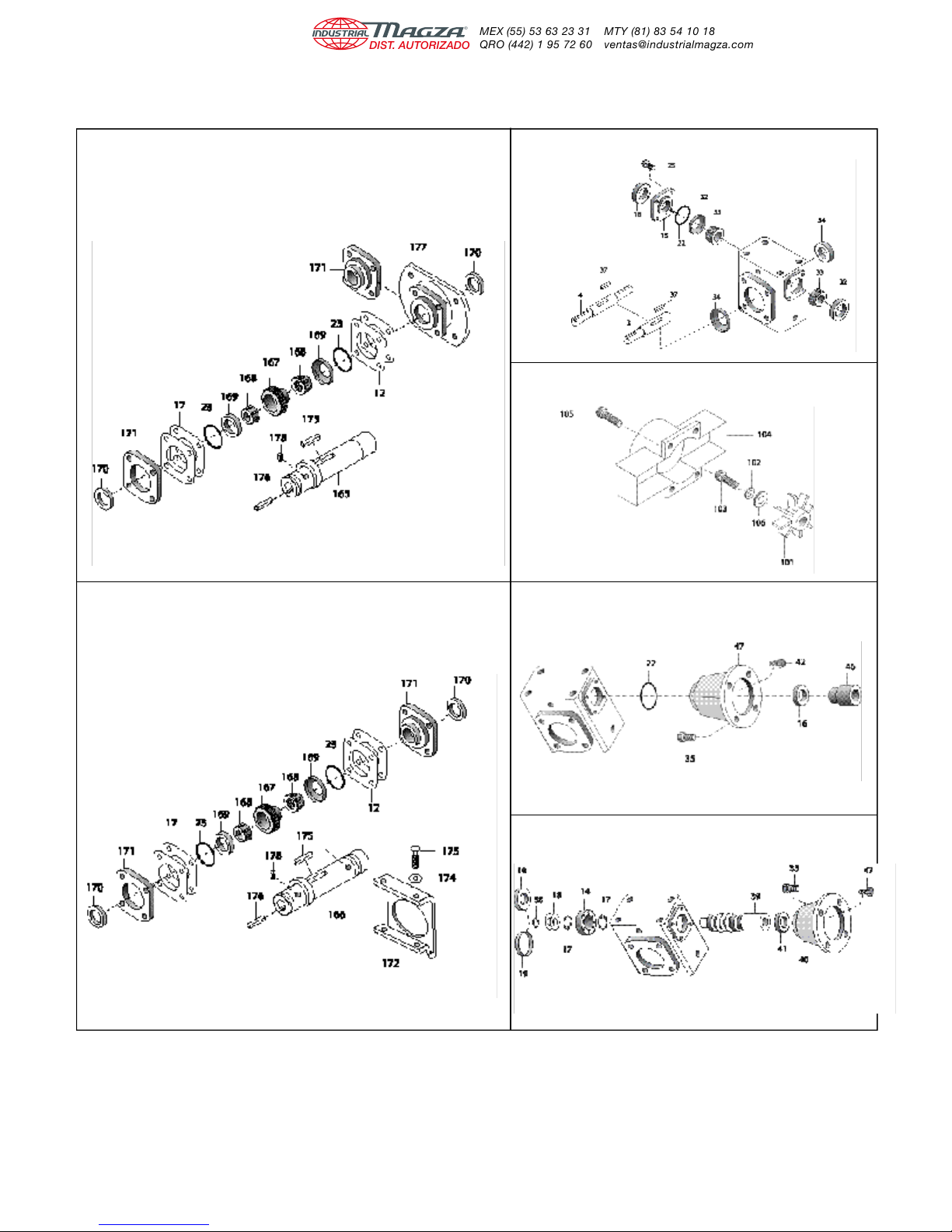
OPTIONS & ACCESSORIES – SINGLE REDUCTION MODELS
HOLLOW OUTPUT MODELS 732-760
SHAFT MODELS
S AND SF718-732
MODEL 02
FAN KIT FOR MODELS 732-760
HOLLOWOUTPUT MODELS QC710-QC738, RF710-RF760
SHAFT MODELS
H, HF, HRF AND HQC713-738
MODELS F710-F738
PART ORDERING INFORMATION
1.Be sure to provide complete Boston Gear catalog number from speed reducer nameplate, along with part description and number. For example,
“One output oil seal, Part No. 11, for F718-30-B5-G”.
2.Output shaft components for Boston Gear models 710 through 726 are available only as complete assemblies that include Parts 2, 3, 5, 6, 11, 12
and 23 for single projecting shafts; and Parts 2, 4, 5, 6, 11, 12 and 23 for double projecting shafts. When ordering, specify “output shaft assembly”
and full Boston Gear catalog number from nameplate.
Doc. No. 57746 • Boston Gear® 700 Series Worm Gear Speed Reducers 6
Page 8
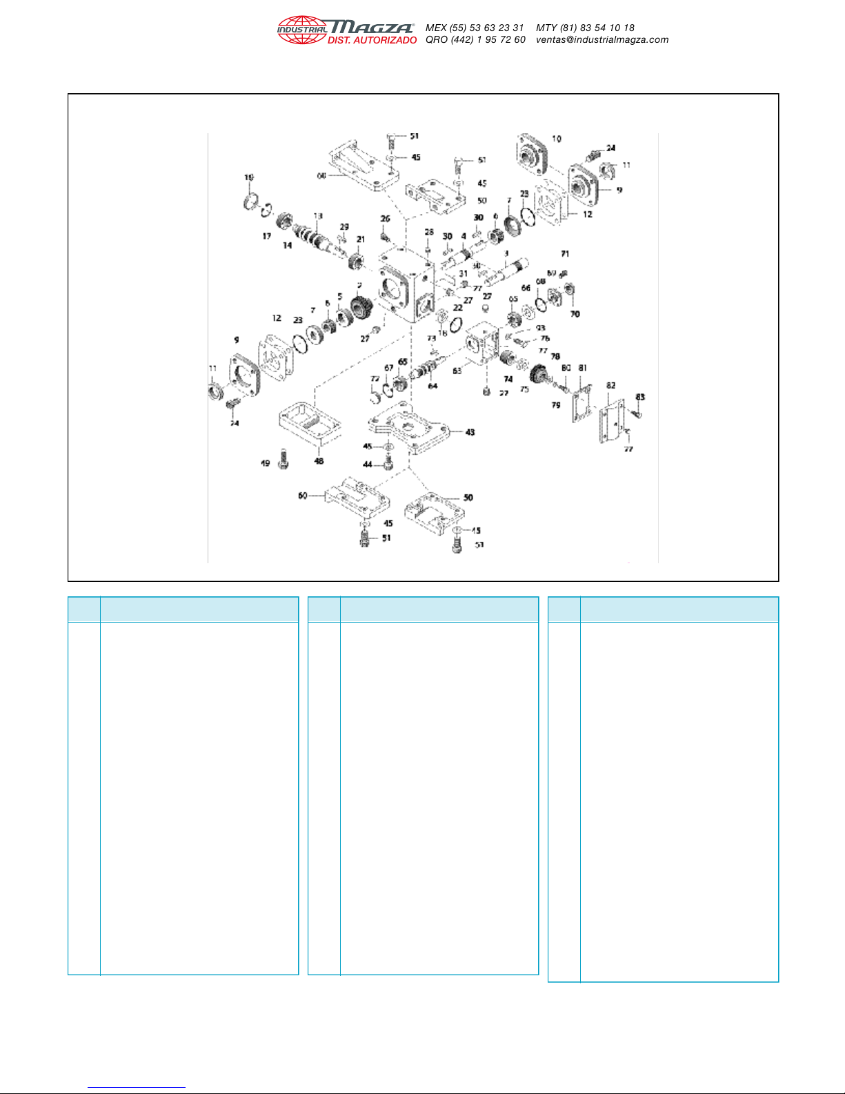
PARTS LIST – DOUBLE REDUCTION MODELS
MODELS W713-W760
PART
NO.
1 HOUSING
2* WORM GEAR
3* SINGLE PROJECTING OUTPUT SHAFT
4* DOUBLE PROJECTING OUTPUT SHAFT
5* GEAR SPACER
6* OUTPUT BEARING (CONE)
7 OUTPUT BEARING (CUP)
8 OUTPUT BEARING – MODEL 710 ONLY
9 BEARING CARRIER (OPEN)
10 BEARING CARRIER (CLOSED)
11* OUTPUT OIL SEAL
12* ADJUSTMENT SHIMS
13 INTERMEDIATE WORM SHAFT
14 INTERMEDIATE BEARING–MODELS W713-W730
15 INTER. BEARING RETAINER–MODELS W732-760
16 INTER. OIL SEAL – MODELS W732-W760
17 RETAINING RING – MODELS W713-W730
18 ADJUSTMENTS SHIMS
19 BORE PLUG – MODELS W713-W730
21 INTERMEDIATE BEARING
22 INTERMEDIATE “O” RING
23* OUTPUT “O” RING
24 HEX HEAD CAP SCREW
25 HEX HEAD CAP SCREW
26 VENT PLUG – 2 PIECE
27 PIPE PLUG
28 PROTECTIVE CAP PLUG
29 INTERMEDIATE KEY
30 OUTPUT KEY
31 NAMEPLATE
32 INTER. BEARING (CUP) – MODELS W732-W760
DESCRIPTION
PART
NO.
33 INTER. BEARING (CONE) – MODELS W732-W760
34 GREASE CUPS – MODELS W732-W760
35 HEX HEAD CAP SCREW
37 OUTPUT SHAFT KEY – MODELS W730-W760
43 HORIZONTAL BASE
44 HEX HEAD CAP SCREW
45 LOCKWASHER
48 RISER BLOCK
49 HEX HEAD CAP SCREW
50 VERTICAL BASE (HIGH OR LOW)
51 HEX HEAD CAP SCREW
60 VERTICAL BASE (ASSEMBLY X & Y)
63 ATTACHMENT HOUSING
64 INPUT WORM SHAFT
65 INPUT BEARING
66 ADJUSTMENT SHIMS
67 RETAINING RING
68 “O” RING
69 BEARING RETAINER
70 OIL SEAL
71 HEX HEAD CAP SCREW
72 BORE PLUG – MODELS W713-W738
73 INPUT WORM SHAFT KEY
74 GEAR SPACER
75 ADJUSTMENT SHIMS
76 HEX HEAD CAP SCREW
77 INTERMEDIATE WORM GEAR
78 WASHER
79 LOCKWASHER
80 HEX HEAD CAP SCREW
81 ATTACHMENT COVER GASKET
DESCRIPTION
*For Models 710 to 730, these parts are available as complete assemblies. See Part Ordering Information, Page 8.
PART
NO.
82 ATTACHMENT COVER
83 HEX HEAD CAP SCREW
84 INPUT BEARING (CONE) – MODEL W760 ONLY
85 INPUT BEARING (CUP) – MODEL W760 ONLY
86 TWO PIECE COUPLING WITH INSERT
87 MOTOR FLANGE
88 HEX HEAD CAP SCREW
89 MOTOR FLANGE
90 INPUT WORM SHAFT
91 EXTERNAL RETAINING RING
92 OIL SEAL – MODELS FW713-FW738
93 WASHER
165 HOLLOW OUTPUT SHAFT (S VERSION ONLY)
166 HOLLOW OUTPUT SHAFT (H VERSION ONLY)
167 WORM GEAR
168 OUTPUT BEARING (CONE)
169 OUTPUT BEARING (CUP)
170 OIL SEAL
171 BEARING CARRIER
172 HOLLOW SHAFT MTG. BRACKET
173 HEX HEAD CAP SCREW
174 LOCKWASHER
175 KEY (EXTERNAL)
176 KEY (INTERNAL)
177 “V” TYPE BASE
178 SOCKET SETSCREWS
DESCRIPTION
7 Doc. No. 57746 • Boston Gear® 700 Series Worm Gear Speed Reducers
Page 9
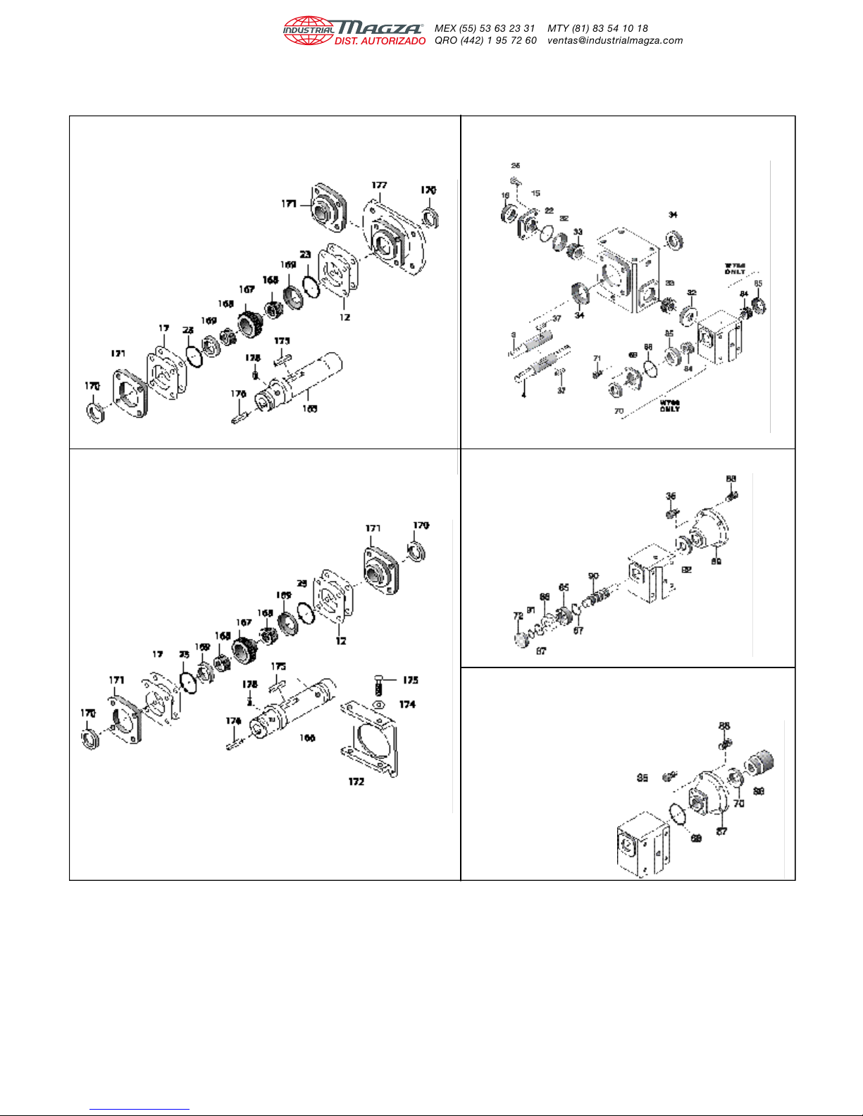
OPTIONS & ACCESSORIES – DOUBLE REDUCTION MODELS
HOLLOW OUTPUT MODELS W732-W760
SHAFT MODELS PARTS ADDED TO W732-W760
SW, SFW, and
SRFW718-732
MODEL 02
HOLLOW OUTPUT MODELS FW713-FW752
SHAFT MODELS PARTS ADDED TO W713-W752.
HW, HFW, HRFW and HQCW713-738
PART ORDERING INFORMATION
1.Be sure to provide complete Boston Gear catalog number from speed reducer nameplate, along with part description and number. For example,
“One output oil seal, Part No. 11, for W713-150-G”.
2.Output shaft components for Boston Gear models 710 through 726 are available only as complete assemblies that include Parts 2, 3, 5, 6, 11, 12
and 23 for single projecting shafts; and Parts 2, 4, 5, 6, 11, 12 and 23 for double projecting shafts. When ordering, specify “output shaft assembly”
and full Boston Gear catalog number from nameplate.
MODELS QCW713-QCW760,
RFW710-RFW760
PARTS ADDED TO
W713-W726 OR
W732-W760. THESE
PARTS AVAILABLE
IN KIT FORM.
Doc. No. 57746 • Boston Gear® 700 Series Worm Gear Speed Reducers 8
Page 10
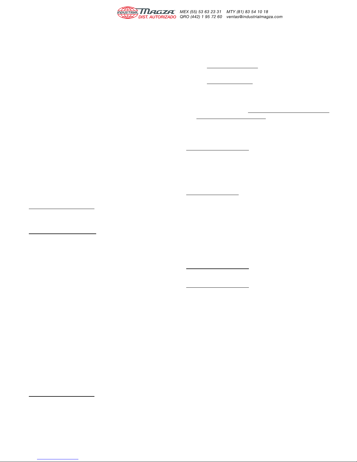
F700 Series
Disassembly and Re-assembly Procedure
(For Item Identification, Refer To Exploded View)
Output Shaft Disassembly
1. Remove vented filler (Item 26), and the most convenient
pipe plug (Item 27) and completely drain oil.
2. Remove bearing carrier screws (Item 24) from projecting
shaft bearing carrier (Item 9). Remove carrier by
CAREFULLY sliding it over the projecting shaft diameter.
3. Output shaft assembly (Items 2, 3, 5 & 6) can now be
removed from the unit. Exercise care not to nick or
scratch worm gear or shaft diameters.
4. Visually examine the output shaft assembly. Check
tapered roller bearings (Item 6) for signs of metallic
contamination or discoloration. Rollers should have
continuously smooth action and should not bind or exhibit
“flat-spots”.
5. Note that replacement parts for output gear (Item 2) will
include an output shaft assembly (Items 3 OR 4) for sizes
F710 through F726. Also included are items 5, 6, 11, 12
and 23.
Input Shaft Disassembly
Models F710 through F730
1. With a screwdriver or suitable tool, pierce the bore plug
(Item 19) and remove from the housing bore.
Models F732 and F738 only
2. Remove fan guard (Item 104). Remove fan retaining
screw (Item 103), fan (Item 101) and spacer. With a
screw-driver or suitable tool, pierce and fan end oil seal
(Item 16) and remove from the housing bore.
3. Remove the outboard retaining ring (Item 17) from the
housing bore. Remove the metal shims (Item 18), located
between the retaining ring and the ball bearing (Item 14).
4. Remove four (4) screws (Item 42) from the motor flange
(Item 40) and remove the flange from the housing.
5. Remove the input worm assembly (Items 14, 38 and 39)
through the bore opposite the flange side. Remove the oil
seal (Item 41) from the housing.
6. Check the condition of the ball bearing (Item 14). The
bearing should roll smoothly and not bind. If the bearing
needs replacement, remove the snap ring (Item 38) and
press the shaft through the bearing.Install new bearing
onto the shaft and re-assemble the snap ring. If the
bearing is not pre-packed with grease, pack at least 50%
full with MOBILUX EP #2 ALL PURPOSE GREASE or
equivalent.
Input Shaft Re-Assembly
Models F710 through F738
1. Insert input worm assembly in the housing. Seat the ball
bearing against the inner retaining ring (Item 17).
2. Install the metal shims (Item 18) and assemble outboard
snap ring (Item 17).
3. Clean the housing bore(s) in the area where oil seals will
be installed.
4. Coat the oil seals as follows:
A. Rubber Clad Oil Seals - Apply ALL-PURPOSE
grease (NLGI #2 consistency) to the I.D and O.D.
B. Steel Clad Oil Seals - Apply ALL-PURPOSE grease
to the ID only and coat the bore evenly with
Permatex Form-A-Gasket #3 sealant or equivalent.
5. Insert the new oil seal (Item 41) over the shaft until it
contacts the housing. CARE MUST BE TAKEN NOT TO
DAMAGE THE OIL SEAL LIP.
6. With a small hammer, tap around the face of the oil seal
casing - near the outside diameter. Locate the seal as
shown in Figure 2 Page 14. Use a suitable driving tool.
Model F710 through F730
7. Install a new bore plug (Item 19). Coat the bore with
PERMATEX FORM-A-GASKET #3 OR EQUIVALENT
SEALANT. Using a small hammer, lightly tap around the
plug face near the outside diameter. CAUTION should be
exercised not to distort or cock the bore plug.
Model F732 and F738
8. Install new oil seal on the fan end (Item 16). With a small
hammer, tap around the face of the oil seal casing - near
the outside diameter. Use a suitable tool to assure
squareness of the seal to the bore. Drive the seal flush to
1/16th inch projection. Reinstall fan spacer, fan, washer,
lockwasher, and bolt. Tighten the bolt per the chart in
Figure 5, Page 15. Reinstall the fan guard and tighten the
screws per chart in Figure 5.
Worm Gear Replacement
Model F710 through F726
1. Replace the entire output assembly.
Model F730 through F760
2. Place the output gear assembly into a pressing fixture
and remove the worm gear from the shaft.
3. With the gear key assembled in the shaft key seal, press
the new gear onto the shaft to the dimension shown in
Figure 1, Page 14.
4. Install the shaft spacer (Item 5) and grease cups (Item
34).
5. Press the bearing cones (Item 6) onto the shaft making
sure that the assembly is tight (no space between items).
6. Remeasure from the end of the shaft to the gear face as
shown in Figure 1, Page 14. Readjust, if necessary, by
pressing on the bearing cone until desired dimension is
achieved.
7. Where grease cups are used, pack with Mobilux EP #2
All-purpose grease or equivalent.
9 Doc. No. 57746 • Boston Gear® 700 Series Worm Gear Speed Reducers
Page 11
Output Shaft Re-assembly Into Housing
1. Remove the existing oil seal (Item 11) from the bearing
carrier (Item 9).
2. Coat the gear teeth with blue or red Dykme mixture or
similar coating and install the output assembly into the
housing.
3. Slide the bearing carrier over the projecting shaft and bolt
the carrier to the housing, making sure the metal shims
(Item 12) are between the carrier and the housing. Rotate
the input shaft to properly seat the tapered bearings.
4. Shim adjustment must be made at this time. If the output
shaft is excessively loose, measure the endplay of the
output shaft and remove shims evenly from BOTH
carriers until the endplay is within the limits shown in
Figure 3, Page 15.
If the carrier does NOT meet the housing face, measure
the gap and add shims evenly to BOTH carrier locations
until the endplay is within the limits specified.
5. ASSEMBLE THE MOTOR TO THE UNIT. Check the
worm gear centrality. Apply a slight load on the output
shaft then rotate the input shaft for one to two minutes.
Remove the bearing carrier and remove the gear shaft
assembly. Check the gear teeth for correct bearing
pattern as shown in Figure 6, Page 16.
6. If adjustment is required, all adjustments MUST be made
to the carrier which is located on the side OPPOSITE the
GEAR HUB. All adjustment for centrality must be made
from the TOTAL shim pack which has already been
determined.
Example: If a shim is REMOVED from the centralized side, it
must be ADDED to the opposite side.
7. When a good bearing pattern has been established,
assemble carrier(s) to the unit. Replace all O-rings (Item
23) where required. (Install all shims on the carriers
BEFORE installing O-rings). If replacement O-rings are
not available, apply a large bead of Permatex FORM-AGASKET #3 or equivalent on the pilot diameter and
flange.
8. Install a new oil seal (Item 11) into the carrier bore. Use
procedures as described above. Press the seal flush to
1/16th inch projecting. Install the carrier over the
projecting shaft (recommend placing masking tape over
the sharp edges of the shaft keyseat to prevent cutting
the oil seal lip).
9. Tighten all screws as shown in Figure 5, Page 15.
10. Fill the unit to the proper oil level with the recommended
lubricant.
11. Install the vent plug (Item 26) and the drain pipe plug
(Item 27).
700, QC700 And RF700 Series Flanged
Disassembly and Re-assembly Procedure
(For Item Identification, Refer To Exploded View)
Output Shaft Disassembly
1. Remove vented filler (Item 26) and the most convenient
pipe plug (Item 27) and completely drain oil.
2. Remove bearing carrier screws (Item 24) from projecting
shaft bearing carrier (Item 9). Remove carrier by
CAREFULLY sliding it over the projecting shaft diameter.
3. Output shaft assembly (Items 2, 3, 5 & 6) can now be
removed from the unit. Exercise care not to nick or
scratch worm gear or shaft diameters.
4. Visually examine the output shaft assembly. Check
tapered roller bearings (Item 6) for signs of metallic
contamination or discoloration. Rollers should have
continuously smooth action and should not bind or exhibit
“flat-spots”.
5. Note that replacement parts for output gear (Item 2) will
include an output shaft (Items 3 OR 4) for sizes QC/710
through QC/726.
Input Shaft Disassembly
Model RF/QC710 through RF/QC730
1. With a screwdriver or suitable tool, pierce the bore plug
(Item 19) and remove from the housing.
2. Remove the snap ring (Item 17) from the housing.
Remove the retainer at the projecting shaft (Item 15) and
the shims (Item 18).
3. With a soft mallet, tap lightly on the projecting shaft,
removing the shaft assembly from the bore plug end.
4. Check the condition of the ball bearings (Item 14). The
bearing should roll smoothly and not bind. If the bearing
needs replacement, press the shaft through the bearing.
Install new bearings on the shaft. Install bearings so that
the shields face inward. If the bearing is not prepacked
with grease, pack at least 50% full with MOBILUX EP #2
ALL-PURPOSE GREASE or equivalent.
Model QC/RF732 through QC/RF760
5. Remove the fan guard (Item 104). Remove the fan
retaining screw (Item 103), fan (Item 101), and spacer.
Remove the retainer(s) (Item 15) at both ends, if
applicable or remove the motor flange (Item 47) and
shims (Item 18) and O-ring (Item 22).
6. With a soft mallet, tap lightly on the projecting shaft,
removing the bearing cup and input shaft through the fan
end.
7. Remove the bearing cup from the projecting shaft end.
8. Check the conditions of the bearing cones and cups
(Items 32 and 33). The rollers should not exhibit pitting.
The cage should show no wear or distortion. The
bearings, when supported in the cups, should run
smoothly with no binding.
Doc. No. 57746 • Boston Gear® 700 Series Worm Gear Speed Reducers 10
Page 12
9. If the bearings need replacement, press the shaft through
the bearing. Hand-pack the new cones with grease and
install onto the shafts.
Input Shaft Reassembly
Model RF/QC710 through RF/QC730
1. Install the retaining ring (Item 17) in the outboard housing
groove. Install the input shaft assembly through the
projecting shaft end of the housing. Tap lightly to seat the
bearing against the snap ring retainer.
2. Remove the old oil seal (Item 16) from the bearing
retainer (Item 15). Using a small hammer, install a new oil
seal by tapping around the face of the seal casing - near
the outside diameter. The seal should be flush to 1/16th
projection above the retainer surface.
3. Install the bearing cup (Item 32) and shims (Item 18), the
bearing retainer (Item 15) and the O-ring (Item 22). If no
replacement O-ring is available, apply a heavy bead of
PERMATEX FORM-A-GASKET #3 or equivalent in the
housing groove and also form a fillet at the retainer pilot
diameter and flange. It is recommended to protect the oil
seal lip by using masking tape on the keyseat edges.
Model RF/QC732 through RF/QC760
4. Install a new oil seal in the far retainer (Item 16). With a
small hammer, tap around the face of the oil seal casing near the outside diameter. Use a suitable tool to assure
squareness of the seal to the bore. Drive the seal flush to
1/16th inch projection.
5. Repack the roller bearings (Items 32 and 33) or replace if
required.
6. Reinsert the input shaft assembly, assuring that the far
bearing cup (Item 32) is in place. Lightly tap the end of
the projecting shaft to seat the bearing.
7. Insert the front bearing cup (Item 32) and the shim pack.
Replace the front oil seal in the retainer as per step #4
above.
8. Reinstall the front retainer using the O-ring or Permatex.
Tighten all bolts per table Figure 5, Page 15.
9. Rotate the shaft several times to seat the bearings and
check for shaft endplay per Figure 4, Page 15. Adjust if
required.
10. Replace fan and fan guard. Tighten bolts per Figure 5,
Page 15.
Worm Gear Replacement
Model RF/QC710 through RF/QC726
1. Replace the entire output assembly.
Model RF/QC730 through RF/QC760
2. Place the output gear assembly into a pressing fixture
and remove the worm gear from the shaft.
3. With the gear key assembled in the shaft key seat, press
the new gear onto the shaft to the dimension shown in
Figure 1, Page 14.
4. Install the shaft spacer (Item 5) and grease cups (Item
34).
5. Press the bearing cones (Item 6) onto the shaft making
sure that the assembly is tight (no space between items).
6. Remeasure from the end of the shaft to the gear face as
shown in Figure 1, Page 14. Readjust, if necessary, by
pressing on the bearing cone until desired dimension is
achieved.
7. Where grease cups are used, pack with Mobilux EP #2
All-purpose grease or equivalent.
Output Shaft Reassembly Into Housing
1. Remove the existing oil seal (Item 11) from the bearing
carrier (Item 9).
2. Coat the gear teeth with blue or red Dykme mixture or
similar coating and install the output assembly into the
housing.
3. Slide the bearing carrier over the projecting shaft and bolt
the carrier to the housing, making sure the metal shims
(Item 12) are between the carrier and the housing. Rotate
the input shaft to properly seat the tapered bearings.
4. Shim adjustment must be made at this time. If the output
shaft is excessively loose, measure the endplay of the
output shaft and remove shims evenly from BOTH
carriers until the endplay is within the limits shown in
Figure 4. If the carrier does NOT meet the housing face,
measure the gap and add shims evenly to BOTH carrier
locations until the endplay is within the limits specified.
5. Check the worm gear centrality. Apply a slight load on the
output shaft and rotate the input shaft for one to two
minutes. Remove the bearing carrier and remove the
gear shaft assembly. Check the gear teeth for correct
bearing pattern as shown in Figure 6, Page 16.
6. If adjustment is required, all adjustments MUST be made
to the carrier which is located on the side OPPOSITE the
GEAR HUB. All adjustment for centrality must be made
from the TOTAL shim pack which has already been
determined.
Example: If a shim is REMOVED from the centralized side, it
must be ADDED to the opposite side.
7. When a good bearing pattern has been established,
assemble carrier(s) to the unit. Replace all O-rings (Item
23) where required. (Install all shims on the carriers
BEFORE installing O-rings). If replacement O-rings are
not available, apply a large bead of Permatex FORM-AGASKET #3 or equivalent on the housing face and also
form a fillet at the carrier pilot diameter and flange.
8. Install a new oil seal (Item 11) into the carrier bore. Use
procedures as described above. Press the seal flush to
1/16th inch projecting. Install the carrier over the
projecting shaft (recommend placing masking tape over
the sharp edges of the shaft keyseat to prevent cutting
the oil seal lip).
9. Tighten all screws as shown in Figure 5, Page 15.
10. Fill the unit to the proper oil level with the recommended
lubricant.
11. Install the vent plug (Item 26) and the drain pipe plug
(Item 27).
11 Doc. No. 57746 • Boston Gear® 700 Series Worm Gear Speed Reducers
Page 13
FW713 - FW752 Series
Disassembly and Re-assembly Procedure
(For Item Identification, Refer To Exploded View)
Output Shaft Disassembly
1. Remove vented filler (Item 26), and the most convenient
pipe plug (Item 27) and completely drain oil.
2. Remove bearing carrier screws (Item 24) from both
bearing carriers (Items 9 &10). Remove both carriers.
Note: Carefully slide open carrier (Item 9) over projecting
shaft diameter.
3. Output shaft assembly (Items 2, 3, 5 & 6) can now be
removed from unit. Exercise care not to nick or scratch
worm gear or shaft diameters.
4. OUtput shaft assembly can now be visually examined.
Check tapered roller bearings (Item 6) for signs of any
metallic contamination or discoloration. Rollers should
have continuously smooth action and should not bind or
exhibit “flat-spots”.
Intermediate Worm Shaft Disassembly
Models FW713 - FW730
1. With a screwdriver or other similar tool, pierce input bore
plug (Item 19) and remove from housing bore.
Models FW732 - FW752
Remove bearing retainer screws (Item 25) and remove
bearing retainer (Item 15).
Models FW713 - FW752
2. Remove outboard retaining ring (Item 17) from housing
bore.
Models FW713 - FW738
3. Remove four (4) screws (Item 83) from attachment cover
(Item 82) and remove from housing.
4. Remove screw (Item 80), lock washer (Item 79) and
washer (Item 78).
5. Remove intermediate worm assembly (Item 13) through
bore opposite attachment housing.
Models FW713 - FW730
6. Check condition of ball bearings (Items 14 & 21).
Bearings should roll smoothly and not bind. If bearings
need replacement, press shaft through bearings. Install
new bearings onto shaft. If not already packed with
grease, bearings should be packed at least 50% full with
Mobilux EP #2 all purpose grease or equivalent.
Models FW732 - FW752
Check tapered roller bearings (Items 32 & 33) for signs of any
metallic contamination or discoloration. Rollers should have
continuously smooth action and should not bind or exhibit
“flat-spots”. Repack bearings with Mobilux EP #2 all purpose
or equivalent.
Intermediate Worm Gear
Now that intermediate shaft has been removed, intermediate
gear (Item 77) may be removed from attachment housing.
Shims (Item 75) and gear spacer (Item 74) should be set
aside for reassembly.
Note: Do not attempt to remove intermediate worm gear
(Item 77) prior to removal of intermediate shaft as
gear teeth will be damaged from being pried out from
under the engaged worm threads.
Input Shaft Disassembly
1. With a screwdriver or other similar tool, pierce input bore
plug (Item 72) and remove from housing bore.
2. Remove outboard retaining ring (Item 67) from housing
bore. Remove metal shims (Item 66) located between
snap ring and ball bearing (Item 65).
3. Remove four (4) screws (Item 88) from motor flange (Item
89) and remove flange from housing.
4. Remove input worm assembly (Item 90) through bore
opposite flange side. Remove oil seal (Item 92) from
housing bore. Inboard retaining ring (Item 67) will remain
in housing.
5. Check condition of ball bearing (Item 65). Bearing should
roll smoothly and not bind. If bearings need replacement,
remove snap ring (Item 91) and press shaft through
bearing.
Install new bearing onto shaft and reassemble snap ring (Item
91). If not already packed with grease, bearing should be
packed at least 50% full with Mobilux EP #2 ALL PURPOSE
GREASE or equivalent.
Input Shaft Reassembly
1. Insert input worm shaft assembly (Item 90) into housing
with retaining ring (Item 67) used to seat ball bearing.
2. Install metal shims (Item 66) and assemble outboard
snap ring (Item 67).
3. Clean housing bore(s) in area where oil seal is to be
inserted.
4. Oil Seal Assembly:
A. Rubber Clad Oil Seal
Apply all purpose grease (NLGI #2 consistency) to
I.D. and O.D.
B. Steel Clad Oil seal
Apply all purpose grease to I.D. only and coat bore
evenly with Permatex “Aviation FORM-A-GASKET” #3
or equivalent.
5. Insert new oil seal (Item 92) over the shaft (care must be
taken not to damage oil seal lip) until it contacts the
housing.
6. With small hammer, tap around the face of seal casing
new the outside diameter. Oil seal location as follows:
Flange end oil seal - Refer to Figure (2) Page 14 (use suitable
driving tool to recess seal).
Doc. No. 57746 • Boston Gear® 700 Series Worm Gear Speed Reducers 12
Page 14
7. Install new bore plug (Item 72). Coat bore with
PERMATEX “Aviation FORM-A-GASKET” #3 or
equivalent sealant. Using small hammer, lightly tap
around plug face near the outside diameter. Caution
should be exercised not to distort or cock plug during
installation.
8. Assemble motor flange (Item 89).
Intermediate Worm Reassembly
1. Insert intermediate worm assembly (Item 13) through
bore opposite attachment housing.
Note: Spacer (Item 74) and shims (Item 75) should be put
on shaft and worm gear (Item 77) held in mesh with
input worm (Item 90) while sliding intermediate worm
assembly into position.
2. Assemble attachment cover (Item 82)
Models FW713 - FW730
3. Install new bore plug (Item 19). Coat bore with
PERMATEX “Aviation FORM-A-GASKET” #3 or
equivalent sealant. Using small hammer, lightly tap
around plug face near the outside diameter. Caution
should be exercised not to distort or cock plug during
installation.
Models FW732 - FW752
Assemble intermediate bearing retainer (Item 15).
Worm Gear Replacement
Models FW713 - FW726
1. Replace entire output assembly.
Models FW730 - FW752
1. Place output gear assembly (Item 2) into a pressing
fixture and remove worm gear from shaft.
2. With gear key assembled in shaft keyseat, press new
gear onto shaft to dimension shown in Figure 1, Page 14,
No. 1.
3. Install shaft spacer (Item 5) and grease cups (Item 34)
when applicable.
4. Press bearing cones (Item 6) onto shaft making sure the
assembly is tight.
5. Remeasure from end of shaft to worm gear face as
shown in Figure 1, Page 14. If adjustment is necessary,
press bearing cone (Item 6) until required dimension is
achieved.
6. Where grease cups are used, pack with MOBILUS EP #2
ALL PURPOSE GREASE or equivalent.
3. Slide bearing carrier (Item 9) over projecting shaft (Item
4) diameter and bolt carrier to housing. Make sure metal
shims (Item 12) are between carrier and housing face.
Rotate input shaft to properly seat tapered roller bearings.
4. Adjustments of shims (Item 12) must be made at this
time. If output shaft is excessively loose, measure
endplay of output shaft and remove shims (Item 12)
evenly from both carriers (Items 9 and 10) until endplay is
within limits specified on Figures 3 or 4, Page 15.
If gear requires adjustment for centrality, all adjustments
must be made from side opposite gear hub.
Note: All adjustment for gear centrality to be made from the
already established total shim pack (Ref. - Step 4).
For example - If a shim is removed from centralized
side, it must be added to the opposite side.
6. When good bearing pattern or gear teeth is established,
assemble carriers(s) to unit. Apply PERMATEX “Aviation
FORM-A-GASKET” #3 or equivalent sealant to form fillet
at pilot diameter of carrier. Install new oil seal (Item 12)
into bearing carrier bore. Seal assembly same as shown
in “Input Shaft Reassembly” - Steps 4, 5 and 6.
(recommend masking tape over sharp keyseat edges so
seal lip is not cut or damaged.) Oil seal to be flush with
carrier face.
7. Fill unit to proper level with recommended gear
lubrication. Ref. Page 3.
8. Install vent (Item 26) and pipe plug (Item 27).
Important: All screw tightening torques listed in Figure 5,
Page 15.
Note: For RFW/QCW and W700 Series Ref. to Single
Reduction Instructions for RF/QC700 Series Input
Disassembly and Re-assembly Page 10.
Output Shaft Reassembly Into Housing
1. Remove existing oil seal (Item 11) from bearing carrier
(Item 9).
2. Coat gear teeth (Item 3) with red-lead mixture or similar
coating and install output gear assembly into housing.
13 Doc. No. 57746 • Boston Gear® 700 Series Worm Gear Speed Reducers
Page 15
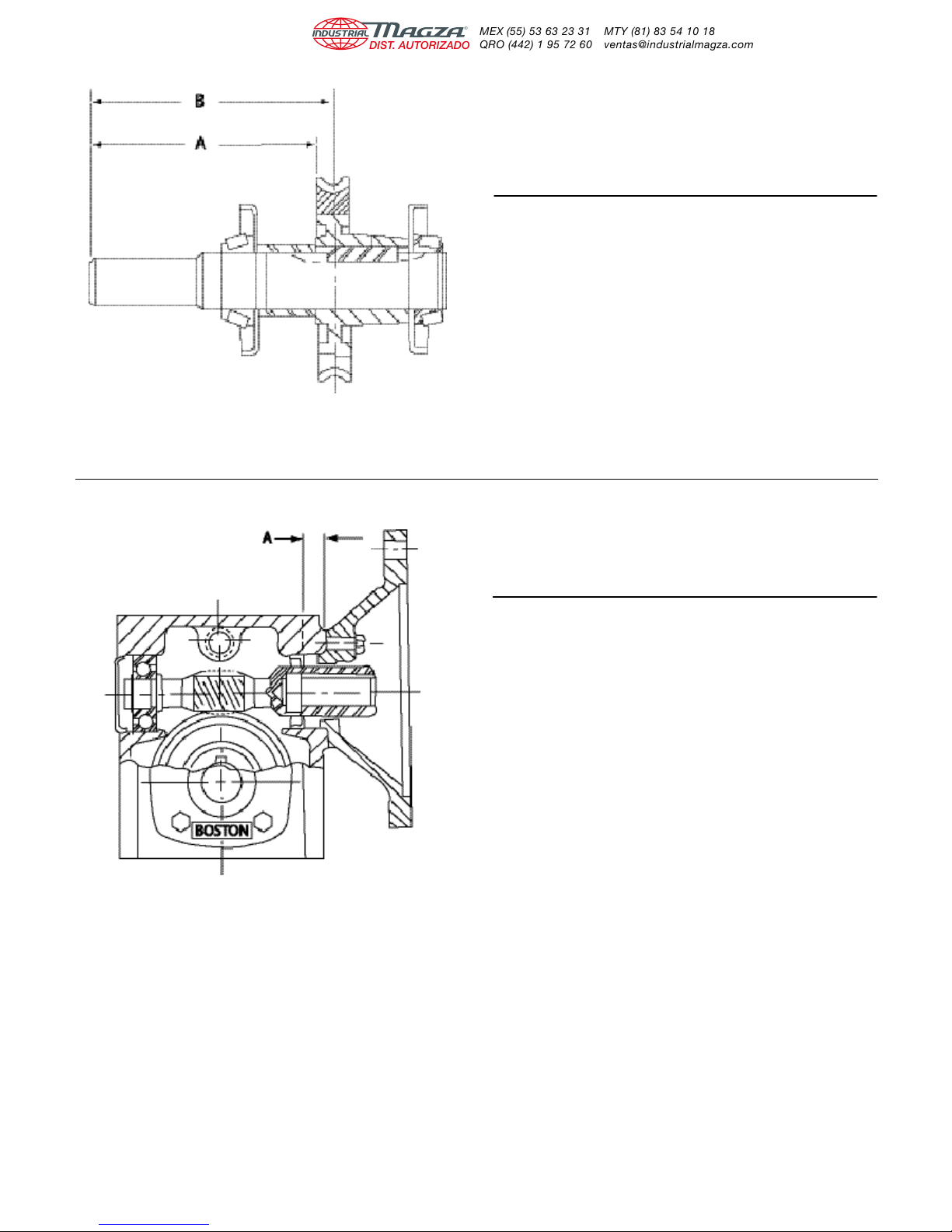
Unit “A” ± 1/64 “B” Ref. Only
730 6.310 6-3/4
732 7.469 7-1/16
738 7.25 7-3/4
752 8.44 9-1/16
760 9.28 10
Figure No. 1
Unit “A”
Size Dimension
F710/FW713 5/16
FW718
F713/FW721 3/8
FW726
F715 3/8
F718/FW732 3/8
F721/FW738 3/8
F724 3/8
F726 3/8
F730 3/8
F732 5/8
F738 5/8
NOTE: “A” Dimensions shown are original oil seal locations.
When seal is replaced add or subtract 1/16 to dimension
shown. This will allow seal to wear on a new surface for
extended life.
Figure No. 2
Doc. No. 57746 • Boston Gear® 700 Series Worm Gear Speed Reducers 14
Page 16
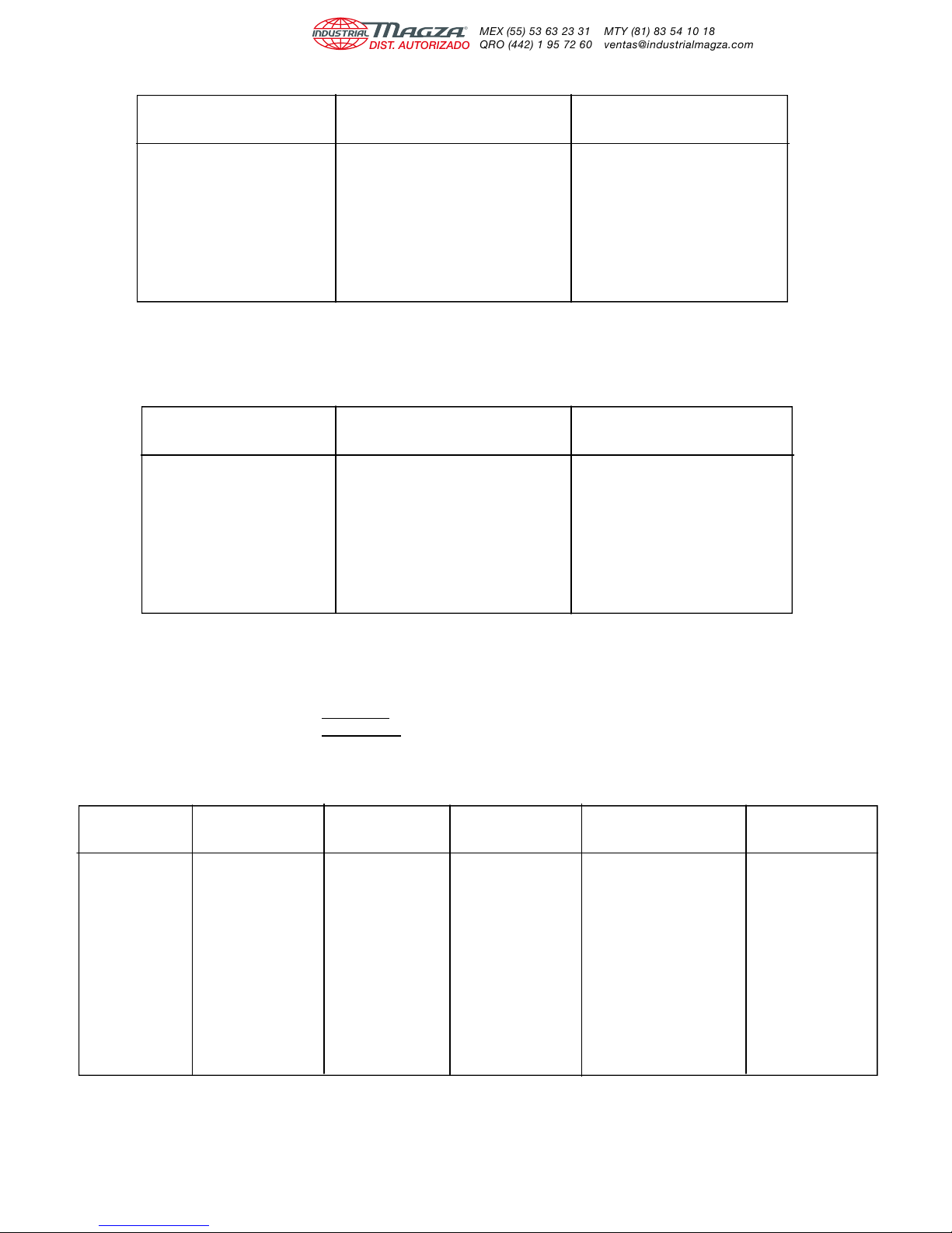
ENDPLAY - FLANGED REDUCTOR
INPUT SHAFT OUTPUT SHAFT
UNIT SIZE ENDPLAY ENDPLAY
F710, F713 Free Running Free Running
To .0075 Max. To .003 Max.
F715 Through Free Running Free Running
F730 To .009 Max. To .003 Max.
F732 Through Free Running Free Running
F738 To .003 Max. To .003 Max.
Figure No. 3
ENDPLAY - REDUCTOR & RF/QC TYPE
INPUT SHAFT OUTPUT SHAFT
UNIT SIZE ENDPLAY ENDPLAY
710, 713 Free Running Free Running
To .002 Max. To .003 Max.
715 Through Free Running Free Running
730 To .003 Max. To .003 Max.
732 Through Free Running Free Running
738 To .005 Max. To .003 Max.
Figure No. 4
Note: Endplays adjusted by -
1. Input Shaft - Adding or subtracting metal shims (Item 18)
2. Output Shaft - Adding or subtracting metal shims (Item 12)
SCREW TIGHTENING TORQUES (IN-LBS.)
UNIT CARRIER FLANGE FAN GUARD FAN ATTACH. PIPE
SIZE SCREW SCREW SCREW SCREW PLUG
F710 40-65 45-65 90
F713 132-156 132-156 132
F715 264-312 264-312 132
F718 264-312 264-312 132
F721 264-312 264-312 132
F724 264-312 264-312 132
F726 264-312 264-312 132
F730 264-312 264-312 132
F732 264-312 264-312 85-105 140-160 240
F738 480-552 264-312 85-105 140-160 240
F752 840-948 840-948 132-156 140-160 240
F760 1200-1368 840-948 132-156 140-160 240
15 Doc. No. 57746 • Boston Gear® 700 Series Worm Gear Speed Reducers
Figure No. 5
Page 17
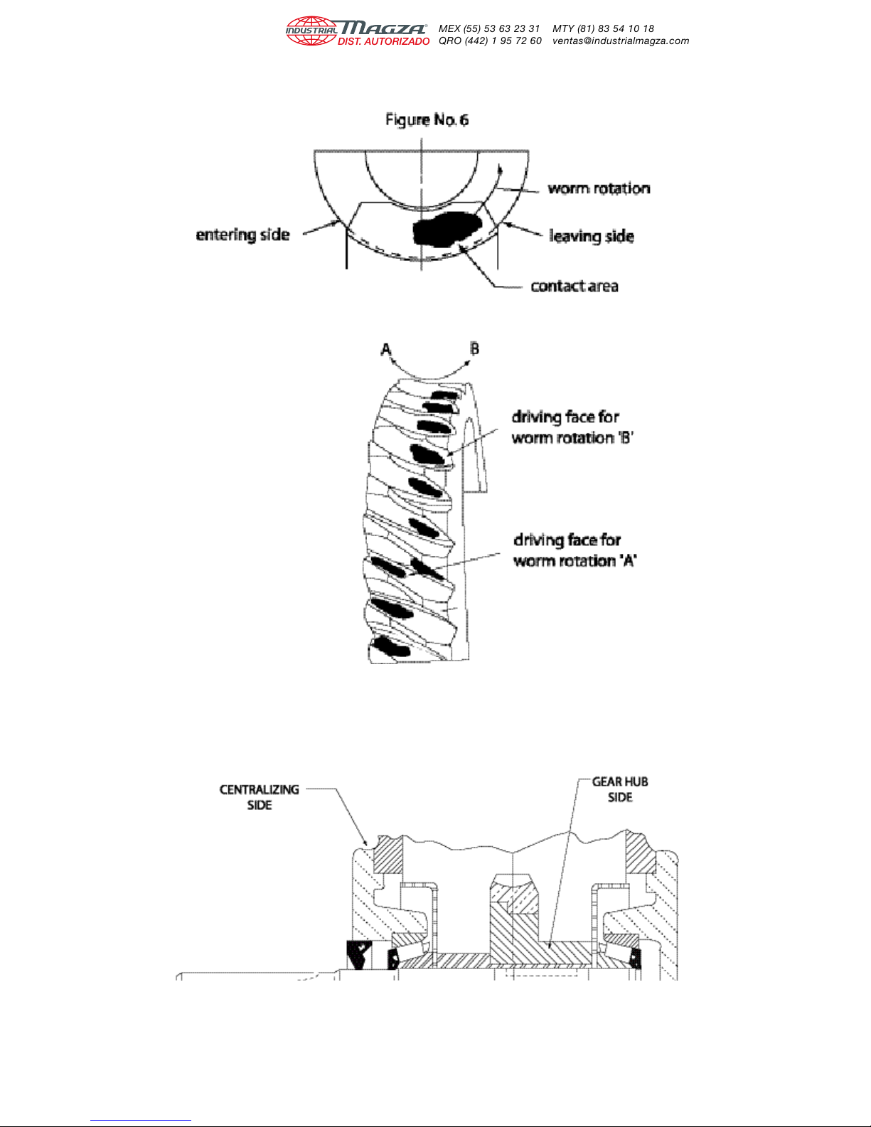
IDEAL POSITIONING OF WORM GEAR CONTACT
IDEAL POSITIONING OF WORM GEAR CONTACT
Doc. No. 57746 • Boston Gear® 700 Series Worm Gear Speed Reducers 16
Page 18
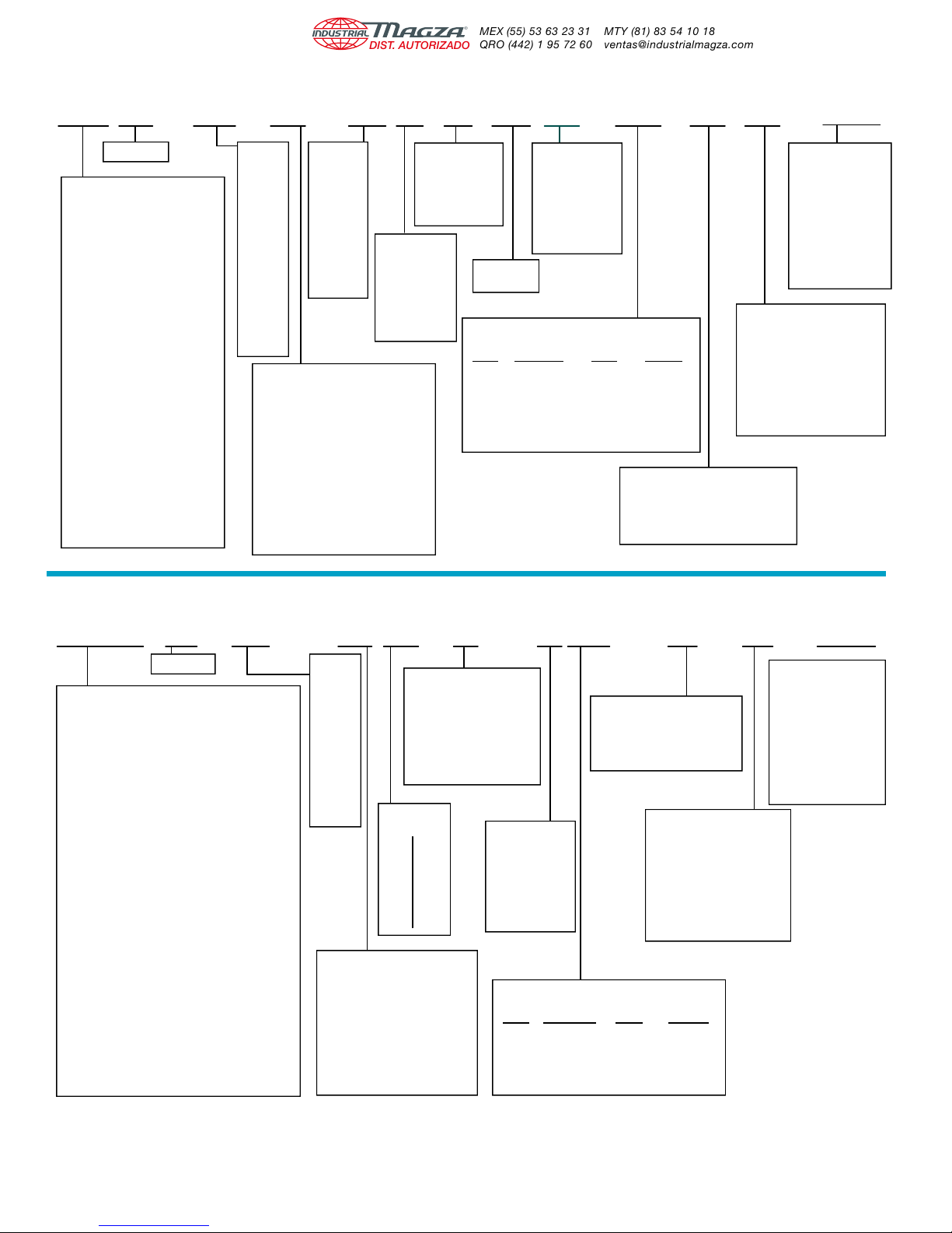
700 Series SingleReduction CatalogNumber Explanation
HQC 7 32 R - 30 A F P T - B7 H 3 - P20
700 SERIES
Blank - Projecting I/P & O/P shafts
HQC - Flanged reducer (Coupling
SSF* - Stainless flanged reducer
SSF* - Stainless flanged reducer
C Prefix- Cast iron flange and base
(*SSF/SSHF sizes 7/8, 721, 726 only)
STYLE
(No flange)
H - Projecting I/P, BostMount
hollow O/P shaft, (No flange)
S - Projecting I/P, hollow O/P
shaft (No flange)
F - Flanged reducer (Quill type),
projecting O/P shaft
HF - Flanged reducer (Quill type),
BostMount
hollow O/P shaft
SF - Flanged reducer (Quill type),
hollow O/P shaft
QC - Flanged reducer (Coupling
type), projecting O/P shaft
type), BostMount hollow
O/P shaft
(Quill type) projecting O/P
shaft
(Quill type) projecting O/P
shaft
CENTER
DISTANCE
(inches)
10 - 1.00
13 - 1.33
15 - 1.54
18 - 1.75
21 - 2.06
24 - 2.38
26 - 2.62
30 - 3.00
32 - 3.25
38 - 3.75
52 - 5.16
60 - 6.00
Blank - No base kit required
REDUCTION
RATIO TO 1
5
10
15
20
25
30
40
50
60
BASE
A - Horizontal base – Worm under
B - Horizontal base – Worm over
C - Vertical High base – I/P right
D - Vertical Low base – I/P right
E - Vertical High base – I/P left
F - Vertical Low base – I/P left
R/L - BostMount Output Bracket
X - Input Vertical Up
Y - Input Vertical Down
V - Hollow O/P with base – I/P right
W - Hollow O/P with base – I/P left
LUBRICATION
Blank - No Lube
S - Mobil SHC634
Factory Filled With
(732-760 sizes
L - Other than
standard
A -POSIVENT
Mobil SHC634
FAN
only)
Blank - No fan
F - Fan kit
P-Pressure
Relief
BORE NEMA INPUT
CODE MOUNTING BORE KEYWAY
B4 42CZ .500" 1/8 x 1/16
B5 56C .625 3/16 x 3/32
B7 140TC/180C .875 3/16 x 3/32
B9 180TC/210C 1.125 1/4 x 1/8
B11 210TC/250UC 1.375 5/16 x 5/32
B13 250TC 1.625 3/8 x 3/16
OIL SEAL
T – Indicates two
input seals.
V – Three piece
input sealing
system
P – Pressure
relief vent
NEMA MOUNTING
G - O/P Projection – Left
H - Double O/P Projection
J - O/P Projection – Right
700 Series Double Reduction Catalog Number Explanation
Blank -No Lubrication Supplied
1 -Standard Mounting
2-6 -Refer to Mounting
OUTPUT SHAFT ASSEMBLY
(When facing Input)
H SERIES OUTPUT
BORE CODE
For H700 Series only.
Specified in 1/16"
increments. See
Worm Gear Drives
Catalog for
complete offering.
Example:
1 1/4" = P20
MOUNTING POSITIONS
For Factory Prelubrication
Indicate Mounting Position
Positions in Catalog
HQCWA 7 32 R 100 A T B5 - H 3 - P20
700 SERIES
STYLE
WA - Parallel shafts, projecting I/P & O/P
HWA - Parallel shafts, projecting I/P, BostMount
Hollow O/P
SWA - Parallel shafts, projecting I/P, hollow O/P
WC - Right Angle shafts, projecting I/P & O/P
HWC - Right Angle shafts, projecting input,
BostMount hollow output shaft.
SWC - Right Angle shafts, projecting I/P, hollow O/P
FWA - Parallel shafts, Quill type I/P, projecting O/P
HFWA - Parallel shafts, Quill type I/P, BostMount
Hollow O/P
SFWA - Parallel shafts, Quill type I/P, hollow O/P
FWC - Right Angle shafts Quill type I/P,
projecting O/P
HFWC - Right Angle shafts, Quill type input,
BostMount hollow output shaft
SFWC - Right Angle shafts, Quill type I/P, hollow O/P
QCWA - Parallel shafts, Coupling type I/P,
projecting O/P
HQCWA - Parallel shafts, Coupling type I/P,
BostMount hollow O/P
QCWC - Right Angle shafts, Coupling type I/P,
projecting O/P
HQCWC - Right Angle shafts, Coupling type input,
BostMount hollow output shaft
C Prefix - Cast iron flange and base
CENTER
DISTANCE
(inches)
13 - 1.33
18 - 1.75
21 - 2.06
26 - 2.62
30 - 3.00
32 - 3.25
38 - 3.75
52 - 5.16
60 - 6.00
REDUCTION
RATIO TO1
100 1200
150 1800
200 2000
300 2400
400 3000
600 3600
900
Blank - No base kit required
BASE
A & B - Horizontal bases
C & E - Vertical High bases
D & F - Vertical Low bases
R/L - BostMount Output Bracket
X - Input Vertical Up
Y - Input Vertical Down
V/W - Hollow O/P with base
LUBRICATION
Blank - No Lube
S - Mobil SHC634
A - PosiVent
(Factory Filled
With Mobil
SHC634)
T – Indicates two
V – Three piece
OUTPUT SHAFT ASSEMBLY
(When facing Input)
G - O/P Projection – Left
H - Double O/P Projection
J - O/P Projection – Right
OIL SEAL
input seals.
input sealing
system
P – Pressure
relief vent
MOUNTING POSITIONS
Blank - No Lubrication Supplied
For Factory Prelubrication
Indicate Mounting Position
1 - Standard Mounting
2 - 6 - Refer to Mounting
Positions in Catalog
NEMA MOUNTING
BORE NEMA INPUT
CODE MOUNTING BORE KEYWAY
B4 42CZ .500" 1/8 x 1/16
B5 56C .625 3/16 x 3/32
B7 140TC/180C .875 3/16 x 3/32
B9 180TC/210C 1.125 1/4 x 1/8
H SERIES OUTPUT
BORE CODE*
For H700 Series only.
Specified in 1/16"
increments See
Worm Gear Drives
Catalog for
complete offering.
Example:
1 1/4" - P20
*H Series Only
NOTE: Contact factory for other model numbers.
17 Doc. No. 57746 • Boston Gear® 700 Series Worm Gear Speed Reducers
Page 19
700 SERIES WARRANTY
The Company warrants that all 700 Series speed reducers will be free from defects in material and workmanship over
the lifetime of the product.
Oil seals are considered to be replaceable maintenance items.
Any products which shall be proved to the Company’s satisfaction to have been defective at the time of delivery in these
respects will be replaced or repaired by the Company at its option. Freight is the responsibility of the customer. The
Company’s liability under this warranty is limited to such replacement or repair and it shall not be held liable in any form of
action for direct or consequential damages to property or person. THE FOREGOING WARRANTY IS EXPRESSLY MADE
IN LIEU OF ALL OTHER WARRANTIES WHATSOEVER, EXPRESS, IMPLIED AND STATUTORY AND INCLUDING
WITHOUT LIMITATION THE IMPLIED WARRANTIES OF MERCHANTABILITY AND FITNESS.
No employee, agent, distributor, or other person is authorized to give additional warranties on behalf of Boston Gear, nor
to assume for Boston Gear any other liability in connection with any of its products, except an officer of Boston Gear by a
signed writing.
Boston Gear
14 Hayward Street
Quincy, MA 02171
tel 617.328.3300
fax 617.479.6238
www.bostongear.com
 Loading...