

Boston Acoustics DXB User's Manual
DXB
NEW CONSTRUCTION BRACKET
for DX Pro Designer Series Speaker
INSTALLATION INSTRUCTIONS
The DXB New Construction Bracket is a mounting frame for the DX Pro in-wall speaker system. The
bracket attaches to exposed studs or beams and provides a guide for the wall board installer. It can be
used for installation in ceilings and walls. This package contains two complete bracket assemblies:
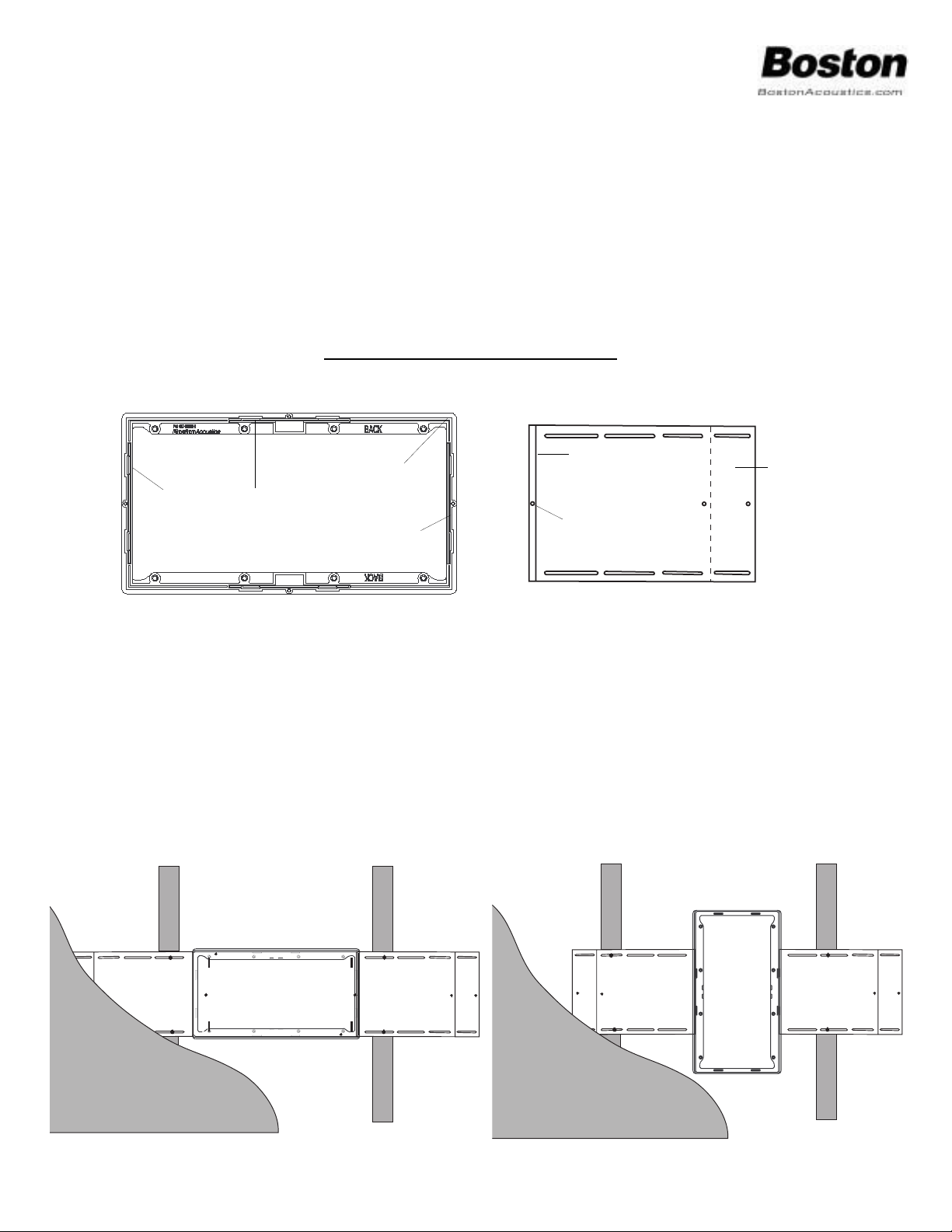
DXB Bracket Frame (A) - rear view
Bracket Wing (B)
New Construction Installation (Wall or Ceiling Mount):
1. Determine mounting orientation (horizontal or vertical)
2. Attach the Bracket Wings (B) to the Bracket Frame (A) by firmly inserting Locking Tab (D) of each wing
into the Mounting Channel (F) located on the rear of the Bracket Frame. The bracket and wing will snap
tightly together. However, if additional strength is required, a #8 x 3/8" screw (not supplied) may be
used. After snapping the bracket and wing together, insert the screw through the Locking Screw Hole (E)
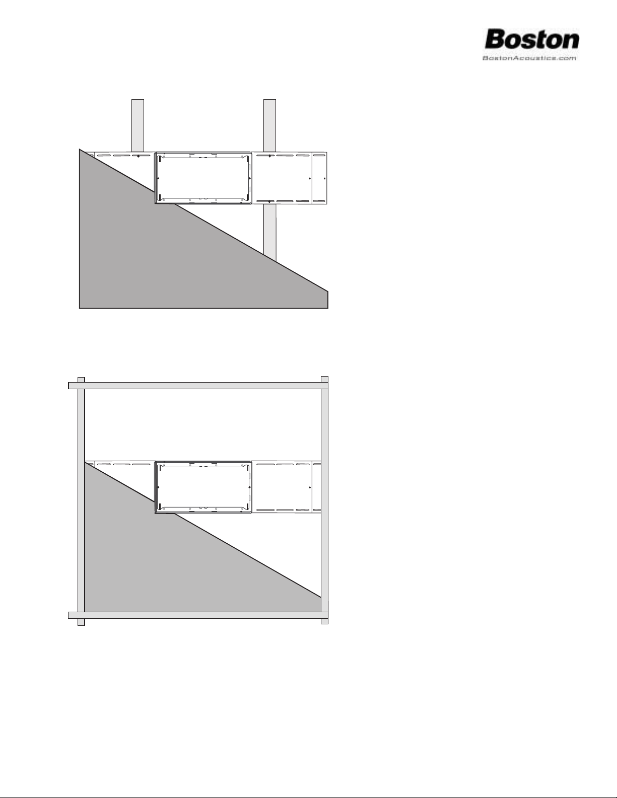
3. Attach the DXB bracket assemblies to studs or beams with nails or drywall screws.
4. Using a wire tie or electrical tape secure the speaker wire to the bracket at the Cable Tie Points (G) so that
it is not lost behind the ceiling or wall surface.
Horizontal Mounting
Vertical Mounting
Outer Flange (C)
Mounting Channel (F)
Cable Tie Points (G)
Locking Tab (D)
Locking Screw Hole (E)
Wing Extension (H)
Description Quantity
DXB bracket frame 2
Bracket wing 4
Suspended Ceiling Installation:
1. Remove ceiling tile at desired location.
2. Center Bracket Frame within 2’ dimension
on ceiling tile.
3. Using Outer Flange (C) as a template, trace
cutout hole. Cut tile so that Outer Flange fits
into cutout hole.
4. Attach Bracket Wings to DXB Bracket Frame
as previously described. Make certain that
Wing Extensions (H) remain intact.
5. Install Bracket above the ceiling tile so that
the weight of the assembly is supported by
the ceiling grid. Check local codes and ceiling specifications to determine whether
additional support is required.
6. Remove speaker grille (see page 7, #3 in DX
Pro manual)
7. Using the 8 supplied screws, attach the DX
Pro speaker to the DXB bracket. Do not
over tighten screws.
8. Replace grille.
Boston Acoustics, Inc.
300 Jubilee Drive
Peabody, MA 01960
www.bostonacoustics.com
978-538-5000
042-001068-0
5. Finished wall surfaces must align with Outer
Flange (C) as shown.
6. Remove speaker grille (see page 7, #3 in DX
Pro manual)
7. Using the 8 supplied screws, attach the DX
Pro speaker to the DXB bracket. Do not
over tighten screws.
8. Replace grille.
 Loading...