

Boston Acoustics CS 285, CS 275 User Manual
CS 275 • CS 285
8
7
/8"
226mm
11
13
/16"
300mm
14
13
/16"
351mm
need measurements and DSi #
7
3
/8"
187mm
10"
254mm
13
"
305mm
Classic In-Wall/In-Ceiling Speakers
Classic Montaje empotrado Sistemas de altavoces
Systèmes d’enceintes encastrées Classic
Einbau-Lautsprechersysteme
Specications
CS 275 CS 285
Frequency Response 65Hz-20kHz 50Hz-20kHz
Recommended Amplier Power 10 – 90 watts 10 – 100 watts
Sensitivity 1 watt (2.83v) at 1m 90dB 90dB
Nominal Impedance 8 ohms 8 ohms
Crossover Frequency 4,000Hz 5,000Hz
Woofer 6½” (165mm) 8” (203mm)
Tweeter ¾” (20mm) ¾” (20mm)
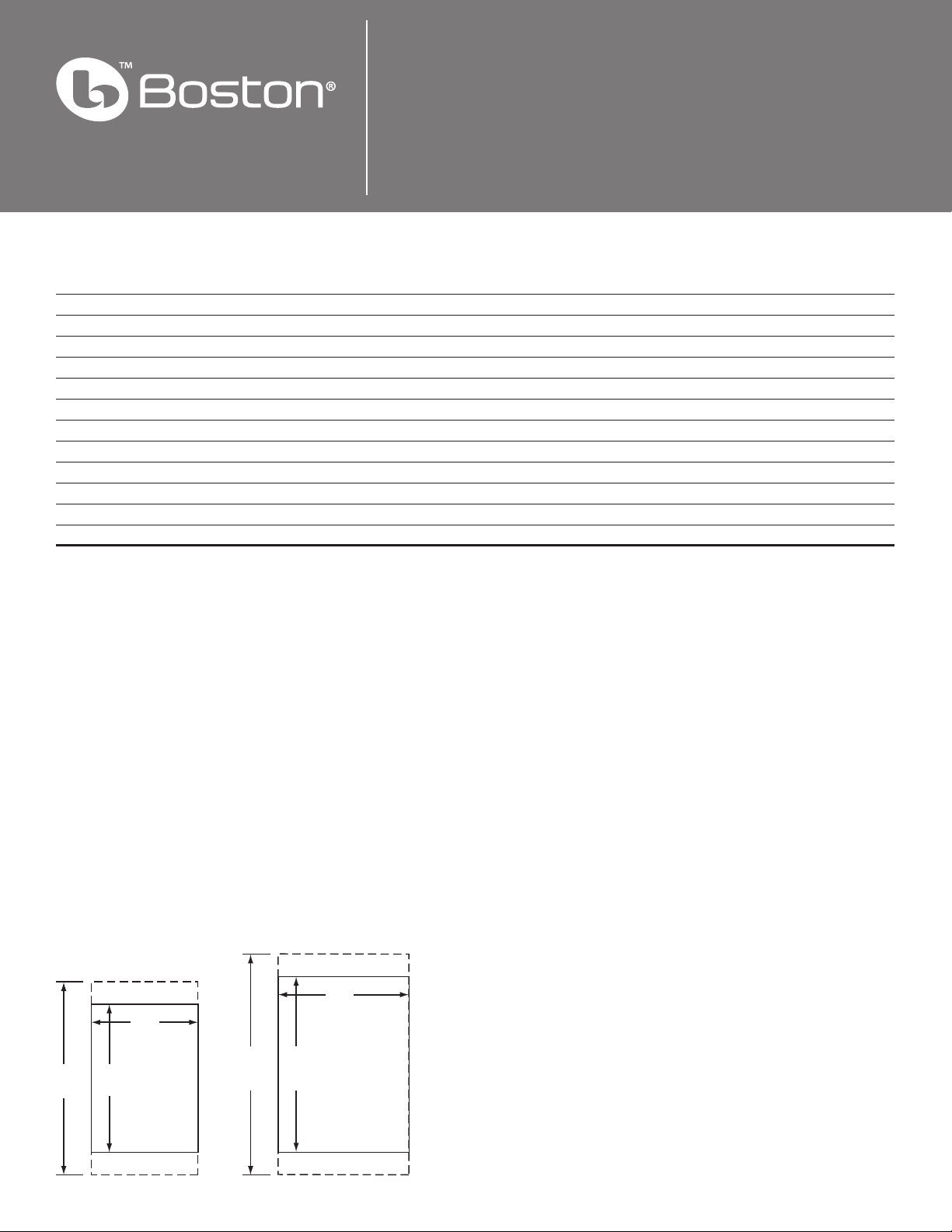
External Dimensions 11⁄ x 8⁄” (294x224mm) 13⁄ x 10⁄” (340x262mm)
Mounting Hole Cutout 10 x 7⁄” (254x187mm) 11⁄ x 8⁄” (300x226mm)
Mounting depth (from surface) 3” (75mm) 3⁄”(110mm)
Optional New Construction Bracket NCB6 NCB8
Optional Cover Plate Cover6 Cover8
Required Clearances
Behind the mounting surface,
there must be 1½-inch (38mm)
clearance around the mounting
hole.
Optional Brackets for
New Construction
For new construction installations, we oer new construction
brackets. The NCB brackets act as
a perfect guide when cutting the
wallboard.
Model Bracket
CS 275 NCB6
CS 285 NCB8
To Remove Grille
If you need to remove the grille,
gently lift it out at the edges. Use
a sharp pointed instrument such
as an awl.
Espacios libres necesarios
Detrás de la supercie de montaje debe haber 38mm libres alrededor del espacio del montaje.
Soportes opcionales para
construcción nueva
Para instalaciones en
construcciones nuevas ofrecemos
soportes opcionales. Los soportes
NCB sirven perfectamente de
guías para el corte
de cartón-yeso.
Modelo Soporte
CS 275 NCB6
CS 285 NCB8
Para quitar la rejilla
Si necesita quitar la rejilla,
levántela con cuidado por
los extremos. Utilice una
herramienta alada y
puntiaguda, como un punzón.
CS 285CS 275
Dégagements nécessaires
Derrière la surface de montage,
un dégagement de 38mm doit
être présent autour du trou de
montage.
Supports de xation
facultatifs pour
constructions neuves
Pour les installations dans des
constructions neuves, nous
orons des supports spéciaux.
Ces supports sont idéaux pour
servir de guides lors de
la découpe des murs.
Modèle Support
CS 275 NCB6
CS 285 NCB8
Retrait de la grille
Pour retirer la grille, soulevez-la
délicatement en la tenant par
les bords. Utilisez un instrument
pointu alé, tel qu’un poinçon.
Erforderliche Mindestabstände
Hinter der Montageäche muss
um das Montageloch ein Spiel
von 38mm vorhanden sein.
Optionale Halterungen für
Neubauten
Für die Montage in neuen
Gebäuden bieten wir besondere
Halterungen. Die NCB-Halterungen sind eine ideale Richtlinie, wenn Gipskartonplatten
geschnitten werden.
Modell Halterung
CS 275 NCB6
CS 285 NCB8
Entfernen des Ziergitters
Wenn das Ziergitter entfernt
werden muss, heben Sie dieses
an den Kanten vorsichtig heraus.
Verwenden Sie dazu ein spitzes
Werkzeug wie eine Ah
Prior to Installation
Antes del montaje
Avant l’installation
Vor der Installation
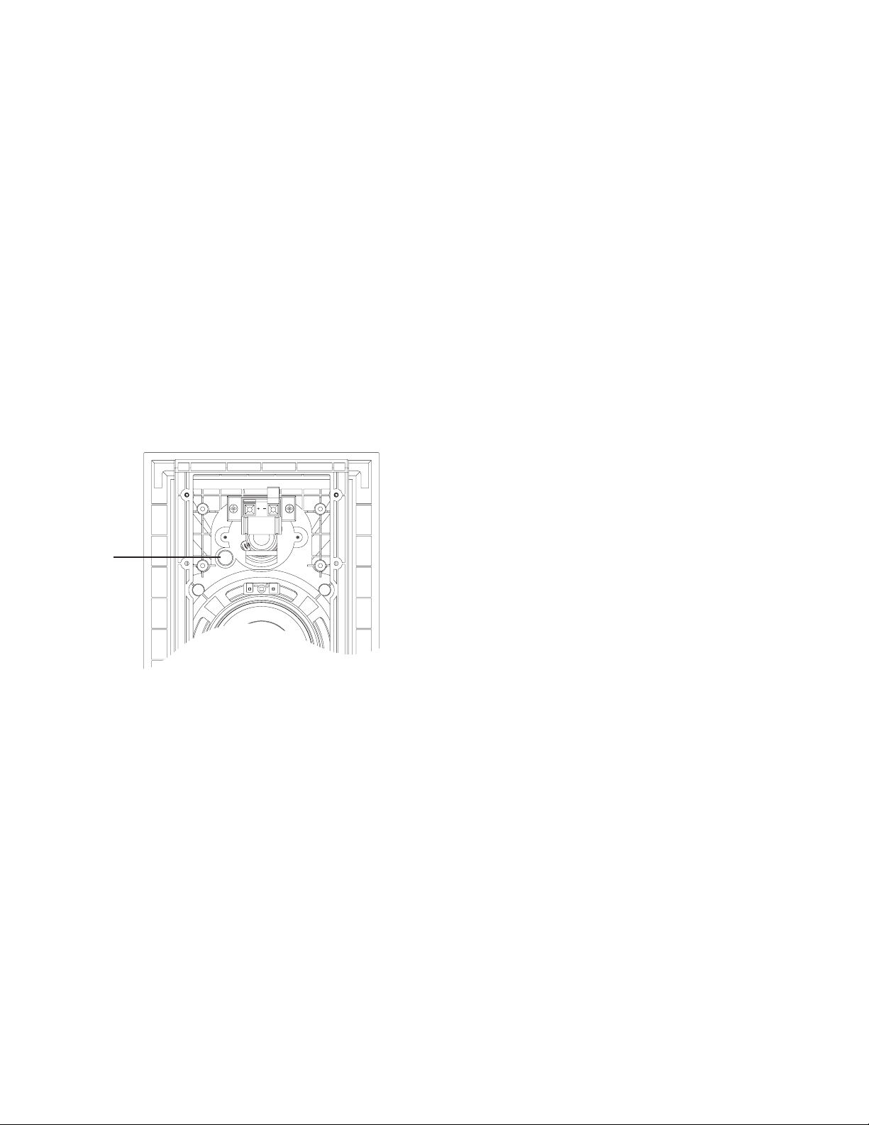
IR Sensor Knockout
Each speaker has a knockout
molded into the speaker bae
that will accommodate standard
½-inch diameter infrared
(IR) sensors.
To use this feature:
1. Lay the speaker face down
on corrugated cardboard.
The packing material may
be used.
2. Use a #2 Phillips screwdriver
and hammer to punch out
the knockout from behind.
3. Install the IR sensor.
CAUTION: IR sensor range
and operating angle will be
reduced by the speaker grille
and cloth. IR sensor will work
best on-axis to the face of the
speaker. Test before installing.
Instalación de sensores IR
Cada altavoz cuenta con un
sitio estampado en la carcasa
para alojar sensores estándar
infrarrojos de 12.7mm de
diámetro.
Para utilizar esta característica:
1. Ponga el altavoz boca abajo
en un cartón rugoso. Puede
servir el material de embalaje.
2. Utilice un destornillador de
estrella o cruz y un martillo
para perforar el agujero
ciego por detrás.
3. Instale el sensor IR.
PRECAUCIÓN: El alcance y
ángulo de funcionamiento del
sensor IR se verán reducidos
por la rejilla y la pantalla difusora
del altavoz. El sensor IR
funcionará mejor si se lo instala
derecho con respecto a la
parte frontal del altavoz.
Pruébelo antes de proceder a
la instalación.
Pièce éjectable pour
capteur infrarouge
Chaque enceinte comporte
une pièce éjectable moulée
dans le haut-parleur à membrane,
dont le retrait permet de
loger un capteur infrarouge standard
d’un diamètre de 12.7mm.
Pour utiliser cette fonction :
1. Couchez l’enceinte face vers le
bas sur du carton ondulé
(vous pouvez utiliser son
carton d’emballage).
2. Avec un tournevis cruciforme
et un marteau, éjectez la
pièce par l’arrière.
3. Installez le capteur infrarouge.
ATTENTION : la grille et le diuseur
de l’enceinte réduisent
la portée et l’angle de fonctionnement
du capteur IR. Pour
une performance optimale,
placez le capteur IR dans l’axe
de l’enceinte. Testez avant
d’installer.
Aussparung für den IR-Sensor
Jeder Lautsprecher verfügt über
eine vorgeformte Aussparung in
der Lautsprecher-Schallwand, die
standardmäßige Infrarotsensoren
(IR-Sensoren) mit 12.7mm
Durchmesser aufnehmen.
Zur Nutzung dieser Funktion:
1. Legen Sie den Lautsprecher
mit der Vorderseite nach
unten auf ein Stück
Wellpappe. Dazu kann das
Verpackungsmaterial
verwendet werden.
2. Schlagen Sie mit einem
Kreuz-schlitz- Schraubendreher
und einem Hammer die
Aussparung von der
Rückseite her heraus.
3. Montieren Sie den IRSensor.
VORSICHT: Reichweite und
Betriebsfeld des IR-Sensors
werden durch das Ziergitter
und den Scrim reduziert. Der
IR-Sensor funktioniert auf der
Achse zur Stirnseite des
Lautsprechers am besten. Die
Funktionsweise sollte vor der
Installation überprüft werden.
IR sensor
Installation Instructions
WARNING
Always turn o the amplier or receiver
when connecting speakers or any other
components to the system.
NOTE
This manual assumes the installer
possesses skill in the proper use of hand
and power tools, knowledge of local
building and re codes, and a familiarity
with the environment behind the wall
or ceiling in which the speakers will
be installed.
Tools You’ll Need
1. A utility knife, jig saw, or other tool
for cutting the required hole in the
mounting surface.
2. A #2 Phillips screwdriver.
3. A wire cutter or stripper for
preparing the speaker wires.
4. A pencil.
Instrucciones de montaje
AVISO
Apague siempre el amplicador o el receptor
al conectar altavoces o cualquier otro componente al sistema.
NOTA
En este manual se presupone que el instalador
posee habilidad en el manejo de herramientas
manuales y eléctricas, conocimiento sobre los
códigos vigentes de construcción local y normas sobre incendios y que está familiarizado
con el entorno tras el muro o techo en los que
se instalarán los altavoces.
Herramientas necesarias
1. Una navaja multiusos, una sierra
caladora u otra herramienta para cortar
el agujero adecuado en la supercie de
montaje.
2. Un destornillador de estrella o cruz del
número 2.
3. Un cortador de alambre o un
pelacables para preparar el
cableado de los altavoces.
4. Un lápiz.
Instructions d’installation
AVERTISSEMENT
Débranchez toujours l’amplicateur ou le
récepteur avant de connecter les enceintes ou
tout autre composant du système.
REMARQUE
Ce manuel suppose que l’installateur
sait utiliser les outils à main et à moteur
nécessaires à l’installation, qu’il connaît la
réglementation en vigueur sur la construction et l’incendie, et qu’il sait exactement ce
qui se trouve derrière les murs ou les plafonds
sur lesquels les enceintes seront installées.
Outils nécessaires
1. Un couteau, une scie à découper ou
tout autre outil capable de découper
l’orice nécessaire dans la surface de
montage.
2. Un tournevis cruciforme No. 2.
3. Une pince coupante ou à dénuder
pour préparer les ls des enceintes.
4. Un crayon noir
Installationsan-weisungen
ACHTUNG
Den Verstärker oder Empfänger immer
abstellen, wenn Lautsprecher oder andere
Komponenten an das System angeschlossen
werden.
HINWEIS
Dieses Handbuch setzt voraus, dass der Installateur im Umgang mit Hand- und Elektrowerkzeugen versiert ist, die örtlichen Bau- und
Brandschutzvorschriften kennt und weiß, wo
und welche Leitungen in der Wand bzw. hinter
der Wandverkleidung verlaufen, in der die
Lautsprecher montiert werden sollen.
Benötigte Werkzeuge
1. Ein Exaktormesser, eine Stichsäge oder
anderes Werkzeug zum Ausschneiden
des notwendigen Lochs aus
der Montageäche.
2. Einen Kreuzschlitz-Schraubendreher,
Größe 2.
3. Eine Drahtzange oder einen
Drahtstripper zur Vorbereitung der
Lautsprecherkabel.
4. Einen Bleistift.
 Loading...