

Boston GT-20, GT-22 Owner's Manual
os
ton
T-20
T-22
2-Channel, High-Current/High-Power Amplifiers
Boston
Boston
Acoustics
Table
of
Contents
Parts
Lis
Features and Specifications
Control Functions
Control
functions
(cont.)
Mechanical Functions
Recessed RCA
inputs
Control
cover
removal & reinstallation
Multi-position
mounting
feet
Vents (side & rear)
Mechanical
functions
(cont.)
Amplifier
linking
Wire
connection
Fuses
General Installation Precautions
Before
you
install
Battery
&
charging
system
Wire
routing
Installation-Amplifier
Mounting
Choose
the
mounting
location
Height,
width,
and
depth
diagrams
Installation-amplifier
mounting
(cont.)
Passenger
&
trunk
compartment
mounting
Installation-Fuses & Wiring
Amplifier
fuses
Wire
gauge
Installation-fuses&wiring
(cont.)
Power/B+&power/ground
(GND)
connection
Remote
input
connection
Speaker
output
connection
Installation-fuses&wiring
(cont.)
Mono
subwoofer
operation
Setup Tuning-Full-range Speakers
Music
Sensitivity
controls
Highpass &lowpass crossover controls
Setup
tuning-full-range
speakers (cont.)
Head
unit
Volume
Input
sensitivity
control
Crossover
controls
Setup
tuning-full-range
speakers (cont.)
"Q"
control
Setup
Tuning-Rear
Fill Speakers
Setup
Tuning-Subwoofers
Input
switch
Setup
tuning-subwoofers
(cont.)
Head
unit
Volume
Input
sensitivity
control
Lowpass crossover
control
Phase
System Examples
Amplifier Troubleshooting Guide
Contact and Warranty Information
2
3
3
4
5
6
6
6
6
6
7
7
7
7
8
8
8
8
9
9
9
10
10
10
10
10
11
11
11
11
12
12
12
12
12
12
13
13
13
13
13
14
14
14
14
14
15
15
15
15
15
15
16,17
18
19
Parts List
Included Hardvvare: GT-20 >-22
(1)
owner's manual
(1)
female
quick-connect
terminal
(1)
2mm
hex
wrench (for
speaker
input)
(1)
3mm
hex
wrench (for
power
input)
(4)
mounting
screws
Features and Specifications
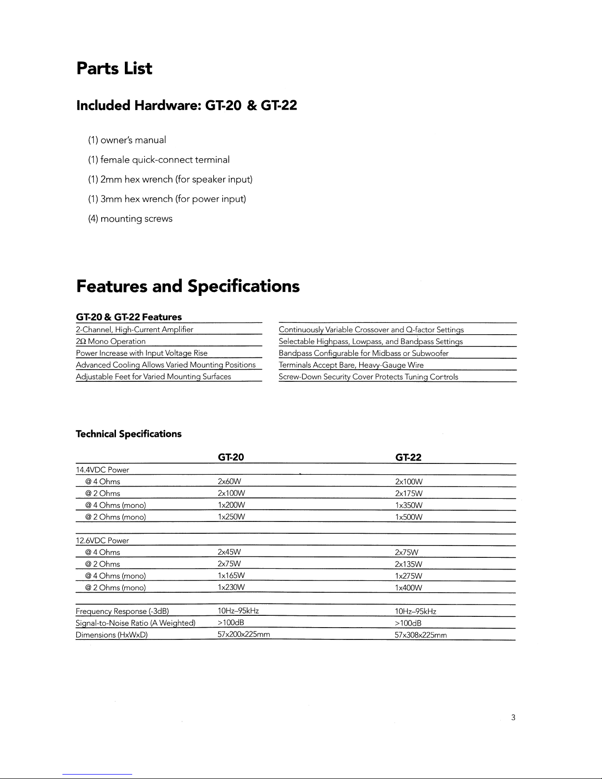
GT-20 & GT-22 Features
2-Channel, High-Current
Amplifier
212
Mono
Operation
Power Increase with Input Voltage
Rise
Advanced Cooling Allows Varied
Mounting
Positions
Adjustable Feet
for
Varied
Mounting
Surfaces
Continuously Variable Crossover and
Q-~actor
Settings
Selectable Highpass, Lowpass, and Bandpass Settings
Bandpass Configurable
for
MidbassorSubwoofer
Terminals
Accept
Bare, Heavy-Gauge Wire
Screw-Down Security Cover Protects Tuning Controls
Technical Specifications
GT-20
GT-22
14.4VDC Power
@40hms
2x60W
2x100W
@20hms
2x100W
2x175W
@4 Ohms (mono) 1x200W
1x350W
@2Ohms (mono)
1x250W
1x500W
12.6VDC Power
@40hms
2x45W
2x75W
@20hms
2x75W
2x135W
@4 Ohms (mono)
1x165W
1x275W
@2Ohms (mono)
1x230W
1x400W
Freguency Response (-3dB)
10Hz-95kHz
10Hz-95kHz
Signal-to-Noise Ratio (A Weighted)
>100dB
>100dB
Dimensions (HxWxD)
57x200x225mm
57
x308x225mm
3
Control Functions
............
···········11··························:········11······
··············D···..·
11
:,,:1
1
III
~=.=
........
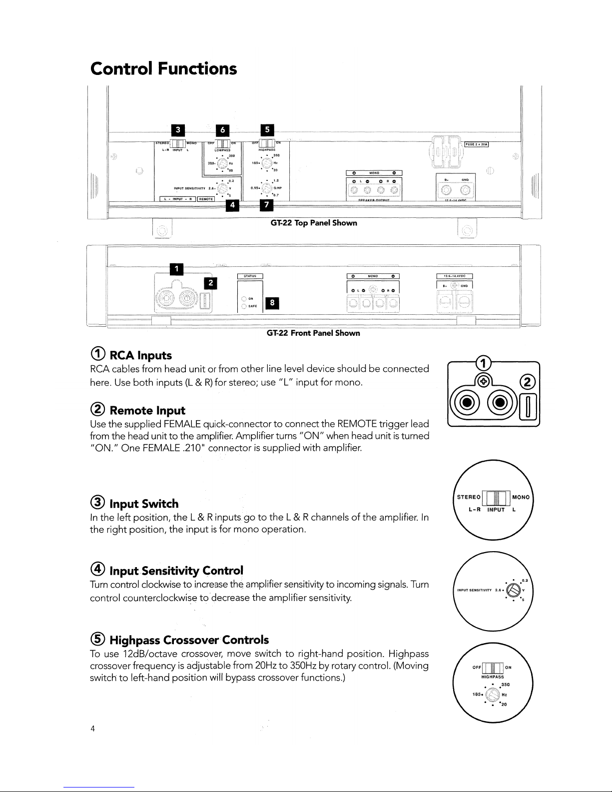
GT-22 Top Panel Shown
<D
RCA Inputs
RCA cables
from
head
unitorfrom
other
line level device shouldbeconnected
here. Use
both
inputs
(L&R)
for
stereo; use
"L"
input
for
mono.
® Remote Input
Use
the
supplied FEMALE quick-connectortoconnect
the
REMOTE
trigger
lead
from
the
head unittothe
amplifier~
Amplifierturns
"ON"
when head unitisturned
"ON."
One
FEMALE .210"
connectorissupplied
with amplifier.
® Input Switch
In
the
left
position,
the
L & R
inputsgoto
the
L & Rchannelsofthe
amplifier.
In
the
right
position,
the
inputisfor
mono
operation.
@ InputSensitivity Control
Turn control clockwisetoincreasethe amplifiersensitivitytoincoming signals. Turn
control
counterclockwi~e
to'decrease
the
amplifier sensitivity.
® Highpass Crossover Controls
To
use 12dB/octave crossover,
move
switchtoright-hand position. Highpass
crossover
frequencyisadjustable from 20Hzto350Hzbyrotary control. (Moving
switchtoleft-hand
position
will bypass crossover functions.)
4
Control Functions (cont.)
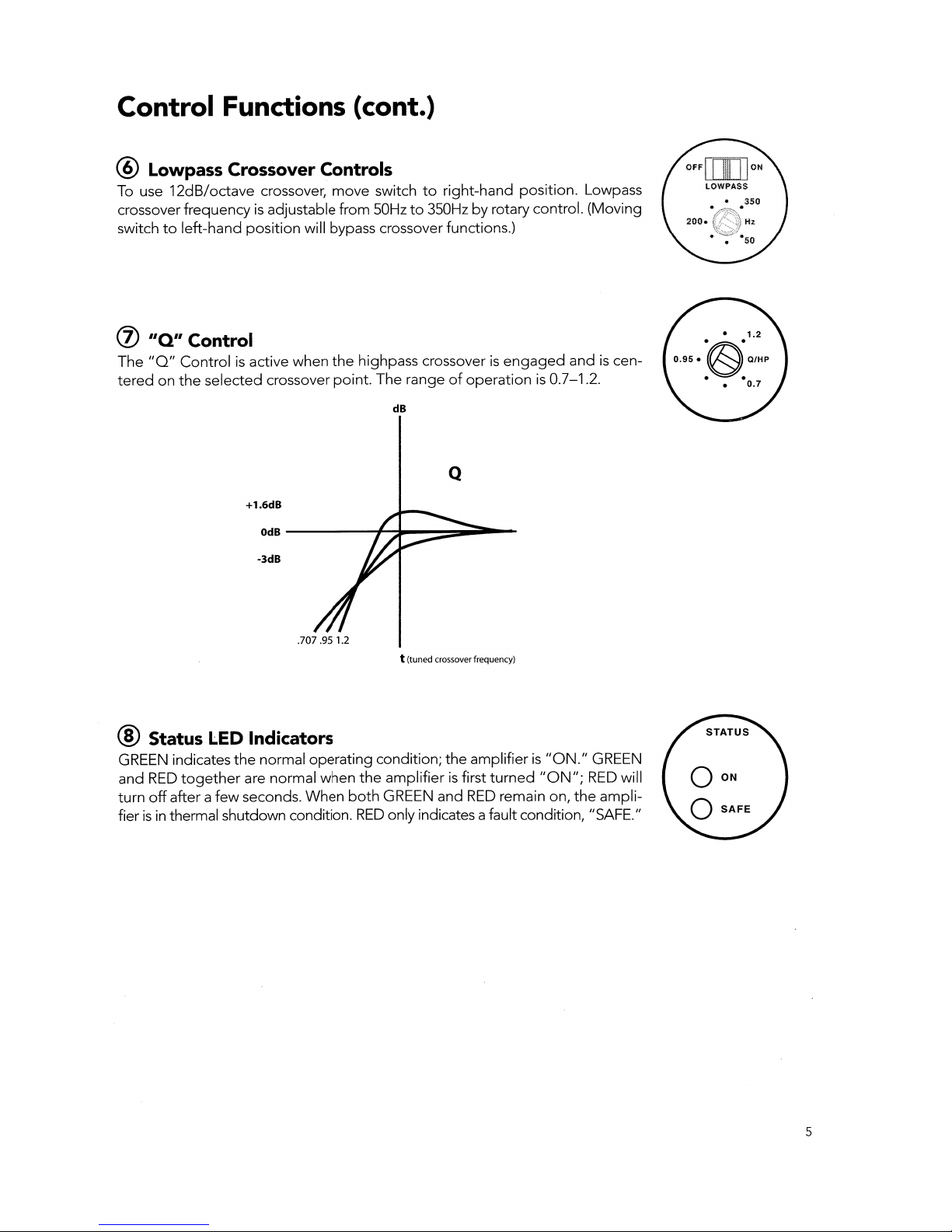
@ Lowpass Crossover Controls
To use
12dB/octave
crossover/
move
switchtoright-hand
position.
Lowpass
crossover
frequencyisadjustable
from
50Hzto350Hzbyrotary control.
(Moving
switchtoleft-hand
position
will bypass crossover functions.)
(j)
"Q"
Control
The
IIQII
Controlisactive
when
the
highpass crossoverisengaged
andiscen-
teredonthe
selected
crossover
point.
The
rangeofoperationis0.7-1.2.
dB
Q
+1.6dB
OdB
-----.,.....~-~~
...
--
-3dB
.707 .95 1.2
t (tuned crossoverfrequency)
® Status LED Indicators
GREEN
indicates
the
normal
operating
condition;
the
amplifier
is
1I0N.1I
GREEN
and
RED
together
are
normal
when
the
amplifierisfirst
turned
1I0NII;
RED
will
turn
off
afterafew
seconds.
When
both
GREEN
and
RED
remain on/
the
ampli-
fierisin thermal shutdown condition.
RED
only indicates a fault condition/
IISAFE.
II
5
Mechanical Functions
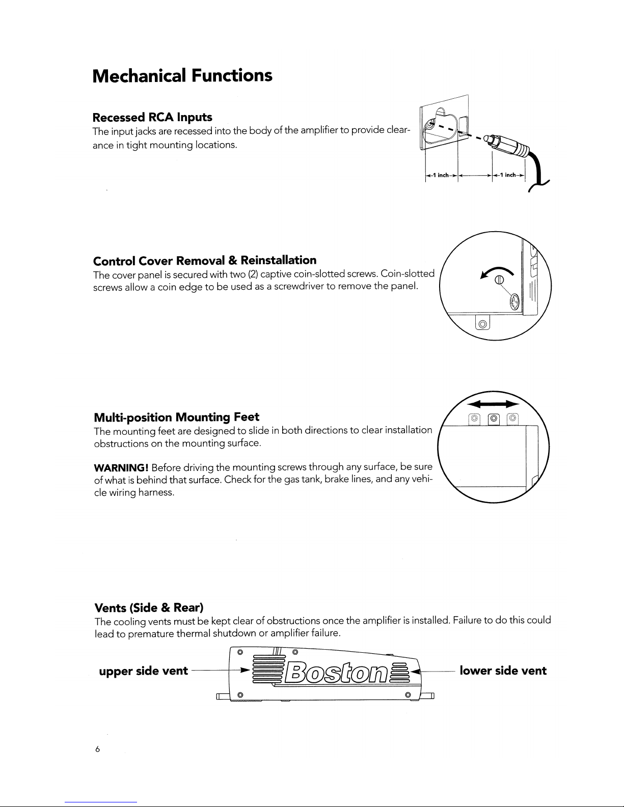
Recessed RCA Inputs
The
input
jacks are recessed
into
the
bodyofthe
amplifiertoprovide
clear-
ance in
tight
mounting
locations.
Control Cover Removal & Reinstallation
The
cover panelissecured with
two
(2)
captive coin-slotted screws.
Coin-slotted
screws
allow
a coin
edgetobe
usedasa screwdrivertoremove
the
panel.
Multi-position Mounting Feet
The
mounting
feet
are
designedtoslide in
both
directionstoclear installation
obstructionsonthe
mounting
surface.
WARNING! Before
driving
the
mounting
screws
through
any surface!besure
of
whatisbehind
that
surface. Check
for
the
gas tank! brake lines!
and
any vehi-
cle
wiring
harness.
Vents (Side & Rear)
The
cooling
vents
mustbekept
clearofobstructions once
the
amplifierisinstalled. Failuretodo
this
could
leadtopremature
thermal
shutdownoramplifier
failure.
upper side
vent
----f----l~
§§1l3@@[1@[JiJ
ii~--
lower side vent
6
 Loading...