

Page 1
DOC: BOS0481
D412 / D412+MC1 USE R MA NUA L
1 / 93
ENGLISH
Garage Equipment Associati on
Boston Garage Equipment, 199 New Road, Rainham, Essex, RM13 8SJ, United Kingdom
USER MANUAL
D412 / D412W / +MC1
Roller Brake Tester
T: +44 (0)1708 525585 F: +44 (0)1708 525408 info@boston-ge.com www.boston-ge.com
Page 2

DOC: BOS0481
D412 / D412+MC1 USE R MA NUA L
2 / 93
ENGLISH
Copyright
Copyright © 2014 Boston Garage Equipment - All rights reserved worldwide.
All information contained in this document and any drawings, pictures, images and technical descriptions
which have been made available by Boston, remain the property of the company and may not, without
written permission from the company be used (except for the operation of equipment), duplicated in any
way or made available to third parties.
Disclaimer
Although every care has been taken during the preparation of this document, neither Boston or any other
company involved in its production and / or equipment production shall be liable for any damages derived
from the use of this documentation. Boston reserves the right to modify or improve its products and
literature at any time without prior notification. Any or all pictures and images in this document are for
demonstration purposes only.
This document may contain references to, or information about Boston products or services that are not yet
available. These references or information in no way mean that Boston intends to make such products
available.
This document may neither be partly or wholly duplicated, or distributed without prior authorisation from
Boston. Requests for further copies of this document or further information should be addressed to an
authorised agent, a Boston sales representative or to its e-mail address: info@boston-ge.com.
Technical and sales documentation is available on our Internet website: http://www.boston-ge.com.
Boston may have patents or applications for patents in progress involving the matters described in this
document. Supply of this document does not imply that any license to these has been granted.
Contact Details
Boston Garage Equipment
199 New Road
Rainham
Essex
RM13 8SJ
United Kingdom
Tel: +44 (0)1708 525585 Email: info@boston-ge.com
Fax: +44 (0)1708 525408 Web: www.boston-ge.com
Page 3

DOC: BOS0481
D412 / D412+MC1 USE R MA NUA L
3 / 93
ENGLISH
Contents
Chapter 1 Introduction 5
Audience 5
Scope 5
Organisation 6
Layout Conventions 6
Related Documents 7
Chapter 2 Safety 8
General Safety Instructions 8
Maintenance Safety 9
Safety Features 9
Misuse 9
Chapter 3 Product Description 10
System Overview 10
D412B Roller Bed 12
MCU-090 (Master Control Unit) 14
GCP (Global Control Platform) 16
RFC-95 (RF Remote Control) 17
MC1 (Motorcycle Testing Cover Plate) 19
Chapter 4 General Operation 20
Power On (MCU-090) 20
Power On (BPC-091) 21
Menu Navigation 21
Mouse Control 22
Keyboard Control 23
Software Version 24
Chapter 5 Standard Brake Test 25
Vehicle Data Entry
Display Layout 29
Placing Vehicle in Rollers 31
Vehicle Weight 32
Testing Front Axle 33
Testing for Imbalance 35
Testing Rear Axle 37
26
Page 4

DOC: BOS0481
D412 / D412+MC1 USE R MA NUA L
4 / 93
ENGLISH
Contents
Testing the Parking Brake 37
Test Results and Printing 38
Testing 3 Wheeled Vehicles (3WV) 41
Testing Four Wheel Drive Vehicles (4WD) 42
Testing Motorcycles 45
Automated Brake Test 58
Saving Test Results 67
Chapter 6 Official Brake Tests 69
Official Tests - Data Entry 70
Manual Tests – 2WD Vehicles 74
Testing 3 Wheeled Vehicles (3WV) 79
Testing Four Wheel Drive Vehicles (4WD) 79
Testing Motorcycles 79
Official Automated Brake Test (ATL) 80
Chapter 7 DVSA Regulations UK 82
Brake Efficiency 82
Brake Imbalance 82
Efficiency Limits 83
Motorcycle Limits 84
Chapter 8 Troubleshooting and Maintenance 85
Chapter 9 Warranty / Guarantee 87
Chapter 10 Product Specifications 88
D412B Roller Bed Specification 88
RF-90 RF Remote Control Specification 89
BPC-091 Mini PC Specification 90
MCU-090 Control Unit Specification 91
CE Declaration 92
Page 5

DOC: BOS0481
D412 / D412+MC1 USE R MA NUA L
5 / 93
ENGLISH
Audience
Scope
Introduction
Chapter 1
In This Chapter
Audience 5
Scope 5
Organisation 6
Layout conventions 6
Related documents 7
This manual is intended for the final users of the equipment who will operate and maintain the system
throughout its working life.
Boston Garage Equipment requires that operators of this equipment:
Have sufficient technical knowledge and experience to operate the equipment
Can recognize and prevent potential hazards
Have read and understood this manual
Have been adequately trained
Follow the procedure in this manual
The purpose of this manual is to:
Describe the operation of the system
Describe its operating principles and general construction
Explain safety features and safety precautions
Highlight possible hazards
Describe the operation procedures
Describe the maintenance procedures
Troubleshooting
Page 6
DOC: BOS0481
D412 / D412+MC1 USE R MA NUA L
6 / 93
ENGLISH
Organisation
Layout Conventions
This manual is organised into:
Safety – Describes safety features of the system and safety precautions to follow when operating
the system. Read this section before operation and maintenance.
Functional Description – Contains a functional description of the system.
Operating Instructions – Contains all the procedures necessary to operate the equipment safely.
Troubleshooting and Maintenance – Contains procedures to solve problems encountered during
operation and maintenance procedures that can be carried by the user.
Parts List – Contains parts lists and drawings.
In this manual we use a number of typographical conventions to highlight particularly important
information and to guide the user through the manual. This section lists these conventions.
Two types of list are used.-
1) Lists that are numbered (like this sentence) contain actions you must carry out in sequence.
In lists that use arrow points (like this sentence), the sequence is not critical.
NOTE
Text with additional information, such as expanded explanations, hints or reminders.
CAUTION
Indicates situations that can be dangerous or cause damage.
Commands (such as menu items and buttons) are bold. Menu names are also bold.
Example: On the remote control press 4.
Information that requires special attention is shown in italic.
Example: Use the Emergency Stop button only in emergencies.
Page 7

DOC: BOS0481
D412 / D412+MC1 USE R MA NUA L
7 / 93
ENGLISH
Related Documents
Document Name Document Number
SW900 User Manual BOS0320
RFC-95 User Manual BOS0423
Page 8

DOC: BOS0481
D412 / D412+MC1 USE R MA NUA L
8 / 93
ENGLISH
Safety
Chapter 2
General Safety Instructions
In This Chapter
General Safety Instructions 8
Maintenance Safety 9
Safety Features 9
Misuse 9
In order to comply with your responsibilities under the Health and Safety at Work Act 1974, it is essential
that this Roller Brake Tester (RBT) and any optional accessories are sited, installed, operated, and
maintained by Boston Garage Equipment or your local authorised / approved distributor.
All persons installing, operating or maintaining the equipment and any optional accessories must be
familiar with the layout of the equipment, the safety precautions, the emergency shutdown
procedures and vehicle braking systems.
Appropriate training is required, prior to installing, using or maintaining the equipment.
The instructions in this manual must be strictly adhered to, to avoid injuries to personnel and
damage to the machine and vehicle.
Only a qualified technician should carry out work on the electrical system, and should follow
procedures pre-described by national standards.
Never remove or bypass any of the safety features.
Avoid any direct or indirect electrical contact.
The unit should be placed inside a rigid, flat and clean surface, protected against water, humidity
and weather influences.
Keep the operating environment clean and free of oil. Never leave loose objects around the RBT.
Never leave parked vehicles on the RBT overnight.
Make sure the remote control is stored safely when not in use.
The equipment may be operated only within its rated capacity. The equipment is designed for MOT
Class 1, 2, 3 & 4 vehicles.
The equipment should only be used when the operator has a good view of the whole machine.
During the test no person should stand close to the roller bed(s).
The testing area should be clear of personnel, tools and equipment before starting each stage of
the test.
Do not stand on, or walk over the rollers at any time.
Take precautions to extract exhaust in the workplace properly while testing.
Do not test a vehicle when there is insufficient light.
Never make any adjustments to the vehicle braking system when the vehicle is in the rollers.
When the RBT rollers are in operation, any key on the remote control or PC keyboard will
immediately stop the rollers, irrespective of their prescribed function.
In case of an emergency, all operations can be stopped immediately by pressing the emergency
stop button on the side of the control cabinet.
If the RBT is not working correctly, switch off immediately and refer to the user manual or contact
Boston or their local agent.
Always isolate the RBT from the power supply before maintenance.
Follow the maintenance specifications accurately.
Page 9

DOC: BOS0481
D412 / D412+MC1 USE R MA NUA L
9 / 93
ENGLISH
Maintenance Safety
Safety Features
Misuse
In addition to the general safety instructions, the following instructions apply when carrying out
maintenance on the equipment:
Switch off the main electrical supply before opening any part of the equipment.
The equipment must only be operated within its rated capacity.
Protect the electrical parts of the equipment from water and humidity.
Only qualified technicians are permitted to do work on the electrical system of the equipment and
must follow procedures prescribed by national standards.
Many safety features are bypassed inside the service areas of the software. Only qualified service
personnel are permitted to use the service section of the software.
Any unauthorised modification or changes to the system will invalidate the CE-declaration and
equipment warranty.
The D412 RBT offers the following standard safety features to minimise personal risk as much as possible.
The RBT is provided with an emergency stop button on the side of the control cabinet by which any
active operation can be stopped immediately in case of an emergency. To release the emergency
stop button after operation, rotate the button.
The rollers of the RBT’s can only be started if the centre rotating measuring rollers are pressed
down, i.e. when there is a vehicle axle in the roller brake tester (except when 3-wheel or
motorcycle modes are selected).
By applying brake force and locking any wheels under test, the rollers will stop immediately.
Closed covers for the chain and electrical components are fitted as standard.
All electrical cabling is covered to reduce any direct danger or risk.
The RBT is ground wired to earth.
Cover plates are provided to cover the rollers when the brake tester is not in use.
Whenever the rollers of the RBT are in operation, any key press on the keyboard or remote control
will immediately stop the rollers irrespective of the assigned key function.
The RBT is designed for use as a brake tester for statutory testing of MOT Class 1, 2, 3 & 4 vehicles and for
brake diagnostic purposes only.
It must NOT be used for any other purpose e.g.
‘Running in’ of brake linings.
Brake adjustments.
Diagnosis of vehicle faults e.g., tyre examination etc.
Any purpose requiring the operator to be in the danger zone, other than to conduct a brake test
and/or maintenance and calibration purposes (authorised personnel only).
If access to any service area requires driving over the RBT then cover plates must be used
Page 10

DOC: BOS0481
D412 / D412+MC1 USE R MA NUA L
10 / 93
ENGLISH
Product Description
Chapter 3
System Overview
In This Chapter
System Overview 10
D412B Roller Bed 12
MCU-090 Multi Connection Unit 14
GCP Global Control Platform 16
RFC-95 RF Remote Control 17
MC1 Motorcycle Testing Cover Plate 20
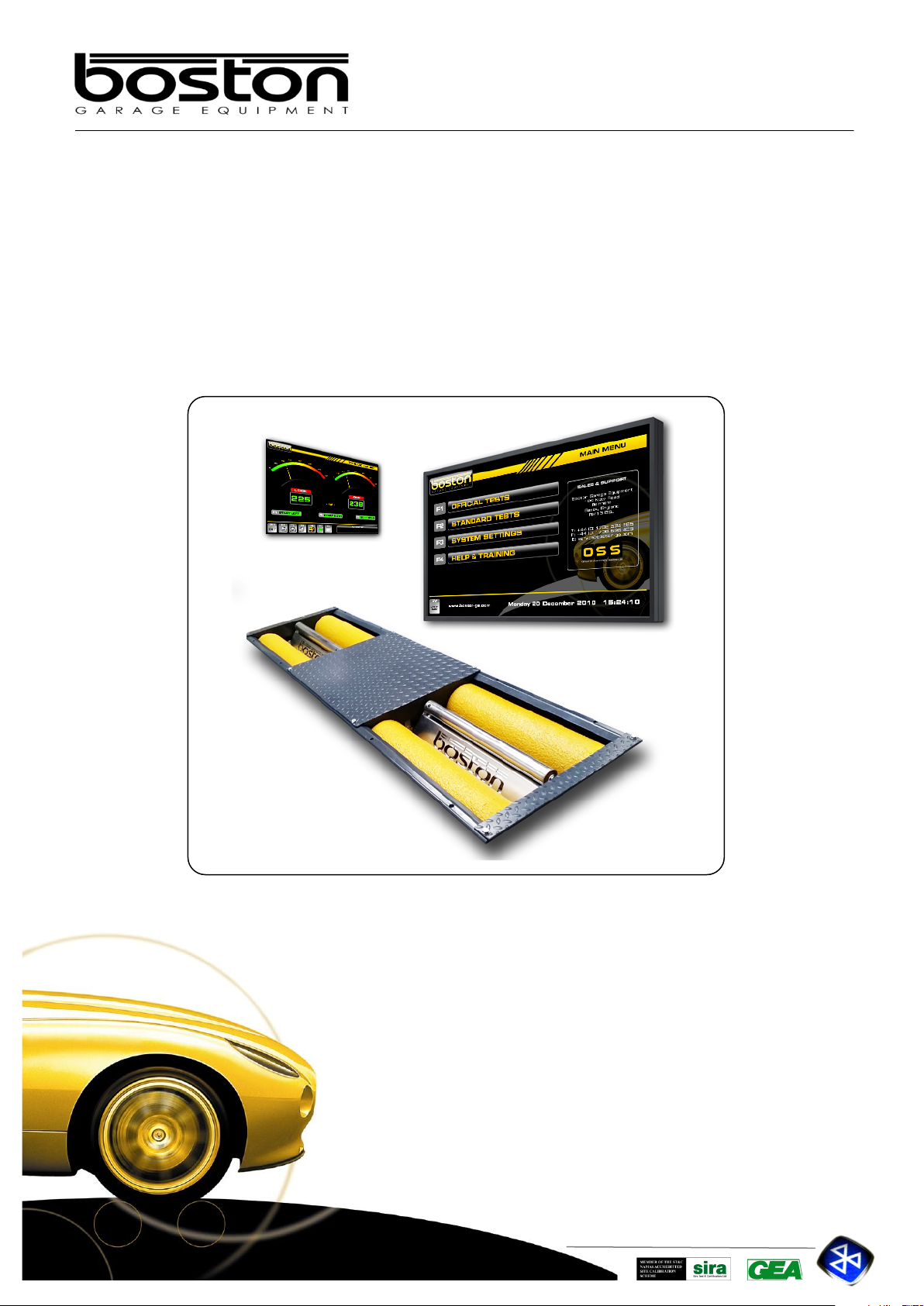
The RBT is a well-known method for analysing the efficiency of the braking system of a vehicle.
There are several main components that comprise the D412 RBT, these are listed below and are covered in
detail later on this chapter.
D412B The steel chassis floor module containing the rollers and all sensors.
MCU-090 A wall mounted cabinet containing the cable connections from the roller bed, data
acquisition circuitry and operation control relay cards.
GCP Boston’s computer control system running the SW900 control software with
mouse, keyboard LCD display monitor and laser printer.
RFC-95 An RF Remote control for remote operation of the RBT from inside the vehicle.
MC1 A small cover plate that attaches to the roller bed to enable the safe testing of
smaller motorcycle wheels.
The mechanical floor unit contains two electrical motors, two independent sets of three measuring rollers, two
brake force transducers, additional safety sensors and an optional four point vehicle weighing system fitted to
the base or installation cartridge.
During testing, the brake forces induce reaction forces on the electric motor which in turn applies force to an
electric transducer with strain gauges. Through software, the sensors are monitored and the data collected is
converted into a reading and displayed on a monitor for the operator to see. The rotating brake rollers are
coated with a wear-resistant material which provides high friction values in both wet and dry conditions. The
roller diameters are sufficiently large to keep the tyre flexing to a minimum.
The third smaller roller on each side between the wheel supporting rollers has two functions:
The first is to detect if a vehicle is present in the roller bed (a built in safety device to prevent the motor
starting without a vehicle in place). For safety purposes, the motors will not start if both the left and
right small rollers are not pushed down for more than two seconds (except when 3-wheel mode or
motorcycle mode is selected).
The second function is to detect if tyre slip on the rollers does not exceed the maximum value.
The GCP control system can be configured in two ways, either wall mounted or fitted into a mobile trolley /
cabinet stand. The GCP that controls the RBT is not connected directly to the roller bed but to the MCU
(Master Control Unit) via USB.
Page 11
DOC: BOS0481
D412 / D412+MC1 USE R MA NUA L
11 / 93
ENGLISH
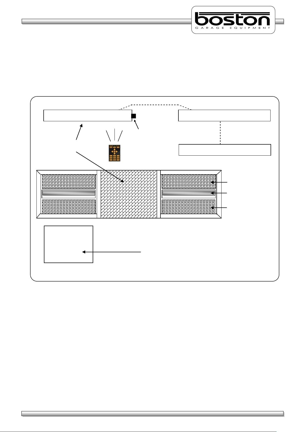
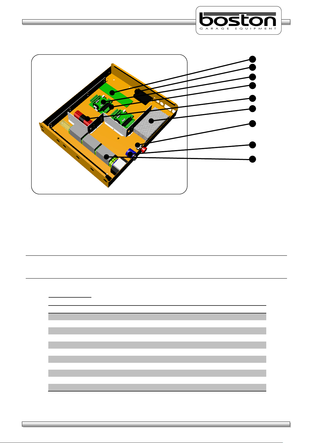
Emergency switch + Main switch
Wall mounted connection / control box
Measuring roller
Measuring roller
Slip detection roller
BSS2000
D412 Roller
The BSS2000 Side-Slip Meter is a separate device and
Wall mounted LCD display unit
GCP – Control System
Remote Control
The MCU is a wall mounted connection panel which the mechanical floor unit is wired to. It contains the
various components to acquire data from the sensors during braking and control relays for starting and
stopping the rollers. It has an emergency stop button and main power switch located on one side of the
panel.
Braketester
Side-Slip Meter
can easily be added to the D412 Roller Braketester.
Page 12
DOC: BOS0481
D412 / D412+MC1 USE R MA NUA L
12 / 93
ENGLISH
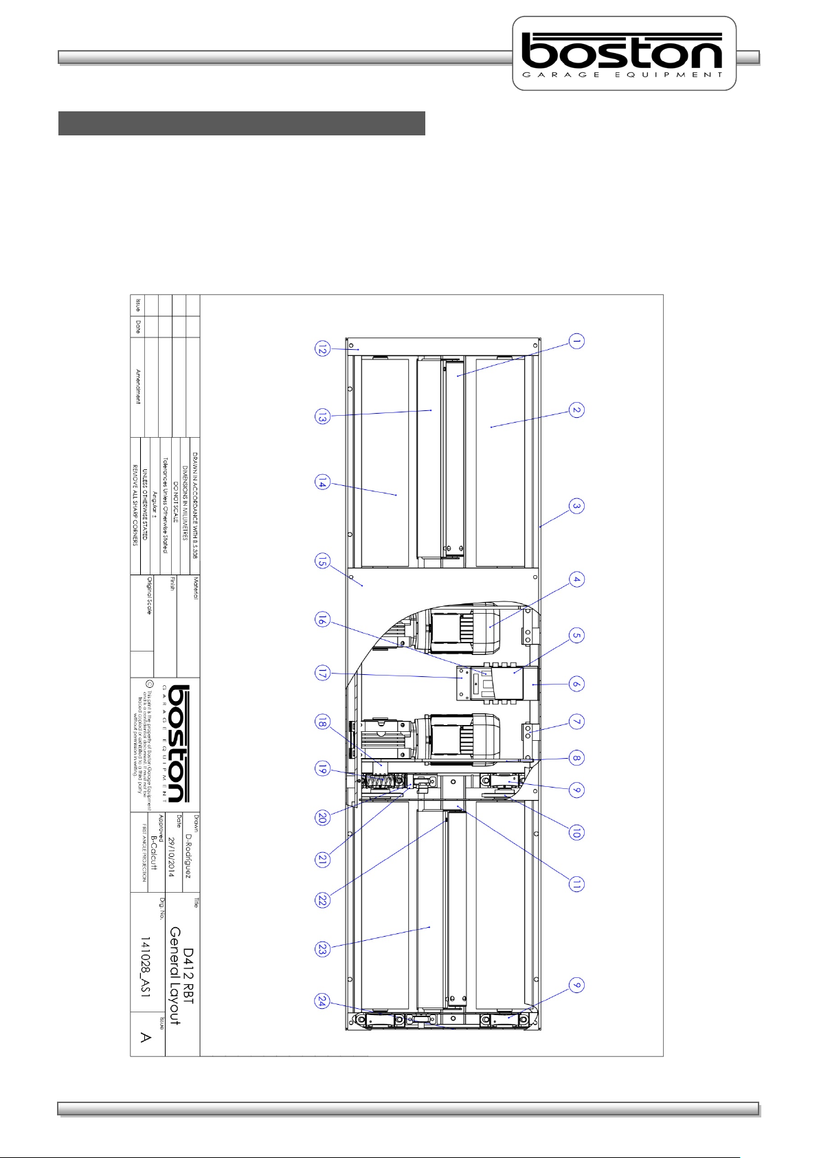
D412B Roller Bed
The D412B Roller Bed is a single chassis unit containing four high friction surface rollers and two smaller
free rolling rollers to detect wheel presence and measure wheel speed. The unit is equipped with two
brake force measurement sensors and can be fitted with an optional vehicle weighing system.
A general layout of the D412B Roller Bed is shown below.-
Page 13

DOC: BOS0481
D412 / D412+MC1 USE R MA NUA L
13 / 93
ENGLISH
Item
Description
Quantity
1
Tacho roller 2 2
Front roller 2 3
Chassis 1 4
Motor 230/400V 3kW
2
5
Connection PCB Enclosure
1
6
Connection Box Support Bracket
1
7
Force Transducer
2
8
Torque Arm
2
9
Bearing Housing
4
10
Chain Roller 4 11
Protection Plate
2
12
Side Covers 2 13
Detection Frame LEFT
1
14
Rear Roller 2 15
Centre Cover Plate
1
16
Connection PCB
1
17
Ground Connector
1
18
Drive Shaft Spacer
2
19
Spring Extension
2
20
Tacho Stop Block
2
21
Rubber Stop
2
22
Proximity Switch
2
23
Detection Frame RIGHT
1
24
End Chassis 2
Component Table
Page 14
DOC: BOS0481
D412 / D412+MC1 USE R MA NUA L
14 / 93
ENGLISH
MCU-090 (Master Control Unit)
The MCU-090 is an interface / connection box where the power cables for the motors and data cables for
the sensors are all connected. Although the MCU-090 is used for the control of the D412B roller bed, it can
also be used to connect and control the following components to provide a full test lane.-
• R102 Class 1,2 Motorcycle Roller Brake Tester
• R103 Class 1,2 Motorcycle Roller Brake Tester
• D402 / D402W+MC1 Class 1,2,3,4 Roller Brake Tester (Manual and Auto Testing)
• D412 / D412W+MC1 Class 1,2,3,4 Roller Brake Tester (Manual and Auto Testing)
• D403 / D403+MC2 Class 1,2,3,4 Roller Brake Tester (Manual and Auto Testing)
• D702 / D702+MC3 Class 1,2,3,4,5L,7 Roller Brake Tester (Manual and Auto Testing)
• D712 / D712+MC3 Class 1,2,3,4,5L,7 Roller Brake Tester (Manual and Auto Testing)
• S402 3T Suspension Tester
• S702 4T Suspension Tester
• SS02 4T Side-Slip Meter
• AGS200 Exhaust Gas Analyser
• AGS688 Exhaust Gas Analyser
• OPA100 Exhaust Diesel Smokemeter
• B502 Electronic Headlight Tester
NOTE
Some items listed above may be under development.
In most cases the MCU-090 will be supplied in standard configuration. This will allow control of the
majority of products above (and some others) simultaneously. Depending on specific customer
requirements, additional internal components may be required.
Page 15
DOC: BOS0481
D412 / D412+MC1 USE R MA NUA L
15 / 93
ENGLISH
Item
Description
1
Connection Interface Card
2
Powered USB Hub
3
Data Acquisition Card 1 (Optional second card can be installed)
4
Relay Card 1 (Optional second card can be installed)
5
Low Voltage Connection Din Rail
6
Power Supply
7
Emergency Stop Button
8
Main Power Switch
9
High Voltage Relay Din Rail
2 8 5 3 6 4 1 9 7
The MCU-090 is connected to the GCP using a standard USB A-B connection cable. Older versions of Boston
Control Platforms may also be used to control the MCU-090, check with your local distributor for
compatibility.
NOTE
There are no user serviceable parts inside the MCU-090 and all maintenance / repairs should be carried out
by approved Boston engineers.
Component Table
Page 16
DOC: BOS0481
D412 / D412+MC1 USE R MA NUA L
16 / 93
ENGLISH
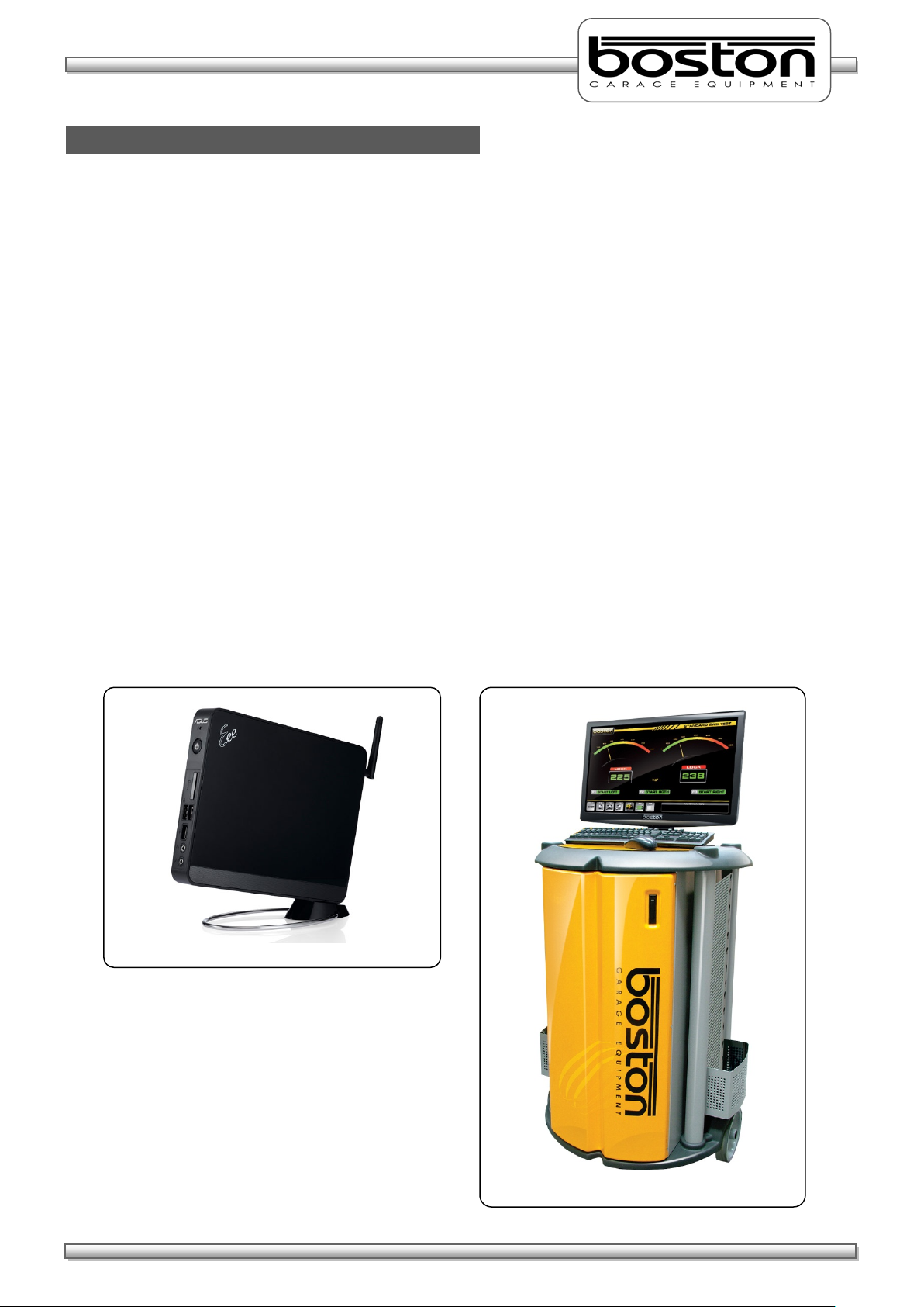
BPC-0951 Mini PC
TRO-220 Mobile Stand
GCP (Global Control Platform)
The GCP is the computer control station that connects to the MCU-090 via USB. It is a separate unit and
can be supplied in different configurations, but in most cases it is wall mounted with a display monitor and
mouse / keyboard (GCP1). A breakdown of the GCP main standard supply components is listed below.-
Mini Industrial PC with Windows OS and Internal Wifi
Boston Software SW900
Optical PC Mouse
PC Keyboard
Widescreen LED Monitor
Laser Printer
Wall mount bracket or rolling stand
The GCP can also be supplied as a mobile unit using one of Boston’s rolling cabinet stands.
GCP3 - Circular Drum-Type Mobile Stand (as shown below)
GCP2 - Standard Mobile Stand
In all cases, the GCP can also be fitted with a second display monitor up to 60” in size. Please contact
Boston or your local sales / service agent for further information.
This manual only covers the Braketester software program; another manual is available separately detailing
the operation and functions of the SW900 software installed on the GCP.
Page 17
DOC: BOS0481
D412 / D412+MC1 USE R MA NUA L
17 / 93
ENGLISH
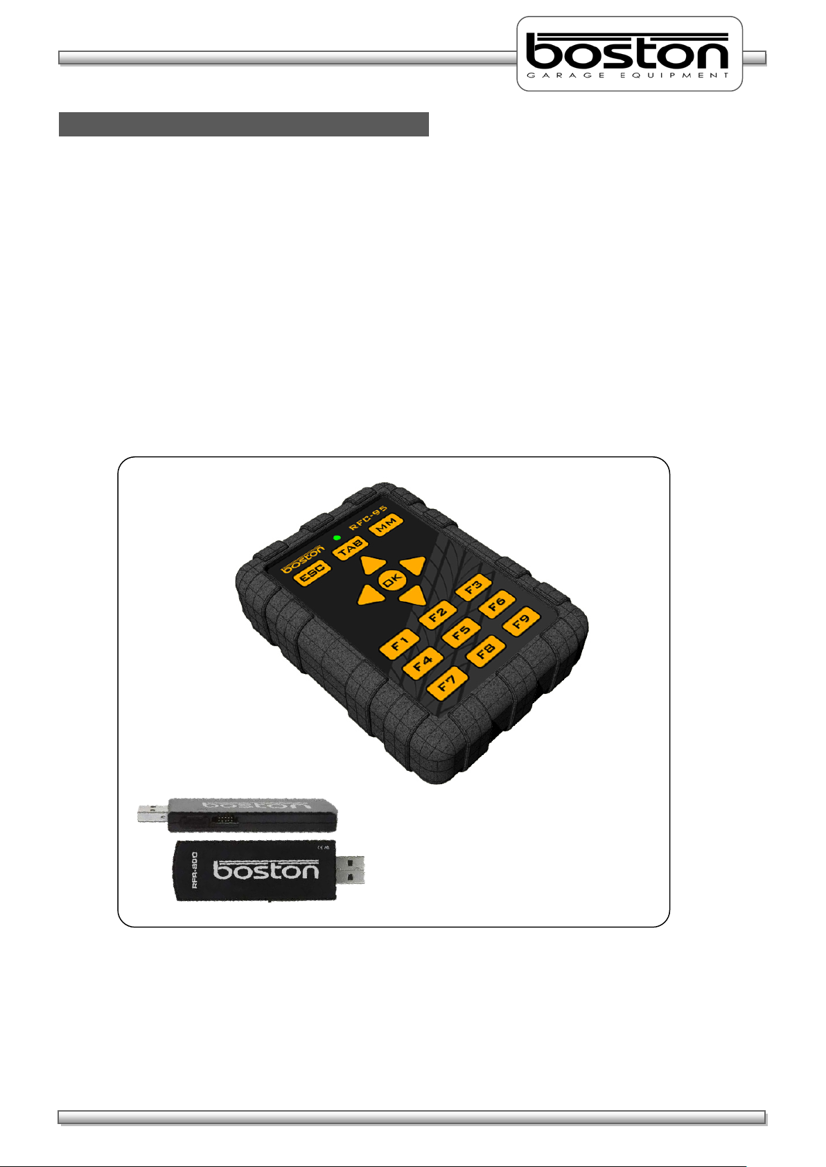
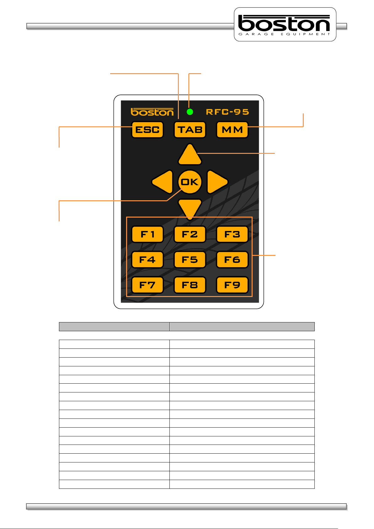
RFC-95 (RF Remote Control)
The remote control is the most commonly used control for the SW900 software. It has many of the same
functions as the keyboard but from a wireless range of approximately 50m. There is a separate User
Manual available for the Boston RF Remote Control, but the main functions are covered here.
Many remote controls operate using infra-red (IR) technology. Whilst being reliable, they are restricted to
‘line-of-sight’ operation which in some environments can make them impractical. The Boston RFC-95 is a
ruggedized control, ideally suited for the testing industry where rugged protection is required. It operates
using the latest Zigbee Radio Frequency (RF), which unlike IR doesn’t require line of sight operation. This
provides greater flexibility and allows it to be used from inside the vehicle to control different items of
equipment.
The RFC-95 button functions are shown below.
Page 18
DOC: BOS0481
D412 / D412+MC1 USE R MA NUA L
18 / 93
ENGLISH
Button
Associated keyboard Function
ESC
ESCAPE
TAB
TAB
MM
MAIN MENU (SW900 Software only)
ARROW UP
ARROW UP
ARROW DOWN
ARROW DOWN
ARROW LEFT
ARROW LEFT
ARROW RIGHT
ARROW RIGHT
OK
ENTER
F1
FUNCTION KEY F1
F2
FUNCTION KEY F2
F3
FUNCTION KEY F3
F4
FUNCTION KEY F4
F5
FUNCTION KEY F5
F6
FUNCTION KEY F6
F7
FUNCTION KEY F7
F8
FUNCTION KEY F8
F9
FUNCTION KEY F9
‘TAB’ Key
‘ESC’ Button
‘MM’ Button
Arrow Keys
‘F’ Keys
‘OK’ Key
keyboard.
Transmission LED
This button duplicates
the ‘Tab’ key function on
the main keyboard.
This button duplicates
the ‘ESC’ key function
on the main keyboard.
This button duplicates
the ‘ENTER’ key
function on the main
The LED illuminates to
confirm any key press.
This button returns the
operator to the Main
Menu (only for Boston
SW-900 software).
These buttons duplicate
the arrow key functions
on the main keyboard.
These buttons duplicate
the ‘F’ key functions on
the main keyboard.
Page 19
DOC: BOS0481
D412 / D412+MC1 USE R MA NUA L
19 / 93
ENGLISH
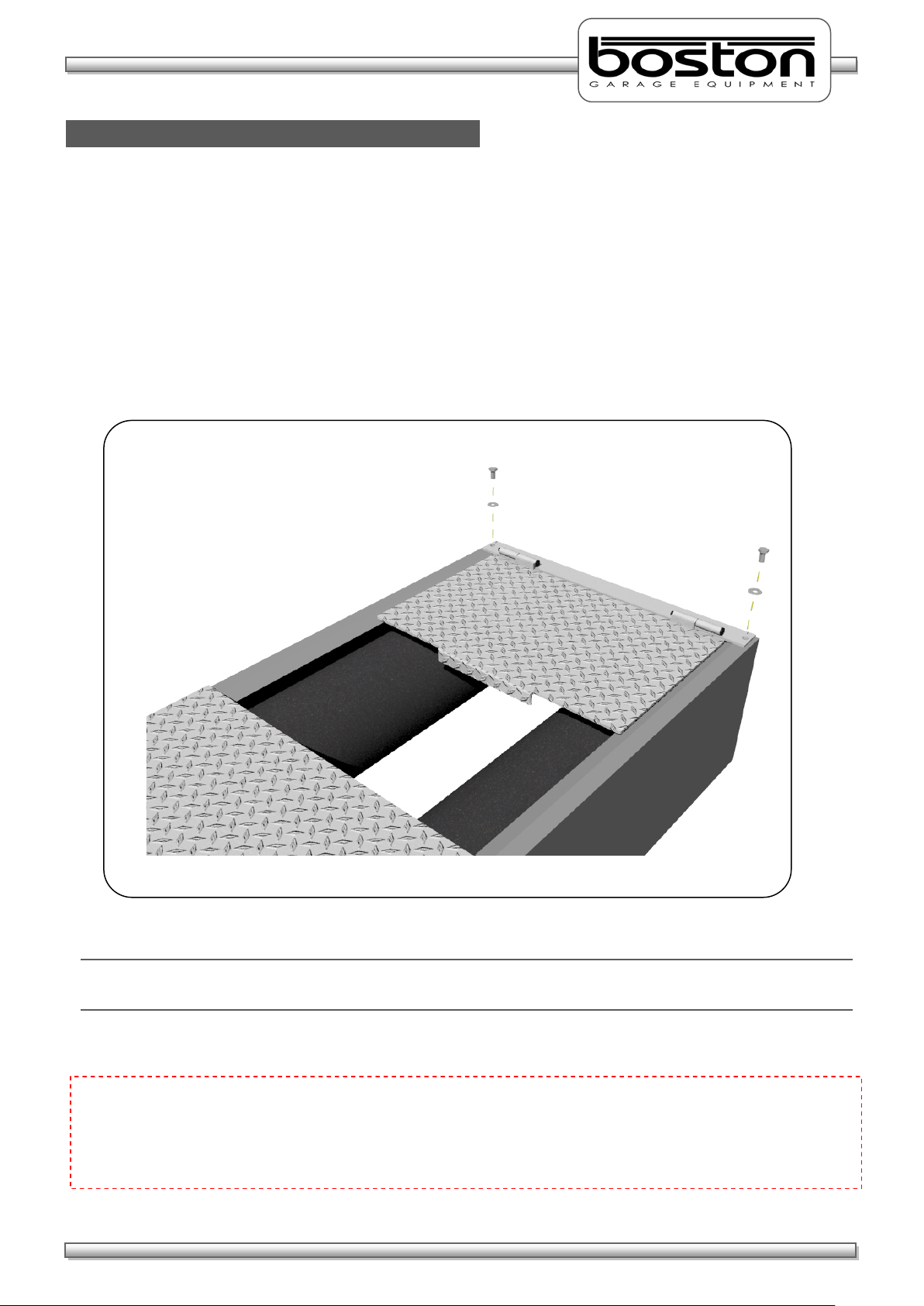
MC1 (Motorcycle Testing Cover Plate)
In order to test motorcycles, it is necessary to fit the MC1 cover plate to the required testing roller. The
cover plate is designed specifically to accommodate motorcycle wheels and safely cover the unused open
portion of the rollers. The cover plate is attached to the roller bed using two bolts and can be fitted very
quickly. It contains two hinges allowing the plate to ‘swing’ into place without the need to permanently
remove from the roller bed.
To fit the cover plate, refer to the illustration below.-
NOTE
The MC1 is a foot plate and is not intended for vehicles to drive over.
CAUTION
Motorcycle testing can only be carried out when the MC1 cover plate adapter has been fitted. The plate
limits the width of the open roller surface to accommodate the narrow wheels of motorcycles. It is
dangerous and prohibited to test motorcycles without the MC1 cover plate fitted.
Page 20
DOC: BOS0481
D412 / D412+MC1 USE R MA NUA L
20 / 93
ENGLISH
General Operation
Chapter 4
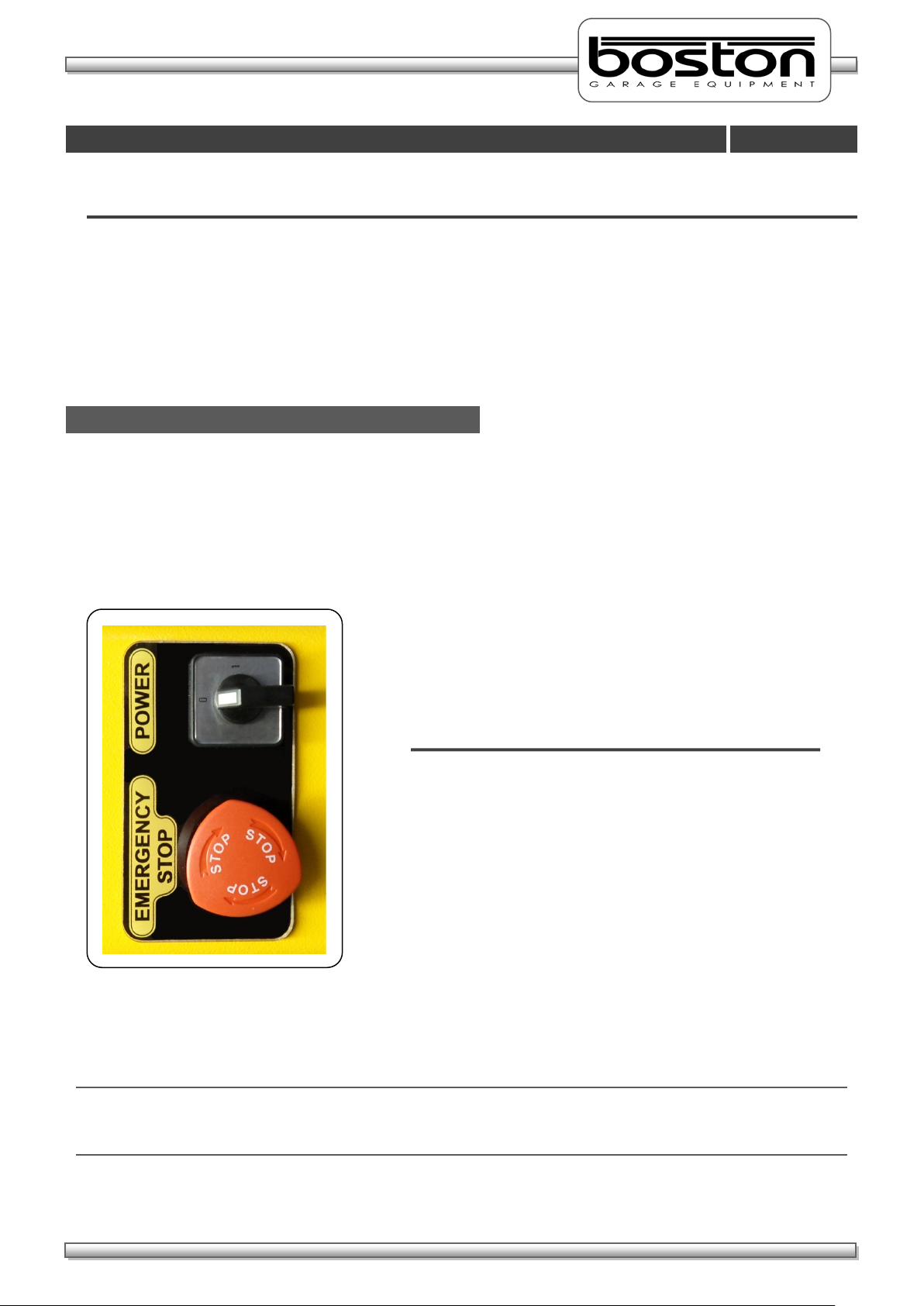
Power On (MCU-090)
MAIN POWER SWITCH - Isolates power from the
EMERGENCY STOP - Immediately stops all
In This Chapter
Power On (MCU-090) 20
Power On (BPC-091) 21
Menu Navigation 21
Mouse Control 22
Keyboard Control 23
Software Version 24
The MCU-090 has a Main Power switch and Emergency Stop button on the side of the cabinet. The Main
Power switch interrupts and isolates the power to the GCP control system and any other connected
equipment. The Emergency Stop button immediately stops all current operations and turns off the control
side of the system. It is usually left in the ‘running’ state and only used in the event of an emergency. The
operation of both these switches is shown below.-
Once power is applied to the MCU-090 the system is ready and waiting for instructions from the PC control
platform.
NOTE
In the wall-mount configuration, the power for the PC, monitor and printer is taken from the MCU-090.
When switching off the main power as described above, remember these items will also be switched off.
entire system and all other
connected equipment.
OPERATION - Rotate switch in clockwise /
anti-clockwise direction.
operations and turns off
power to the control side
of the system.
OPERATION - Press switch to activate.
Rotate clockwise to de activate.
Page 21
DOC: BOS0481
D412 / D412+MC1 USE R MA NUA L
21 / 93
ENGLISH
Power On (BPC-091)
Menu Navigation
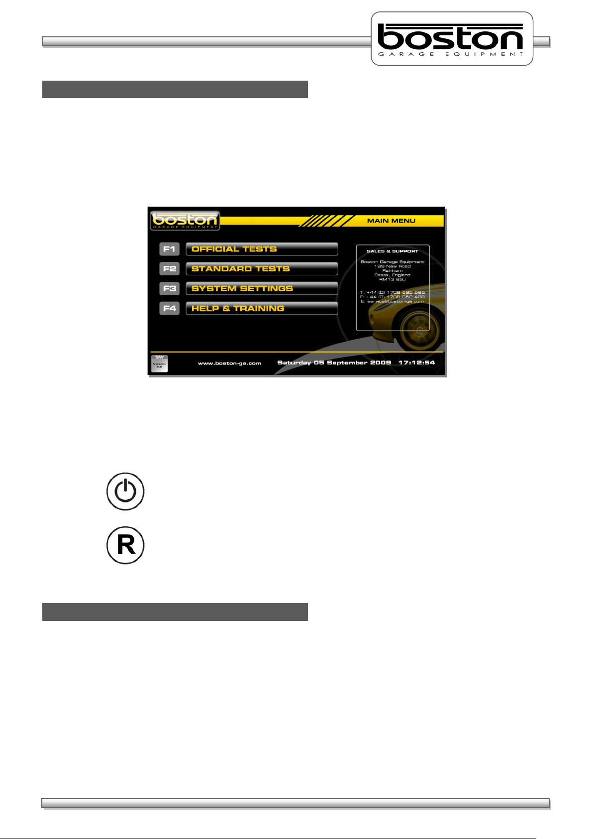
When power is applied to the BPC-091 PC, the system will automatically start-up and enter into the main
software menu page (as shown in the screenshot below). This will happen in the event of a power-cut or
even if the unit has been previously powered down and the power source removed and restored. In all
cases, when power is detected that was previously not present the system will auto-start.
There are also two power buttons on the right side of the PC. These are the main ‘POWER’ button and the
‘RESET’ button. A single press of either will perform the following function:-
POWER Button - Powers down the system. To restart, press the
POWER button again.
RESET Button - Resets the system by powering down and then re-starting
automatically.
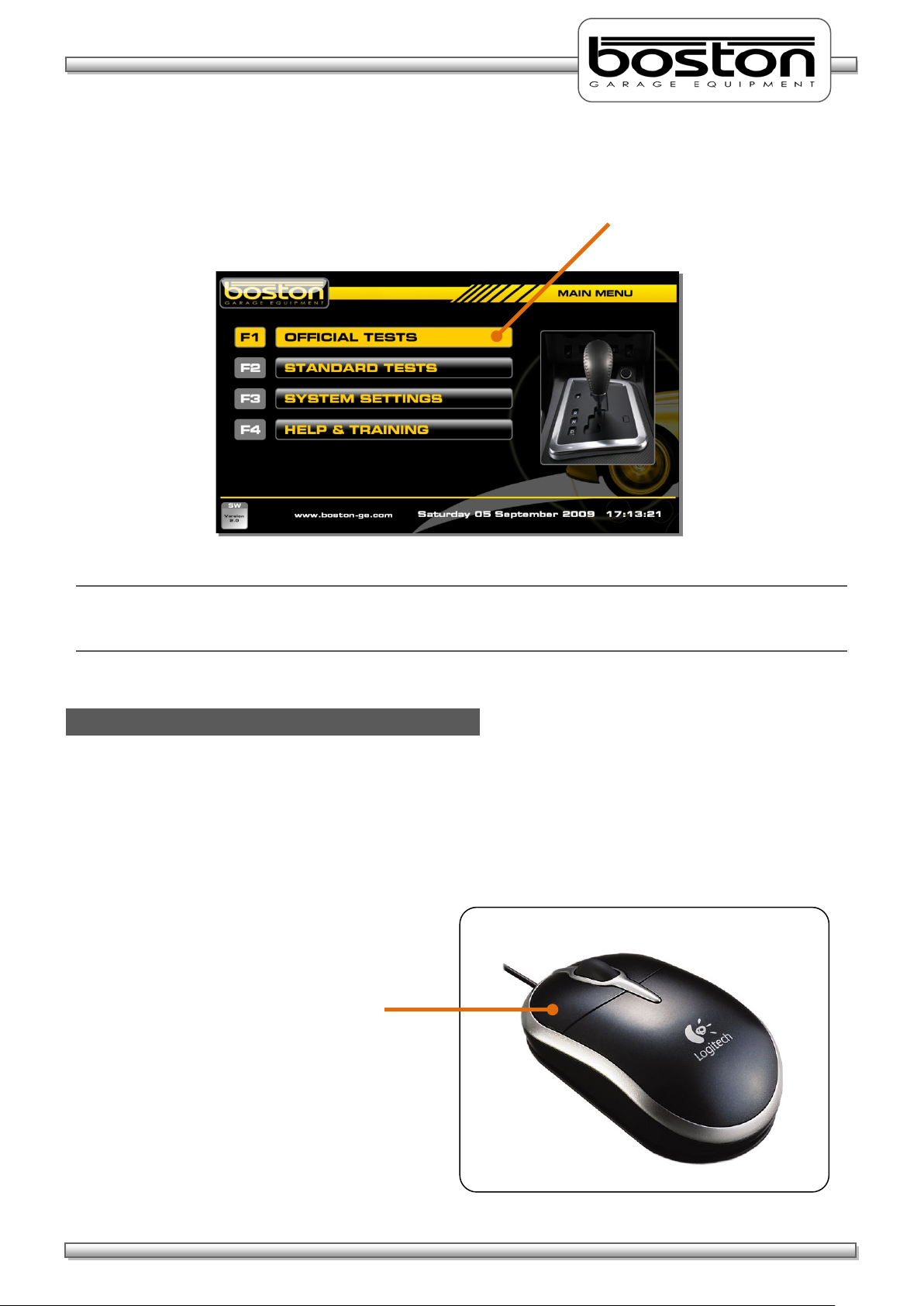
After initial power-on, the page shown above should be displayed. From this page the user can select
whether to perform tests (options F1 and F2) or to change settings (F3) or seek assistance (F4). All options
in the SW900 software are described in detail in the SW900 User Manual available separately. For the
purpose of this manual we shall only cover the operation of the RBT program.
The software can be operated in several ways, either by using the keyboard, the mouse or the remote
control. All three options are available to the user (depending on their preference) and can be used at any
time, and anywhere within the software.
Page 22
DOC: BOS0481
D412 / D412+MC1 USE R MA NUA L
22 / 93
ENGLISH
Option F1 Highlighted
Mouse Control
Click the LEFT button
As the user scrolls through each menu option, it becomes highlighted to indicate the current selection. To
select the highlighted option press the ENTER key on the keyboard. See screenshot below.
NOTE
When using the ‘F’ keys directly, the options are not highlighted but the software continues immediately to
the selected option.
As the mouse pointer is placed on any of the different options, the option becomes highlighted in the same
way as if the keyboard arrows keys or TAB key were being used. As the mouse pointer leaves the option
the highlight is removed. To select any option, place the pointer over the desired option and click the LEFT
button on the mouse. The software will proceed to the selected option.
on the mouse to make
the selection.
Page 23
DOC: BOS0481
D412 / D412+MC1 USE R MA NUA L
23 / 93
ENGLISH
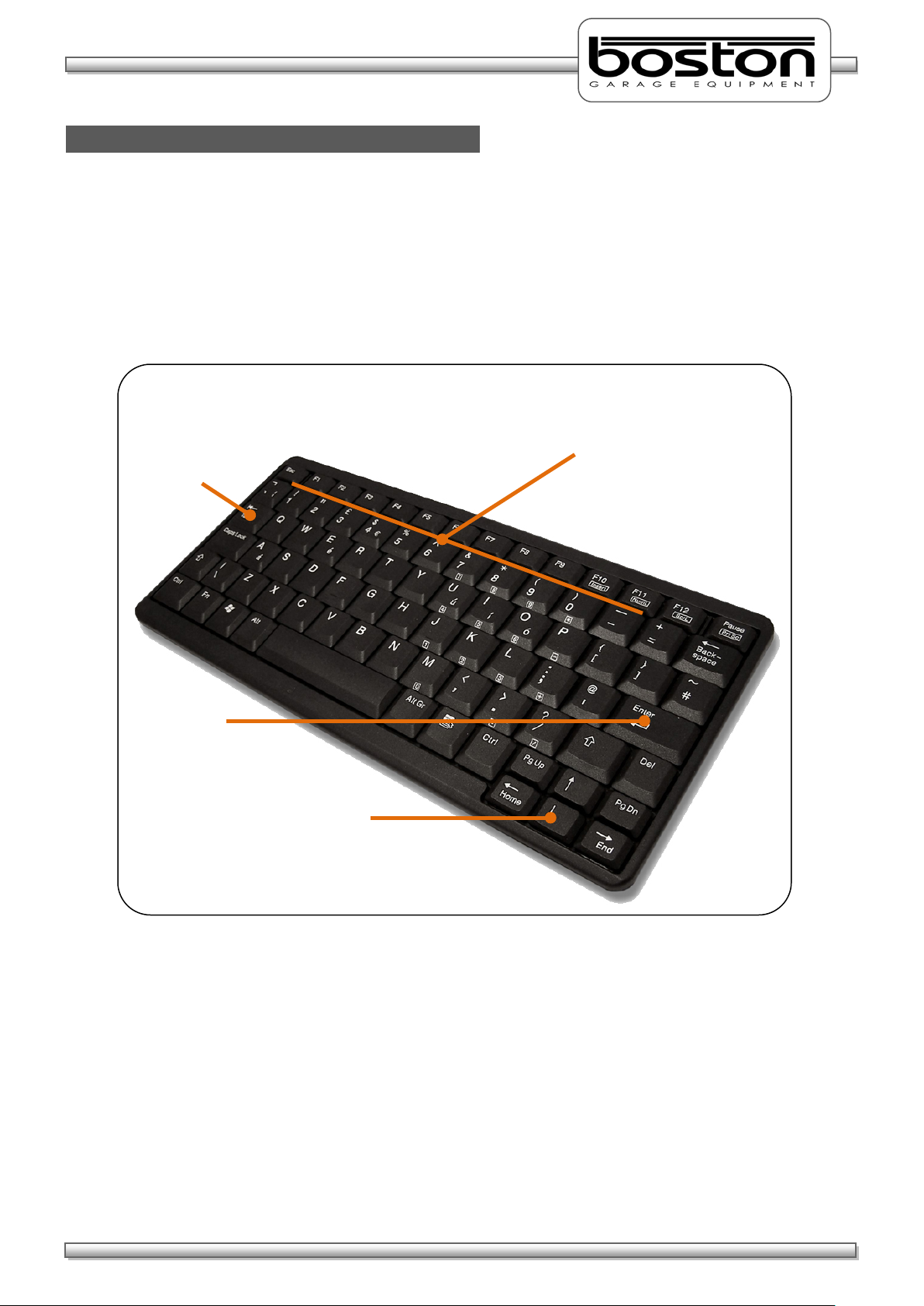
↑
Keyboard Control
Arrow Keys
or to move in
different directions
‘F’ Keys
or to select the
required option directly
Tab Key
Enter Key
The software can be operated from the keyboard in several ways.
By using the
and ↓ ARROW keys to highlight and scroll through the menu options.
By using the TAB key to jump to and highlight the next menu option.
By using the ‘F’ keys along the top of the keyboard to directly select the required option.
This button allows
the operator to jump
directly to the next
menu option.
These buttons allow the
operat
without the need to scroll
through the menus.
The Enter key confirms
the highlighted selection.
These buttons allow the
operat
though the menus.
Page 24
DOC: BOS0481
D412 / D412+MC1 USE R MA NUA L
24 / 93
ENGLISH
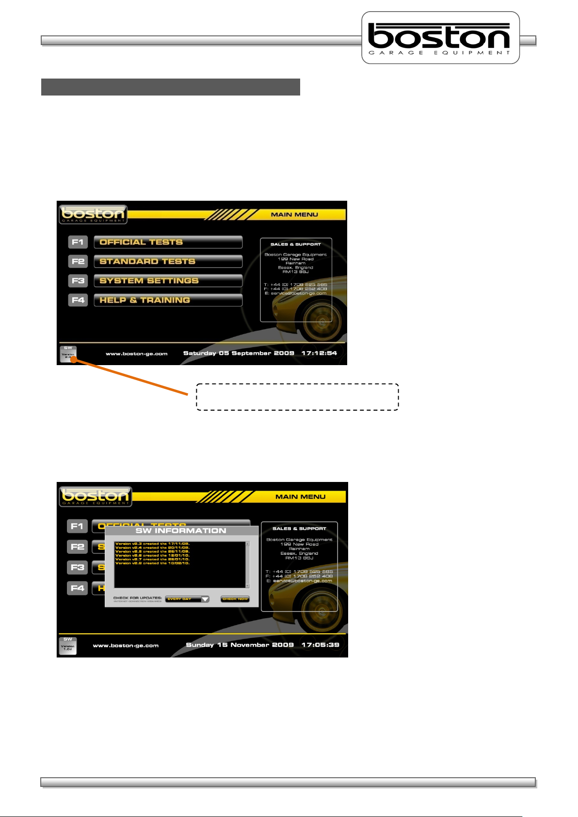
Software Version
The current software version is shown here
As new products become available and changes and additions are made to the various software
procedures, the SW900 software will require updating. To easily find out which software version is
currently being used, simply look at the bottom left-hand corner of any of the MAIN MENU pages.
By clicking on the button with the mouse, a pop-up window will be shown detailing the software version
and changes made in the current version since the previous version. See below.
Software Updates are released periodically throughout the year and it is important that your software is up
to date. Updates can be installed automatically if your system is connected to the internet. If not, your
local agent can install updates on request.
Please see the SW900 USER MANUAL for further information about updating software.
Page 25

DOC: BOS0481
D412 / D412+MC1 USE R MA NUA L
25 / 93
ENGLISH
Standard Brake Test
Chapter 5
In This Chapter
Vehicle Data Entry 26
Display Layout 29
Placing Vehicle in Rollers 31
Vehicle Weight 32
Testing Front Axle 33
Testing for Imbalance 35
Testing Rear Axle 37
Testing the Parking Brake 37
Test Results and Printout 38
Testing 3WD Vehicles 41
Testing 4WD Vehicles 42
Testing Motorcycles 45
Automated Brake Test 58
Saving Test Results 67
This chapter describes how to carry out a STANDARD brake test using both the MANUAL and AUTOMATED
software procedures. The STANDARD TEST option should be used for quick unofficial testing, and the
OFFICIAL TESTS option for official tests. This manual assumes that installation of the RBT is complete and
the software is fully enabled for the user. This manual also assumes that the user is familiar with the
SW900 software and has read the SW900 software manual.
Before continuing, it is important to note and check the following:
Brake forces are indicated in kgf.
Weight input is indicated in kg.
Imbalance is indicated in %.
Brake efficiency is indicated in %.
Examine the tyres to ensure they are not under-inflated, if the tyre pattern is in good condition and
if the tyres are free from mud and stones.
Determine whether the vehicle has a single brake control system or a split (dual) brake control
system.
Ensure the roller covers are removed from the RBT.
Ensure the wheels of the vehicle are always placed centrally in the rollers before starting the test.
Understand the quick stop emergency procedures should they be required.
NOTE
All references on the software pages to the ‘F’ keys on the keyboard also relate to the same function keys on
the RF remote control. The following procedures do not relate to the remote control although the functions
of the keyboard and remote control are the same.
Page 26
DOC: BOS0481
D412 / D412+MC1 USE R MA NUA L
26 / 93
ENGLISH
Vehicle Data Entry
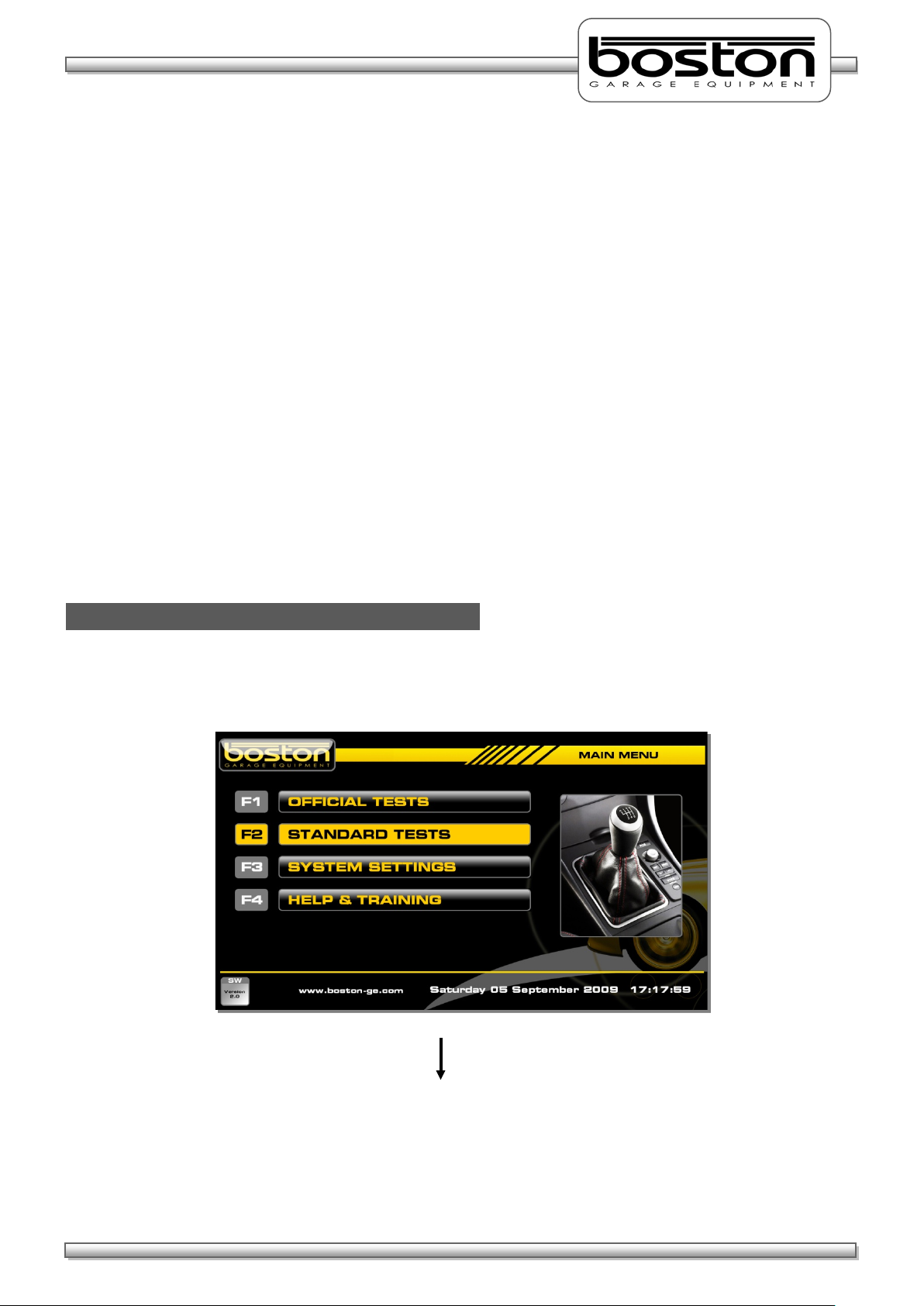
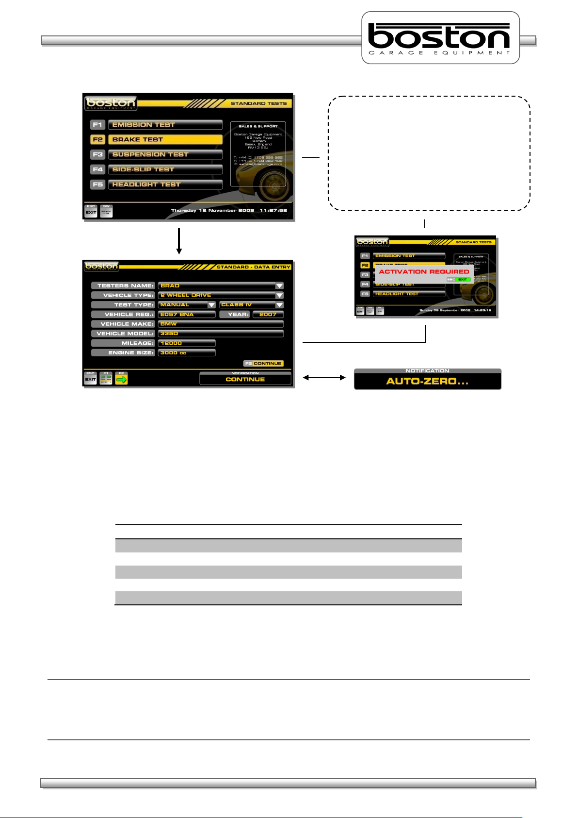
F2 – STANDARD TESTS
The STANDARD BRAKE TEST is usually performed in the following order, but the software is able to
accommodate any other order if preferred by the tester.
1. Service Brake - Front LEFT wheel
2. Service Brake - Front RIGHT wheel
3. Service Brake - Imbalance between both front wheels
4. Service Brake - Rear LEFT wheel
5. Service Brake - Rear RIGHT wheel
6. Service Brake - Imbalance between both rear wheels
7. Parking Brake - Rear LEFT wheel
8. Parking Brake - Rear RIGHT wheel
In some cases, the PARKING BRAKE may act on the front wheels, and it may be necessary to test the
PARKING BRAKE with the front wheels still in the rollers. The list above is just an example of the most
common type of test procedure and is the procedure demonstrated in this manual.
From the MAIN MENU, select option F2 ‘STANDARD TESTS’ and follow the procedure below to reach the
DATA ENTRY page.
Page 27
DOC: BOS0481
D412 / D412+MC1 USE R MA NUA L
27 / 93
ENGLISH
MANUAL TEST OPTIONS
AUTOMATED TEST OPTIONS
Motorcycle Test
2 Wheel Drive Vehicle Test
2 Wheel Drive Vehicle Test
3 Wheeled Vehicle Test
4 Wheel Drive Test
From this page the user selects the type of
F2 – BRAKE TEST
test required. If the relevant hardware and
software is installed the software will
continue into the respective program, if not,
the message ‘ACTIVATION REQUIRED’ is
shown. Similarly, if no tester’s names have
been set, the message ‘SET TESTERS NAMES’
will be shown.
Whenever the DATA ENTRY page is entered, the message AUTO-ZERO will be shown briefly in the
NOTIFICATION box. Whichever item of equipment has been selected from the test selection menu will be
‘zeroed’ prior to carrying out the test. At this point, it is important that the roller bed is clear and the roller
covers are removed. If not, the software will ‘zero’ the system with an inaccurate measurement.
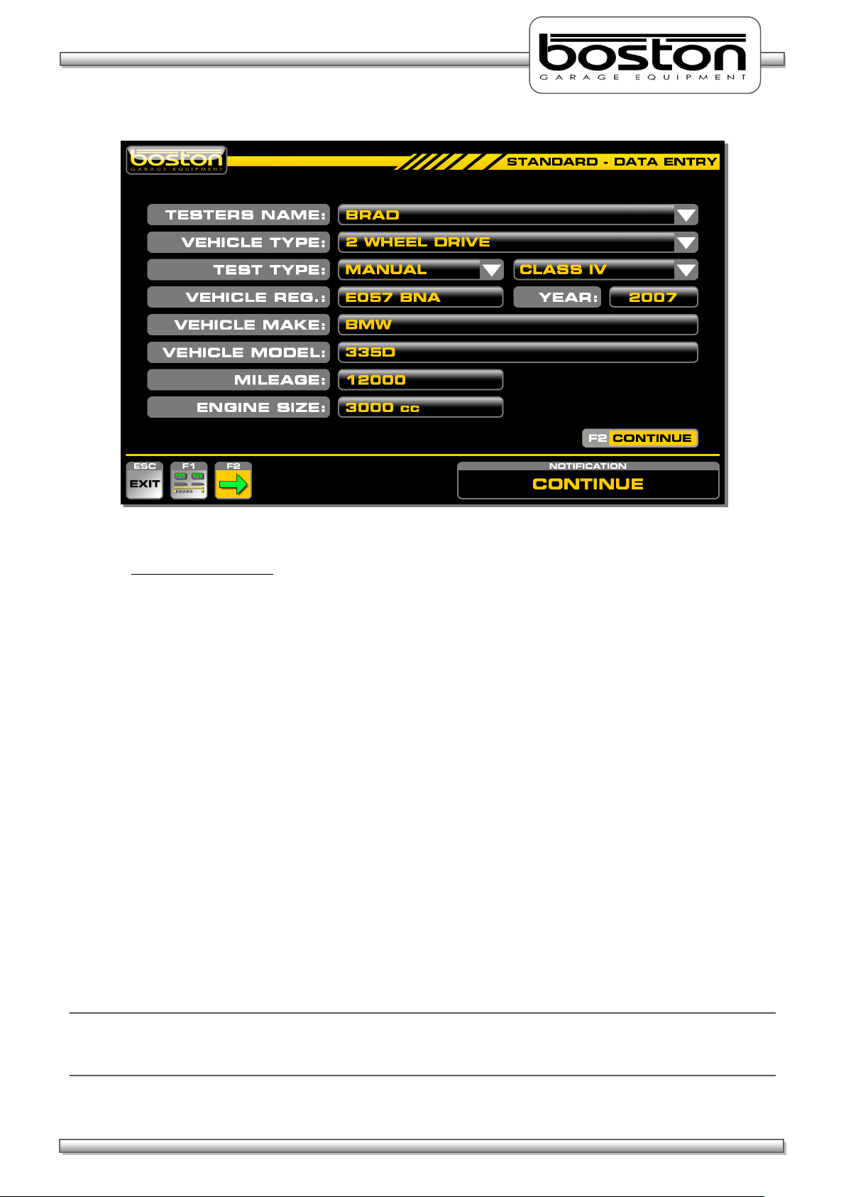
The DATA ENTRY page allows the user to enter specific vehicle data for the vehicle about to be tested. As
the software is able to test different types of vehicles, it is important to ensure that the data is correct
before selecting continue. The available types of test for MANUAL and AUTOMATED are shown below.
Using the mouse and keyboard, enter the relevant information into the DATA ENTRY page. If the operator
does not wish to enter vehicle data, the software will still allow the user to continue, but the missing
information will not be shown on the printout if required.
NOTE
It is not compulsory for the user to enter any vehicle specific data, but the VEHICLE TYPE and TEST TYPE
entry fields must be completed to allow the software to follow the correct route. The default settings for
this page are: 2 WHEEL DRIVE, MANUAL and CLASS IV. The display layout can also be set by selecting F1.
Page 28
DOC: BOS0481
D412 / D412+MC1 USE R MA NUA L
28 / 93
ENGLISH
Test Selection Criteria
If the user selects MOTORCYCLE from the VEHICLE TYPE pull-down menu, the TEST TYPE will
automatically be set to MANUAL, CLASS 2.
If the user selects 4 WHEEL DRIVE as the vehicle type, the TEST TYPE is automatically set to
MANUAL. The option for AUTOMATED is not available.
If the user selects 3 WHEELED VEHICLE as the vehicle type, the TEST TYPE is automatically set to
MANUAL, CLASS 3 (CLASS 4 can still be selected by the user). The option for AUTOMATED is not
available.
If the RBT is fitted with a vehicle weighing system the WEIGHT box is not shown.
The default settings for the DATA ENTRY PAGE are 2 WHEEL VEHICLE, MANUAL and CLASS IV.
The YEAR field is completed automatically by the software depending on the registration of the
vehicle. Eg. If the registration of the vehicle is EO57 then the year is set to 2007. Although this field
is set initially, it can also be edited by the user in the event that the year cannot be ascertained
from the registration number (vehicles with old or personalised number plates).
The data entry on this page is not compulsory and the user can save time by simply selecting
CONTINUE, however, information not entered will not be shown on the printout if required.
The pull-down menus on this page can be operated using the PC mouse, the TAB / ARROW keys on
the keyboard or the remote control.
NOTE
Some of the options mentioned above may not be available. For example, MOTORCYCLE. This option will
only be shown in the pull down list if the product has been purchased and installed.
Page 29

DOC: BOS0481
D412 / D412+MC1 USE R MA NUA L
29 / 93
ENGLISH
Display Layout
F1 – CHANGE DISPLAY
From this page the user selects F1 – CHANGE
Using the mouse, keyboard or remote
From the DATA ENTRY page, it is also possible for the user to select the preferred display layout. There are
three test layouts available as shown in the screenshots below.
To select a preferred layout, select F1 from the DATA ENTRY page as below.
NOTE
For the purpose of this manual, the brake test procedures will be described using the analogue needle
layout where applicable.
At any time during testing the user can change the display to a different layout by selecting F5.
DISPLAY. The following page is shown where
the user can select any of three preferred
layouts.
control, select F1, F2 or F3 to choose a layout.
The chosen layout will be shown on the first
measurement screen after the vehicle has
been placed in the rollers.
Page 30

DOC: BOS0481
D412 / D412+MC1 USE R MA NUA L
30 / 93
ENGLISH
Button
Function
ESC
ESCAPE back to previous page
F1
Start LEFT roller
F2
Start BOTH rollers
F3
Start RIGHT roller
F4
Assign test results to memory
F5
Change display layout
F6
Show results page
At the bottom of the display there are a number of function buttons which are used to control and navigate
the software. The buttons are sometimes different for each page depending on the functions available for
the specific page. For the STANDARD TEST brake test screens, the buttons remain the same irrespective of
the layout chosen by the user. The function of each button is also shown in the NOTIFICATION box when
the user places the mouse over the button.
A layout of the buttons and their respective functions is shown below.
To the right of the function buttons there is a NOTIFICATION BOX. Instructions and messages are shown in
the box for the user to follow. The example below shows the text ROLLER STARTING to alert the user.
Page 31

DOC: BOS0481
D412 / D412+MC1 USE R MA NUA L
31 / 93
ENGLISH
At this point the software is waiting for the
Both wheels have been placed in the rollers
Placing Vehicle in Rollers
Once the DATA ENTRY page has been completed and the preferred display layout has been selected, select
F2 to continue. The software will now ask the user to PLACE VEHICLE IN ROLLERS, see screenshots below.
Once the rollers have been depressed, the detect indicators turn green and the software enters into the
vehicle testing page. From this point onwards the testing procedures may differ depending on the vehicle
details entered on the DATA ENTRY page.
first axle to be placed in the rollers. The two
grey circles indicated as ‘L’ and ‘R’ will turn
green when the respective detection roller
has been depressed by the wheel.
as shown by the two green indicators. This
page is shown only for a few seconds before
the software moves on to the vehicle testing
page.
Page 32

DOC: BOS0481
D412 / D412+MC1 USE R MA NUA L
32 / 93
ENGLISH
Vehicle Weight
The total vehicle weight should be entered
From the testing page select F1, F2 or F3 to
start the rollers. The software will
The SW900 control software automatically detects if a weighing system has been fitted to the D412B Roller
Bed. If so, the WEIGHT box on the DATA ENTRY page is not shown. If the system is not fitted with a
weighing facility then the operator should enter the total vehicle weight in the WEIGHT box on the DATA
ENTRY page. Although this is not compulsory, it is required if the user wishes the software to make the
overall brake efficiency calculations.
here if the weighing system is not fitted to
the roller bed.
The software will acquire the axle weight automatically when the user starts either roller for the first time
for each axle. The message ACQUIRING AXLE WEIGHT is shown while the system checks for a stable
weight. The acquired axle weight is shown shortly after. See screenshots below in sequence. Once the
weight has been acquired the software reverts back to the testing page and the selected roller(s) will start.
There is an audible warning and warning text in red to alert the user.
automatically acquire the axle weight.
Page 33

DOC: BOS0481
D412 / D412+MC1 USE R MA NUA L
33 / 93
ENGLISH
Testing Front Axle
The user selects F1 and the rollers are about
In this example, the left roller has been
After the axle weight has been acquired the operator is warned by on-screen prompts in red and an audible
buzzer that the rollers are about to start. See below.
NOTE
Whenever the rollers are running, the corresponding results box is shown in red. This applies to all screen
layouts.
In order to quickly describe the front axle test, the test procedure below is shown in sequential list format
with simple graphical illustration.
1. Place the front wheels in the rollers as instructed by the software.
2. Select ‘F1 - START LEFT’. The software will first carry out the automatic weighing of the axle, then
an audible alarm will sound and the roller will start. The outer box on the active roller will also
flash red to indicate that the roller is running.
selected. There is an audible buzzer and
three flashes of the red box to alert the user.
The message ‘ROLLER STARTING’ is also
shown in the notification box.
to start
Page 34

DOC: BOS0481
D412 / D412+MC1 USE R MA NUA L
34 / 93
ENGLISH
Left roller is running and brake force is being
Left roller has stopped due to wheel lock.
corresponding reading. The highest brake
Left roller stopped by the user using the
3. Slowly apply force to the brake pedal and observe the real-time reading increase on the display.
4. Continue to apply brake force until maximum force or wheel-lock is achieved. If wheel- lock occurs
a red indicator will be shown on the display. At the point where the tyre slips on the roller the
motor will be stopped immediately to avoid unnecessary tyre wear.
5. If wheel-lock cannot be reached while maximum brake force is being applied the rollers can be
stopped by pressing the F1 key again (or any other key).
slowly applied.
The wheel-lock indicator is shown above the
force reading achieved is shown in the results
box.
remote control or keyboard. The wheel-lock
indicator is not shown but the highest brake
force reading achieved is shown in the results
box.
Page 35

DOC: BOS0481
D412 / D412+MC1 USE R MA NUA L
35 / 93
ENGLISH
Even though the RIGHT wheel was tested, the
The rollers have started and brake effort is
and analogue format using two different
Testing for Imbalance
NOTE
Whichever means of stopping the rollers was used, the display will show the highest brake force achieved
in the left hand display. The needle pointer will also indicate the same value on the analogue dial.
6. Now that the result has been obtained for the LEFT wheel, carry out the same procedure for the
RIGHT wheel using the F3 key to start the roller.
result for the LEFT wheel still remains shown
for comparison. The right wheel result is
shown in the corresponding result box.
7. Now that the service brake has been tested for both front wheels, the brake imbalance must be
checked between them. To do this, both rollers are started together and the difference in brake
force between the two wheels is measured as the brake effort is applied. Select F2 – START BOTH.
The screen design changes slightly to show a single analogue scale. Without applying the brakes,
note if any significant brake force (rolling resistance) is recorded from any wheel.
gradually applied. Both readings for LEFT and
RIGHT can be seen together in both digital
colour needle pointers. This gives a good
indication of severe imbalance if present.
Page 36

DOC: BOS0481
D412 / D412+MC1 USE R MA NUA L
36 / 93
ENGLISH
The rollers have stopped and the LEFT and
Select F7 to assign all the results from the
This test does not require the user to apply maximum brake effort to the pedal. Instead, the user
should aim to stop just short of the maximum value achieved during the individual left and right
wheel brake force measurement and then slowly reduce brake effort to a minimum. The software
will automatically stop the rollers when either reading falls below 35kgf.
NOTE
The software disregards any service brake imbalance when the brake effort from each of the front wheels is
less than 40kgf. The software will show the brake imbalance when brake effort from one wheel is greater
than 40kgf.
After the rollers have stopped, the results of maximum IMBALANCE achieved throughout the test
are shown on the display. The readings shown are those which were used to calculate the
imbalance percentage as shown in the centre result box. Refer to Chapter 5 for permissible limits.
8. Once all tests have been completed for the front axle, the user can save them to be used in the
overall brake efficiency calculation. To do this, select F4 ASSIGN TEST DATA and select where to
save the results. As this is a FRONT AXLE test, select F7 to ASSIGN FRONT AXLE.
RIGHT readings display the values used to
calculate the imbalance result shown in the
centre result box.
FRONT AXLE test to memory.
Page 37

DOC: BOS0481
D412 / D412+MC1 USE R MA NUA L
37 / 93
ENGLISH
Testing Rear Axle
Select F8 to assign all the results from the
Testing the Parking Brake
Select F9 to assign the results for the PARKING
9. To test the rear axle, drive the vehicle forward and place the rear wheels in the RBT. Repeat steps
1 to 8 above but when assigning the test results, select F8 ASSIGN REAR AXLE to store in the correct
memory location. If the F7 ASSIGN FRONT AXLE is selected, the previous test results will be
overwritten.
NOTE
Once the vehicle axle leaves the RBT for more than 2 seconds, the RBT will re-weigh the axle before starting
the rollers. The software recognises the need to weigh the rear axle as the time period between the front
axle exiting the RBT and the rear axle entering the RBT will always exceed 2 seconds. However, this time
period also allows the RBT to re-test the front axle should it become ejected from the rollers during a test.
As the exit duration is usually less than 2 seconds the RBT will not re-weigh the axle.
REAR AXLE test to memory.
10. The parking brake is tested in the same way as the service brake but instead the user operates
the vehicle’s parking brake (numbers 2 to 6). If the parking brake is located on the front axle then
the user should perform the parking brake test before placing the rear axle in the rollers. The same
applies if testing the rear axle first.
BRAKE to memory.
Page 38

DOC: BOS0481
D412 / D412+MC1 USE R MA NUA L
38 / 93
ENGLISH
Test Results and Printing
Vehicle Specific
Vehicle Results
Once the full test has been completed and all results are saved in their respective locations, select F6 –
TEST RESULTS. The following results page will be shown.
Data
Table
The results page contains two main sections, vehicle specific information (as entered by the user at the
beginning of the test) and the results table.
The vehicle data is shown at the top of the page. If the RBT is fitted with a vehicle weighing system, the
weight for both the front and rear axles is shown individually. If the user entered the total weight at the
beginning of the test, the ‘AXLE WEIGHT’ line will not be shown.
The test results grid contains all the results as stored by the user during the test. Only if all results were
stored correctly can the software calculate the correct brake efficiencies. In the example above, all data
has been saved and we can see the efficiencies calculated on the right side of the table.
The results shown in red indicate that the wheel locked during the test, so this test shows that all wheels
locked including the parking brake. If we compare the results of this test against the MOT limits, we can
see that the vehicle has passed on SERVICE BRAKE efficiency as the total efficiency of 114% is much higher
than the 50% required. Similarly, the PARKING BRAKE achieved a total brake efficiency of 57%, more than
the minimum 25% required. Finally, as the BRAKE IMBALANCE is below 25% on the front axle, this vehicle
meets the PASS criteria for an official test.*
As this is a MANUAL UNOFFICIAL test, the software does not generate or display a PASS or FAIL result.
However, from this page the user can choose to print the results as many times as required by selecting the
F1-PRINT button. The printout contains all the same information that is shown on this page together with
the testing station information. A sample printout can be seen on the following page.
* - limits specified may change for vehicles of different ages and types
Page 39

DOC: BOS0481
D412 / D412+MC1 USE R MA NUA L
39 / 93
ENGLISH
The garage logo can be
further information.
This section contains
This section contains
and the tester.
This section contains
This section contains
This section shows
D412+MC1
Sample Printout from a STANDARD TEST
placed here if required. See
the SW900 User Manual for
information about
the test equipment
and when the test
was carried out.
information about
the testing station
information about
the vehicle as
entered by the user
at DATA-ENTRY.
the test results
notes automatically
generated by the
software about the
test.
Page 40

DOC: BOS0481
D412 / D412+MC1 USE R MA NUA L
40 / 93
ENGLISH
Button
Function
ESC
ESCAPE back to previous page
F1
Print results
F2
Save customer details and test results
F3
Repeat the test on the same vehicle (no data-entry required)
F4
Start a new test
The buttons at the bottom of the display offer the user some other options. A list of the button functions is
shown below.
Page 41

DOC: BOS0481
D412 / D412+MC1 USE R MA NUA L
41 / 93
ENGLISH
Testing 3 Wheeled Vehicles (3WV)
Only one DETECT roller needs to be
Three wheeled vehicles can only be tested in the MANUAL mode. They are tested in much the same way as
standard four wheeled vehicles but because one axle has a single wheel, the user must choose which roller
is used to test it.
The following procedure should be followed to test three wheeled vehicles.
Complete the DATA ENTRY page as before but select 3 WHEEL VEHICLE as the vehicle type. The TEST TYPE
will be set to MANUAL and the class of test to CLASS III as default. The user can also set the class of test to
CLASS IV should the weight of the unladen vehicle exceed 450kg. Select CONTINUE.
The PLACE VEHICLE IN ROLLERS page is now shown. When testing a standard 4 wheeled vehicle, both
detect rollers must be depressed before the software will continue into the test program, when testing a 3
wheeled vehicle, either roller can be depressed and the software will continue.
Place either axle in the rollers, although usually the front axle contains the single wheel and is tested first.
When the wheel is inserted, the wheel detect indicator turns green.
depressed. The user can select either roller
for testing.
Page 42

DOC: BOS0481
D412 / D412+MC1 USE R MA NUA L
42 / 93
ENGLISH
The page title at the top right will indicate
Testing Four Wheel Drive Vehicles (4WD)
After testing the single wheel, the user should save the test result to the relevant axle in the same way as
for the standard test.
Drive the vehicle out of the rollers and place the second axle to be tested in the RBT. Now perform the
individual LEFT and RIGHT SERVICE BRAKE tests as described in numbers 2 to 6 above and assign the results
to relevant axle.
Perform the IMBALANCE test on the two-wheeled axle as described in number 7 above.
To view the results select F6 and print as necessary.
Four wheel drive vehicles can only be tested in the MANUAL mode. They are tested in much the same way
as standard four wheeled vehicles but because the wheels of a single axle (or multiple axels) are sometimes
permanently connected together, it is necessary to rotate the opposite wheel under test in the opposite
direction to avoid damage to the transmission.
This means that during the testing of the FRONT LEFT wheel, the RBT will also start the FRONT RIGHT roller
but in the opposite direction.
NOTE
Always refer to the manufacturer’s specifications before testing 4WD vehicles. Some types of 4WD vehicles
cannot be tested on the RBT and as such it is the user’s responsibility for ascertaining the type of
transmission being tested. Always ensure that the correct buttons on the remote control are used.
CAUTION
During the testing of 4WD vehicles, the opposite brake roller will operate in the reverse direction.
3WV test.
For testing the single wheel, the user can
only use the roller that detected the wheel,
the other roller will not operate without a
wheel present.
Page 43

DOC: BOS0481
D412 / D412+MC1 USE R MA NUA L
43 / 93
ENGLISH
Both wheels have been placed in the rollers
The following procedure should be followed to test 4WD vehicles.
Complete the DATA ENTRY page as before but select 4 WHEEL DRIVE as the vehicle type. The TEST TYPE
will be set to MANUAL. Select F2 CONTINUE.
The PLACE VEHICLE IN ROLLERS page is now shown. Insert the front axle of the vehicle into the RBT. Both
detect rollers must be depressed before the software will continue into the test program.
as shown by the two green indicators. This
page is shown only for a few seconds before
the software moves on to the vehicle testing
page.
Page 44

DOC: BOS0481
D412 / D412+MC1 USE R MA NUA L
44 / 93
ENGLISH
The page title at the top right will indicate
During the testing of the FRONT LEFT wheel, the text 4x4 is shown in the right side results box. The right
side roller is also operating but in the reverse direction.
During the testing of the FRONT RIGHT wheel, the text 4x4 is shown in the left side results box. The left
side roller is also operating but in the reverse direction. In this display layout, the analogue needle pointer
is removed from the inactive measurement display.
After the LEFT and RIGHT wheels have been tested individually, the IMBALANCE test can be carried out in
the normal way.
Once the IMBALANCE test is complete and all data has been saved, drive the vehicle forward and place the
REAR wheels in the rollers.
Repeat the procedure for the SERVICE BRAKE REAR and the PARKING BRAKE, and save the data to the
relevant axle using F4 on the keyboard or remote control.
4WD test.
The text 4x4 is shown in the opposite display
when testing 4WD vehicles. The active roller
under test shows the live data.
Page 45

DOC: BOS0481
D412 / D412+MC1 USE R MA NUA L
45 / 93
ENGLISH
Testing Motorcycles
Unlike most Class 4 RBT’s, the D412 is able and approved to test motorcycles (provided the motorcycle
software has been installed). This is a very useful and cost effective solution as separate roller beds for
motorcycles can be expensive. The testing procedure is similar to the standard vehicle test although only
one roller is used.
CAUTION
Motorcycle testing can only be carried out when the MC1 cover plate adapter has been fitted. The plate
limits the width of the open roller surface to accommodate the narrow wheels of motorcycles. It is
dangerous and prohibited to test motorcycles without the MC1 cover plate fitted.
For official testing, there are DVSA regulations where testing bays have specific dimensional requirements.
It is important that these are adhered to if the user intends to carry out official motorcycle testing using the
D412. This section covers STANDARD TESTS only; official testing is covered later on in the manual.
To perform a motorcycle test, ensure the MC1 cover plate is securely fitted (refer to Chapter 3 - MC1
Motorcycle Testing Cover Plate) and follow the procedures below.
Testing Motorcycles with Single Brake Control Systems
Complete the DATA ENTRY page as before but select MOTORCYCLE as the vehicle type. The TEST TYPE will
be set to MANUAL and the class of test to CLASS II. Select CONTINUE.
The PLACE VEHICLE IN ROLLERS page is now shown. When testing a standard 4 wheeled vehicle, both
detect rollers must be depressed before the software will continue into the test program, when testing a
motorcycle, either roller can be depressed and the software will continue.
Place either wheel in the rollers, although usually the front wheel is tested first. When the wheel is
inserted, the wheel detect indicator turns green. Make sure that the motorcycle is positioned in a straight
line and that it is not in gear. The rider should sit on the motorcycle as in a normal situation.
Page 46

DOC: BOS0481
D412 / D412+MC1 USE R MA NUA L
46 / 93
ENGLISH
Only one DETECT roller needs to be
In this example we have used the LEFT roller
F5
At this point, whichever roller has been depressed by the user to carry out the test is the roller that should
be used for testing the whole motorcycle. The software will disable the opposite roller until a new DATA-
ENTRY page is completed and the user chooses a roller for the first time.
depressed. The user can select either roller
for testing but once selected this roller must
be used for the duration of the test.
for testing the motorcycle..
The motorcycle layout displays are a little different from the standard layouts. This is because there are no
LEFT and RIGHT readings as motorcycles only have FRONT and REAR readings (and sidecar if fitted). This
display shows a single scale to display the force from a single brake system, the weight obtained from the
wheel being tested and the efficiency result at the end of the test.
The motorcycle procedure can also be carried out using the horizontal bar display layout (as above). The
user can choose to ‘toggle’ between the two layouts by selecting F5.
Page 47

DOC: BOS0481
D412 / D412+MC1 USE R MA NUA L
47 / 93
ENGLISH
Button
Function
ESC
ESCAPE back to previous page
F1
ASSIGN result to BRAKE CONTROL 1
F2
START ROLLER
F3
ASSIGN result to BRAKE CONTROL 1
F4
ASSIGN measured weight to SIDECAR
F5
Change display layout
F6
Show results page
At the bottom of the display there are a number of function buttons which are used to control and navigate
the test procedure. The buttons are sometimes different for each page depending on the functions
available for the specific page. For the STANDARD TEST motorcycle brake test screens, the buttons remain
the same irrespective of the layout chosen by the user. A layout of the buttons and their respective
functions is shown below.
To the right of the function buttons there is a NOTIFICATION BOX. Instructions and messages are shown in
the box for the user to follow. The example below shows the text ROLLER STARTING to alert the user.
Page 48

DOC: BOS0481
D412 / D412+MC1 USE R MA NUA L
48 / 93
ENGLISH
From the testing page select F2 START ROLLER
F2 – START ROLLER
The user must remain steady on the
The measured weight is shown for
Testing the Front Wheel
Once the front wheel is in the rollers the following page is shown.
to start the roller. The software will
automatically acquire the axle weight.
motorcycle to ensure an accurate weight
measurement.
approximately 3 seconds before the display
returns back to the testing page.
As before, the user is alerted to the rollers starting by means of the audible buzzer and the flashing red
indicators on the display. When the roller starts, carefully position the wheel in the centre of the roller
before applying the brake. This is important with larger / heavier motorcycles as they can be difficult to
handle.
Page 49

DOC: BOS0481
D412 / D412+MC1 USE R MA NUA L
49 / 93
ENGLISH
The efficiency will be calculated after the
brake force measurement has been
ASSIGN front wheel brake force measurement
With the roller running, slowly apply brake force to the first brake control (BC1) until the wheel locks or
maximum force is achieved. If the roller cannot be locked then stop the roller by pressing any key on the
remote control or keyboard. The highest brake force reading achieved will be displayed.
completed.
Once the brake force reading has been taken, the user must assign the result to memory. Select F1 or F3
depending on which brake control was used. For this example we will assume this test is the FRONT wheel
using the HAND brake control BC1.
Select F1 (BC1) and assign the reading to the FRONT by selecting F7.
from brake control 1 to the FRONT.
Page 50

DOC: BOS0481
D412 / D412+MC1 USE R MA NUA L
50 / 93
ENGLISH
Brake force fluctuations (Ovality)
After the brake force measurement has been assigned, the operator can test the front wheel for brake
force fluctuations. Follow the procedure below:
Select F2 to re-start the roller (if the wheel has been removed from the roller for more than 2
seconds then weight measurement will be re-taken, but the weight value is not required for this
test).
With the roller running, slowly increase the brake force and hold it steady at a constant value of
approximately half the maximum value measured in the first test. Visually check for brake force
fluctuations on that wheel. Fluctuations are easier to see on the analogue graphical display.
The user should note and interpret any irregularities in the brake force behaviour.
Release the brake quickly and observe the way in which the braking effort reduces.
Press any key to stop the rollers
Page 51

DOC: BOS0481
D412 / D412+MC1 USE R MA NUA L
51 / 93
ENGLISH
F3 – Brake Control 2
ASSIGN rear wheel brake force measurement
Testing the Rear Wheel
Drive the motorcycle forward and place the REAR wheel in the RBT. Be careful to align the wheel in the
centre of the roller.
Select F2 to start the roller. The software will take a new axle weight measurement and display the
reading. After the weight measurement, the software will show exactly the same testing page as before.
As before, the user is alerted to the rollers starting by means of the audible buzzer and the flashing red
indicators on the display. When the roller starts, carefully position the wheel in the centre of the roller
before applying the brake.
The rear wheel is usually controlled by the FOOT brake (brake control 2). Slowly apply brake force until the
wheel locks or maximum force is achieved. If the roller cannot be locked then stop the roller by pressing
any key on the remote control or keyboard. The highest brake force reading achieved will be displayed.
Once the brake force reading has been taken, the user must assign the result to memory. Select F3 (BC2)
and assign the reading to the REAR by selecting F11.
from brake control 2 to the REAR.
After the brake force measurement has been assigned for the rear wheel, the operator should again test
the rear wheel for brake force fluctuations. Follow the same Brake Force Fluctuations procedure as was
done for the front wheel.
Page 52

DOC: BOS0481
D412 / D412+MC1 USE R MA NUA L
52 / 93
ENGLISH
Assign REAR wheel result to BC1 when FIRST
Assign FRONT wheel result to BC2 when
Testing Motorcycles with Linked (Dual) Brake Control Systems
If the first brake control system (BC1 – Hand Brake) also operates on the rear wheel, then the user should
select F1 (BC1) and then F8 ASSIGN REAR to assign the result from the REAR wheel to brake control 1. The
software now has two results (front and rear) for the first brake control system.
Similarly, if the second brake control system (BC2 – Foot Brake) also operates on the front wheel, then the
user should select F3 (BC2) and then F10 ASSIGN FRONT to assign the result from the FRONT wheel to
brake control 2. The software now has two results (front and rear) for the second brake control system.
brake control operates on the REAR wheel.
SECOND brake control operates on the FRONT
wheel.
NOTE
Every time the user stores a new result in BC1 or BC2, the software will overwrite the previously stored
result.
Page 53

DOC: BOS0481
D412 / D412+MC1 USE R MA NUA L
53 / 93
ENGLISH
Place sidecar on the bed and wait for the
F4 – Side-Car Weight
Testing Sidecars
If the motorcycle is fitted with a sidecar, both the weight and any brake force produced by one of the two
brake control systems needs to be measured.
To enter the weight of the sidecar, follow the procedure below:
After completing the brake tests for the front and rear wheels, select F4 SIDE-CAR WEIGHT and
place the sidecar on the roller bed.
weight reading to become stable. Press
ENTER to assign the weight.
Note: If the RBT is not fitted with an
automatic weighing system, the operator
should enter the weight value manually and
press ENTER.
Page 54

DOC: BOS0481
D412 / D412+MC1 USE R MA NUA L
54 / 93
ENGLISH
F2 – NO
After the sidecar weight has been acquired, the operator can choose to test the sidecar brake (if fitted and
controlled by either BC1 or BC2).
To test the brake on the sidecar, follow the procedure below:
Select F1 – YES from the WEIGHT COMPLETED screen (shown above).
Place the wheel of the sidecar in the roller. Ensure the wheel is positioned centrally in a straight
line and that the motorcycle is not in gear.
Press ENTER to start the test.
Page 55

DOC: BOS0481
D412 / D412+MC1 USE R MA NUA L
55 / 93
ENGLISH
Slowly operate the brake on the sidecar (by using BC1 / BC2) until the wheel locks or maximum
force is achieved. If the roller cannot be locked then stop the roller by pressing any key on the
remote control or keyboard. The highest brake force reading achieved will be displayed.
Select F1 or F3 to assign the sidecar force measurement to either BC1 or BC2.
After the measurements have been assigned select F6 to view the results. Provided all results have
been correctly saved, the software will determine the overall efficiency for each brake control
system.
If the sidecar is not controlled by either of the two brake controls or is operated by an independent control,
only the weight of the sidecar is relevant in the overall calculations of the brake test. The weight must be
taken and entered into the system.
NOTE
During the weight measurement of the sidecar, it is important that no other part of the motorcycle is on the
roller bed, this will provide an inaccurate weight reading and the test results may not be valid.
Page 56

DOC: BOS0481
D412 / D412+MC1 USE R MA NUA L
56 / 93
ENGLISH
Test Results
The screenshot below shows the results from a standard motorcycle test. The layout is exactly the same as
for the other types of vehicle tests and with the same button functions available at the bottom of the
display.
The screenshot below shows the same results page as above but with the added weight of the sidecar.
With the added weight, we can see how the efficiencies have changed.
Page 57

DOC: BOS0481
D412 / D412+MC1 USE R MA NUA L
57 / 93
ENGLISH
D412+MC1
Motorcycle Sample Printout
Page 58

DOC: BOS0481
D412 / D412+MC1 USE R MA NUA L
58 / 93
ENGLISH
Automated Brake Test
Complete the DATA ENTRY page as before
The next page asks the user to confirm the
NOTE: The latest DVSA procedure can be found
inside ANNEX A – Document title BOS0483
The automated brake test is only available for standard 2 wheel drive vehicles. If the user selects any other
type of vehicle from the DATA ENTRY page, the software will only allow for a manual test.
The automated program carries out the test in a different way to the standard test. For each part of the
automated test, both rollers are started together and the brake force measurement is taken at the same
time for both wheels on the axle. After each test, the software automatically saves the results and there is
no need for any user control.
The automatic test only requires that the user complete the DATA ENTRY page at the beginning of the test
and the rest of the procedure is completely automated up until the BIND, GRAB and JUDDER page.
The automated test is carried out in the following order.
1. First Axle Service Brake - LEFT and RIGHT
2. First Axle Service Brake - Imbalance between both rear wheels
3. Parking Brake (if front axle) - LEFT and RIGHT
4. Parking Brake (if rear axle) - LEFT and RIGHT
5. Second Axle Service Brake - LEFT and RIGHT
6. Second Axle Service Brake - Imbalance between both rear wheels
In some cases, the PARKING BRAKE may act on the front wheels and it may be necessary to test the
PARKING BRAKE with the front wheels still in the rollers. If the parking brake is connected to the FRONT
axle then this must be selected by the user on the pop-up window shown after completing the DATA ENTRY
page.
The AUTOMATED software procedure is shown below:
but select TEST TYPE: AUTOMATED. Select
CONTINUE.
location of the PARKING BRAKE. This is
usually fitted to the REAR axle and the
software defaults to REAR. However, if it is
fitted to the FRONT axle then select it
here. The AUTOMATED procedure is
different for each option.
Page 59

DOC: BOS0481
D412 / D412+MC1 USE R MA NUA L
59 / 93
ENGLISH
The wheels have been detected and this
The software is waiting for the user to
The axle is weighed automatically. This
After completing the DATA ENTRY page select F2 to continue. From this point onwards the procedure is
automatic and the user must follow the on-screen instructions. See below.
insert the front wheels in the rollers. The
green detect indicators will light when the
corresponding wheel is detected.
page is shown for approximately 2 seconds,
page is shown for approximately 4 seconds.
The axle weight is then shown.
Page 60

DOC: BOS0481
D412 / D412+MC1 USE R MA NUA L
60 / 93
ENGLISH
The message CENTRALISE WHEELS IN
The rollers will start automatically and the
operator is prompted to centralise the
wheels in the rollers. This message is
shown for 2 seconds.
For safety reasons, whenever the rollers
are running, the large outer boxes of the
digital readings are shown in red.
ROLLERS is shown for 2 seconds, the
operator is then prompted to slowly apply
the service brake to maximum.
Page 61

DOC: BOS0481
D412 / D412+MC1 USE R MA NUA L
61 / 93
ENGLISH
If wheel lock is achieved, the LEFT and
After the SERVICE BRAKE test, the software
The software now checks for IMBALANCE.
automatically restarts the rollers.
Once the force has reached 75% of the
RIGHT indicators will show. If wheel lock
cannot be achieved, the software will
automatically stop the rollers when stable
readings have been measured for 3
seconds.
will re-start the rollers. The user is asked
to CHECK FOR BRAKE BINDING. This
message is shown for two seconds. There
is no software measurement for brake
binding and the user must make a note if
present.
The user must SLOWLY APPLY THE
SERVICE BRAKE until the force from either
wheel reaches 75% of the maximum force
achieved in the previous SERVICE BRAKE
test. The red needle indicates this value
and when reached, an audible bleep is
sounded by the software. If wheel lock is
achieved during this test the software
previous maximum, the message SLOWLY
REDUCE SERVICE BRAKE is shown. The
user must reduce brake effort and the
software will automatically turn off the
rollers when the brake force falls below
40kgf.
Page 62

DOC: BOS0481
D412 / D412+MC1 USE R MA NUA L
62 / 93
ENGLISH
After the rollers have stopped, the
The user must now place the REAR wheels
The wheels have been detected and this
The axle is weighed automatically. This
IMBALANCE result is shown for a few
seconds before the software moves on to
test the rear wheels.
in the rollers.
If PARKING BRAKE: FRONT was selected
on the DATA ENTRY page, the software
will carry out the parking brake test
BEFORE moving to the rear wheels test.
page is shown for approximately 2 seconds.
page is shown for approximately 4 seconds.
The axle weight is then shown.
Page 63

DOC: BOS0481
D412 / D412+MC1 USE R MA NUA L
63 / 93
ENGLISH
The rollers will start automatically and the
After centralising the wheels, the operator
If wheel lock is achieved, the LEFT and
SLOWLY APPLY PARKING BRAKE
operator is prompted to CENTRALISE
WHEELS IN ROLLERS. This message is
shown for 2 seconds.
For safety reasons, whenever the rollers
are running, the large outer boxes of the
digital readings are shown in red.
is prompted to SLOWLY APPLY PARKING
BRAKE.
RIGHT indicators will show. If wheel lock
cannot be achieved, the software will
automatically stop the rollers when stable
readings have been measured for 3
seconds
Page 64

DOC: BOS0481
D412 / D412+MC1 USE R MA NUA L
64 / 93
ENGLISH
Once the PARKING BRAKE test is complete
If wheel lock is achieved, the LEFT and
After the SERVICE BRAKE test, the software
present.
The software now checks for IMBALANCE.
the software must check the SERVICE
BRAKE. The software automatically
restarts the rollers and instructs the user
to SLOWLY APPLY SERVICE BRAKE TO MAX.
RIGHT indicators will show. If wheel lock
cannot be achieved, the software will
automatically stop the rollers when stable
readings have been measured for 3
seconds.
will re-start the rollers. The user is asked
to CHECK FOR BRAKE BINDING. This
message is shown for two seconds. There
is no software measurement for brake
binding and the user must make a note if
The user must SLOWLY APPLY THE
SERVICE BRAKE until the force from either
wheel reaches 75% of the maximum force
achieved in the previous SERVICE BRAKE
test. The red needle indicates this value
and when reached, an audible bleep is
sounded by the software. If wheel lock is
achieved during this test the software
automatically restarts the rollers.
Page 65

DOC: BOS0481
D412 / D412+MC1 USE R MA NUA L
65 / 93
ENGLISH
The test is now complete and the user is
Once the force has reached 75% of the
After the rollers have stopped, the
previous maximum, the message SLOWLY
REDUCE SERVICE BRAKE is shown. The
user must reduce brake effort and the
software will automatically turn off the
rollers when the brake force falls below
40kgf.
IMBALANCE result is shown for a few
seconds before the software completes
the test.
NOTE: The result from the REAR AXLE
IMBALANCE test has no bearing on the
overall test result and is for information
purposes only.
asked if there was any BIND, GRAB or
JUDDER from any wheel during the test. If
so, the user must select F1 and complete
the page above. If not, then select F2 NO
and the results page will be shown.
Page 66

DOC: BOS0481
D412 / D412+MC1 USE R MA NUA L
66 / 93
ENGLISH
Once the AUTOMATED test is complete, the user can choose to print the results, save the test, repeat the
test or begin a new test. If the user wishes to save the test, a pop-up window is shown where the user can
enter the contact details of the customer if required. By completing this information, the user can later
search the software database by using either the vehicle details or customer details such as post code etc.
A screenshot of the pop-up for customer details is shown below:
Page 67

DOC: BOS0481
D412 / D412+MC1 USE R MA NUA L
67 / 93
ENGLISH
Saving Test Results
Select F4-SELECT to save the new test results
Select F1-NEW to enter new customer details.
From the BRAKE TEST RESULTS page, as shown at the end of any STANDARD test, the user can choose to
save the test results for future use. To do this, select F2-SAVE DATA and a pop-up customer details window
will be shown.
The software will automatically search the internal database for the vehicle registration number and any
associated customer details, if there is a match then the customer’s details will automatically be shown.
If the customer’s details are still correct the user can select F4-SELECT to save the new test results against
the existing vehicle and customer.
against the existing customer and vehicle.
If the vehicle no longer belongs to the customer shown, the user can select F1-NEW and enter the new
customer details.
Page 68

DOC: BOS0481
D412 / D412+MC1 USE R MA NUA L
68 / 93
ENGLISH
Enter the customers name or postcode to
If the customer is known to the user and has a previously stored record on the system, the user can enter
the customer’s name into the SEARCH NAME box and select F2-SEARCH. Once the customer has been
found the user can select F4-SELECT to assign the test details and vehicle registration to the customer.
search the database.
If more than one record is found with matching search criteria, the user can use the arrow keys to scroll
through the available records.
If the customer’s name is correct but the user needs to change the address details, the option F3-EDIT can
be used. This option allows the user to change the contact information ONLY. The software will show a
warning page prior to enabling the edit function to ensure the user is aware of the permanent change to
the customer’s record.
Refer to the SW900 software manual for information on how to recall and use the customer / vehicle test
database.
Page 69

DOC: BOS0481
D412 / D412+MC1 USE R MA NUA L
69 / 93
ENGLISH
Official Brake Tests
Chapter 6
In This Chapter
Official Tests - Data Entry 70
Manual Test - 2WD Vehicles 74
Testing 3 Wheeled Vehicles (3WV) 79
Testing Four Wheel Drive Vehicles (4WD) 79
Testing Motorcycles 79
Official Automated Brake Test 80
This chapter describes how to carry out an OFFICIAL brake test using both the MANUAL and AUTOMATED
software procedures. The OFFICIAL TEST option should be used for official testing, and for all quick
standard tests the STANDARD TEST option should be used. This manual assumes that installation of the
RBT is complete and the software is fully enabled for the user. This manual also assumes that the user is
familiar with the SW900 software and has read the SW900 software manual.
Before continuing, it is important to note and check the following:
Always refer to the DVSA MOT Inspection Manual when carrying out an official test.
Brake forces are indicated in kgf.
Weight input is indicated in kg.
Imbalance is indicated in %.
Brake efficiency is indicated in %.
Examine the tyres to ensure they are not under-inflated, if the tyre pattern is in good condition and
if the tyres are free from mud and stones.
Determine whether the vehicle has a single brake control system or a split (dual) brake control
system.
Ensure the roller covers are removed from the RBT.
Ensure the wheels of the vehicle are always placed centrally in the rollers before starting the test.
Understand the quick stop emergency procedures should they be required.
NOTE
All references on the software pages to the ‘F’ keys on the keyboard also relate to the same function keys on
the RF remote control. The following procedures do not relate to the remote control although the functions
of the keyboard and remote control are the same.
Page 70

DOC: BOS0481
D412 / D412+MC1 USE R MA NUA L
70 / 93
ENGLISH
Official Tests - Data Entry
From this page the user selects the type of
F1 – OFFICIAL TESTS
F2 – BRAKE TEST
OFFICIAL brake tests are performed in exactly the same way as STANDARD brake tests, the only difference
being that that some specific information is compulsory on the DATA ENTRY page before the software will
allow the user to continue.
From the MAIN MENU, select option F2 ‘OFFICIAL TESTS’ and follow the procedure below to reach the
DATA ENTRY page.
test required. If the relevant hardware and
software is installed the software will
continue into the respective program, if not,
the message ‘ACTIVATION REQUIRED’ is
shown. Similarly, if no tester’s names have
been set, the message ‘SET TESTERS NAMES’
will be shown.
Page 71

DOC: BOS0481
D412 / D412+MC1 USE R MA NUA L
71 / 93
ENGLISH
MANUAL TEST OPTIONS
AUTOMATED TEST OPTIONS
Motorcycle Test
2 Wheel Drive Vehicle Test
2 Wheel Drive Vehicle Test
3 Wheeled Vehicle Test
4 Wheel Drive Test
The OFFICIAL DATA ENTRY page allows the user to enter specific vehicle data for the vehicle about to be
tested. As the software is able to test different types of vehicles, it is important to ensure that the data is
correct before selecting continue. The available types of test for MANUAL and AUTOMATED are shown
below.
Using the mouse and keyboard, enter the relevant information into the DATA ENTRY page. It is not
compulsory for the user to enter all vehicle specific data for the MANUAL tests, but the VEHICLE TYPE and
TEST TYPE entry fields must be completed to allow the software to follow the correct route.
If the user wishes to carry out an AUTOMATED test, then some specific fields must be completed on the
DATA ENTRY page before the software will continue. There is also a second DATA ENTRY page to complete
when carrying out an AUTOMATED test. If data is missing from the required entry fields the message DATA
MISSING is shown.
Official Test - Required Vehicle Information
MANUAL TESTS
There is no compulsory information required when selecting MANUAL test although we suggest completing
as many fields as possible to ensure printouts and saved tests contain as much relevant data as possible.
AUTOMATED TESTS – CLASS IV
Vehicle Make COMPULSORY
Vehicle Model COMPULSORY
Vehicle Registration COMPULSORY
Brake System Type COMPULSORY
Park Brake Position COMPULSORY
AUTOMATED TESTS – CLASS VII
The same as CLASS IV plus the DGW (Design Gross Weight).
AUTOMATED TESTS – CLASS VL
The same as CLASS VII plus Vehicle First Used
Page 72

DOC: BOS0481
D412 / D412+MC1 USE R MA NUA L
72 / 93
ENGLISH
Test Selection Criteria
If the user selects MOTORCYCLE from the VEHICLE TYPE pull-down menu, the TEST TYPE will
automatically be set to MANUAL, CLASS 2.
If the user selects 4 WHEEL DRIVE as the vehicle type, the TEST TYPE is automatically set to
MANUAL. The option for AUTOMATED is not available.
If the user selects 3 WHEELED VEHICLE as the vehicle type, the TEST TYPE is automatically set to
MANUAL, CLASS 3 (CLASS 4 can still be selected by the user). The option for AUTOMATED is not
available.
If the RBT is fitted with a vehicle weighing system the WEIGHT box is not shown.
The YEAR field is completed automatically by the software depending on the registration of the
vehicle. Eg. If the registration of the vehicle is EO57 then the year is set to 2007. Although this field
is set initially, it can also be edited by the user in the event that the year cannot be ascertained
from the registration number (vehicles with very old or personalised number plates).
The FIRST USED field is completed automatically by the software depending on the year. This field
is used primarily for the vehicle emissions testing procedures and is not relevant to the RBT test,
however, if completed; it will be shown on the printout.
The pull-down menus on this page can be operated using the PC mouse, the TAB / ARROW keys on
the keyboard or the remote control.
NOTE
The default settings when first entering into this page are: 2 WHEEL DRIVE, AUTOMATED and CLASS IV.
The display layout can also be set by selecting F1.
Page 73

DOC: BOS0481
D412 / D412+MC1 USE R MA NUA L
73 / 93
ENGLISH
Test Selection Criteria – DATA ENTRY page 2
The second DATA ENTRY page is only shown for the AUTOMATED test. See screenshot below.
The default setting for the BRAKE SYSTEM field is DUAL LINE.
The default setting for the PARKING BRAKE field is REAR AXLE.
The default setting for the TRANSMISSION field is empty data.
The default setting for the FUEL TYPE field is empty data.
The default setting for the TURBO field is empty data.
The default setting for the ENGINE SIZE field empty data.
The compulsory fields are already completed by the software as default and the user can select F1CONTINUE if the data is correct for the vehicle being tested.
Page 74

DOC: BOS0481
D412 / D412+MC1 USE R MA NUA L
74 / 93
ENGLISH
Manual Test - 2WD Vehicles
The OFFICIAL MANUAL testing procedure for standard 2WD Class 4 vehicles is exactly the same as the test
procedure described above in Chapter 5. The only difference between the STANDARD and OFFICIAL test
procedures is the need to note and manually tell the software if there was any BIND, GRAB or JUDDER from
any of the wheels during the test.
To explain this clearly we shall continue on from a test page shown earlier in the STANDARD TEST
procedure.
We shall assume that.-
The FRONT LEFT wheel has been tested.
The FRONT RIGHT wheel has been tested.
The FRONT IMBALANCE has been tested.
The REAR LEFT wheel has been tested.
The REAR RIGHT wheel has been tested.
The REAR IMBALANCE has been tested.
The PARKING BRAKE LEFT has been tested.
The PARKING BRAKE RIGHT has been tested.
The page below shows the result of the test on the PARKING BRAKE RIGHT. At this point the user already
has all the results from all wheels and is ready to select F6 RESULTS.
As we are now testing using the OFFICIAL TESTS procedure, when the user selects F6 RESULTS, a different
page is shown that allows the user to enter BIND, GRAB or JUDDER for each wheel.
This information is not detected or measured by the software; it must be looked for and noted by the tester
as the test is being carried out. The user must select (by using the mouse, remote control or TAB/ARROW
keys) which wheel (if any) exhibited any signs of BIND, GRAB or JUDDER. To do this, click in the open oval
or by pressing the TAB key on the remote, a yellow bar is shown underneath the selection. The bar can be
navigated around the table using the arrow keys. See screenshot below:
Page 75

DOC: BOS0481
D412 / D412+MC1 USE R MA NUA L
75 / 93
ENGLISH
This screen shot shows the default page without any selections made.
OSF = Off Side Front (Driver side)
OSR = Off Side Rear (Driver side)
NSF = Near Side Front (Passenger side)
NSR = Near Side Rear (Passenger side)
When a selection is made, a coloured tag is shown against the corresponding wheel. See below.
Page 76

DOC: BOS0481
D412 / D412+MC1 USE R MA NUA L
76 / 93
ENGLISH
Select the TAB key from either the remote control or the keyboard, a yellow line will appear in the table
which can be moved between selections by using the arrow keys.
To assist the user, the option F1 INFORMATION is available to describe the operation of the page. See
below.
Once all selections have been made, select F2 CONTINUE to proceed to the results page.
Page 77

DOC: BOS0481
D412 / D412+MC1 USE R MA NUA L
77 / 93
ENGLISH
The OFFICIAL TEST results page is slightly different to that from the STANDARD TEST. The top section of the
page shows the vehicle and test specific information that was completed during data-entry, and the table
of results has extra rows to show the information entered by the user on the BIND, GRAB and JUDDER
page.
If the user correctly saved the data for each wheel during the test, the software will automatically calculate
the brake efficiencies for the front and rear axles. For AUTOMATED tests, the software stores the results
automatically during the test and produces a PASS / FAIL result.
For information about the PASS or FAIL limits see Chapter 7.
NOTE
If BIND, GRAB or JUDDER is selected for any wheel, the test result will always be FAIL, irrespective of the
brake efficiencies achieved by each wheel.
Page 78

DOC: BOS0481
D412 / D412+MC1 USE R MA NUA L
78 / 93
ENGLISH
The garage logo can be
further information.
This section contains
This section contains
and the tester.
This section contains
This section contains
This section shows
The two small sets of numbers in brackets are the
D412+MC1
Sample Printout from an OFFICIAL TEST
placed here if required. See
the SW900 User Manual for
information about
the test equipment
and when the test
was carried out.
information about
the testing station
information about
the vehicle as
entered by the user
at DATA-ENTRY.
the test results
notes automatically
generated by the
software about the
test.
values that were used by the software to calculate the
imbalance. See chapter 7 for limits and calculations.
Page 79

DOC: BOS0481
D412 / D412+MC1 USE R MA NUA L
79 / 93
ENGLISH
Testing 3 Wheeled Vehicles (3WV)
Testing Four Wheel Drive Vehicles (4WD)
Testing - Motorcycles
The OFFICIAL MANUAL testing procedure for standard 3WV vehicles is exactly the same as the test
procedure described above in Chapter 5. The only difference between the STANDARD and OFFICIAL test
procedures is the need to note and manually tell the software if there was any BIND, GRAB or JUDDER from
any of the wheels during the test.
The procedure to follow for completing the BIND, GRAB or JUDDER page is explained earlier in this chapter
under Manual Test – 2WD Vehicles.
When printing the test results from the results page, the software will produce two copies. One copy is for
the testing station and the printout shows the text GARAGE COPY at the bottom, the other is for the
customer and shows the text CUSTOMER COPY.
The OFFICIAL MANUAL testing procedure for standard 4WD vehicles is exactly the same as the test
procedure described above in Chapter 5. The only difference between the STANDARD and OFFICIAL test
procedures is the need to note and manually tell the software if there was any BIND, GRAB or JUDDER from
any of the wheels during the test.
The procedure to follow for completing the BIND, GRAB or JUDDER page is explained earlier on in this
chapter under Manual Test – 2WD Vehicles.
When printing the test results from the results page, the software will produce two copies. One copy is for
the testing station and the printout shows the text GARAGE COPY at the bottom, the other is for the
customer and shows the text CUSTOMER COPY.
The OFFICIAL MANUAL testing procedure for testing motorcycles is exactly the same as the motorcycle test
procedure described above in Chapter 5, but with the addition of the BIND, GRAB or JUDDER page for the
user to complete.
When printing the test results from the results page, the software will produce two copies. One copy is for
the testing station and the printout shows the text GARAGE COPY at the bottom, the other is for the
customer and shows the text CUSTOMER COPY.
Page 80

DOC: BOS0481
D412 / D412+MC1 USE R MA NUA L
80 / 93
ENGLISH
Official Automated Brake Test (ATL)
Complete the DATA ENTRY page as before
The second DATA ENTRY page must be
The OFFICIAL AUTOMATED brake test is only available for standard 2 wheel drive vehicles. If the user
selects any other type of vehicle from the DATA ENTRY page, the software will only allow for a MANUAL
test.
The automated program carries out the test in a different manor to the standard test. For each test, both
rollers are started together and the brake force measurement is taken at the same time for both wheels on
the axle. After each test, the software automatically saves the results and there is no need for any user
control.
Unlike the STANDARD automated test, the OFFICIAL AUTOMATED procedure requires that further
information is completed on both DATA ENTRY pages (see DATA ENTRY at the beginning of this chapter).
The automated test is carried out in the following order.
1. First Axle Service Brake - LEFT and RIGHT
2. First Axle Service Brake - Imbalance between both rear wheels
3. Parking Brake (if front axle) - LEFT and RIGHT
4. Parking Brake (if rear axle) - LEFT and RIGHT
5. Second Axle Service Brake - LEFT and RIGHT
6. Second Axle Service Brake - Imbalance between both rear wheels
In some cases, the PARKING BRAKE may act on the front wheels and it may be necessary to test the
PARKING BRAKE with the front wheels still in the rollers. If the parking brake is connected to the FRONT
axle then this must be selected by the user on the second DATA ENTRY page.
The AUTOMATED software procedure is shown below:
but select TEST TYPE: AUTOMATED. Select
CONTINUE.
completed correctly. This information is
necessary for calculating the results and for
the software to follow the correct testing
procedure.
Page 81

DOC: BOS0481
D412 / D412+MC1 USE R MA NUA L
81 / 93
ENGLISH
After completing the DATA ENTRY page select F2 to continue. From this point onwards the procedure is
exactly the same as the automated procedure described in Chapter 6 up until the results page.
When the user reaches the results page, the software will automatically generate a PASS or FAIL result and
produce TWO printouts, one for the testing station and the other for the customer. The software will also
save the vehicle details and test data automatically in the internal database. The user has the option to
also add the customer’s details to the test information by selecting F2 SAVE DATA.
If the vehicle registration number and customer details have been stored on the system from a previous
test, they will be shown automatically on the right side of the pop-up window; the operator only needs to
select F4-SELECT to save the vehicle test results against the customer shown.
UK regulations require that the testing station keep a copy of the printout for a minimum of 3 months.
For further information about recalling customer / test information and using the internal software
database please refer the SW900 software user manual available separately.
Page 82

DOC: BOS0481
D412 / D412+MC1 USE R MA NUA L
82 / 93
ENGLISH
Higher brake effort – Lower brake effort
Imbalance % =
x 100
Higher brake effort
DVSA Regulations (UK)
Chapter 7
Brake Efficiency
Brake Imbalance
In This Chapter
Brake Efficiency 82
Brake Imbalance 82
Efficiency Limits 83
Motorcycle Limits 84
The brake efficiency of each system is calculated from the total brake force of that system and expressed as
a percentage of the vehicle weight.
To calculate the brake efficiency of a vehicle, follow the procedure below:
Add together the braking effort from all wheels of the vehicle when the service brake is applied.
Add together the braking effort recorded from the appropriate wheels when the parking brake is
applied.
Obtain the total weight of the vehicle. This can be determined from a Brake Data Chart or the
automatic weighing system if fitted to the RBT.
Efficiency calculation (separate for service brake and parking brake):
The DVSA allows the use of an electronic calculator to perform the calculation of brake efficiency if
necessary but provided the separate brake measurements are assigned correctly during the test, the
SW900 software is able to show the efficiency for both the service brake as well as the parking brake.
The imbalance of brake force between the left and right wheels of an axle is expressed as a percentage of the
higher brake force. The imbalance of the braking effort on an axle is obtained by comparing the brake
efforts at each wheel when they are tested simultaneously.
Imbalance calculation:
Total brake effort all wheels
Efficiency % = x 100
Total vehicle weight
The maximum permissible brake imbalance as specified in the MOT inspection manual is 25%.
Page 83

DOC: BOS0481
D412 / D412+MC1 USE R MA NUA L
83 / 93
ENGLISH
Efficiency Limits
CLASS OF VEHICLE
Vehicles with 4 or more wheels having a service brake
Vehicles with 3 wheels with a service brake operating
Vehicles first used before 1 January 1968 which do
MINIMUM BRAKE EFFICIENCIES REQUIRED
SERVICE
PARKING BRAKE
Vehicle with a
braking system
Vehicle with a
braking system
50%
40%
50%
25%
25%
16%
16%
16%
25%
30% from first
25% from second means of
Vehicles first used before 1st January 1915
One efficient system required
(foot-brake) operating on at least 4 wheels and a
parking (handbrake) operating on at least 2 wheels.
on ALL wheels and a parking brake operating on at
least one wheel which were first used:
i) before 1 January 1968
ii) on or after 1 January 1968
NOT have one means of control operating on at least 4
wheels (or 3 for three wheeled vehicle) 30% from first
25% from second means of control and which have
one brake system with two means of control or two
brake means of control systems with separate means
of control.
NOTE
16% Parking Brake efficiency equates to a vehicle holding on a gradient of 6.25
Information correct as of November 2009.
BRAKE
means of
control
single line
split (dual)
control
Page 84

DOC: BOS0481
D412 / D412+MC1 USE R MA NUA L
84 / 93
ENGLISH
Motorcycle Limits
The efficiency of each system operated by a single brake control is the ratio of the retarding force
generated by that system divided by the weight of the machine and the rider. Most motorcycles have two
controls, one operating the front wheel brake and the other operating the rear wheel brake. Where a
linked or dual system is operated by one control, the retarding force used in the efficiency calculation is the
total from both wheels when operated by that control only. In this case the other control will probably
operate on one wheel.
Efficiency calculation:
Total retarding force for one system
Efficiency % = x 100
Total weight of motorcycle + rider
The MOT brake efficiency requirements are specified as:
Minimum brake efficiency of not less than 30% when one of the brake controls is operated.
Minimum brake efficiency of not less than 25% when the other brake control is operated.
Minimum brake efficiency of not less than 30% when only one means of operating the brakes is
required for motorcycles registered before 1 January 1927.
Source: the “MOT inspection manual Motor Cycle Testing, 2006 edition”
The DVSA allows the use of an electronic calculator to perform the calculation of brake efficiency if
necessary, but provided the separate brake measurements are assigned correctly during the test, the
SW900 software is able to calculate the brake efficiencies for each system.
The first brake control system is called BC1 (usually the hand brake control system).
The second brake control system is called BC2 (usually the foot brake control system).
If the motorcycle is fitted with a sidecar, the calculation of the brake efficiency can be as follows:
Total kgf FRONT, REAR, SIDECAR for BC1
Efficiency % = x 100
Total weight of motorcycle + sidecar + rider
Total kgf FRONT, REAR, SIDECAR for BC2
Efficiency % = x 100
Total weight of motorcycle + sidecar + rider
Page 85

DOC: BOS0481
D412 / D412+MC1 USE R MA NUA L
85 / 93
ENGLISH
Troubleshooting and Maintenance
Chapter 8
Troubleshooting and Maintenance
In This Chapter
Troubleshooting and Maintenance 85
If the RBT does not function as it should, the operator should only take action when the failure appears to
be simple to solve; for example, changing the battery in the remote control. However, the SW900 software
also contains a TROUBLESHOOTING section where helpful information about the products installed can be
found. From here, the user may find relevant information in order to resolve or understand the reasons
behind any problems. To enter this section, select F4-HELP & TRAINING from the main menu and then F2-
TROUBLESHOOTING. Follow the on screen instructions.
The RBT is designed and constructed so that maintenance is kept to a minimum. Only authorised service
technicians should carry out adjustments. They are trained and have suitable calibration instruments at
their disposal.
Page 86

DOC: BOS0481
D412 / D412+MC1 USE R MA NUA L
86 / 93
ENGLISH
Although the RBT requires very little maintenance, it is important that the following instructions are carried
out properly:
• Check the roller coating twice a year (visually by the operator).
• Check the tension of the chains every four months.
• Lubricate the chain every 3 months when used intensively.
For periodic maintenance, calibration and service contact the Boston service department or your local
distributor.
CAUTION
Do not use high pressure or steam cleaners on the RBT. The brake tester should be kept clean and dust-free.
Clean the sheet metal with a lukewarm soap solution. Do not use any aggressive or abrasive detergents. Do
not spray the units with water.
Page 87

DOC: BOS0481
D412 / D412+MC1 USE R MA NUA L
87 / 93
ENGLISH
Warranty / Guarantee
Chapter 9
Warranty / Guarantee
In This Chapter
Warranty / Guarantee 87
We guarantee our products to be free from defects due to faulty material or bad workmanship for a period
of 24 calendar months. The period of the guarantee commences from the date of delivery to the Purchaser
or a delivery address requested by the Purchaser. Our liability is limited to the repair or replacement at our
option, of parts found defective within the prescribed period arising solely from faulty material or bad
workmanship, in products properly used solely for the purpose for which they were intended, and not due
to wear and tear, misuse, neglect, improper adjustment or water ingress under any circumstances, and
maintained in line with the maintenance instructions and/or service recommendations, and/or calibration
requirements. Hoses, probes, magnetic sensors, cables, bulbs, batteries, remote controls and all
consumables are entirely excluded from this guarantee.
Any product alleged to be defective should be reported immediately. If liability is accepted the product will
be repaired or replaced. We are in no circumstances liable for any consequential or other loss or damage
arising through any defect in our product, in lieu of any express or implied statutory or other warranties,
guarantees, conditions or liabilities (whether as to fitness, quality, standard or workmanship or otherwise)
which are excluded, the following provisions shall apply:
The Purchaser shall not be entitled to rescind the contract or claim damages on any grounds
whatsoever as to the suitability of the goods for any particular purpose, and the Purchaser assumes
responsibility for the capacity and performance of the goods being sufficient and suitable for his
purpose. The Purchaser agrees and confirms that no statement or representation has been made
by Boston relating to the goods to be supplied under the contract, or, if any has been made, has
not relied on it.
Boston’s liability in respect of any defect whether of quality, suitability or performance or
otherwise in any goods supplied or for any loss, injury or consequential damage attributable
thereto is limited to the terms of this guarantee and the Purchaser hereby acknowledges this to be
a condition of purchase.
This guarantee does not apply should equipment be operated or stored under adverse conditions
unless specified in the relevant equipment leaflet/manual. The above guarantee is given in lieu of
all other terms, conditions, warranties, guarantees, undertakings and representations, express
Page 88

DOC: BOS0481
D412 / D412+MC1 USE R MA NUA L
88 / 93
ENGLISH
Product Specifications
Chapter 10
D412B Roller Bed Specification
In This Chapter
D412B Roller Bed Specification 88
RF-90 Remote Control Specification 89
BPC-091 Boston Mini PC Specification 90
MCU-090 Control Unit Specification 91
Voltage: 3 phase 400 V / 50 Hz / 11.5 A
Motor: 2 x 3 kW
Testing speed: 2.9 km/h
Max. Brake force (per wheel): 800 kgf
Max. Axle load: 3,500 kg
Weight roller bed: 425 kg
Chassis dimensions: 2340 mm x 660 mm x 300 mm (L x W x H) without weight system
Diameter of the rollers: 206 mm
Roller width: 700 mm
Roller centres dimension: 420 mm
Friction roller surface: 0.8μ dry / 0.6μ wet
NOTE
Specification subject to change without prior notification.
Page 89

DOC: BOS0481
D412 / D412+MC1 USE R MA NUA L
89 / 93
ENGLISH
RFC-95 Remote Control Specification
Impact resistant protective rubber casing
Magnet: Neodymium
PC Interface: USB
Power supply: 2 x AAA Batteries
Operational Range: 50m (approx.)
Operational Platform: Windows 2000 / XP / Vista / 7
Height: 23 mm
Max Width: 47 mm
Length: 157 mm
Weight (inc. batteries): 160 g
Dimensions (ABS body): 90 x 6 x 21 mm (L x W x D)
Dimensions (rubber case): 100 x 75 x 27 mm (L x W x D)
Communication: Radio Frequency (2.4GHz)
Chassis: ABS Plastic
NOTE
Specifications subject to change without prior notification.
Page 90

DOC: BOS0481
D412 / D412+MC1 USE R MA NUA L
90 / 93
ENGLISH
BPC-091 Mini PC Specification
Product Code: BPC-091
CPU: Intel Atom 230 - 1.6GHz
Memory: 2G DDR2
HD Storage: SATA 120GB+
Ethernet: 10M / 100M
Wifi: 802.11g
Sound: On-board
Operating System: Windows 7
Power Supply: 12V DC / 5A
Chassis: Black Anodised Aluminium
Keyboard: Mini USB / PS2
Mouse: Optical - Mini USB / PS2
RFC-95 RF Control: Optional - Not included
Weight: 1.8kg
Dimensions (Base): 220 x 180 x 30 mm
NOTE
Specifications subject to change without prior notification.
Page 91

DOC: BOS0481
D412 / D412+MC1 USE R MA NUA L
91 / 93
ENGLISH
MCU-090 Control Unit Specification
Product Code: MCU-090
Power Supply: 3 phase 400 V / 50 Hz / 32 A
Chassis: Painted Steel
Weight: 4.5kg
Dimensions : 500 x 510 x 90 mm
Connectivity: USB
NOTE
Specifications subject to change without prior notification.
Page 92

DOC: BOS0481
D412 / D412+MC1 USE R MA NUA L
92 / 93
ENGLISH
Declaration of CE Conformity
Manufacturer: Boston Garage Equipment
Address: 199 New Road
Rainham
Essex
RM13 8SJ
United Kingdom
Equipment: Modules for testing passenger cars, vans, trucks and trailers, brake
and/or suspension and/or sideslip or wheel play detection
Equipment modules: D412, D712 Roller Brake Testers
Year of manufacture: 2015
Boston Garage Equipment declares under its own responsibility that the above identified products
conform to the international standards described in Directive 73/23, the Machinery Directive
(Directive 89/392, according to the latest modification, which includes Directive 91/368, 93/44, 93/68 and
98/37) and to the EMC Directive (Directive 89/336, according to the latest modification, which includes
Directive 91/263, 92/31, 93/68 and 98/13).
It is pointed out that it is not allowed to take modules into operation as part of a compounded installation
before the latter has been declared to comply with the Machinery Directive. Any alteration to the
equipment, improper use or installation voids this Declaration.
Boston equipment is supplied with the CE-mark:
Brad Calcutt : May 2015
Boston Garage Equipment
Page 93

DOC: BOS0481
D412 / D412+MC1 USE R MA NUA L
93 / 93
ENGLISH
Boston Garage Equipment - 199 New Road - Rainham - Essex - RM13 8SJ - United Kingdom
Tel: +44 (0)1708 525585 Fax: +44 (0)1708 525408
Email: info@boston-ge.com Web: www.boston-ge.com
 Loading...