

Page 1

Specifications
Frequency Response
Recommended
Sensitivity1watt
Nominal
Crossover Frequency
Woofer
Tweeter
External
Mounting
Mounting
Optional
Optional
Amplifier
(2.83v)-at 1m
Impedance
Dimensions
Hole
Cutout
depth
(from
New
Construction
Cover Plate
Power
surface)
Bracket
C5270
65Hz-20kHz
10
- 90 watts
90dB
80hms
4,000Hz
6Y2"
(165mm)
---
%"(20mm)
5
10
116"
(262mm)
8'l8"(225mm)
4"(100mm)
NCBR6
Cover6R Cover8R
-------------------------------
----------------------------------
------~-----,---------------
diameter
--------------------------------~-
C5280
50Hz-20kHz
10
- 100 watts
90dB
80hms
5,000Hz
8" (203mm)
%"(20mm)
12%2"(312mm)
O'l'8"
(276mm) diameter
1
4%2"(110mm)
-------
NCBR8
Required Clearances
Behind the mounting surface,
be
l-inch
there must
clearance around the mounting
hole.
Optional Brackets
New Construction
For
new construction installations, we offer new construction
brackets.The
aperfectgUide when cutting the
wallboard.
Model Bracket
CS
270
CS
280
To
Remove Grille
If
you needtoremove the grille,
gently lift it
asharp pointed instrumentsuch
asanawl.
NCBR6
NCBR8
out
(25mm)
for
NCB
brackets act
at the edges.
Use
Espacios libres necesarios
Detras de
taje debe haber
rededor del espacio del montaje.
Soportes opcionalespara
construccion nueva
Para
instalacionesenconstrucciones nuevas ofrecemos soportes opcionales.
as
sirven perfectamente de guias
el
corte de carton-yeso.
para
Modelo
CS
270
CS280
Para
quitar
Si
necesita quitarlarejilla,
levantela con cuidado por
extremos. Utilice una herramienta afilada y puntiaguda, como
un punzon.
~~~~
//~S~8~~'\
I
I
107/8
\ 276mm
\
\
"-
/'
"
"
---
--
.......
\
)
/
/
/
/
la
superficie de mon-
2Smmlibres al-
Los
soportes
So
porte
NCBR6
NCBR8
la rejilla
/
/
/
{
I
\
\
"-
"
los
/'
---
NCB
107/8"
275mm
--
-
(5270
7
8
/8'
225mm
Degagements necessaires
Derriere
un degagement de
etre present autourdu trou de
montage.
Supportsdefixation
facultatifs
constructions neuves
Pour
constructions neuves, nous offrons des supports speciaux.
supports sont ideaux pour servir
de guides lors de
murs.
Modele
CS
CS
Retrait dela
Pour retirerlagrille, soulevez-Ia
delicatement
les
pointu affile, tel qu'un point;on.
la
surface de montage,
25mmdoit
pour
les
installations dans
la
decoupe des
Support
270
280
bords. Utilisez un instrument
NCBR6
NCBR8
grille
enlatenant par
---
"
"\
"
\
\
I
/
/
/
/'
.......
des
Ces
Erforderliche Mindestabstande
HinterderMontageflache
urn das Montageloch ein Spiel
von
25
mm vorhanden' sein.
OptionaleHalterungenfUr
Neubauten
Fur
die Montage in neuen
.Gebauden bieten wir besondere
Halterungen. Die NCB-Halterungen sind eine idea
t1inie,
wenn Gipskartonplatten
geschnitten werden.
Modell Halterung
CS
270
CS
280
Entfernen des Ziergitters
Wenn
werden
an
den Kanten vorsichtig heraus.
Verwenden
Werkzeug wie eine
NCBR6
NCBR8
das
Ziergitter entfernt
muss,
heben
Sie
dazu ein spitzes
Ah
Ie
Sie
muss
Rich-
dieses
Page 2
Installation Instructions
Instrucciones de
montaje
Instructions d'installation
Installationsan-weisungen
WARNING
Always
turn
off
the
when
connecting
componentstothe
NOTE
This
manual
possesses
andpower
building and
with
the
environmentbehind
or
ceilinginwhich
be
installed.
ToolsYou'll Need
1.Autility
for cutting
mounting
2.A#2
Phillips screwdriver.
3.
Awirecutterorstripperfor
preparing
4.
A pencil.
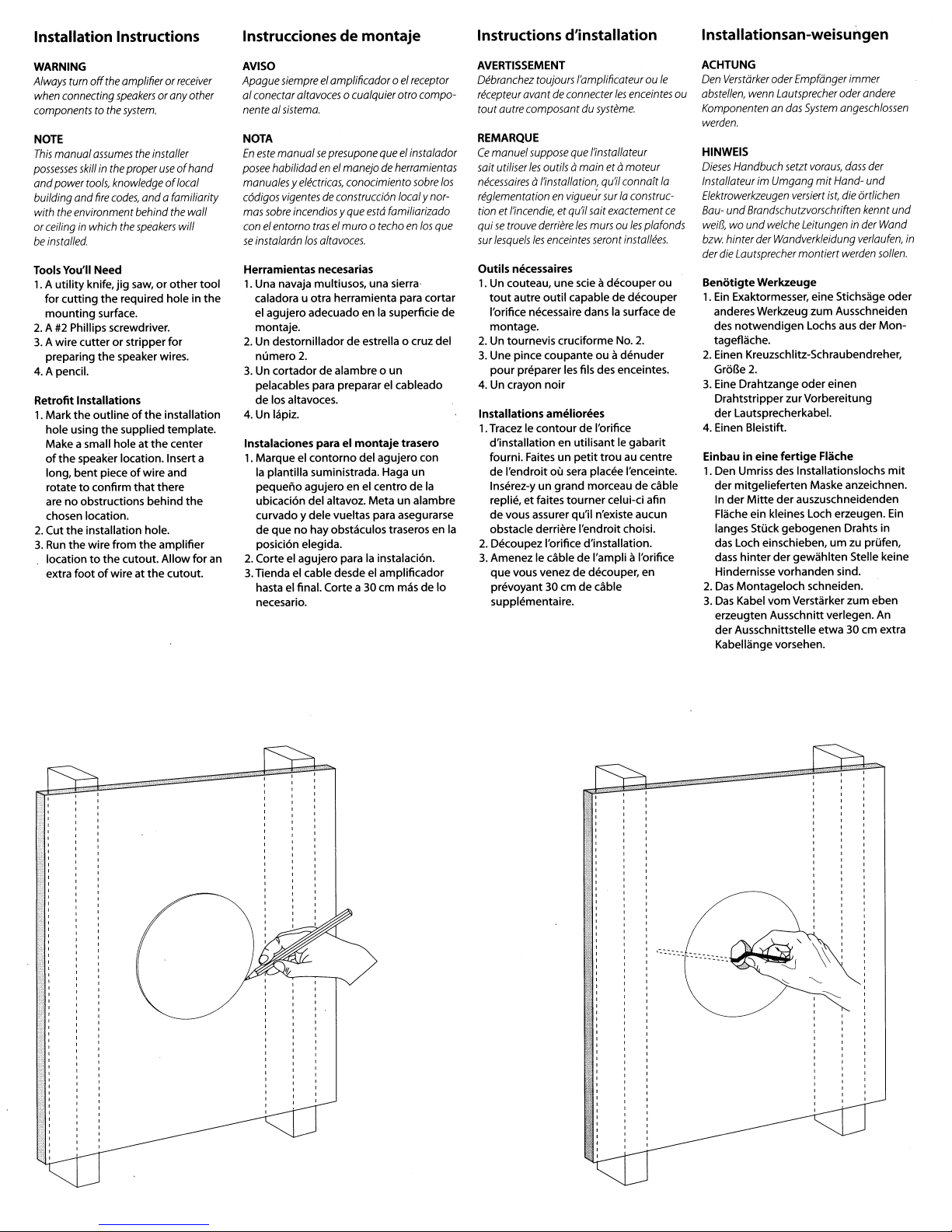
Retrofit Installations
1.
Mark
the
hole using
Make a small hole at
of
the
bent
long,
rotate
are no obstructions behind
chosen location.
2.
Cut
the
3.
Run
the
location
extra
footofwire at
amplifieror
speakers
system.
assumes
skillinthe
tools,
knife,
speaker location. Insert a
to
installation hole.
wire from
to
the
proper
knowledgeoflocal
fire
codes,
anda familiarity
the
speakers
jig
saw,orother
the
required hole in
surface.
the
speaker wires.
outlineofthe
the
supplied template.
pieceofwire and
confirm
that
the
the
cutout. Allowfor
the
receiver
oranyother
installer
useofhand
the
will
installation
the
center
there
the
amplifier
cutout.
wall
AVISO
Apague
siempreelamplificador0elreceptor
al conectar
altavoces
0 cualquier atro compo-
nentealsistema.
NOTA
En
este
manualsepresupone
posee
habilidadenel
manualesyeli?ctricas,
cMigos
vigentesdeconstrucci6n
mas
sobre
incendiosyque
conelentomo
se
instalardn
Herramientas necesarias
tool
1.
the
an
Una navaja multiusos, una sierra·
caladora u otra herramienta para cortar
el
agujero adecuado enlasuperficie de
montaje.
2.Undestornillador deestrella 0 cruz del
numero
3.
Un
cortador dealambre 0 un
pelacables para preparar el cableado
de los altavoces.
4.Unlapiz.
Instalaciones para
1.
Marqueelcontorno
la
plantilla suministrada. Haga
pequeno agujeroen el centro de
ubicacion del altavoz. Meta un alambre
curvado y delevueltas para asegurarse
de que no hayobstaculos traseros en
posicion elegida.
2.
Corteelagujero paralainstalacion.
3.
Tiendaelcable desdeel amplificador
el
final. Corte a30cm mas de
hasta
necesario.
manejodeherramientas
conocimiento
traselmuro 0
los
alta
voces.
2.
el
queelinstalador
sobre
localy
estd
familiarizado
techoenlos
montaje
trasero
del agujero con
un
la
nor-
que
10
AVERTISSEMENT
los
Oebranchez
recepteur
toutautre
REMARQUE
Ce
saitutiliser
necessaires
toujours
avantdeconnecter
compoSQntdusysteme.
manuel
suppose
les
outils amainet amoteur
a/'installation, qu'iIconnait
reglementationenvigueur
tion et
/'incendie,
quisetrouve
sur
lesquels
Outils necessaires
1. Un couteau, une scie II decouper
tout
I'orifice necessaire dans
montage.
2.
Un tournevis cruciforme No.2.
etqu'il sait exactement
derriere
les
enceintes
autre
outil
3. Une pince coupante
pour
preparer les fils des enceintes.
4.
Un crayon
Installations ameliorees
1.
Tracez Ie contourdeI'orifice
d'installation en utilisant
fourni. Faites un
de I'endroit
Inserez-y un grand morceau de cable
replie,
de
la
obstacle derriere I'endroitchoisi.
2.
Decoupez I'orifice d'installation.
3.
AmenezIecabledeI'ampliIII'orifice
que vous venez de decouper, en
prevoyant
supplementaire.
noir
OU
sera
et
faites
vous assurer qu'il n'existe aucun
tourner
30
cmdecable
I'amplificateurouIe
les
enceintes
que
/'installateur
la
surlaconstruc-
les
mursoules
seront
capable de decouper
ouIIdenuder
petit
placee I'enceinte.
pia
installees.
ou
la
surface de
Ie
gabarit
trou au centre
celui-ci afin
fonds
ACHTUNG
Den
ou
Verstarker
abstellen,
Komponentenandas
werden.
HINWEIS
Oieses
InstallateurimUmgang
Elektrowerkzeugen
ce
Bauweds,wound
bzw.
der
die
Benotigte
1.
Ein
anderes Werkzeug zum Ausschneiden
des
tageflache.
2.
Einen Kreuzschlitz-Schraubendreher,
GroBe
3.
Eine Drahtzange
Drahtstripperzur Vorbereitung
der
4.
Einen Bleistift.
Einbau
1.
Den Umriss des Installationslochs
der
In
Flache ein kleines Loch erzeugen.
langes Stuck gebogenen Drahts in
das Loch einschieben, urn zu prufen,
dass
Hindernisse vorhanden sind.
2.
Das
3.
Das
erzeugten Ausschnitt verlegen.
der
Kabellange vorsehen.
oder
Empfanger
wenn
Lautsprecher
Handbuch
setzt
versiert
und
Brandschurzvorschriften
welche
hinter
Lautsprecher
Exaktormesser, eine Stichsage oder
notwendigen
2.
Lautsprecherkabel.
in
eine
mitgelieferten Maske anzeichnen.
der
Mitte
hinter
Montageloch schneiden.
Kabel
Ausschnittstelle etwa30cm extra
Leitungeninder
der
Wandverkleidung
montierr
Werkzeuge
oder
fertige
der
auszuschneidenden
der
gewahlten Stelle keine
vom
Verstarker zum eben
System
voraus,
mit
Hand-
ist,
Lochs aus
einen
Flache
immer
oder
andere
angeschlossen
dass
der
und
die
6rtlichen
kennt
Wand
verlaufen,
werden
sollen.
der
Mon-
mit
Ein
An
und
in
Page 3

All Installations
1.
Strip V,-inch (13mm)ofinsulation
from
the
wire, and
strands together.The speaker jack
will accept eitherbare wire
14-gauge.
2.
Connect
3.
Slide
4.
TIghten
screws.The
pivot
the
the
speaker
the
into
speakertothe
Important:
Do notovertighten the
If
you
wishtopaint your
grilles,
itshouldbedone
installationofthe
Please
see thepaintinginstructions.
twist
the
wiretothe
4 Phillips
mounting
position andclamp
mounting
into
speaker.
the
cutout.
mounting
arms
surface.
screws.
speakers
prior
grille.
to
wire
up
will
or
to
the
Todas
las
instalaciones
1.
Pele13mm
tuerza
EI
conector del altavozacepta
alambredecalibre 14.
2.
Conecte el cablealaltavoz.
3.
Introduzca el altavozen el agujero.
4.
Apriete los tornillosdeestrella 0 cruz
montaje.
hasta
tavoz sujetoa
del aislante del cable y re-
el
extremo para agrupar los hilos.
Los
brazosdemontaje giraran
su
posici6n y mantendran el al-
la
superficie del montaje.
Importante:
No
apriete demasiado
5i
quiere
pintar
berG
hacerlo
Consulte
antesde10
las
instrucciones
los
altavoces0las
instalaci6nde10
los
tomil/os.
rejiilas
para
pintarlos.
tanto
Toutes installations
1.
Denudez13mmdecable,ettorsadez
les fils soupies ensemble.
I'enceinte accepte les cables denudes
d'un
diametre maximum decalibre
2.
Connectez Ie cable aI'enceinte.
3.lntroduisez I'enceintedans I'orifice
decoupe.
de
4.
Revissez
les
de-
rejilla.
ports defixation
et
fixent I'enceinte sur la surface de
fixation.
Important:
Ne
resserrez
5i
vous
grilles,
Veuillez
peinture quisuivent.
voulez
faites-Ie
consulter
pas
peindre
vis de fixation.
avant!'installation
pivotent
les
vis
excessivement.
les
enceintesoules
les
instructions de
La
fiche de
Les
sup-
en position
des
grilles.
Aile Installationen
1.13mm
14.
2.
3.
4.
Wichtig:
Die
Wenn
werden
Installation
(siehe
Isolierung
anteln, und dieDrahtlitzenzusammendrehen. DerLautsprecheranschluss
nimmt
entwederblanken Draht bis
AWG14.
Kabel an den Lautsprecher anschlieBen.
Den Lautsprecher in den Ausschnitt
schieben.
Die Kreuzschlitz-Befestigungs-schrauben festziehen. Die Montagearme
schwenken in die Einbaustellung und
klemmen den Lautsprecher an der
Montageflachefest.
vom
Schrauben nicht zu
die
Lautsprecher
soilen,
des
Anweisungen
muss
dies
Ziergitters
zum
oder
vor
Kabel
entm-
fest
anziehen.
Ziergitter lackiert
der
geschehen
Lackieren).
zu
S.
5.
Insert
the
grille
into
the
slots in
Frame
mask
light
with
buildup
the
paint
the
into
coats. If
a brush
the
baffle by
along
Painting
The speakers may be painted before
or
already primed.
1.
Insert
the
2.
Paint
spray paint,
you are applying paint
or
two
"runs"onthe
3.
finger pullstoremove
gently
the
afterthey are installed.Theyare
the
frameofthe
the
roller,
very
prevent excessive paint
After
the
mask.
applying pressure
edge.
The
Speaker
supplied
frame.Ifyou are using
thin
light
paint has dried,use
paint
speaker.
apply
two
the
paintand apply
coats.This helps
frame.
or
Insertelarejilla en
presionando ligeramenteen los extremos.
Todas
las
instalaciones
Pinturaelmarco del altavoz
Los
altavoces pueden pintarseantes
o despues
fabrica con can base para pintura
1.
2.
3.
delainstalaci6n.Vienen de
Insertelaplantilla (mascara) para pintar
suministrada en el marco del altavoz.
Pinte el marco.Siutiliza pintura en
spray, aplique doscapas Iigeras.
utiliza pincel 0 rodillo, diluyalapintura
y aplique doscapas
evitara
el
el
Una vez
lugares previstos en
para retirarla.
exceso de pintura y
"corrimiento"dela misma.
secalapintura, tiredelos
las
ranuras del bafle
muy
delgadas. Esto
la
mascara
0 primer.
Si
S.
Inserezlagrille dans les fentes
haut-parleuramembrane en appuyant legerementsur
Peinture
Les
ou apres leur installation. Elles
re~u
1.
InserezIemasque a peinturefourni
dans
2.
Peignez Ie coffret.Sivous utilisezdela
peintureaupistolet, appliquezdeux
couches legeres.
la
rouleau, diluez-Ia
couches tres lege
ainsi une accumulationexcessive de
peinture
3.
Une fois
utilisez les languettes
masque de peinture.
Coffrets
enceintes peuventetre peintes avant
une couche defond.
Ie
coffretdeI'enceinte.
peinture avec un pinceauouun
ou
quelapeinture est seche,
ses
des
Si
vous appliquez
et
appliquez deux
res.
Vous eviterez
des coulees sur Ie coffret.
bords.
enceintes
ont
pour
retirer
du
deja
5.
Fugen
Sie
das Ziergitter indie Schlitze
der
Schallwand ein, indem
in
lang der Kante vorsichtig andrucken.
Lackierung
Die Lautsprecher k6nnen vorodernach
Installation lackiertwerden.
mit
einerGrundierung versehen.
1.
Legen
Lackierungsmaske in den
Lautsprecherrahmen.
2.
Lackieren
Lack aufspruhen, mussen zwei dunne
Schichten aufgetragen werden.Wenn
Lack
aus
verdunnen
dann zwei ganz dunneSchichten auf.
Ie
Dies verhindert ubermaBigdicke
Lackansammlungen oder Lack-"Tranen"
auf
dem Rahmen.
3.
Nach
Sie
die Lackierungsmaskean den
Fingerlaschen
Lautsprecherrahmen
Sie
die mitgelieferte
Sie
den Rahmen.Wenn
mit
einem Pinsel oder einerWalze
der
Dose aufgetragen wird,
Sie
erst den Lack und tragen
dem
Trocknen des
abo
Sie
Lacks
Sie
ent-
der
sind bereits
Sie
den
ziehen
Page 4

Painting
1.
the
Carefully remove
the insideofthe
Speaker Grille
the
grille. Setitaside
in a clean location for later
reinstallation.
2.
Paint
the
grille.Ifyou are using
spray paint, apply
you are applying
or
roller,
thin
two
very
prevent paint
paint
the
paint and apply
light
coats.This helps
from
two
filling
on the grille.
3.
After
the
paintisdry, reinstall the
cloth and grillelogo.
cloth
light
with
from
the
coats.
a brush
holes
La
rejilla del altavoz
1.
Quitecuidadosamentelatela del
delarejilla. Dejela aparte en
interior
limpio
sitio
2.
Pinte la rejilla.Siutiliza pintura en spray,
parasuposterior instalacion.
apliquedoscapas ligeras.
If
0
un
pincel
rodillo, diluyalapintura y
aplique doscapas
Esto
evitara el excesodepintura y
el "corrimiento"
3.
Cuandolapintura este
colocar
la
tela y
delamisma.
ellogo.
muy
Si
utiliza
delgadas.
seca,
vue
Iva
PeintureGrilledesenceintes
1.
OtezIetissudej'interieurdela
Mettez-Ie
propre.
2.
Peignezlagrille.Sivous utilisez de
peinture au pistolet, appliquezdeux
couches legeres.
la
rouleau, diluez-Ia et appliquezdeux
couches tres lege
a
ainsi
trous
3.
Une fois
reinstallez
de
cote dans un endroit
peintureavecunpinceau ou un
quelapeinture neremplisse les
delagrille.
quelapeintureest seche,
Ie
tissuetIe
Si
vous appliquez
res.
Vous eviterez
logodela
grille.
grille.
Lackierung LautsprecherZiergitter
1.
Entfernen
der Innenseitedes Ziergitters. Legen
la
es
sauberen
2.
Lackieren
Lack aufsprUhen, mUssen zwei dUnne
Schichten aufgetragen werden.Wenn
Lack
aus
verdUnnen
dann zwei ganz dUnne Schichten auf.
Damit
Locher des Ziergitters
3.
Nachdem der Lacktrocken ist,
installieren
Ziergitter-Logo.
Sie
vorsichtig g}lsTuch von
zur spateren Installationan einem
Ort
abo
Sie
das Ziergitter.Wenn
mit
einem Pinsel oder einerWalze
der
Dose aufgetragen wird,
Sie
erst den Lack und tragen
wird
verhindert, dass sich die
Sie
dasTuch
mit
Lack fUlien.
und
das
Sie
Sie
den
ForEUCustomers
This symbolfound on
that
the
household waste.Instead,itmaybeplaced
in aseparate collection facility for electronic
wasteorreturnedtoa
retailer
The producer paidtorecycle this product.
Doing this contributes
minimizes adverse effects on
ment
and
for
incorrectdisposal.
If
Service
First, contact the dealer
product
when
purchasing similar
human
Seems
Only
mus
health
the
not
to
and avoids
product
indicates
be disposedofwith
product.
reuse
and
recycling.
the
environ-
any
nnes
Necessary
from
whom
you purchased the product.
Or contact us via e-mail at:
USA
and Canada:
support@bostona.com
Japan: ba_info@dm-holdings.com
Asia/Pacific countries:
service@dm-singapore.com
We
will
promptly
actiontotake. Ifitis
return your speakerstothe
please ship
been repaired,
advise youofwhat
necessary
it
prepaid. Afterithas
we
will return
to
factory,
it
freight prepaid in the United States
and Canada,
S610
para c1ientesdela
Este simbolo
indica
que
este
la
basuradomestica.Envezdeesto,
colocarse enunpuntaderecogida separada
para desechos electr6nicos 0 devuelto a un
detallista al
El
producto.
Iizar y reciclar,
sobreel
y evita
incorrecta.
Si
comprarunproducto
fabricante ha
Haciendo esto
medioambiente
cualquier
cree que necesita
que
apareceenel
no
debe
pagado
minimiza
multa
UE
produeto
ser
eliminado
con
debe
si-milar.
para reciclareste
contribuyeareuti-
los efectosadversos
y la salud
humana
por
una
eliminacion
asistencia tecnica
Prlmero, pongase en contacto con el distribuidoralcualhacomprado el producto.
opongaseen contacto con nosotros
mediodeun
Estados
support@bostona.com
Japon: ba_info@dm-holdings.com
Asia/paises
service@dm-singapore.com
Le
indicaremosdeinmediato
tomar.
la
fabrica,Ierogamos
a
con franqueo prepago. Despues de
reparacion,10devolveremos con costas
de
transporte pagados solo en Estados
Unidos yCanada.
correo electronico:
Unidos
y Canada:
del
Pacifi co:
Siesnecesario devolverunaltavoz
que10envie
que
por
accion
la
Pour les clientsdeI'UE
Ce
symbole
produitnedoit
domestiques.
une
installationdecollecte separee destinee
aux dechets
detaillant
lorsque
semblable.Lefabricant a-paye
ce
produit,cequi
recycleretce
I'environnementetla santehumaine,
sur
en
evitant
des
d'elimination
uniquement
sur Ie
produit
indique
pas etre
jete
II
doit
plutot
electroniques
qui
amendes
incorrecte.
ou
vous achetezunproduit
contribue
minimise
encouruesencas
que
Ie
avec les dechets
etre placedans
remis a
un
pour
recycler
areutiliser
les effetsnefastes
et
tout
Demandedeservice
apres-vente
Veuillez contacteren premierlieuIerevendeuraupres
ce
produit.
Ou veuillez nous contacter par
Etats-UnisetCanada:
support@bostona.com
Japon : ba_info@dm-holdings.com
Paysdel'Asie/Pacifi
service@dm-singapore.com
Nous vous informerons rapidement
des mesures
retourner
veuillez I'expedierdans
Apres
en fret prepaye aux Etats-Unis
Canada.
duquel
vous avez achete
que:
aprendre.
Si
vous devez
aI'usine votre haut-parleur
un
la
reparation,IIvous
colis prepaye.
sera
e-mail:
retourne
et
au
NurfOr
Kunden in
der
Dieses
auf
weist
darauf
dem
HausmOli
bei einerSammelstelle
abgegeben
werden,
wenn
ben
wird. DerHersteller hat
dieses Produktes bezahlt. Dies
Wiederverwertung
minimiert
schadliche
Umwelt
und
und
vermeidet
gemasse Entsorgung.
EU
dem
Produkt angebrachte Symbol
hin, dass das
oder
die menschliche Gesundheit
Produkt
entsorgt
dem
Handler
ein
ahnliches
und
Auswirkungen
Geldbussen fUrunsach-
nicht
werden darf.Esmuss
fOr
Elektronikschrolt
Obergeben
Produkt
fOr
das Recycling
tragt
zurn Recycling
erwor-
zur
auf
mit
bei
die
Falls ein Kundendienst
notwendig
Nehmen
Handlerauf, bei
gekauft haben.
Oderkontaktieren
und
USA
Japan: ba_info@dm-holdings.com
Asien/Pazifi sche Region:
service@dm-singapore.com
Wir werden Ihnen
Sie
wie
notwendig
HerstellerzurUckzusenden,
Sie
diese
werden
in Kanada ebenfalls frei zurUcksenden.
scheint
Sie
zunachst Kontakt
dem
Sie
Sie
Kanada: support@bostona.com
umgehend
weiter vorgehen sollten.
sein sollte, Lautsprecher den
bitte
frei. Nach
wir
Siein den
mit
dem
das Produkt
uns perE-Mail unter:
mitteilen,
Falls
so
versenden
der
Reparatur
USA
und
es
300 Jubilee Drive, Peabody,
bostonacoustics.com
© 2008Boston Acoustics, Inc.Boston, Boston Acoustics,
symbol isa trademad<
DTSisa registered trademarksofDTS,
of
Boston Acoustics, Inc.
Dolby
Inc. Specifications are subjecttochange
MA
and
Digital,
01960
the
Boston Acoustics
and
Dolby
USA
logo
Pro Logic are registered trademarksofDolby
are registered trademarks
without
notice. 142-003535-1
and
the
BfA ellipse
Laboratories.
Page 5

Page 6

Page 7

l
...
Boston
acoustics'
AnN:
PRODUCT REGISTRATION
BOSTON ACOUSTICS INC
300 JUBILEE DR
PEABODY MA 01960-4030
111"""111,1",11"11""1"111,,,,,11,11,,,11,,,11,"1,,,11
Postage
Required
Post Office will
notdeliver
without
proper
postage.
Page 8

~
Boston
Acoustics·
Product Registration
for
U.S.
and Canada purchases only.
Boston
Thank
you
for
purchasingaBoston
Acoustics product
Your
feedbackwmhelpusto
conUnue
providing
acoustic
6-
consumers
with
!he
best
possible products and service. Data provIded Is the confidential
property
of
Boston
AcoustIcs,
Inc. and Is
not
distributedorsoldtothird
partltlS.
Please print below, or register your new product online at: bostonacoustics,comlprodreg
First
Name
_
last
Name
_
StreetAddress _
Apl.._-----
City _
State _
ZIP
_
e·mall
_
Ph008
_
Age
Group:
UndElf
20
201029
30 to 39 40 to 49 50 to 59
60
to 69
70to79
80
and
over
Marttal
Status;
Single
_
Marrled_
Mate
Female
Educatloo:
High School _
Some
College _ Associate/Jr. College Degree _ 4-Year College Degree _ Graduate
School_
What type of Boston AcotJstics product did you ptJrt:hase? Home StereolThealBf
In-WaIUln-eelling _
MulUmedlalPC
DateofPurchase
,
,,
_
Model
Name
serial
#
1I;;;;;;;;;';~~.~.;;
••
;;_;;;;~~h;;;.;;;;;'
••;,;;,;,";'"
------
HO'N
did
you
hear aboutlhts
product?
Store Name City State _
Boston Acoustics advertisement Store salesperson _ Store advertisement Magazlne review _
Store
display_
Online review _ Tntde show_
PC
manufacturer _
Friendlfamity_
Q1he,----------------------------
What other brand(s) and model(s)
did
yoo
consider
when
maklng lhls purchase?
Bnlnd(s) _
Model(a) _
Thank you
for
completing this form.Ifyou have any tec:hnlc.l question.
or
.t.
Interested In other Boston Acoustlca products, vlalt ua on the
Webatboatonacouatlca,com.orcall (978) 538-5000.
m007
&a.lon
AeouIIlclI,
Ir'lt.
All
RIghts
R~
142.oo1eol-3
 Loading...