

Boston Classic CS 2310 Owner's Manual
OWNER’S MANUAL / SAFETY INSTRUCTIONS / COMPLIANCE INFORMATION
Classic CS 2310
5.1 Surround Speaker System
Español
5.1 Sistema de parlantes
de sonido envolvente
Manual del Propietario /
Instrucciones de Seguridad /
Información de Cumplimiento
Français
Système de haut-parleur
Surround 5.1
Guide de l’utilisateur /
Instructions de sécurité /
Informations relatives à la
conformité
Italiano
5.1 Sistema di
altoparlanti surround
Manuale dell’utente/
Istruzioni di sicurezza/
Informazioni sulla conformità
Svenska
5.1 Surroundhögtalarsystem
Bruksanvisning /
säkerhetsanvisningar /
information om
överensstämmelse
Deutsch
5.1-SurroundLautsprechersystem
Bedienungsanleitung /
Sicherheitshinweise /
Konformitätserklärung

N
G
H
E
L
I
IMPORTANT SAFETY INSTRUCTIONS
S
This symbol found on the apparatus indicates hazards
arising from dangerous voltages.
WARNING! To reduce the risk of fire or electrical shock,
do not expose this apparatus to rain or moisture
.
This symbol found on the apparatus indicates the user
should read all safety statements found in the user
manual.
This symbol found on the apparatus indicates double
insulation.
1. Read these instructions.
2. Keep these instructions.
3. Heed all warnings.
4. Follow all instructions.
5. Do not use this apparatus near water.
6. Clean only with dry cloth.
7. Do not block any ventilation openings. Install in accordance
with the manufacturer’s instructions.
8. Do not install near any heat sources such as radiators, heat
registers, stoves, or other apparatus (including amplifiers) that
produce heat.
9. Do not defeat the safety purpose of the polarized or grounding
type plug. A polarized plug has two blades with one wider
than the other. A grounding-type plug has two blades and
a third grounding prong. The wide blade or the third prong
is provided for your safety. If the provided plug does not fit
into your outlet, consult an electrician for replacement of the
obsolete outlet.
10. Protect the power cord from being walked on or pinched
particularly at plugs, convenience receptacles, and the point
where they exit from the apparatus.
11. Only use attachments/accessories specified by the
manufacturer.
12. Unplug this apparatus during lightning storms or when
unused for long periods of time.
This symbol found on the apparatus indicates that
the apparatus must be placed in a separate collection
facility for electronic waste and not disposed with
household waste.
13. Refer all servicing to qualified service personnel. Servicing is
required when the apparatus has been damaged in any way,
such as power-supply cord or plug is damaged, liquid has
been spilled or objects have fallen into the apparatus, the
apparatus has been exposed to rain or moisture, does not
operate normally, or has been dropped.
14. Maintain a minimum distance of 2” (50mm) around the front,
rear, and sides of the apparatus for sufficient ventilation. The
ventilation should not be impeded by covering the ventilation
openings or placing on or around the apparatus items such as
newspapers, table-cloths, curtains, etc.
15. No open flame sources, such as lighted candles, should be
placed on the apparatus.
16. The apparatus shall not be exposed to dripping or splashing.
No objects filled with liquids, such as vases, shall be placed on
the apparatus.
17. Either the power inlet connector on the rear of the apparatus
or the power plug at the wall must remain accessible, to be
able to disconnect power from the apparatus.
18. To completely disconnect this apparatus from the AC
Mains, disconnect the power supply cord plug from the AC
receptacle.
19. The mains plug of the power supply cord shall remain readily
operable.
2

Specifications CS 23 CS 223C CS Sub 10
Frequency Response: 120Hz – 20kHz 100Hz – 20kHz 32 - 150Hz
Recommended Amplier 10 – 150 watts 15 – 150 watts —
Power Range:
Sensitivity: 89dB [SPL/2.8v at 1m] 89dB [SPL/2.8v at 1m] —
Nominal Impedance: 8 ohms 8 ohms —
Crossover Frequency: 2,700Hz 2,700Hz 40Hz - 180Hz 24dB/octave
lowpass
Amplier Output: — — 100 watts RMS; BassTrac®
circuitry eliminates distortion
Woofer: 31/2” (89mm) Dual 31/2” (89mm) 10” (254mm) DCD
copolymer DCD with copolymer DCD with
Phase Plugs and Phase Plugs and
MagnaGuard® MagnaGuard
E
N
G
L
I
S
H
Tweeter: 1” (25mm) Kortec® 1” (25mm) Kortec —
Soft Dome Soft Dome
Dimensions: (H x W x D) 711⁄16 x 5 x 415⁄16” 51⁄2 x 121⁄2 x 47⁄16” 15 x 15 x 15”
(195 x 127 x 124mm) (141 x 318 x 112mm) (381 x 381 x 381mm)
Weight: 4 lbs (1.8kg) 7 lbs (3.2kg) 32 lbs (14.5kg)
.
CS 2310 Introduction
Thank you for purchasing a Boston Acoustics Multi-Channel Speaker System. These speakers incorporate high-quality
components that produce the famous Boston sound. The CS 2310 is ideally suited for use as a 5.1 channel solution in a highquality home theater or music system. The CS 2310 is complete with everything you need for the typical speaker system
including speaker wire, satellite speakers, center channel, and a subwoofer.
The CS 2310 speaker system delivers exceptionally articulate on-screen dialog, music, effects, and room filling bass from a
small, sleek package. Compact driver placement and quality, system-specific crossovers assure a wide uniform dispersion
for complete coverage of a listening room. All speakers also feature MagnaGuard® magnetic shielding which ensures the
speaker’s magnetic field does not interfere with the televisions picture.
3
N
G
H
E
L
I
S
Unpacking the System
Carefully unpack the system. If there is any sign of damage from transit, report it immediately to your dealer and/or delivery
service. Keep the shipping carton and packing materials for future use.
Placement Options
The CS 2310 speakers can easily be placed upon a tabletop or wall-mounted. The center channel and satellite speakers are
designed to easily mount on the wall using the keyhole slot(s) on the back of the speaker. When mounting the speakers to
the wall, use the supplied rubber bumpers.
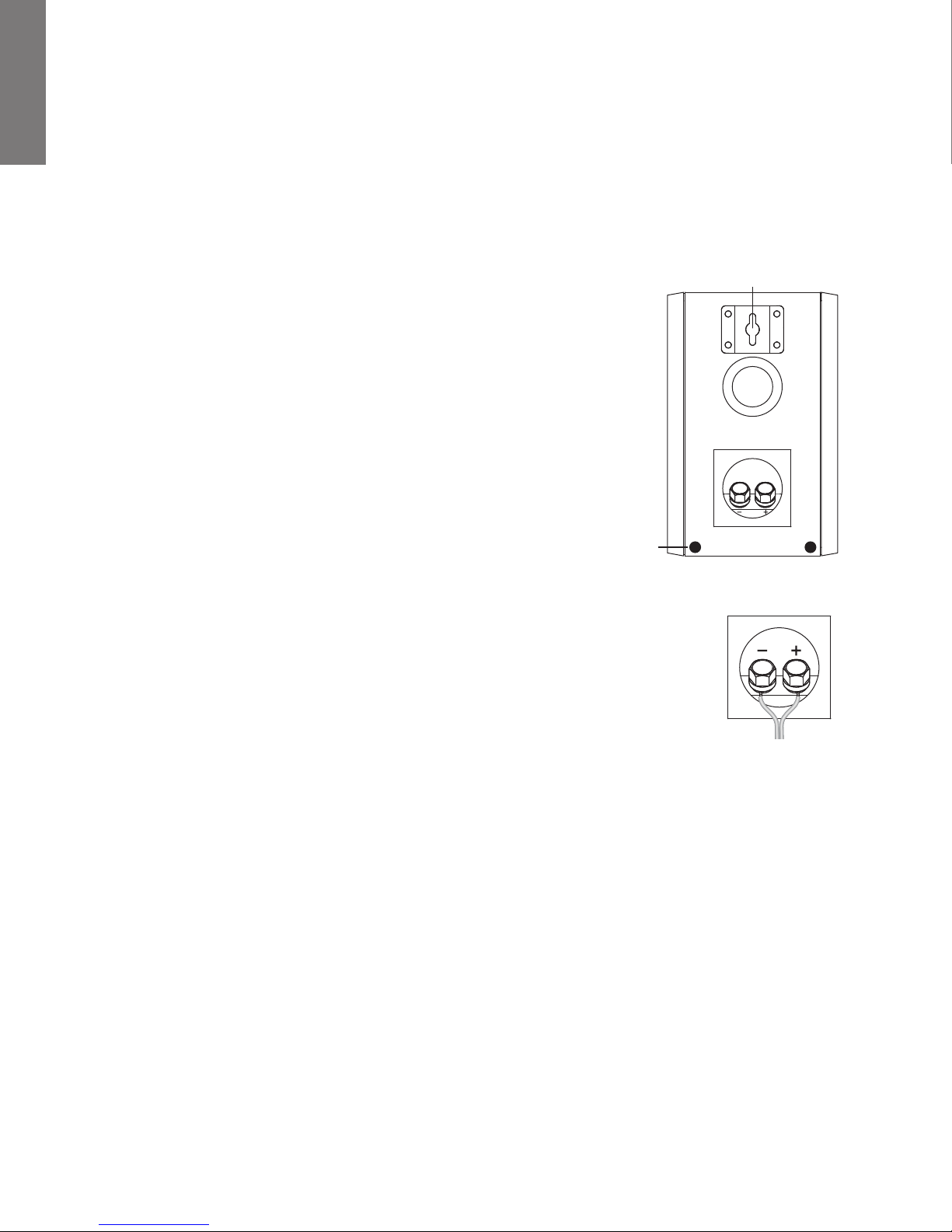
The keyhole mounting option is similar to hanging a picture frame on a wall. Install a
#8 screw (not included) into the sheetrock, making sure to go into a stud, and hang
the speaker onto the screw head. If a stud is not available, a sheetrock anchor should
be used to support the weight of the speaker. It is advisable to connect the speaker
wire prior to wall-mounting.
NOTE: Because there are so many different kinds of surfaces on which the speakers
could be mounted. There is no one type of fastener that we could supply that would
work in all the possible situations. So taking into account the surface the speaker is
being mounted on, acquire the appropriate type of fasteners. If you’re not sure what
type of fastener to use, take the mounting bracket to a friendly hardware store, tell
them about the wall you’re mounting the speaker on, and ask them to recommend
an appropriate fastener. Keep in mind the weight of the speaker.
Rubber
Bumper
Speaker Connections
After your speakers are properly placed, you are ready to wire your system. First, turn off all system
power. Use the speaker wire included with the system to make your connections. Please see the
illustration for guidance connecting the wires to the satellites and center channel.
Important!
To ensure the best performance observe polarities when making speaker connections, as shown in
the illustration. Connect each + terminal on the back of the amplifier or receiver to the respective +
(red) terminal on each speaker. Connect the – (black) terminals in the same way. If the connections
are not made correctly it can cause poor bass response and imaging. Also, to avoid short circuits
that may damage your equipment be careful not to let any of the bare wires touch each other.
Keyhole Mount
Be sure to maintain
proper + and – polarity
at all speaker wire
connections.
Subwoofer Connections
NOTE: Power is always supplied to the subwoofer electronics unless it is unplugged or switched to the o position using the
power switch located on the rear panel. The auto-on circuitry only activates or deactivates the power amplifier. Make sure
your subwoofer and receiver are unplugged when making the connection.
Power: When plugging your subwoofer in be sure to use a wall outlet, or dedicated electrical outlet. Some receivers will
provide a switched outlet. Do not use this. These on board electrical outlets do not offer the amount of current or proper
isolation required by a power amplifier, such as the one in your amplifier.
4

Line level or LFE: On most systems use the line level in or the LFE input. These inputs accept the line-level signal from your
receiver’s subwoofer output. Your receiver’s manual should indicate which input is most appropriate.
Turn off all power. Use the subwoofer cable included with your system to connect the subwoofer to your receiver’s
Subwoofer or LFE output. Connect the other end to the “Line In” on the back of the Subwoofer.
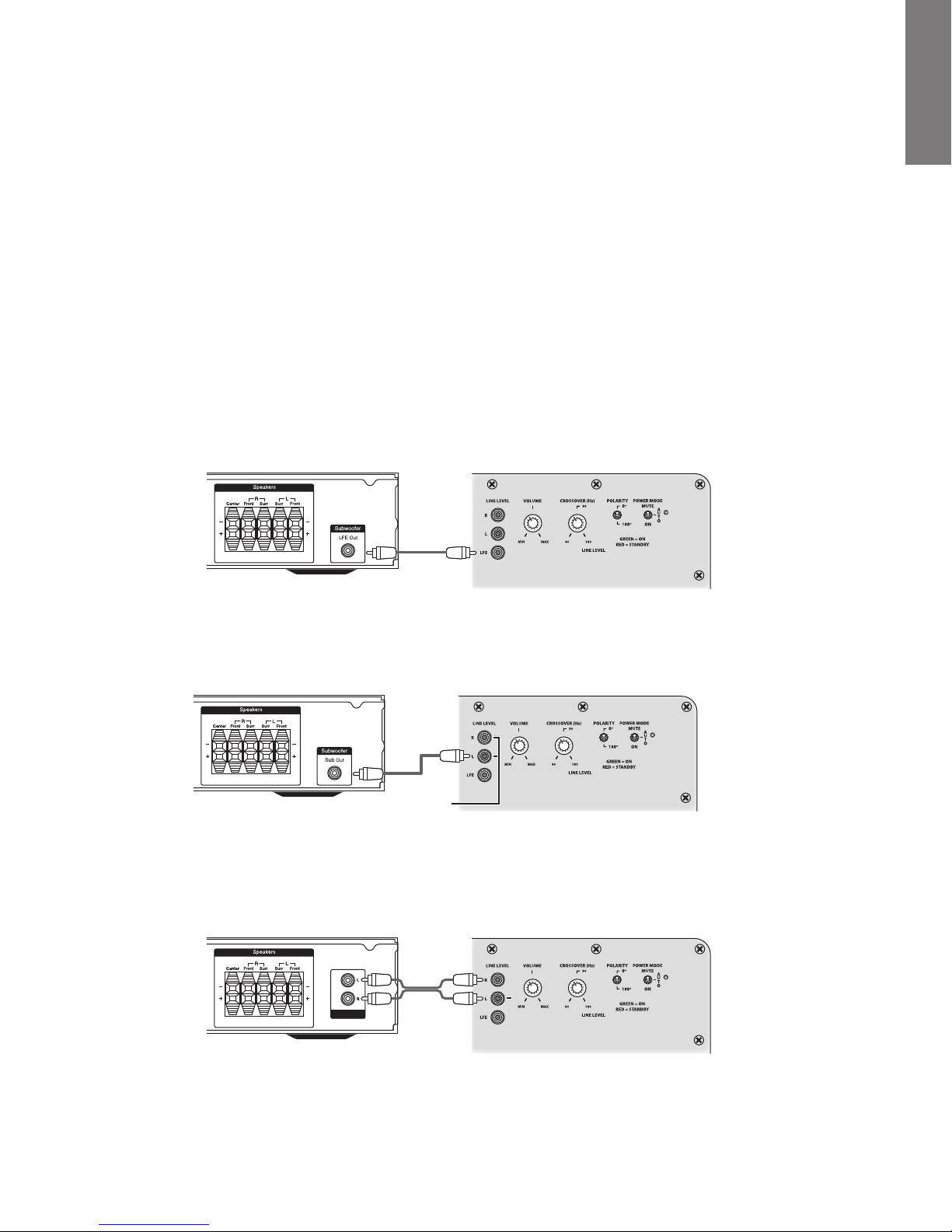
Connecting the Subwoofer to Digital Home Theater Systems Using LFE
Digital 5.1, 6.1 and 7.1 home theater electronics dedicate one channel (the “.1”) to reproduce the special low-frequency (LFE)
information (such as explosions and thunder) contained in digitally-encoded soundtracks.
Select ”subwoofer-yes” from your receiver’s set-up menu. Hooked up this way, the receiver’s amplifier is relieved of having
to reproduce the difficult low bass signals that can drive the receiver into audible distortion. In some cases, it can also depend
on several other settings within a receiver. We recommend consulting your receiver manual for further assistance in this area.
Use the subwoofer cable, as shown, to connect your digital receiver’s LFE subwoofer output to the subwoofer. Connect the
other end to the LFE input.
digital receiver CS Sub10 Amplier
.
E
N
G
L
I
S
H
Connecting the Subwoofer to Stereo or Dolby® Pro Logic®
For stereo or Dolby Pro Logic systems use the “sub out” connection from your receiver to the input on the subwoofer marked
“Left” and “Right”.
receiver CS Sub10 Amplier
use either input
Connecting to Electronics Without a Subwoofer Output
If the electronic in your system does not have a subwoofer of LFE output you can connect the CS Sub 10 to a preamp output.
Use a stereo RCA cable (not included) to connect the preamp outputs to the Left and Right Line Level inputs.
receiver CS Sub10 Amplier
Preamp Out
5

N
G
H
E
L
I
S
Adjusting the Crossover Control
When using the Line Level inputs (not the LFE input) the subwoofer’s built-in crossover is engaged. As a starting point, set the
crossover control on the subwoofer about 10Hz higher than the lower limit of your main speakers’ bass response. Fine -tune
the crossover setting by ear for the smoothest blend with your main speakers. The best setting of the crossover control will
depend on speaker placement and personal preference.
Operation
Power On/Auto/Standby
Plug the subwoofer’s AC cord into a wall outlet. Do not use the outlets on the back of the receiver. Set the power switch to
the desired setting.
OFF – The subwoofer is off and will not produce any sound. You may want to turn your subwoofer off if you will not be using
it for some time or wish to conserve electricity.
AUTO – The subwoofer will power on whenever a signal is detected. If no signal is detected after several minutes, it will
automatically enter the Standby mode.
ON – The subwoofer is always on.
An LED indicator between the Power switch and the Polarity switch indicates what mode the subwoofer is in.
OFF – The subwoofer is off
RED – STANDBY (No signal detected, Amp Off )
GREEN – ON (Signal detected, Amp On)
The subwoofer will automatically enter the Standby mode after several minutes when no signal is detected from your system.
The subwoofer will then power ON instantly when a signal is detected.
Crossover Control
Adjusts the frequency of the low pass filter for the subwoofer. Note: This control is not active when using the LFE input jack.
Volume Control
Turn the subwoofer Volume control to the 11 o’clock position. If no sound emanates from the subwoofer, check the AC-
line cord, Power switch, and input cables. (Are the connectors on the cables making proper contact? Is the AC-line cord
connected to a “live” receptacle, is the subwoofer in either the Auto or On position?)
Adjust the subwoofer Volume control until you hear a match between the main speaker and subwoofer. Bass response should
not overpower the room but rather be adjusted so there is a natural blend across the entire musical range.
Polarity Control
(0° or 180°): Selects regular (0°) or inverted (180°) phase for the subwoofer. Set this switch to provide the fullest, most
dynamic bass. The effect of phase will be most audible on low-frequency percussion instruments or music with a
continuously repeating bass line.
6

Maintenance and Service
All wiring connections should be inspected and cleaned or remade at least once a year.
If a problem does occur, make sure that all connections are properly made, secure and clean. If a problem occurs in one
loudspeaker, rewire that speaker in a different location within the system. Should the problem persist in this speaker the
problem is within the speaker. If the speaker sounds fine in the new position it is a strong indication of a more in depth issue
with the electronics in the system. In the event that your CS 2310 ever needs service, contact your local Boston Acoustics
dealer or visit bostona.com for a list of dealers in your area.
If your subwoofer does not play, check that all the connectors on the cables are making proper contact and that the AC plug
connected to a “live” receptacle.
Limited Warranty
Boston Acoustics warrants to the original purchaser of our CS 2310 system that it will be free of defects in materials and
workmanship in its mechanical parts for a period of 5 years from the date of purchase. The warranty period for the electrical
components of CS 2310 is 1 year.
Your responsibilities are to install and use them according to the instructions supplied, to provide safe and secure transportation
to an authorized Boston Acoustics service representative, and to present proof of purchase in the form of your sales slip when
requesting service.
E
N
G
L
I
S
H
Excluded from this warranty is damage that results from abuse, misuse, improper installation, accidents, shipping, or repairs/
modifications by anyone other than an authorized Boston Acoustics service representative.
This warranty is limited to the Boston Acoustics product and does not cover damage to any associated equipment. This
warranty does not cover the cost of removal or reinstallation. This warranty is void if the serial number has been removed or
defaced. This warranty gives you specific legal rights, and you may also have other rights which vary from state to state.
If Service Seems Necessary
First, contact the dealer from whom you purchased the product. If that is not possible, write to:
Boston Acoustics, Inc.
300 Jubilee Drive
Peabody, MA 01960 USA
Or contact us via e-mail at:
US: support@bostona.com
Japan: ba_info@dm-holdings.com
Asia Pacific: service@dm-singapore.com
We will promptly advise you of what action to take. If it is necessary to return your CS 2310 to the factory, please ship it
prepaid. After it has been repaired, we will return it freight prepaid in the United States and Canada.
Boston Acoustics continually strives to update and improve its products. The specifications and construction details are
subject to change without notice.
7
P
A
Ñ
O
E
S
INSTRUCCIONES DE SEGURIDAD IMPORTANTES
L
Este símbolo que aparece en el aparato indica peligros
derivados de tensiones peligrosas.
Este símbolo que aparece en el aparato indica que el
usuario debe leer todos los avisos de seguridad del
manual del usuario.
Este símbolo que aparece en el aparato indica doble
aislamiento.
ADVERTENCIA! Para reducir el riesgo de incendio o
descarga eléctrica, no exponga el aparato a la lluvia o a
la humedad
Este símbolo que aparece en el aparato indica que el
aparato se debe colocar en un punto de recolección
separada para desechos electrónicos y no debe ser
arrojado junto con los residuos domésticos.
.
1. Lea estas instrucciones.
2. Guarde estas instrucciones.
3. Preste atención a todas las advertencias.
4. Siga todas las instrucciones.
5. No use este aparato cerca de agua.
6. Limpie únicamente con una tela seca.
7. No obstruya las aberturas para ventilación. Instale de
acuerdo con las instrucciones del fabricante.
8. No instale cerca de fuentes de calor como radiadores,
rejillas de calefacción, estufas u otros aparatos (incluidos
amplificadores) que emitan calor.
9. No anule el propósito de seguridad del enchufe polarizado
o de puesta a tierra. Un enchufe polarizado tiene dos patas,
una más ancha que la otra. Un enchufe de puesta a tierra
tiene dos patas y una tercera de puesta a tierra. La pata
ancha o la tercera pata es para su seguridad. Si el enchufe
provisto no encaja en el toma, consulte a un electricista
para reemplazar el toma obsoleto.
10. Proteja el cable de alimentación para que no se pise ni se
apriete, especialmente en los enchufes, en los receptáculos,
y en el punto donde salen del aparato.
11. Utilice únicamente aditamentos o accesorios especificados
por el fabricante.
12. Desenchufe el aparato durante tormentas eléctricas o
cuando no se lo utilice durante períodos largos.
13. Todas las actividades de asistencia técnica deben ser
realizadas por personal de servicio calificado. Se requiere
asistencia técnica cuando el aparato se ha dañado de
cualquier manera, por ejemplo por daño del cable de
alimentación o del enchufe, derrame de un líquido o caída
de objetos en el aparato, exposición del aparato a lluvia o
humedad, o mal funcionamiento o caída del aparato.
14. Mantenga una distancia mínima de 2” (50mm) en el frente,
la parte posterior y los lados del aparato, para que reciba
suficiente ventilación. La ventilación no debe ser impedida
cubriendo las aberturas para ventilación ni colocando
sobre o alrededor del aparato elementos como periódicos,
manteles, cortinas, etc.
15. No se deben colocar fuentes de llama abierta, como velas
encendidas, sobre el aparato.
16. El aparato no se debe exponer a goteos ni salpicaduras. No
se deben colocar objetos llenos de líquido, como floreros,
sobre el aparato.
17. Ya sea el conector de entrada de potencia en la parte
posterior del aparato o el enchufe de la pared debe
permanecer accesible, para poder desconectar la potencia
del aparato.
18. Para desconectar el aparato por completo de la red de AC,
desconecte el cable de alimentación del receptáculo de AC.
19. El enchufe del cable de alimentación debe permanecer listo
para funcionar.
8

Especificaciones CS 23 CS 223C CS Sub 10
Respuesta de frecuencia: 120Hz – 20kHz 100Hz – 20kHz 32 - 150Hz
Rango de potencia de 10 – 150 vatios 15 – 150 vatios —
amplicador recomendado:
Sensibilidad: 89dB [SPL/2,8v a1m] 89dB [SPL/2,8v a1m] —
Impedancia Nominal: 8 ohms 8 ohms —
Frecuencia de transición: 2.700Hz 2.700Hz 40Hz - 180Hz 24dB/octava
pasa bajo
Salida del amplicador: — — 100 vatios RMS; BassTrac® los
circuitos eliminan la distorsión
Bae de bajos: 31/2” (89mm) Doble 31/2” (89mm) 10” (254mm) DCD
DCD copolímeros con DCD copolímeros con
Enchufes de fase y Enchufes de fase y
MagnaGuard® MagnaGuard
E
S
P
A
Ñ
O
L
Bae de agudos: 1” (25mm) Kortec® 1” (25mm) Kortec —
de cúpula flexible de cúpula flexible
Dimensiones: 711⁄16 x 5 x 415⁄16” 51⁄2 x 121⁄2 x 47⁄16” 15 x 15 x 15”
(Alto x Ancho x Profundidad) (195 x 127 x 124mm) (141 x 318 x 112mm) (381 x 381 x 381mm)
Peso: 4 libras (1,8 kg) 7 lbs (3,2 kg) 32 libras (14,5kg)
.
Introducción al CS 2310
Gracias por comprar el Sistema de parlantes de canales múltiples de Boston Acoustics. Estos parlantes incorporan
componentes de alta calidad que producen el sonido famoso de Boston. El sistema CS 2310 está idealmente diseñado para
usar como una solución de canal 5.1 en un sistema de cine en casa de alta calidad de canal 5.1 o un sistema de música. El
sistema CS 2310 está provisto de todo lo que necesita para el sistema de parlantes típico que incluye un cable de parlante,
parlantes satélite, canal central y un subwoofer.
El sistema CS 2310 de parlantes ofrece, articulados excepcionalmente, un diálogo en pantalla, música, efectos y bajos de
ambiente desde un paquete pequeño y elegante. La ubicación y calidad de la compactera, las frecuencias específicas del
sistema aseguran una dispersión uniforme amplia para cubrir por completo una sala de audiciones. Todos los parlantes
también presentan blindaje magnético MagnaGuard® que garantiza que el campo magnético del parlante no interfiera con la
imagen televisiva.
9
P
A
Ñ
O
E
S
Desembalaje del sistema
Desembale cuidadosamente el sistema. Si hay alguna señal de daños debidos al transporte, comuníqueselo inmediatamente
L
a su distribuidor y/o a su servicio de entrega. Conserve el cartón de envío y los materiales de embalaje para una futura
utilización.
Opciones de colocación
Los parlantes CS 2310 pueden colocarse fácilmente sobre un tablero de mesa o bien se instalan en la pared. El canal central
y los parlantes satélite están diseñados para instalar fácilmente en la pared con la(s) ranura(s) del orificio en la parte posterior
del parlante. Cuando instale los parlantes en la pared, utilice los paragolpes de goma suministrados.
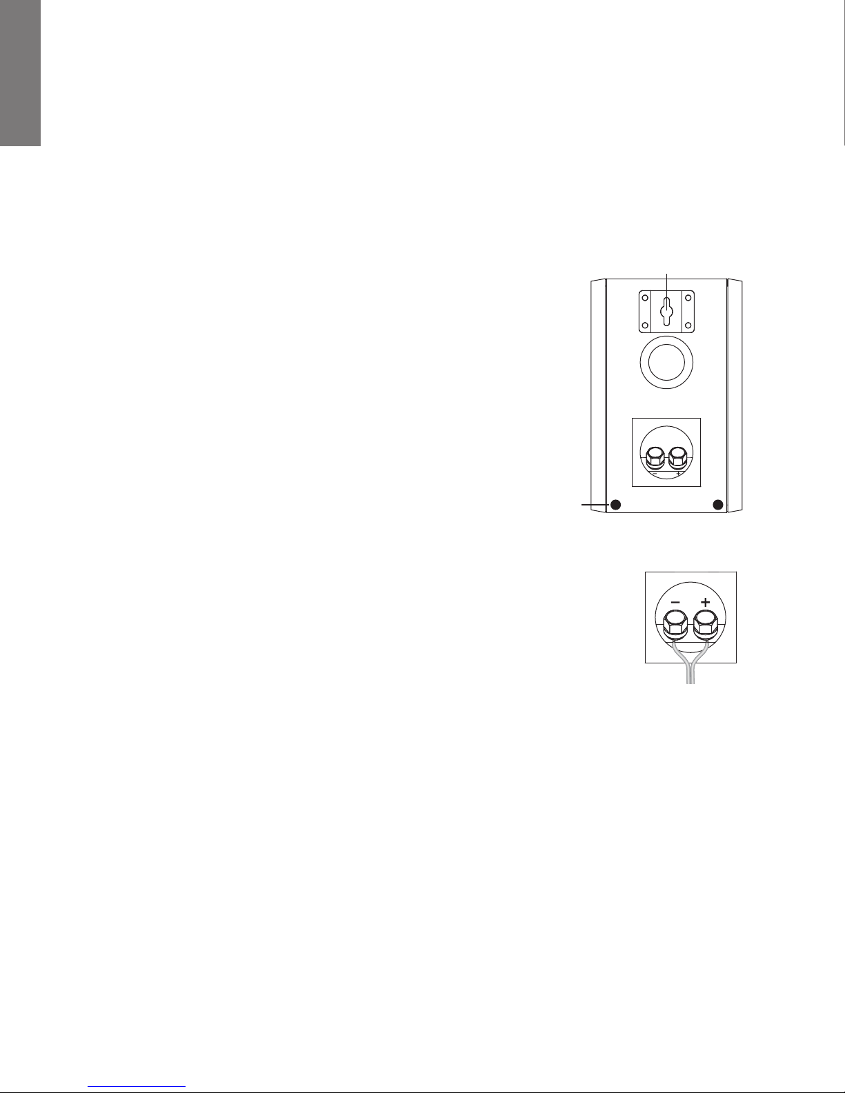
La opción de instalación en orificio es similar a colgar un cuadro en la pared. Instale
un tornillo #8 (no se incluye) dentro de la placa de yeso, asegurándose de que entre
en una tachuela, y cuelgue el parlante en la cabeza del tornillo. Si no se encuentra
disponible una tachuela, se debe usar un sostén de placa de yeso para sostener el
peso del parlante. Se recomienda conectar el cable del parlante antes de instalarlo
en la pared.
NOTA: Hay muchos tipos de superficies diferentes en los que los parlantes pueden
instalarse. No existe un tipo de sujetador que podamos suministrar que funcionaría
en todas las situaciones posibles. Por lo tanto, se debe tener en cuenta la superficie
en la que se instalará el parlante para adquirir el tipo apropiado de sujetadores. Si
no está seguro de qué tipo de sujetador utilizar, lleve el soporte para instalación
a una tienda de elementos de montaje que usted conozca y cuénteles acerca de
la pared en la que instalará el parlante. Pídales que le recomienden un sujetador
adecuado. Tenga en cuenta el peso del parlante.
Paragolpes
de goma
Conexiones del parlante
Una vez que sus parlantes estén debidamente colocados, ya puede conectar el sistema. En primer
lugar, apague la potencia del sistema. Use el cable del parlante incluido en el sistema para realizar
sus conexiones. Por favor, observe la ilustración para guiarse en la conexión de cables a los satélites
y al canal central.
¡Importante!
Para garantizar el mejor rendimiento, observe las polaridades cuando realice las conexiones del
parlante, tal como se muestra en la ilustración. Conecte cada terminal + de la parte trasera del
amplificador o receptor al respectivo terminal + (rojo) de cada parlante. Conecte los terminales –
(negros) de la misma forma. Si las conexiones no se realizan correctamente puede provocar una
mala respuesta de graves y de imágenes pobres. Igualmente, para evitar cortocircuitos que puedan
dañar su equipo, tenga cuidado de no permitir que dos cables pelados se toquen.
Montaje del oricio
Asegúrese de
mantener la polaridad
+ y - apropiada en
todas las conexiones
del cable del parlante.
Conexiones del subwoofer
NOTA: Siempre se suministra potencia al subwoofer a menos que se desenchufe o se cambie a la posición apagado con el
interruptor del panel posterior. Los circuitos de encendido automático únicamente activan o desactivan el amplificador de
potencia. Asegúrese de que el subwoofer y el receptor estén desenchufados al realizar la conexión.
Potencia: Cuando enchufe el subwoofer, asegúrese de que use un toma de pared o un toma eléctrico dedicado. Algunos
receptores le ofrecerán un toma con interruptor. No lo utilice. Estos tomas eléctricos en tablero no ofrecen la cantidad de
corriente o la aislación correcta que requiere un amplificador de potencia, tal como el de su amplificador.
10
Nivel de línea o LFE: En la mayoría de los sistemas se usa el nivel de línea de entrada o la entrada LFE. Estas entradas
aceptan la señal de nivel de línea de la salida del subwoofer de su receptor. El manual de su receptor debe indicarle qué
entrada es la más apropiada.
Apague toda la enegía. Use el cable de subwoofer incluido con su sistema para conectar el subwoofer a su subwoofer del
receptor o salida de LFE. Conecte el otro extremo de la "Línea" en la parte posterior del Subwoofer.
Conecte el subwoofer al sistema de cine en casa digital usando la entrada LFE
Los sistemas de cine en casa digitales 5.1, 6.1 y 7.1 dedican un canal (el “.1”) para reproducir la información de baja frecuencia
especial (LFE), como explosiones y truenos, incluida en bandas sonoras digitalmente codificadas.
Seleccione ”subwoofer-sí” del menú de configuración de su receptor. Conectado de esta manera, el amplificador del receptor
no tiene la carga de reproducir las difíciles señales de graves bajos que pueden ocasionar la distorsión audible del receptor.
En algunos casos, también puede depender de otros ajustes de un receptor. Recomendamos consultar el manual de su
receptor.
Use el cable del subwoofer, tal como se muestra, para conectar su subwoofer de LFE del receptor digital al subwoofer.
Conecte el otro extremo a la entrada LFE.
recepción digital Amplicador Sub 10 CS
.
E
S
P
A
Ñ
O
L
Cómo conectar el subwoofer a un sistema estéreo o Dolby® Pro Logic®
Para sistemas estéreo o Dolby Pro Logic, use la conexión “sub out” de su receptor a la entrada del subwoofer marcada
“Izquierda” y “Derecha”.
Receptor Amplicador Sub 10 CS
use cualquier entrada
Cómo conectar a un aparato electrónico sin una salida de subwoofer
Si la electrónica de su sistema no tiene un subwoofer de salida LFE, puede conectar el Sub 10 CS a una salida de
preamplificador. Use un cable RCA estéreo (no incluido) para conectar las salidas de preamplificador a las entradas de Nivel de
línea derecha eizquierda.
Receptor Amplicador Sub 10 CS
Preamp Out
11

P
A
Ñ
O
E
S
Ajuste del Control de Transiciones
Al usar las entradas de nivel de línea (en lugar de la entrada LFE) se conecta la transición incorporada del subwoofer. Como
L
punto de partida, ajuste el Control de Transiciones aproximadamente 10Hz por sobre el límite inferior de la respuesta de bajos
de sus parlantes principales. Realice el ajuste fino de la transición a oído, para lograr la combinación más uniforme con sus
parlantes principales. La mejor configuración del control de transición depende de la ubicación del parlante y la preferencia
personal.
Funcionamiento
Encendido/Auto/Modo de ahorro de enegía
Enchufe el cable AC del subwoofer en un toma de pared. No use tomas en la parte trasera del receptor. Coloque el
interruptor de encendido en la configuración deseada.
OFF – El subwoofer está apagado y no producirá ningún sonido. Tal vez desee apagar el subwoofer si no lo usará por algún
tiempo o desea ahorrar electricidad.
AUTO – El subwoofer se encenderá siempre que detecte una señal. Si no se detecta señal alguna, después de varios minutos
cambiará automáticamente al modo de ahorro de energía Standby.
ON – El subwoofer siempre está encendido.
Un indicador LED entre el interruptor Encendido y el interruptor Polaridad indica en qué modo se encuentra el subwoofer.
OFF – El subwoofer está apagado
ROJO – STANDBY (no se detecta señal, amplificador apagado)
VERDE – ENCENDIDO (se detecta señal, amplificador encendido)
El subwoofer ingresará automáticamente al modo Standby luego de varios minutos cuando no se detecte señal proveniente
de su sistema. El subwoofer se encenderá instantáneamente cuando se detecte una señal.
Control de transición
Ajusta la frecuencia del filtro de pasa bajo para el subwoofer. Nota: Este control no está activo cuando se utiliza un enchufe
de entrada LFE.
Control de Volumen
Gire el control de Volumen del subwoofer a la posición de las 11 en punto. Si no emana ningún sonido del subwoofer,
verifique el cable de AC, el interruptor de Potencia y los cables de entrada. (¿Los conectores de los cables están haciendo
contacto correctamente? ¿El cable de AC está conectado a un receptáculo "vivo"? ¿El subwoofer está en la posición Auto o
Encendido?
Ajuste el control del Volumen del subwoofer hasta que escuche una coincidencia entre el parlante principal y el subwoofer.
La respuesta de graves no debe dominar el sonido de la habitación, sino que se deben ajustar de manera que exista una
combinación natural en todo el rango musical.
Control de Polaridad
(0° ó 180°): Selecciona la fase regular (0°) o invertida (180°) para el subwoofer. Ajuste este interruptor para producir los bajos
más completos y dinámicos. El efecto de la fase será más audible en los instrumentos de percusión de baja frecuencia o en la
música con una línea de repetición constante de bajos.
12
 Loading...