

Boston Bravo 20 Owner's Manual
~Boston
Specifications
Frequency Range
(±3dB):
80
Hz
to
20
kHz
- -
---·
----
---
··
·-
SSdB
(H
fillers
Amplifier
[SPU2.8v
x W x
fillers
Recommended
Nominal Impedance:
Sensitivity
Woofer:
Tweeter:
Crossover Frequency
Dimensions:
corner
with
without
Weight:
Finish:
corner
Introduction
for choosing
you
ank
Th
u
ch
whi
20,
avo
Br
e
Th
supplied mounti
combined with i
ts
D)
ses
sto
Bo
Boston
Power:
at 1m):
Th
s.
stic
Acou
n
's patented one-inch
cke
bra
ng
e
t or
Bosto
rear
vo®
Bra
n
aluminum
stand to
15-125 watts
8 ohms
89dB
copolymer
5mm)
11
(
V/
4
lu
a
"(25mm)
1
2500
1414
1414
bs
l
5
White or
VR®
Hz
6V2X
X
X
6\12
X
(2.25kg)
bl
514
4\4"
ack,
(362
"
(362
textured
with matching me
multi-purpose,
is a
20
tweeter with
VR"
dome
mounted or
be
minum dom e with
mm
34
1
X
66
1
X
1 08mm)
X
166
X
ABS
lle
l gri
ta
high performan
and
AMD
pl
aced
virtually
anywhere in any room.
AMD
)
a
ce
4V
co
2·i
mpact
woofer,
nch
loudspeaker.
be
n
ca
Connect Your Speakers
How
Correct
to
wiring
ly
important to do it
commend 18
re
We
thi s s
he
prevent
To
Typ
id
the first few inc
o conductors
tw
the
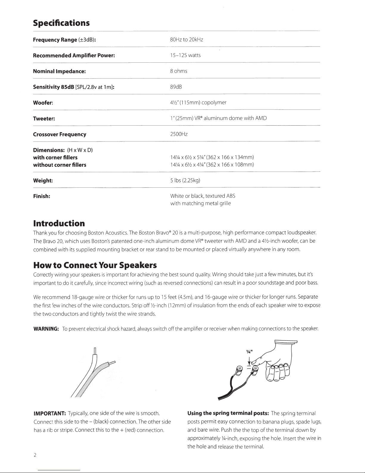
WARNING:
IMPORTANT:
Connect
a rib or strip
as
h
2
speake
ur
yo
fu
re
ca
uge w
-ga
the wire condu
of
s
and
y,
ll
ca
i
the-
e to
nne
Co
e.
portant
im
is
rs
incorrect wir
ce
in
s
y,
ll
cker for
hi
e or t
ir
ors.
ct
tightly twi st the wire
haza
k
oc
sh
l
ica
r
ect
el
the wire is smooth.
of
e
id
one s
tio
ec
conn
k)
lac
(b
(red)
this to th
ct
e+
r achieving t
fo
(such
g
in
s up to
run
off
ip
Str
strands.
ways
al
,
rd
The other si
n.
nn
co
best
he
eve
r
as
fee
15
-inch (12mm)
V2
off
tch
i
sw
de
tion.
ec
und
so
d connection
se
r
),
m
(4.5
t
of
amp
the
si
U
posts
and
approxima
the
qua
and
sulation
in
er
ifi
l
ng
permit
bare
hole
y.
lit
16
or
the
and
wire.
in
Wir
n
ca
s)
ge
gau
from the e
ve
i
rece
spring
easy
Pus
14
ly
te
rel
uld
sho
g
lt
esu
r
wire or t
en
r wh
terminal
connect i
the the top
h
ch,
in
the
ease
ake
t
a poor
in
cker
hi
s of
nd
ng
i
mak
on
exposing t
termi
just a few minutes,
eake
c
Th
tions
run
r wire to e
to the
ring
sp
e
nd
soun
for
h sp
eac
con
posts:
dstage a
longer
ne
to banana plugs,
the terminal down
of
se
In
ole.
h
he
l.
na
but
poor
pa
Se
s.
speake
terminal
spade
the
rt
it's
ss
ba
rate
xpose
ugs,
l
by
e
ir
w
.
r.
in
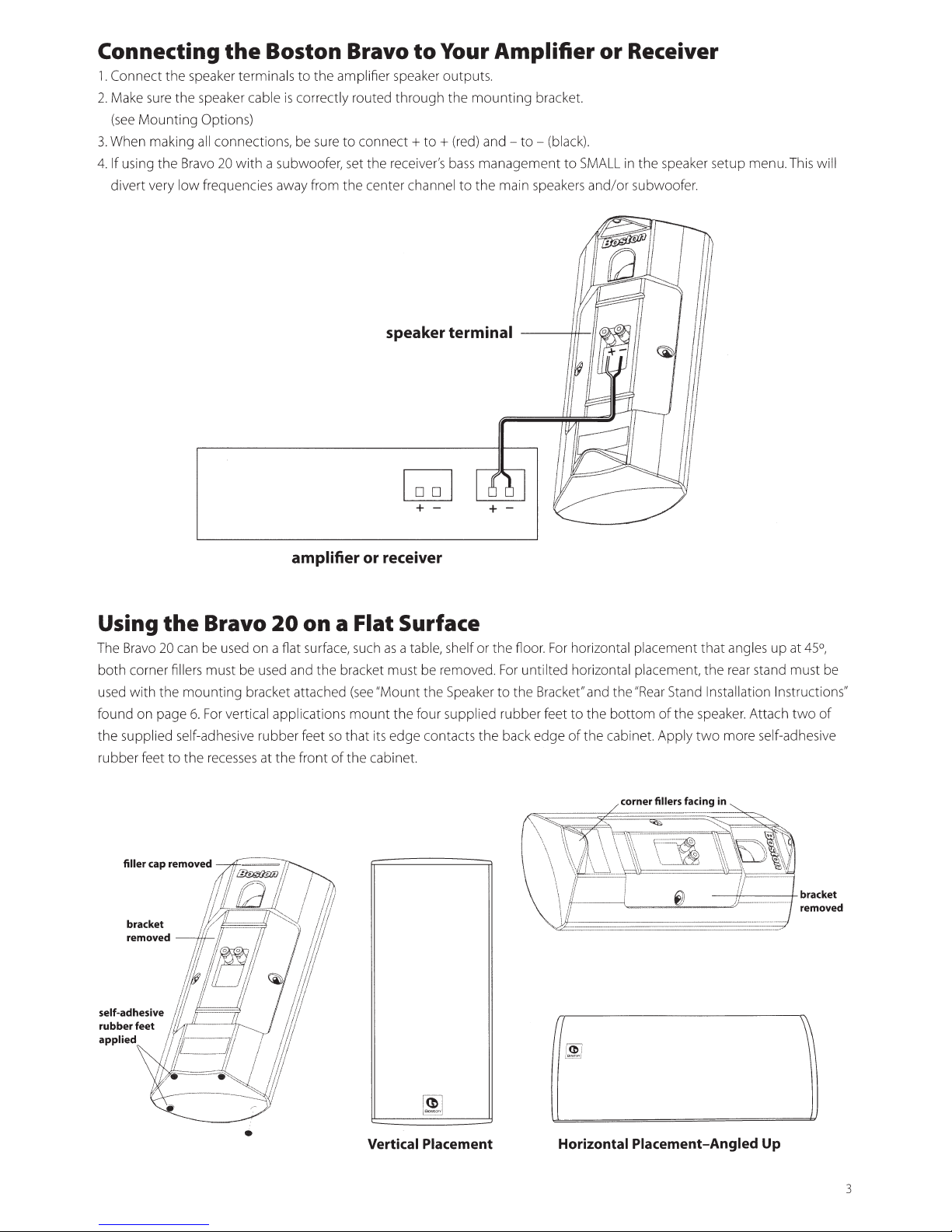
Connecting
1.
Connect
2.
Make sure
(see
3.
When making all connections,
4.
If
divert very
Mount
using
the
the
the
low
the
speaker terminals
speaker cable is correctly routed
ing Options)
Bravo
20
with
frequenci
Boston Bravo
to
the amplifier speaker outputs.
through the
be
sure
to
connect+
a subwoofer, set
es
away from the center channel
the
receiver's
speaker terminal
~
to
Your Amplifier
mounting
to + (red)
and-
bass
management
to the main speakers
+-
bracket.
to-
+-
(bl
ack)
to
or
Receiver
.
SMALL
in the speaker setup menu. This will
and/or
subwoofer.
Using
T
he
both corner fille
used w
found on page 6.
the supplied self-ad
rubber feet to the
the
Bravo
20 can be used on a fiat surface, such as a table,
rs
ith the
mounting bracket atta ched (
filler cap removed
bracket ;
removed
---11!-
If!
;JI
1/jf
Jh
k I 1 f/
'I f
ii/
I
ff
1!·
41
tif!l
jh---------··
//
/L..
·1!£1
1
I I
/:
I I
.
-=
~-===
I I
i'l'
~
!r
J"
'--
_ ..
self-adhes1ve
rubber
applied 1 i
·''
feet
~
amplifier or receiver
Bravo
must be used and t
For
vertical
he
recesses
~
Ill~§ 1~
;/1!
1/.
_d_ ___
I
f//1!------------r!'·
!?
,.
;Y
f~d
71~1/
1/L
- -
"].1
~
l' I •
. / I I
=i
'-"
20
on a Flat Surface
he brac
ket must be remov
see
"Mo
app
lications
sive r
ubb
er feet
at
the front
-=:::::;;;/7'--...,_
!d
if
L
~
__
. __
j(
/ /ll
_ . -
.
·:::....~
!¥
I/
~
.
1
I
1
~
/;
- I /i
'
IT
I I I
·f-r.
..
If
~'>
I
/ I
'
"•iii
·w
;jf
If•
if
;I
Ill
.
; i ; 1 I
,
',,~'
1/
/
'\
! 'I
, 1
I
f/;
!II
II/
1: 1
•
.
! 1!!
1!
I
II
jli
;IJ
so
mount the fo
that
its edge contacts
of
the
cabinet.
Vertical Placement
she
lf
or the
ed. For until ted horizontal placement, the rear
unt the Speaker
ur
supplied rubber feet
the
~l
floor. For
to
the
back
horizontal placement
Bra
cket" and the "Rear Stand Installation Instructions"
to
the
bottom
edge of
the cabinet. Apply
corner fillers facing in
--
Horizontal Placement-Angled
of
the
-"'---~
that
angles
sta
speake
r.
Attach t
two
more self-adhesive
~
-if---
Up
up
at 45°,
nd must be
-+
wo
of
bracket
removed
3
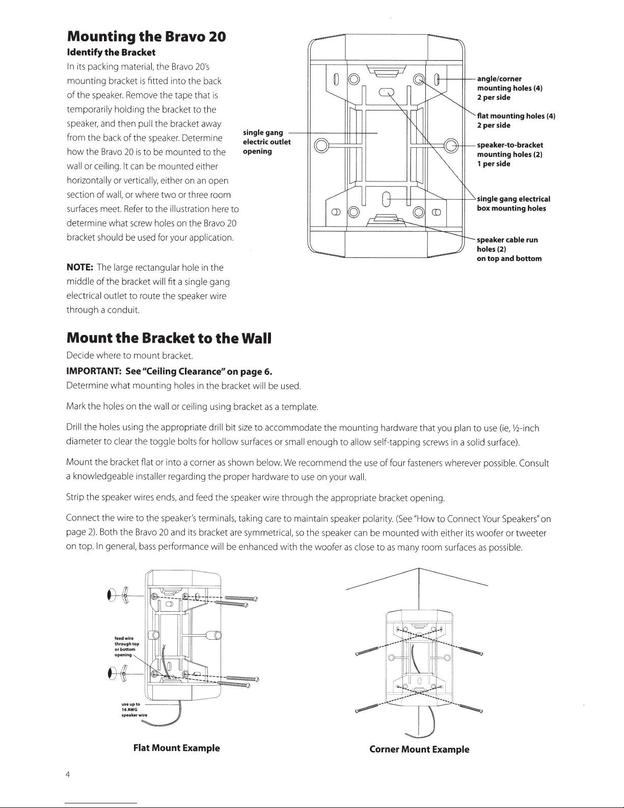
Mounting
Identify
In
mounting
of
temporarily holding
speaker, and
from
how
wall or
horizontally
section
surfaces meet.
determine what screw
bracket
NOTE:
middle
electrical
thr
the
its packing
the speake
the
back
the Bravo
ceilin
of
wa ll,
should
The large rectangular hole
of
the
outlet
ough
a conduit.
Bracket
material,
bracket
r.
Remove
then
of
20
g.
It
can
or
verti
or where
Refer
be
bracket
to route
the
is
pull
the speake
is
to
cally,
to
used
Bravo
the Bravo
fitted
into
the
tape
the bracket
the bracket away
r.
be mounted
be mounted either
either on
two
or three room
the
illustration
holes
on
for your
will
fit
a
the
speaker wire
20's
the back
that
to
th
Determi
to
an
the
Bravo
applicatio
in
single
20
e
open
here to
the
gang
is
ne
the
20
n.
single
gang
electric
opening
-----11f----+++-+-H-
outlet
H--+
-----1ft-
-t---t+----t----"-,--!11---"
angle/
corner
mounting
2 per side
flat mounting
2
speaker-to-bracket
mounting
1 per side
single
box mounting holes
speaker
holes
on
per
top
side
gang
cable
(2)
and
holes (4)
holes
holes (2)
electrical
run
bottom
(4)
Mount
Deci
de
the
where
Bracket
to
mount
bracket.
to
the
IMPORTANT: See"Ceiling Clearance"
Determine what
Mark
the
Drill
th
e
hol
diamet
er
Mount
the
a
knowledgeable installer
Strip
the
speaker wires ends, and feed
Co
nnect
the
page 2
).
Both
on top. In general,
mounting
holes
on
es
us
i
ng
to
clear
bracket flat
wire
the
the
wa
ll
th
e appropriate dri
th
e
toggle
or
int
regarding the proper hardwa
to
th
e spe
Bravo
20
a
bass
performance
ho
l
es
in the bracket
or
ceiling
bo
lt
s
for
o a corner
ak
er
's
term
nd
it
s bracket are
using bracket
ll
holl
as
the
inal
will
Wall
on page
bit
ow
shown
speaker
s,
be enhanced wi
6.
wi
ll
be u
as
si
ze
to
accommodate
surfaces
below.
wi
re
taking care
sy
mm
etri
a
or
sed
.
template.
the
sma
ll
eno
ugh
We
r
ecommend
re
to
use
on
thr
ough
the appropriate bracket opening .
to
maintain speaker
ca
l, so
the
speaker can be
th
the
woofer as
mount
to
your
i
ng
al
low
the use
wall.
polarity.
close to
hardware
se
lf-ta
pping
of
four fasteners
(See
mount
as
many
that
screws in a
"How
ed
wi
ro
om
you
pl
whe
to
Conn
th either
su
rfaces
an
to
use
(ie,
so
lid
s
urf
rever
possible. Consult
ect
Your
it
s woofer
as
possible.
V2
-inc h
ace).
Speakers"
or
tweete
on
r
Flat
Mount
4
Example
Corner
Mount
Example
 Loading...