

Bostitch TU-216-71, TU-216-71A, TU-216-71LN, TU-216-71LM, TU-216-71ALM Operation And Maintenance Manual
...
BEFORE OPERATING THIS TOOL, ALL OPERATORS SHOULD STUDY THIS MANUAL TO UNDERSTAND AND
FOLLOW THE SAFETY WARNINGS AND INSTRUCTIONS. KEEP THESE INSTRUCTIONS WITH THE TOOL
FOR FUTURE REFERENCE. IF YOU HAVE ANY QUESTIONS, CONTACT YOUR BOSTITCH REPRESENTATIVE
OR DISTRIBUTOR.
ANTES DE OPERAR ESTA HERRAMIENTA, TODOS LOS OPERADORES DEBERÁN ESTUDIAR ESTE
MANUAL PARA PODER COMPRENDER Y SEGUIR LAS ADVERTENCIAS SOBRE SEGURIDAD Y LAS
INSTRUCCIONES. MANTENGA ESTAS INSTRUCCIONES CON LA HERRAMIENTA PARA FUTURA
REFERENCIA, SI TIENE ALGUNA DUDA, COMUNÍQUESE CON SU REPRESENTANTE DE BOSTITCH O CON
SU DISTRIBUIDOR.
LIRE ATTENTIVEMENT LE PRÉSENT MANUEL AVANT D’UTILISER L’APPAREIL. PRÉTER UNE ATTENTION
TOUTE PARTICULIÈRE AUX CONSIGNES DE SÉCURITÉ ET AUX AVERTISSEMENTS. GARDER CE MANUEL
AVEC L’OUTIL POUR FUTUR RÉFÉRENCE. SI VOUS AVEZ DES QUESTIONS, CONTACTEZ VOTRE
REPRÉSENTANT OU VOTRE CONCESSIONNAIRE BOSTITCH.
OPERATION and MAINTENANCE MANUAL
MANUAL DE OPERACIÓN Y DE MANTENIMIENTO
MANUEL D’INSTRUCTIONS ET D’ENTRETIEN
TU-216 Series
Industrial Fine Wire Stapler
Grapadora industrial de alambre fino
Agrafeuse industrielle à agrafes fines
121265REVA 6/02
STANLEY FASTENING SYSTEMS

INTRODUCTION
The Bostitch upholstery tackers are precision-built tools, designed for high speed, high
volume fastening. These tools will deliver efficient, dependable service when used correctly
and with care. As with any fine power tool, for best performance the manufacturer's
instructions must be followed. Please study this manual before operating the tool and
understand the safety warnings and cautions. The instructions on installation, operation and
maitenance should be read carefully, and the manual kept for reference. NOTE: Additional
safety measures may be required because of your partic-ular application of the tool. If you
have any questions concerning the tool and its use call Bostitch Customer Service at 1-800556-6696 or write to: Bostitch Customer Service, Briggs Drive, East Greenwich, RI 02818. You
may also consult www.stanleybostitch.com
INDEX
Safety Instructions . . . . . . . . . . . . . . . . . . . . . . . . . . . . . . . 3
Tool Specifications . . . . . . . . . . . . . . . . . . . . . . . . . . . . . . . 4
Air Supply and Connections . . . . . . . . . . . . . . . . . . . . . . . . 5
Loading the Tool . . . . . . . . . . . . . . . . . . . . . . . . . . . . . . . . . 6
Tool Operation . . . . . . . . . . . . . . . . . . . . . . . . . . . . . . . . . . . 7
Power Adjustment Valve. . . . . . . . . . . . . . . . . . . . . . . . . . . 8
Maintaining the Pneumatic Tool . . . . . . . . . . . . . . . . . . . 10
Trouble Shooting . . . . . . . . . . . . . . . . . . . . . . . . . . . . . . . . 11
NOTE:
Bostitch tools have been engineered to provide excellent customer satisfaction and are
designed to achieve maximum performance when used with precision Bostitch fasteners
engineered to the same exacting standards.
Bostitch cannot assume responsibility for product performance if our tools are used with
fasteners or accessories not meeting the specific requirements established for genuine
Bostitch nails, staples and accessories.
LIMITED WARRANTY
Bostitch, Inc., warrants to the original retail purchaser that this product is free from defects in material
and workmanship, and agrees to repair or replace, at Stanley-Bostitch's option, any defective product
within 1 year from the date of purchase. This warranty is not transferable. It only covers damage resulting
from defects in material or workmanship, and it does not cover conditions or malfunctions resulting from
normal wear, neglect, abuse, accident or repairs attempted or made by other than our regional repair
center or authorized warranty service center. Driver blades, bumpers and o-rings are considered normally
wearing parts.
THIS WARRANTY IS IN LIEU OF ALL OTHER EXPRESS WARRANTIES. ANY WARRANTY OF
MERCHANTABILITY OR FITNESS FOR A PARTICULAR PURPOSE IS LIMITED TO THE DURATION OF THIS
WARRANTY. BOSTITCH SHALL NOT BE LIABLE FOR ANY INCIDENTAL OR CONSEQUENTIAL DAMAGES.
This warranty is limited to sales in the United States and Canada. Some states do not allow limitations on
how long an implied warranty lasts, or the exclusion or limitation of incidental or consequential damages,
so the above limitations or exclusions may not apply to you. This warranty gives you specific legal rights,
and you may also have other rights which vary from state to state.
To obtain warranty service, return the product at your expense together with proof of purchase to a
Bostitch Regional or authorized warranty repair center. You may call us at 1-800-556-6696 or on the web
www.stanleybostitch.com for the location of authorized warranty service centers in your area.
-2-
-3-
SAFETY INSTRUCTIONS
EYE PROTECTION which conforms to ANSI specifications and provides protection against flying
particles both from the FRONT and SIDE should ALWAYS be worn by the operator and others in
the work area when loading, operating or servicing this tool. Eye protection is required to guard
against flying fasteners and debris, which could cause severe eye injury.
The employer and/or user must ensure that proper eye protection is worn. Eye protection
equipment must conform to the requirements of the American National Standards Institute, ANSI
Z87.1-1989 and provide both frontal and side protection. NOTE: Non-side shielded spectacles and
face shields alone do not provide adequate protection.
CAUTION:
ADDITIONAL SAFETY PROTECTION will be required in some environments. For example,
the working area may include exposure to noise level which can lead to hearing damage. The
employer and user must ensure that any necessary hearing protection is provided and used by the
operator and others in the work area. Some environments will require the use of head protection
equipment. When required, the employer and user must ensure that head protection conforming to
ANSI Z89.1 1986 is used.
AIR SUPPLY AND CONNECTIONS
Do not use oxygen, combustible gases, or bottled gases as a power source for this tool as tool
may explode, possibly causing injury.
Do not use supply sources which can potentially exceed 200 P.S.I.G. as tool may burst, possibly
causing injury.
The connector on the tool must not hold pressure when air supply is disconnected. If a wrong
fitting is used, the tool can remain charged with air after disconnecting and thus will be able to
drive a fastener even after the air line is disconnected possibly causing injury.
Do not pull trigger or depress contact arm while connected to the air supply as the tool may cycle,
possibly causing injury.
Always disconnect air supply: 1.) Before making adjustments; 2.) When servicing the tool; 3.) When
clearing a jam; 4.) When tool is not in use; 5.) When moving to a different work area, as accidental
actuation may occur, possibly causing injury.
LOADING TOOL
When loading tool: 1.) Never place a hand or any part of body in fastener discharge area of tool;
2.) Never point tool at anyone; 3.) Do not pull the trigger or depress the trip as accidental
actuation may occur, possibly causing injury.
OPERATION
Always handle the tool with care: 1.) Never engage in horseplay; 2.) Never pull the trigger
unless nose is directed toward the work; 3.) Keep others a safe distance from the tool while tool
is in operation as accidental actuation may occur, possibly causing injury.
The operator must not hold the trigger pulled on contact arm tools except during fastening
operation as serious injury could result if the trip accidentally contacted someone or
something, causing the tool to cycle.
Keep hands and body away from the discharge area of the tool. A contact arm tool may bounce
from the recoil of driving a fastener and an unwanted second fastener may be driven possibly
causing injury.
Check operation of the contact arm mechanism frequently. Do not use the tool if the arm is not
working correctly as accidental driving of a fastener may result. Do not interfere with the proper
operation of the contact arm mechanism.
Do not drive fasteners on top of other fasteners or with the tool at an overly steep angle as this
may cause deflection of fasteners which could cause injury.
Do not drive fasteners close to the edge of the work piece as the wood may split, allowing the
fastener to be deflected possibly causing injury.
MAINTAINING THE TOOL
When working on air tools note the warnings in this manual and use extra care when evaluating
problem tools.

-4-
TOOL SPECIFICATIONS
MODEL LENGTH HEIGHT WIDTH WEIGHT
TU-216-71 8.71" (221.25 mm) 5.92” (150.26 mm) 1.58” (40.2 mm) 1.88 lb (.853 kg)
TU-216-71LN 8.71" (221.25 mm) 7.81” (198.30 mm) 1.58” (40.2 mm) 2.01 lb (.912 kg)
TU-216-71LM 13.925” (353.69 mm) 5.92” (150.26 mm) 1.58” (40.2 mm) 2.34 lb (1.061 kg)
TU-216-71A 8.71” (221.25 mm) 5.92” (150.26 mm) 1.58” (40.2 mm) 1.91 lb (.867 kg)
TU-216-71ALM 13.925” (353.69 mm) 5.92” (150.26 mm) 1.58” (40.2 mm) 2.37 lb (1.075 kg)
TU-216-80 8.71” (221.25 mm) 5.92” (150.26 mm) 1.58” (40.2 mm) 1.82 lb (.807 kg)
TU-216-80LN 8.71" (221.25 mm) 7.81” (198.30 mm) 1.58” (40.2 mm) 1.97 lb (.894 kg)
TU-216-80LM 13.925” (353.69 mm) 5.92” (150.26 mm) 1.58” (40.2 mm) 2.23 lb (1.012 kg)
TU-216-80ALM 13.925” (353.69 mm) 5.92” (150.26 mm) 1.58” (40.2 mm) 2.26 lb (1.025 kg)
TU-216-84 8.71” (221.25 mm) 5.92” (150.26 mm) 1.58” (40.2 mm) 1.82 lb (.826 kg)
TU-216-97 8.71” (221.25 mm) 5.92” (150.26 mm) 1.58” (40.2 mm) 1.79 lb (.813 kg)
TU-216-SJK 8.71” (221.25 mm) 5.92” (150.26 mm) 1.58” (40.2 mm) 1.79 lb (.813 kg)
TOOL MODEL STAPLE SERIES CROWN WIDTH WIRE SIZE FASTENER RANGE
TU-216-71 BA71 3/8” (9.0 mm) .023X.030(.58mmX.75mm) 5/32"-5/8"(4mm-16mm)
TU-216-71LN BA71 3/8” (9.0 mm) .023X.030(.58mmX.75mm) 5/32"-5/8"(4mm-16mm)
TU-216-71LM BA71 3/8” (9.0 mm) .023X.030(.58mmX.75mm) 5/32"-5/8"(4mm-16mm)
TU-216-71A BA71 3/8” (9.0 mm) .023X.030(.58mmX.75mm) 5/32"-5/8"(4mm-16mm)
TU-216-71ALM BA71 3/8” (9.0 mm) .023X.030(.58mmX.75mm) 5/32"-5/8"(4mm-16mm)
TU-216-80 BA80 1/2” (13mm) .027X.036(.69mmX.91mm) 5/32”-5/8”(4mm-16mm)
TU-216-80LN BA80 1/2” (13mm) .027X.036(.69mmX.91mm) 5/32”-5/8”(4mm-16mm)
TU-216-80LM BA80 1/2” (13mm) .027X.036(.69mmX.91mm) 5/32”-5/8”(4mm-16mm)
TU-216-80ALM BA80 1/2” (13mm) .027X.036(.69mmX.91mm) 5/32”-5/8”(4mm-16mm)
TU-216-84 SBNK, ATRO 84 31/64”(12.3mm) .023X.040(.55mmX1mm) 5/32”-5/8”(4mm-16mm)
TU-216-97 BA97 3/16”(4.8mm) .027X.036(.69mmX.91mm) 5/32’-5/8”(4mm-16mm)
TU-216-SJK ATRO SJK 5/32”(4.1mm) .024X.029(.60mmX.70mm) 5/32”-5/8”(4mm-16mm)
All screws and nuts are metric
FASTENER SPECIFICATIONS
TOOL AIR FITTING
This tool uses a free-flow connector plug, 1/4 N.P.T. The inside diameter should be .200”
(5mm) or larger. The fitting must be capable of discharging tool air pressure when
disconnected from the air supply.
OPERATING PRESSURE
70 to 100 p.s.i.g. (4.8 to 6.9 bar). Select the operating pressure within this range for best
fastener performance.
DO NOT EXCEED THE RECOMMENDED OPERATING PRESSURE.
AIR CONSUMPTION
The TU-216 requires 1.71 cubic feet per minute (.048 cubic meters) and the TU-216-LN
models require 1.84 cubic feet per minute (.052 cubic meters) of free air to operate at the
rate of 100 nails per minute, at 80 p.s.i. (5.5 bar). Take the actual rate at which the tool
will be run to determine the amount of air required. For instance, if your fastener usage
averages 50 nails per minute, you need 50% of the tool’s c.f.m. which is required to
operate the tool at 100 nails per minute.

AIR SUPPLY AND CONNECTIONS
Do not use oxygen, combustible gases, or bottled gases as a power
source for this tool as tool may explode, possibly causing injury.
Fittings:
Install a male plug on the tool which is free flowing and which will release air pressure
from the tool when disconnected from the supply source.
Hoses:
Air hoses should have a minimum of 150 p.s.i. (10.34 bar) working pressure rating or
150 percent of the maximum pressure that could be produced in the air system. The
supply hose should contain a fitting that will provide “quick disconnecting” from the
male plug on the tool.
Supply Source:
Use only clean regulated compressed air as a power source for this tool. NEVER USE
OXYGEN, COMBUSTIBLE GASES, OR BOTTLED GASES, AS A POWER SOURCE FOR THIS
TOOL AS TOOL MAY EXPLODE.
Regulator:
A pressure regulator with an operating pressure of 0 - 125 p.s.i. (0 - 8.6 bar) is required to
control the operating pressure for safe operation of this tool. Do not connect this tool to
air pressure which can potentially exceed 200 p.s.i. (13.8 bar) as tool may fracture or
burst, possibly causing injury.
Operating Pressure:
Do not exceed recommended maximum operating pressure as tool wear will be greatly
increased. The air supply must be capable of maintaining the operating pressure at the
tool. Pressure drops in the air supply can reduce the tool’s driving power. Refer to “TOOL
SPECIFICATIONS” for setting the correct operating pressure for the tool.
Filter:
Dirt and water in the air supply are major causes of wear in pneumatic tools. A filter will
help to get the best performance and minimum wear from the tool. The filter must have
adequate flow capacity for the specific installation. The filter has to be kept clean to be
effective in providing clean compressed air to the tool. Consult the manufacturer’s
instructions on proper maintenance of your filter. A dirty and clogged filter will cause a
pressure drop which will reduce the tool’s performance.
-5-
-6-
EYE PROTECTION which conforms to ANSI specifications and provides
protection against flying particles both from the FRONT and SIDE should
ALWAYS be worn by the operator and others in the work area when loading,
operating or servicing this tool. Eye protection is required to guard against
flying fasteners and debris, which could cause severe eye injury.
The employer and/or user must ensure that proper eye protection is worn. Eye
protection equipment must conform to the requirements of the American National Standards
Institute, ANSI Z87.1-1989 and provide both frontal and side protection. NOTE: Non-side
shielded spectacles and face shields alone do not provide adequate protection.
TO PREVENT ACCIDENTAL INJURIES:
• Never place a hand or any other part of the body in nail discharge area of tool while the air
supply is connected.
• Never point the tool at anyone else.
•Never engage in horseplay.
• Never pull the trigger unless nose is directed at the work.
•Always handle the tool with care.
• Do not pull the trigger while loading the tool.
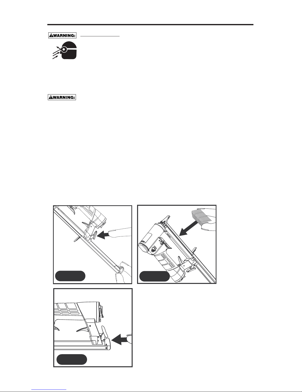
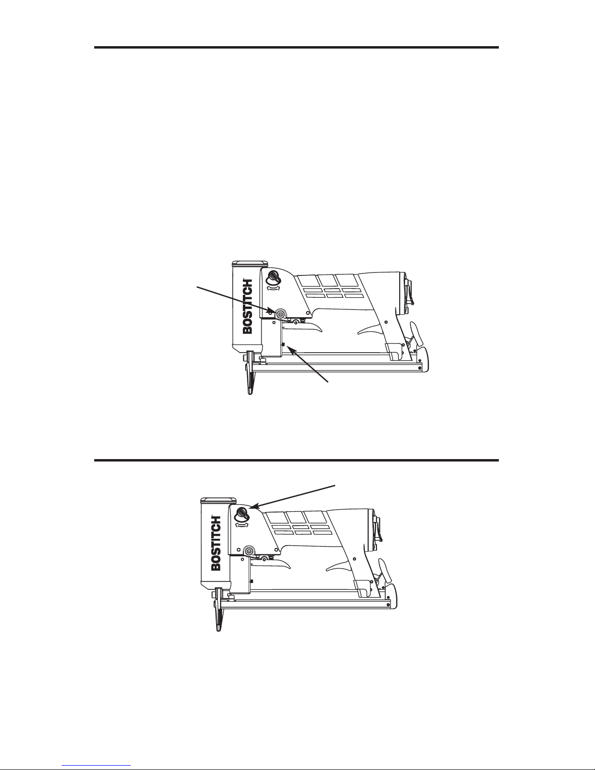
LOADING THE TU-216
Loading
1. Turn tool sideways with discharge area pointed away from yourself and others.
Depress the quick release latch inside the tool frame or the latch on the rear of the
main frame. Slide rail to rear.
2. Drop staple stick into magazine.
3. Push rail forward until the latch closes. The tool is now ready for use.
FIG 1
FIG 3
FIG 2
EYE PROTECTION which conforms to ANSI specifications and provides
protection against flying particles both from the FRONT and SIDE should
ALWAYS be worn by the operator and others in the work area when loading,
operating or servicing this tool. Eye protection is required to guard against
flying fasteners and debris, which could cause severe eye injury.
The employer and/or user must ensure that proper eye protection is worn. Eye
protection equipment must conform to the requirements of the American National Standards
Institute, ANSI Z87.1-1989 and provide both frontal and side protection. NOTE: Non-side
shielded spectacles and face shields alone do not provide adequate protection.
TOOL OPERATION
MODEL IDENTIFICATION
Refer to Tool Operation Check on page 9 before proceeding to use this tool.
BEFORE HANDLING OR OPERATING THIS TOOL:
I. READ AND UNDERSTAND THE WARNINGS CONTAINED IN THIS MANUAL.
II. REFER TO “TOOL SPECIFICATIONS” IN THIS MANUAL TO
IDENTIFY THE OPERATING SYSTEM ON YOUR TOOL.
BOSTITCH offers two types of Operation for the TU-216 series tools.
-7-
Trigger Operated:
Identified by
No Speed Adjustment
No Trigger Free Play Adjustment
Automatic:
Identified by
Speed Adjustment
Trigger Free Play Adjustment
Speed Adjustment
Trigger Free Play Adjustment
-8-
For Maximum Power: Rotate valve counterclockwise as far as possible.
To Reduce Power: Rotate valve clockwise for up to 30% reduction.
Trigger Operated:
The Trigger Operated model is cycled by actuation of the trigger.
The Trigger Operated tool will cycle each time the trigger is actuated.
Automatic:
The automatic model is cycled by actuation of the trigger. When the trigger is pulled lightly
with a short motion the tool will drive one fastener. When the trigger is pulled as far as
possible the tool will continuously drive fasteners automatically until the trigger is released.
The rate at which fasteners are driven in the automatic mode is adjustable. The speed
adjustment screw is located on the left side of the tool in the trigger valve area. Turning the
screw in a counter clockwise direction increases speed and in a clockwise direction
decreases speed. This model also includes a trigger free play adjustment to adjust the
amount of trigger stroke between single and automatic operation. Turning the adjustment
knob to the left increases the trigger travel from single actuation to automatic.
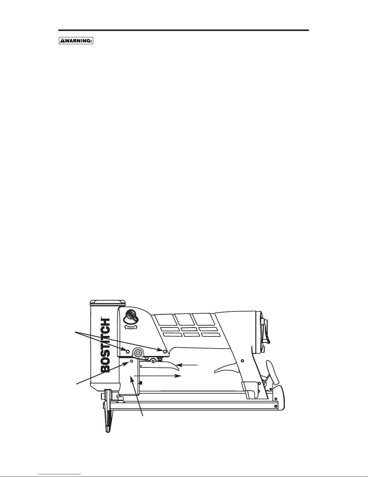
MODEL IDENTIFICATION (Continued)
POWER ADJUSTMENT VALVE
Speed Adjustment
Trigger Free Play Adjustment
Power Adjustment Knob

TOOL OPERATION CHECK:
CAUTION: Remove all fasteners from tool before performing tool operation check.
1. Trigger Operated Tool:
A. With finger off the trigger, hold the tool with a firm grip on the handle.
B. Place the nose of the tool against the work surface.
C. Pull the trigger to cycle the tool. Release the trigger and cycle is complete.
CAUTION:
THE TOOL WILL CYCLE EACH TIME THE TRIGGER IS PULLED!
2. Automatic Tool:
A. With finger off the trigger, hold the tool with a firm grip on the handle.
B. Place the nose of the tool against the work surface.
C. Single cycle mode:
Lightly pull the trigger for a single cycle. Release the trigger and cycle is complete.
CAUTION:
THE TOOL WILL CYCLE EACH TIME THE TRIGGER IS PULLED!
D. Automatic mode:
Pull trigger as far as possible to depress both valve stems. Release the trigger to stop.
CAUTION:
THE TOOL WILL CYCLE AT UP TO 30 TIMES A SECOND IN AUTOMATIC MODE.
-9-
IN ADDITION TO THE OTHER WARNINGS CONTAINED IN THIS MANUAL OBSERVE
THE FOLLOWING FOR SAFE OPERATION
• Use the BOSTITCH pneumatic tool only for the purpose for which it was designed.
• Never use this tool in a manner that could cause a fastener to be directed toward the user
or others in the work area.
• Do not use the tool as a hammer.
• Always carry the tool by the handle. Never carry the tool by the air hose.
• Do not alter or modify this tool from the original design or function without approval from
BOSTITCH, INC.
•Always be aware that misuse and improper handling of this tool can cause injury to
yourself and others.
• Never clamp or tape the trigger or contact trip in an actuated position.
• Never leave a tool unattended with the air hose attached.
• Do not operate this tool if it does not contain a legible WARNING LABEL.
• Do not continue to use a tool that leaks air or does not function properly. Notify your nearest
Bostitch representative if your tool continues to experience functional problems.
-10-
MAINTAINING THE PNEUMATIC TOOL
When working on air tools, note the warnings in this manual and use extra
care evaluating problem tools.
Replacement Parts:
BOSTITCH replacement parts are recommended. Do not use modified parts or parts which
will not give equivalent performance to the original equipment.
Assembly procedure for seals:
When repairing a tool, make sure the internal parts are clean and lubricated. Use
MAGNALUBE or equivalent on all “O”-rings. Coat each “O”-ring with MAGNALUBE before
assembling. Use a small amount of oil on all moving surfaces and pivots.
Air Supply - Pressure and Volume:
Air volume is as important as air pressure. The air volume supplied to the tool may be
inadequate because of undersize fittings and hoses, or from the effects of dirt and water in
the system. Restricted air flow will prevent the tool from receiving an adequate volume of air,
even though the pressure reading is high. The results will be slow operation, misfeeds or
reduced driving power. Before evaluating tool problems for these symptoms, trace the air
supply from the tool to the supply source for restrictive connectors, swivel fittings, low points
containing water and anything else that would prevent full volume flow of air to the tool.
Trigger Valve Removal:
Automatic
1. Remove trigger pivot pin.
2. Remove trigger.
3. To remove trigger free play adjustment housing pull in direction of arrow until it is clear of
valve.
4. Remove two trigger valve pins and remove trigger valve.
Standard Valve
Remove two trigger valve pins (item 4) and remove trigger valve.
4
2
1
Pull
3
 Loading...