

Bostitch SL1838BC Operation And Maintenance Manual
BEFORE OPERATING THIS TOOL, ALL OPERATORS SHOULD STUDY THIS MANUAL
TO UNDERSTANDAND FOLLOWTHE SAFETYWARNINGS ANDINSTRUCTIONS.KEEP
THESE INSTRUCTIONSWITHTHETOOL FOR FUTURE REFERENCE.IFYOU HAVE ANY
QUESTIONS, CONTACTYOUR BOSTITCH REPRESENTATIVE OR DISTRIBUTOR.
ANTES DE OPERAR ESTA HERRAMIENTA, TODOS LOS OPERADORES DEBERÁN
ESTUDIAR ESTE MANUAL PARA PODER COMPRENDER Y SEGUIR LAS
ADVERTENCIAS SOBRE SEGURIDAD Y LAS INSTRUCCIONES. MANTENGA ESTAS
INSTRUCCIONES CON LA HERRAMIENTA PARA FUTURA REFERENCIA, SI TIENE
ALGUNADUDA, COMUNÍQUESECON SU REPRESENTANTE DE BOSTITCH O CON SU
DISTRIBUIDOR.
LIRE ATTENTIVEMENT LE PRÉSENT MANUEL AVANT D’UTILISER L’APPAREIL.
PRÉTER UNE ATTENTIONTOUTE PARTICULIÈRE AUX CONSIGNES DE SÉCURITÉ ET
AUX AVERTISSEMENTS. GARDER CE MANUEL AVEC L’OUTIL POUR FUTUR
RÉFÉRENCE. SI VOUS AVEZ DES QUESTIONS, CONTACTEZ VOTRE REPRÉSENTANT
OUVOTRE CONCESSIONNAIRE BOSTITCH.
OPERATION and MAINTENANCE MANUAL
MANUAL DE OPERACIÓNY DE MANTENIMIENTO
MANUEL D’INSTRUCTIONS ET D’ENTRETIEN
SL1838BC
BOSTITCH CAP STAPLER
CONJUNTO DE GRAPADORA DE SOMBRERETES BOSTITCH
NÉCESSAIRE D’AGRAFEUSE DE CAPUCHON BOSTITCH
STANLEY FASTENING SYSTEMS
188677REVA 10/09

INTRODUCTION
T
he Bostitch SL1838BC is a precision-built tool, designed for high speed, high volume fastening. These tools
will deliver efficient, dependable service when used correctly and with care. As with any fine tool, for best
performance the manufacturer’s instructions must be followed. Please study this manual before operating the
tool and understand the safety warnings and cautions. The instructions on installation, operation and
m
aintenance should be read carefully, and the manual kept for reference. NOTE: Additional safety measures
may be required because of your particular application of the tool. If you have any questions concerning the
t
ool and its use call Bostitch Customer Service at 1-800-556-6696 or write to: Bostitch Customer Service,
Briggs Drive, East Greenwich, RI 02818.You may also consult www.bostitch.com
INDEX
S
afety Instructions/Warnings . . . . . . . . . . . . . . . . . . . . . . . . . . . . 3
T
ool/Fastener Specifications . . . . . . . . . . . . . . . . . . . . . . . . . . . . . 4
Tool/Trip Operation . . . . . . . . . . . . . . . . . . . . . . . . . . . . . . . . . . . . . 5
Air Supply and Connections. . . . . . . . . . . . . . . . . . . . . . . . . . . . . . 6
Loading Staples . . . . . . . . . . . . . . . . . . . . . . . . . . . . . . . . . . . . . . 7
Installing the Short Nail Guide . . . . . . . . . . . . . . . . . . . . . . . . . . . . 8
Loading Caps. . . . . . . . . . . . . . . . . . . . . . . . . . . . . . . . . . . . . . . . . 9
Dial-A-Depth™ Control, Trigger Lockout . . . . . . . . . . . . . . . . . . . 10
Tool Operation Check . . . . . . . . . . . . . . . . . . . . . . . . . . . . . . . . 11
Maintaining the Pneumatic Tool . . . . . . . . . . . . . . . . . . . . . . . . . 11
Maintenance Checklist. . . . . . . . . . . . . . . . . . . . . . . . . . . . . . . . . 12
Troubleshooting . . . . . . . . . . . . . . . . . . . . . . . . . . . . . . . . . . . . . 13
Available Accessories . . . . . . . . . . . . . . . . . . . . . . . . . . . . . . . . . 14
NOTE:
Bostitch tools have been engineered to provide excellent customer satisfaction and are designed to achieve
maximum performance when used with precision Bostitch fasteners engineered to the same exacting
standards. Bostitch cannot assume responsibility for product performance if our tools are used with
fasteners or accessories not meeting the specific requirements established for genuine Bostitch nails,
staples and accessories.
LIMITED WARRANTY — U.S. and Canada Only
Effective December 1, 2005, Bostitch, L.P. warrants to the original retail purchaser that the product purchased is
free from defects in material and workmanship, and agrees to repair or replace, at Bostitch’s option, any defective
Bostitch branded pneumatic stapler or nailer for a period of seven (7) years from date of purchase (one (1) year
from the date of purchase for compressors and tools used in production applications).Warranty is not transferable.
Proof of purchase date required. This warranty covers only damage resulting from defects in material or
workmanship; it does not cover conditions or malfunctions resulting from normal wear, neglect, abuse, accident or
repairs attempted or made by other than our national repair center or authorized warranty service centers. Driver
blades, bumpers, o-rings, pistons and piston rings are considered normally wearing parts.For optimal performance
of your Bostitch tool always use genuine Bostitch fasteners and replacement parts.
THIS WARRANTY IS IN LIEU OF ALL OTHER WARRANTIES, EXPRESS OR IMPLIED, INCLUDING BUT NOT
LIMITED TO THE IMPLIED WARRANTIES OF MERCHANTABILITY OR FITNESS FOR A PARTICULAR
PURPOSE. BOSTITCH SHALL NOT BE LIABLE FOR ANY INCIDENTAL OR CONSEQUENTIAL DAMAGES.
Some states and countries do not allow limitations on how long an implied warranty lasts, or the exclusion or limitation
of incidentalor consequential damages,so the abovelimitations orexclusions may not applyto you.Thiswarranty gives
you specific legal rights, and you may also have other rights which vary from state to state and country to country.
To obtain warranty service in the U.S. return the product, together with proof of purchase, to the U.S. Bostitch
National or Regional Independent Authorized Warranty Service Center. In the U.S. you may call us at 1-800556-6696 or visit www.BOSTITCH.com for the location most convenient for you. In Canada please call us at
800-567-7705 or visit www.BOSTITCH.com
2
SAFETY INSTRUCTIONS
E
YE PROTECTIONwhich conforms to ANSI specifications and provides protection against
flying particles both from the FRONT and SIDE should ALWAYS be worn by the operator and
others in the work area when connecting to air supply, loading, operating or servicing this
tool. Eye protection is required to guard against flying fasteners and debris, which could
c
ause severe eye injury.
T
he employer and/or user must ensure that proper eye protection is worn. Eye protection
e
quipment must conform to the requirements of the American National Standards Institute,
ANSI Z87.1 and provide both frontal and side protection. NOTE: Non-side shielded
spectacles and face shields alone do not provide adequate protection.
C
AUTION:
A
dditional Safety Protection will be required in some environments. For example,
the working area may include exposure to noise level which can lead to hearing damage.
The employer and user must ensure that any necessary hearing protection is provided and
u
sed by the operator and others in the work area. Some environments will require the use
of head protection equipment.When required, the employer and user must ensure that head
p
rotection conforming to ANSI Z89.1 is used.
AIR SUPPLY AND CONNECTIONS
Do not use oxygen, combustible gases, or bottled gases as a power source for this tool as
tool may explode, possibly causing injury.
Do not use supply sources which can potentially exceed 200 P.S.I.G. as tool may burst,
possibly causing injury.
The connector on the tool must not hold pressure when air supply is disconnected. If a
wrong fitting is used, the tool can remain charged with air after disconnecting and thus will
be able to drive a fastener even after the air line is disconnected possibly causing injury.
Do not pull trigger or depress contact arm while connected to the air supply as the tool may
cycle, possibly causing injury.
Always disconnect air supply: 1.) Before making adjustments; 2.) When servicing the tool;
3.) When clearing a jam; 4.) When tool is not in use; 5.)When moving to a different work area,
as accidental actuation may occur, possibly causing injury.
LOADING TOOL
When loading tool: 1.) Never place a hand or any part of body in fastener discharge area of
tool; 2.) Never point tool at anyone; 3.) Do not pull the trigger or depress the trip as
accidental actuation may occur, possibly causing injury.
OPERATION
Always handle the tool with care: 1.) Never engage in horseplay; 2.) Never pull the trigger
unless nose is directed toward the work; 3.) Keep others a safe distance from the tool while
tool is in operation as accidental actuation may occur, possibly causing injury.
The operator must not hold the trigger pulled on contact arm tools except during fastening
operation as serious injury could result if the trip accidentally contacted someone or
something, causing the tool to cycle.
Keep hands and body away from the discharge area of the tool. A contact arm tool may
bounce from the recoil of driving a fastener and an unwanted second fastener may be
driven possibly causing injury.
Check operation of the contact arm mechanism frequently. Do not use the tool if the arm is
not working correctly as accidental driving of a fastener may result. Do not interfere with
the proper operation of the contact arm mechanism.
Do not drive fasteners on top of other fasteners or with the tool at an overly steep angle as
this may cause deflection of fasteners which could cause injury.
Do not drive fasteners close to the edge of the work piece as the wood may split, allowing
the fastener to be deflected possibly causing injury.
This nailer produces SPARKS during operation. NEVER use the nailer near flammable
substances, gases or vapors including lacquer, paint, benzine, thinner, gasoline, adhesives,
mastics, glues or any other material that is -- or the vapors, fumes or byproducts of which are -flammable, combustible or explosive. Using the nailer in any such environment could cause an
EXPLOSION resulting in personal injury or death to user and bystanders.
3
MAINTAINING THE TOOL
When working on air tools note the warnings in this manual and use extra care when
evaluating problem tools.
Tool Model Fastener Type
SL1838BC
4
TOOL SPECIFICATIONS
All dimensions in inches unless otherwise specified.
Operating Pressure:
70 to 120 p.s.i.g. (4.9 to 8.43 kg/cm2). Select the operating pressure within in this range for best fastener
performance.
DO NOT EXCEED THIS RECOMMENDED OPERATING PRESSURE.
Air Consumption:
The SL1838BC requires 2.83 cubic feet per minute or C.F.M. (80.1 liters per minute or LT/MIN) of free air at
80PSI (5.6 kg/cm
2
) to operate at a rate of 60 fasteners per minute. To determine the appropriately sized air
compressor, take the actual rate at which the tool will be run and compare the required C.F.M. (LT/MIN) to
the compressors free air delivery (C.F.M./ LT/MIN) at 80 PSI (5.6 kg/cm
2
).
For example, if your fastener usage averages 30 fasteners per minute, you need 50% of the tool’s C.F.M.
required to operate the tool at the rate of 60 fasteners per minute. In this case, be sure that your air
compressor can deliver a minimum of 1.42 C.F.M. (40.2 LT/MIN) at 80 PSI(5.6 kg/cm
2
) for optimum
performance.
FASTENER SPECIFICATIONS
NOTE:
BOSTITCH tools have been engineered to provide superior customer satisfaction and are designed to achieve
maximum performance when used with precision BOSTITCH fasteners engineered to the same exacting
standards. BOSTITCH cannot assume responsibility for product performance if our tools are used with
fasteners or accessories not meeting the specific requirements established for genuine BOSTITCH
fasteners and accessories.
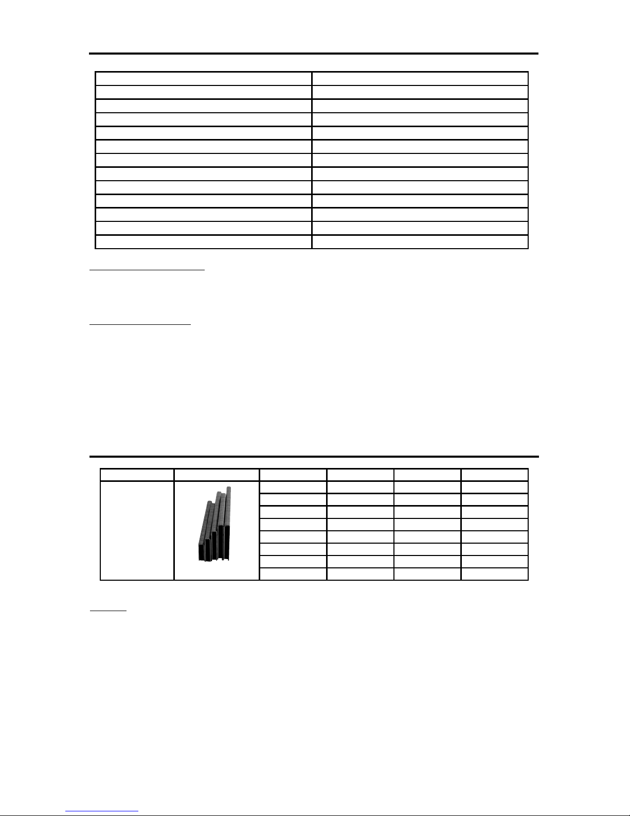
Staples
S
L1838BC
Description 18ga Cap Stapler
E
ngine Type
O
il-Free
Operation Pressure Range
70-120 PSI (4.9 to 8.43kg/cm2)
M
aximum Operation Pressure
120 PSI (8.43 kg/cm2)
F
astener Type
S
L5035 Series
Fastener Gauge 18 Gauge
F
astener Range
3
/4” - 1-1/2”(19mm-38mm)
M
agazine Capacity
1
63
L
ength
1
1-1/4” (286mm)
Width 6-1/4” (159mm)
Height 10-1/2” (267mm)
Weight 3.9lbs. (1.77kg)
Fastener SKU Crown Width Gauge Length
SL50355/8G 5/16” 18 5/8” (15mm)
SL50353/4G 5/16” 18 3/4” (19mm)
SL50351G 5/16” 18 1” (25mm)
SL50351-1/8G 5/16” 18 1-1/8” (28mm)
SL50351-3/16G 5/16” 18 1-3/16” (30mm)
SL50351-1/4G 5/16” 18 1-1/4” (32mm)
SL50351-3/8G 5/16” 18 1-3/8” (35mm)
SL50351-1/2G 5/16” 18 1-1/2” (38mm)
5
TRIP OPERATION MODE
Warning: Always disconnect air supply before making adjustments as accidental actuation may occur,
possibly causing injury.
The SL1838BC features a selectable trigger system that allows the user to choose between the
following modes of operation:
1. Contact Trip Operation 2. SequentialTrip Operation
1. CONTACT TRIP:
The common operation procedure on “Contact Trip” tools is for the operator to contact the work surface to
actuate the trip mechanism while keeping the trigger pulled, thus driving a fastener each time the work
surface is contacted. This will allow rapid fastener placement on many jobs. All pneumatic tools are subject
to recoil when driving fasteners.The tool may bounce, releasing the trip, and if unintentionally allowed to recontact the work surface with the trigger still actuated (finger still holding the trigger pulled) an unwanted
second fastener will be driven.
2. SEQUENTIAL TRIP:
The Sequential Trip requires the operator to hold the tool against the work before pulling the trigger. This
makes accurate fastener placement easier. The Sequential Trip allows exact fastener location without the
possibility if driving a second fastener on recoil as described under “Contact Trip”. The Sequential Trip Tool
has a positive advantage because it will not accidentally drive a fastener if the tool is contacted against the
work surface - or anything else - while the operator is holding the trigger pulled.
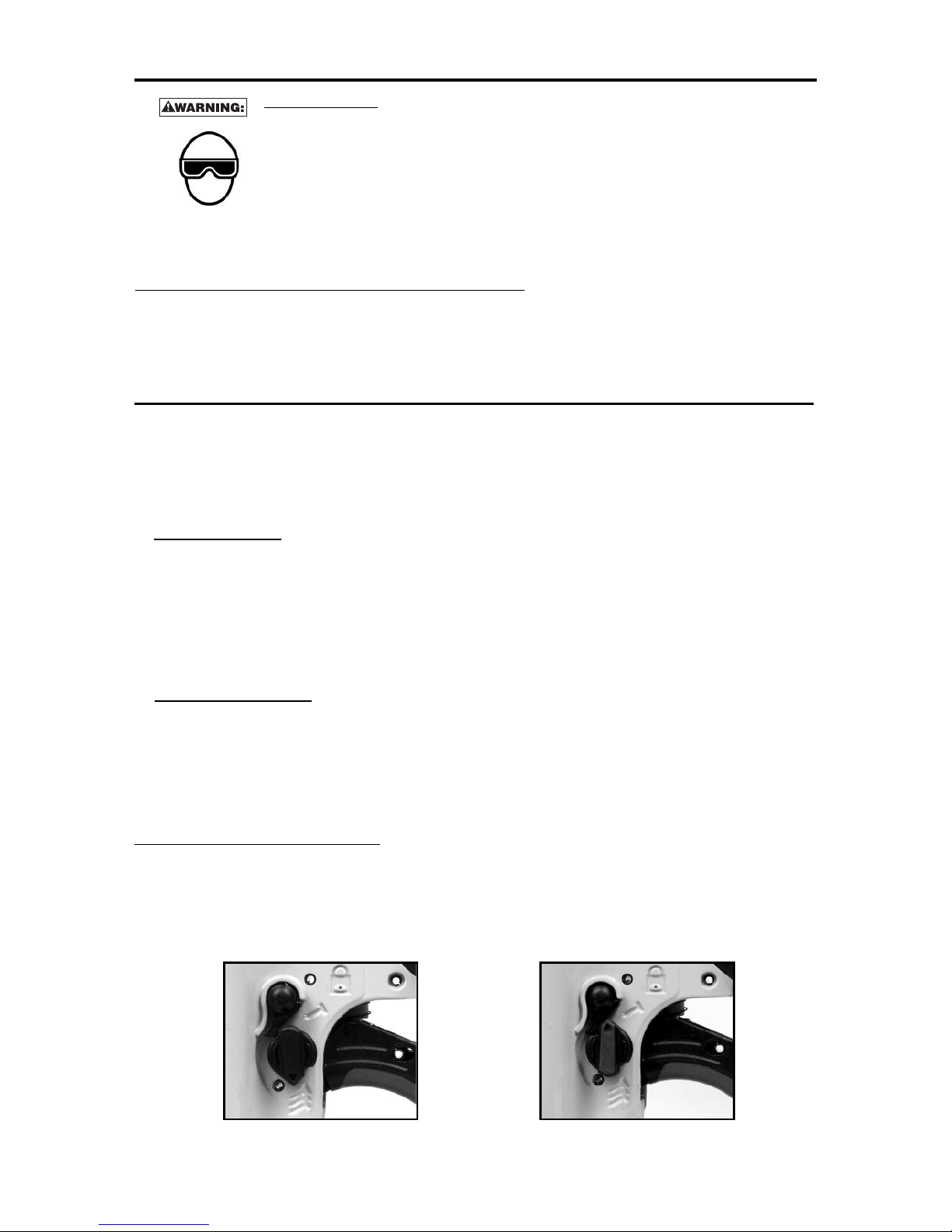
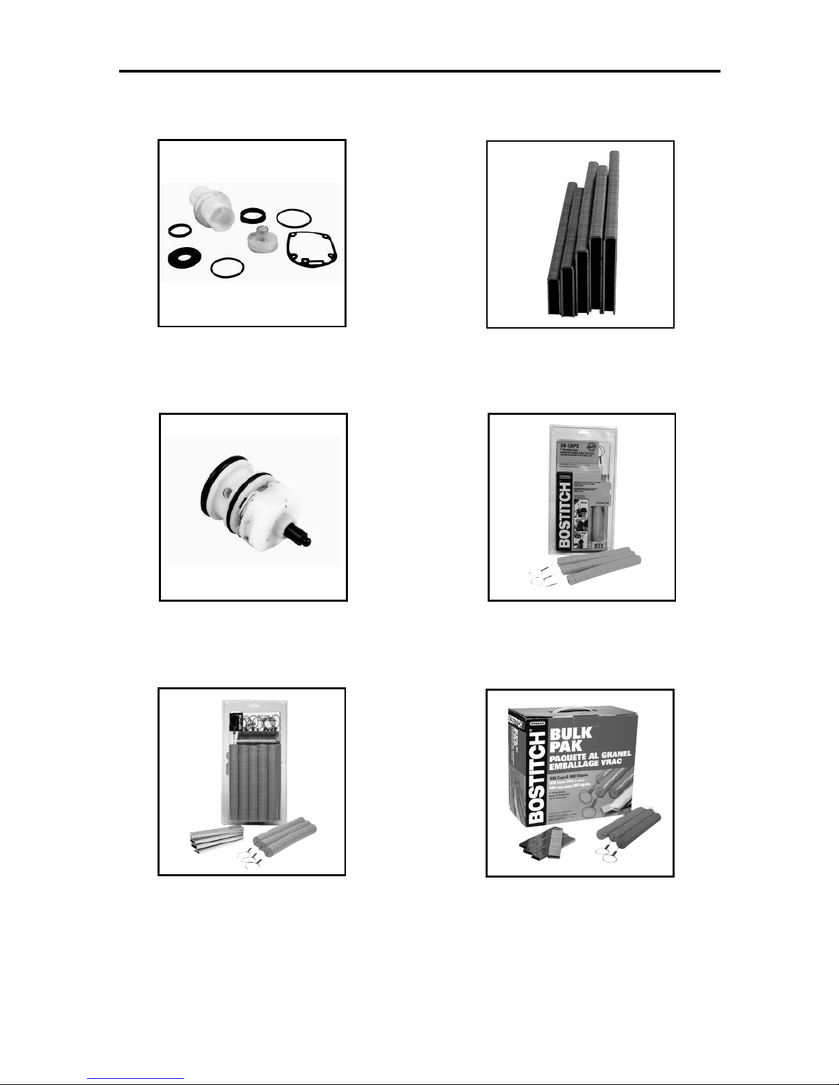
SELECTING THE TRIP MODE:
To ensure safety, the user must lock the trigger (as described above) before changing the trigger system. To
change the trip mode, rotate the mode switch in the counterclockwise direction. The mode switch will lock
automatically when the indicating arrow is pointing down to the 3 nail icon stamped into the tool frame
(Contact Trip Mode) or to a single nail icon stamped in the tool frame( Sequential Trip Mode). Unlock the
trigger to resume tool operation.
Contact Trip Mode
Sequential Trip Mode
(trip mode selector switch pointing down) (trip mode selector switch pointing up)
TOOL OPERATION
EYE PROTECTION which conforms to ANSI specifications and provides protection
against flying particles both from the FRONT and SIDE should ALWAYS be worn by the
operator and others in the work area when loading, operating or servicing this tool. Eye
protection is required to guard against flying fasteners and debris, which could cause
severe eye injury.
T
he employer and/or user must ensure that proper eye protection is worn. Eye
p
rotection equipment must conform to the requirements of the American National
Standards Institute, ANSI Z87.1 and provide both frontal and side protection. NOTE: Nonside shielded spectacles and face shields alone do not provide adequate protection.
BEFORE HANDLING OR OPERATING THIS TOOL:
I. READ AND UNDERSTANDTHE WARNINGS CONTAINED IN THIS MANUAL.
II. REFER TO “TOOL SPECIFICATIONS” INTHIS MANUALTO IDENTIFYTHE
OPERATING SYSTEM ONYOURTOOL.
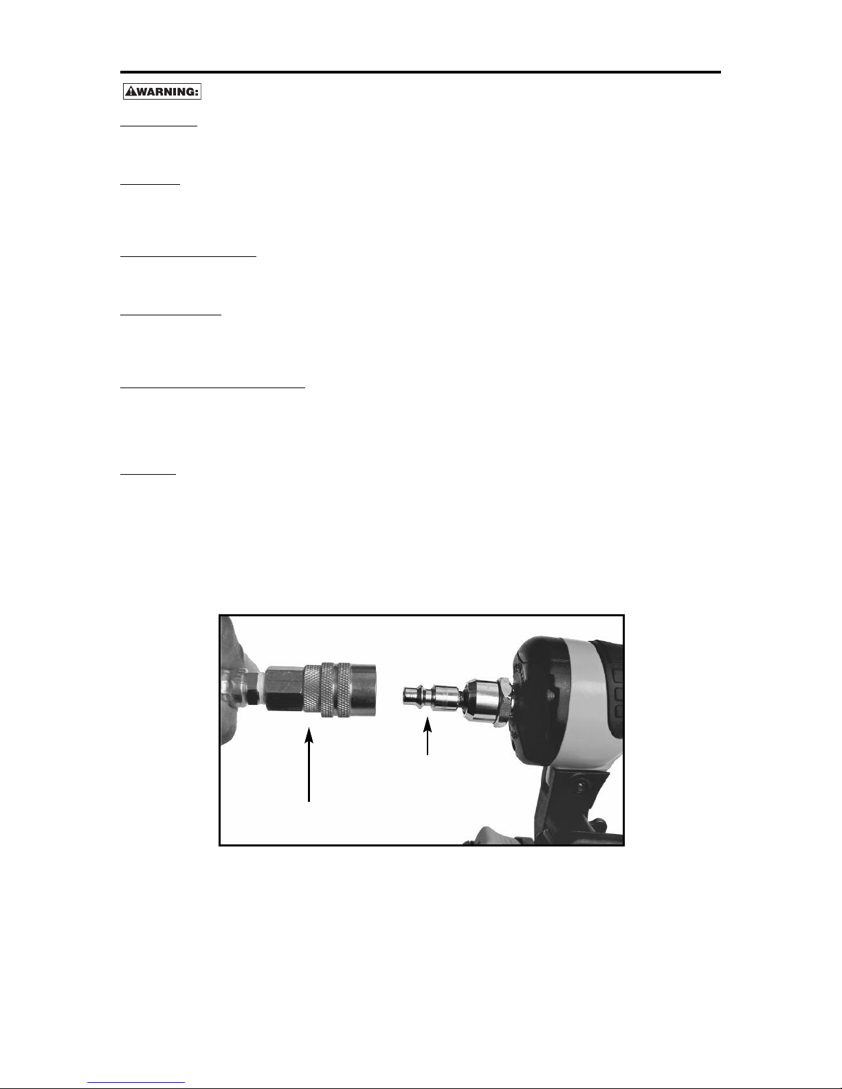
Quick Connect Plug
Quick Disconnect Plug
6
AIR SUPPLY AND CONNECTIONS
D
o not use oxygen, combustible gases, or bottled gases as a power source for this tool as
tool may explode, possibly causing injury.
FITTINGS:
Install a male plug on the tool which is free flowing and which will release air pressure from the tool when
d
isconnected from the supply source.
HOSES:
Air hoses should have a minimum of 150 p.s.i. (10.6 kg/cm2) working pressure rating or 150 percent of the
m
aximum pressure that could be produced in the air system. The supply hose should contain a fitting that will
provide “quick disconnecting” from the male plug on the tool.
SUPPLY SOURCE:
U
se only clean regulated compressed air as a power source for this tool. NEVER USE OXYGEN, COMBUSTIBLE
GASES, OR BOTTLED GASES, AS A POWER SOURCE FOR THIS TOOL AS TOOL MAY EXPLODE.
REGULATOR:
A pressure regulator with an operating pressure of 0 - 125 p.s.i. (0 - 8.79 kg/cm2) is required to control the
operating pressure for safe operation of this tool. Do not connect this tool to air pressure which can potentially
exceed 200 p.s.i. (14 kg/cm
2
) as tool may fracture or burst, possibly causing injury.
OPERATING PRESSURE:
Do not exceed recommended maximum operating pressure as tool wear will be greatly increased. The air
supply must be capable of maintaining the operating pressure at the tool. Pressure drops in the air supply can
reduce the tool’s driving power. Refer to “TOOL SPECIFICATIONS” for setting the correct operating pressure
for the tool.
FILTER:
Dirt and water in the air supply are major causes of wear in pneumatic tools. A filter will help to get the best
performance and minimum wear from the tool. The filter must have adequate flow capacity for the specific
installation. The filter has to be kept clean to be effective in providing clean compressed air to the tool. Consult
the manufacturer’s instructions on proper maintenance of your filter. A dirty and clogged filter will cause a
pressure drop which will reduce the tool’s performance.
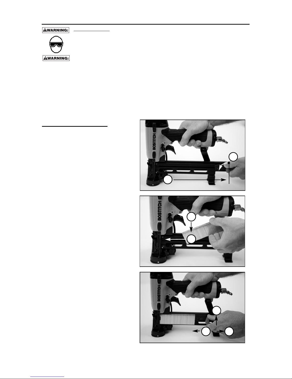
Loading the Staples:
1. Pull the pusher all the way back.
2. Allow the pusher to rotate down into
notch in magazine.
3. Load the staples.
4. Slide the staples all the way forward.
5. Pull back on the pusher.
6. Allow pusher to rotate up out of notch
in magazine.
7. Allow pusher to slide foreword in
contact with the staples.
7
EYE PROTECTION which conforms to ANSI specifications and provides protection against
flying particles both from the FRONT and SIDE should ALWAYS be worn by the operator
and others in the work area when loading, operating or servicing this tool. Eye protection
is required to guard against flying fasteners and debris, which could cause severe eye
injury.
The employer and/or user must ensure that proper eye protection is worn. Eye protection
equipment must conform to the requirements of the American National Standards Institute,
A
NSI Z87.1 and provide both frontal and side protection. NOTE: Non-side shielded
s
pectacles and face shields alone do not provide adequate protection.
TO PREVENT ACCIDENTAL INJURIES:
• Never place a hand or any other part of the body in nail discharge area of tool while the
a
ir supply is connected.
• Never point the tool at anyone else.
• Never engage in horseplay.
•
Never pull the trigger unless nose is directed at the work.
• Always handle the tool with care.
• Do not pull the trigger or depress the trip mechanism while loading the tool.
LOADING STAPLES
1
2
3
4
5
6
7
8
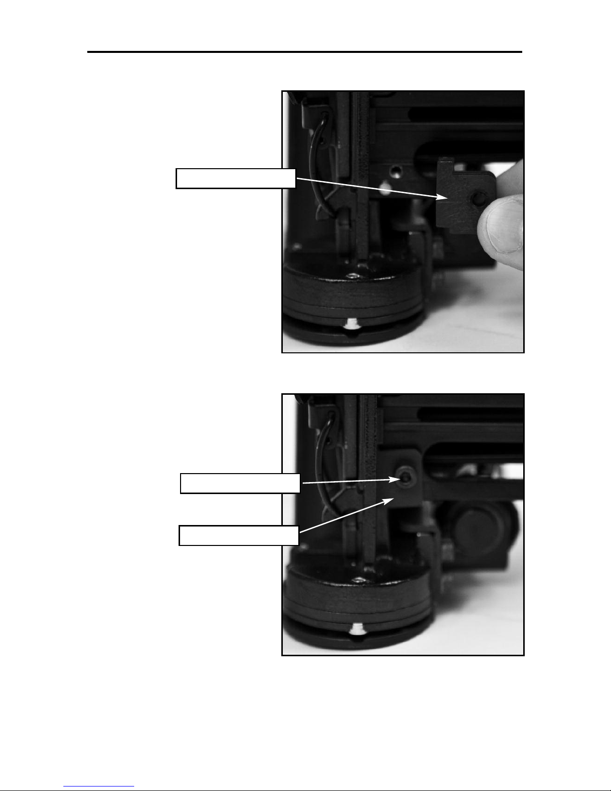
1. Place the Short Staple Guide on
the tool magazine.
INSTALLING THE SHORT STAPLE GUIDE (OPTIONAL)
NOTE: Only use the Short Staple Guide to drive staples from 1/2”to 3/4” long.
2. Use the provided screw
(MSC4070-8) to attach the
Short Staple Guide to the
magazine.
Screw (MSC4070-8)
Short Staple Guide
Short Staple Guide
9
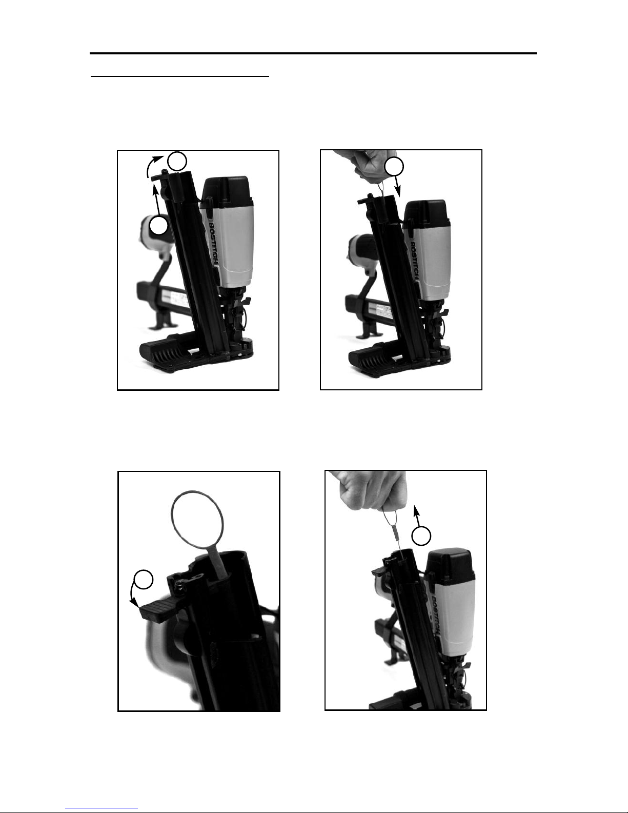
LOADING CAPS
Loading the Plastic Disks:
1. Pull up on the pusher for the plastic disks.
2. Rotate the pusher out of the magazine.
3. Load the plastic disks (held together on a plastic pull string).
4. Rotate the pusher back into the magazine.
5. Pull up and completely remove the plastic pull string.
1
2
3
4
5
10
DIAL-A-DEPTH™ FASTENER CONTROL ADJUSTMENT
T
he DIAL-A-DEPTH™ Fastener control adjustment feature provides close
control of the fastener drive depth: from flush with the work surface to shallow
or deep countersink.
F
irst set the air pressure for consistent drive in the specific work as described
o
n page 4, then use the DIAL-A-DEPTH™ fastener control adjustment to give
the desired depth of drive.
IN ADDITION TO THE OTHER WARNINGS CONTAINED IN THIS
MANUAL OBSERVE THE FOLLOWING FOR SAFE OPERATION
• Use the BOSTITCH pneumatic tool only for the purpose for which it was designed.
• Never use this tool in a manner that could cause a fastener to be directed toward the user
or others in the work area.
• Do not use the tool as a hammer.
• Always carry the tool by the handle. Never carry the tool by the air hose.
• Do not alter or modify this tool from the original design or function without approval from
BOSTITCH, INC.
• Always be aware that misuse and improper handling of this tool can cause injury to
yourself and others.
• Never clamp or tape the trigger or contact trip in an actuated position.
• Never leave a tool unattended with the air hose attached.
• Do not operate this tool if it does not contain a legibleWARNING LABEL.
• Do not continue to use a tool that leaks air or does not function properly. Notify your nearest
Bostitch representative if your tool continues to experience functional problems.
Dial-A-DepthTMFastener Control Adjustment
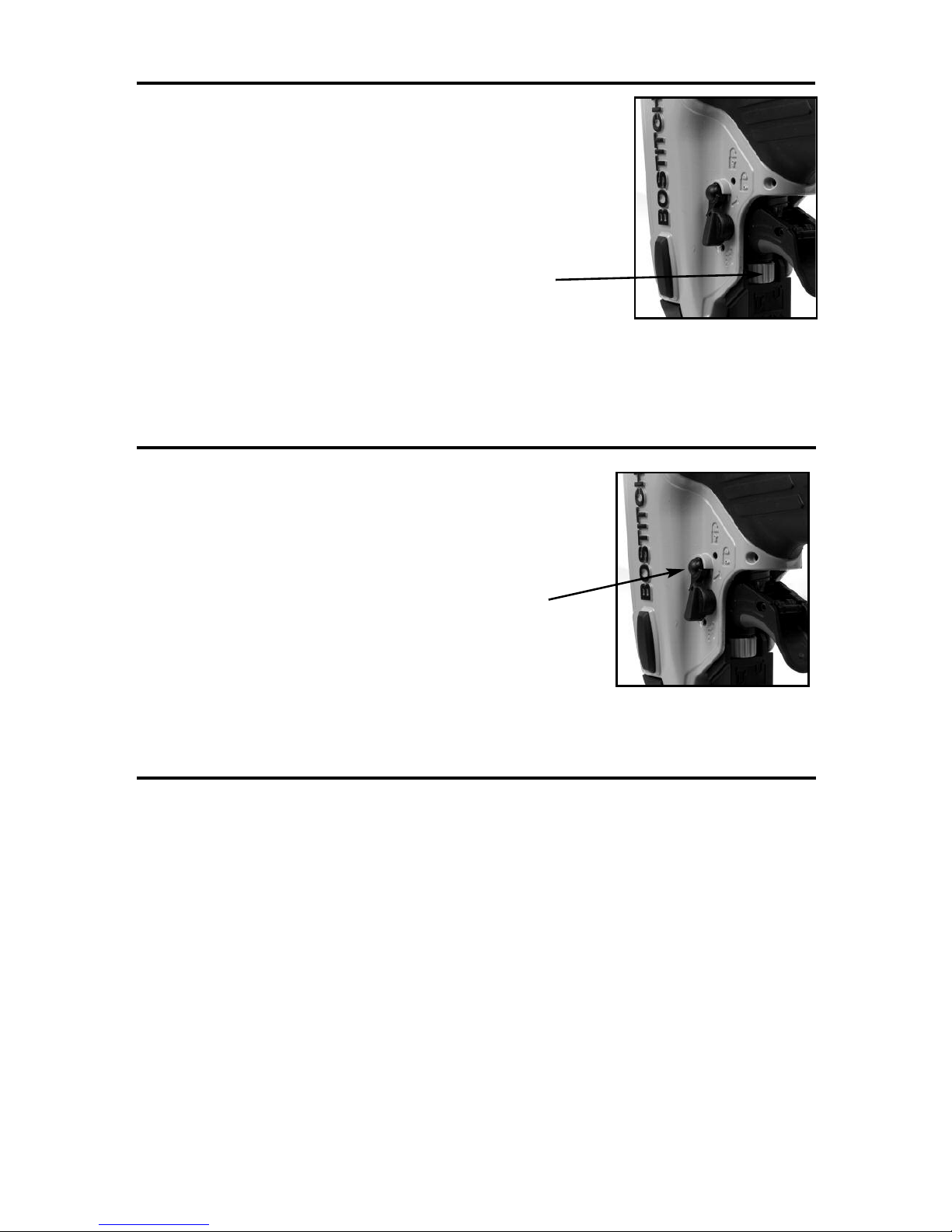
TRIGGER LOCKOUT CONTROL
The trigger lockout control feature on BOSTITCH pneumatic tools provides
a trigger lock feature for added safety control. Push the lockout control
button in or out to activate or lock the tool trigger.
Trigger Lockout Control Button

TOOL OPERATION CHECK
C
AUTION:Remove all fasteners from tool before performing tool operation check.
1. CONTACT TRIP OPERATION:
A. With finger off the trigger, press the contact trip against the work surface.
THE TOOL MUST NOT CYCLE.
B. Hold the tool off the work surface, and pull the trigger.
T
HE TOOL MUST NOT CYCLE.
C
. With the tool off the work surface, pull the trigger. Press the contact trip against the work surface.
T
HE TOOL MUST CYCLE.
D
. Without touching the trigger, press the contact trip against the work surface, then pull the trigger.
T
HE TOOL MUST CYCLE.
2. SEQUENTIAL TRIP OPERATION:
A. Press the contact trip against the work surface, without touching the trigger.
THE TOOL MUST NOT CYCLE.
B. Hold the tool off the work surface and pull the trigger.
THE TOOL MUST NOT CYCLE.
Release the trigger. The trigger must return to the trigger stop on the frame.
C. Pull the trigger and press the contact trip against the work surface.
THE TOOL MUST NOT CYCLE.
D. With finger off the trigger, press the contact trip against the work surface. Pull the trigger.
THE TOOL MUST CYCLE.
MAINTAINING THE PNEUMATIC TOOL
When working on air tools, note the warnings in this manual and use extra care
evaluating problem tools.
REPLACEMENT PARTS:
BOSTITCH replacement parts are recommended. Do not use modified parts or parts which will not give
equivalent performance to the original equipment.
ASSEMBLY PROCEDURE FOR SEALS:
When repairing a tool, make sure the internal parts are clean and lubricated. Use MAGNALUBE or
equivalent on all “O”-rings. Coat each “O”-ring with MAGNALUBE before assembling. Use a small amount of
oil on all moving surfaces and pivots. After reassembly add a few drops of Bostitch air tool lubricant through
the air line fitting before testing.
AIR SUPPLY-PRESSURE AND VOLUME:
Air volume is as important as air pressure. The air volume supplied to the tool may be inadequate because
of undersize fittings and hoses, or from the effects of dirt and water in the system. Restricted air flow will
prevent the tool from receiving an adequate volume of air, even though the pressure reading is high. The
results will be slow operation, misfeeds or reduced driving power. Before evaluating tool problems for these
symptoms, trace the air supply from the tool to the supply source for restrictive connectors, swivel fittings,
low points containing water and anything else that would prevent full volume flow of air to the tool.
11

12
MAINTENANCE CHECKLIST
Maintenance Benefit Procedure Service Interval
I
nspect trigger performanceEnsure trigger system is in
p
roper working order
R
efer to Tool Operation
C
heck section in this manual
D
aily
Drain condensation from air
compressor tanks and air
filters (if present)
Prevents accumulation of
moisture that can impede tool
performance
Open drain cock on tanks
and air filters and drain all
condensate
Daily
Clean magazine assembly Prevents accumulation of
d
ebris that could cause a jam
Blowcleanwith compressedair Daily
Clean nose assembly Prevents accumulation of
debris that could cause a jam
Blowcleanwith compressedair Daily
Ensure all fasteners remain
t
ight
Prevent loose parts Tighten all fasteners with
a
ppropriately sized hex
wrench
Weekly
Check/clean air inlet air filter Maintains proper air flow to
engine for peak performance.
Remove end cap and use
compressed air blow gun to
blow filter clean. Replace filter
as required.
25,000 Fasteners, or monthly
- if used in dusty location
Replace no-mar tip Prevents marks in softwood
applications
Removeworn no-mar tip and
replace witha new tip(a spare tip
islocatedon the magazine)
25,000 Fasteners
Replace swivel air fitting Maintains proper air flow to
engine for peak performance
Remove worn swivel air fitting
and replace with new swivel
fitting
50,000 Fasteners
Replace piston/driver
assembly
Maintains consistent drive
quality
Refer to replacement part kit
instructions
150,000 Fasteners
Replace O-rings Maintains engine for peak
performance
Refer to replacement part kit
instructions
250,000 Fasteners
Replace bumper Maintains engine for peak
performance
Refer to replacement part kit
instructions
250,000 Fasteners
Replace headvalve Maintains engine for peak
performance
Refer to replacement part kit
instructions
250,000 Fasteners
Replace engine cylinder Maintains engine for peak
performance
Refer to replacement part kit
instructions
500,000 Fasteners

13
TROUBLESHOOTING
PROBLEM CAUSE CORRECTION
Trigger valve housing leaks air O-ring cut or cracked . . . . . . . . . . . . . . . . . . . .Replace O-ring
T
rigger valve stem leaks air O-ring/seals cut or cracked . . . . . . . . . . . . . .Replace trigger valve assembly
Frame/nose leaks air O-ring or gasket is cut or cracked . . . . . . . . .Replace O-ring or gasket
B
umper cracked/worn . . . . . . . . . . . . . . . . . . .Replace bumper
F
rame/cap leaks air Damaged gasket or seal . . . . . . . . . . . . . . . . .Replace gasket or seal
Cracked/worn head valve . . . . . . . . . . . . . . .Replace head valve
Loose cap screws . . . . . . . . . . . . . . . . . . . . . . .Tighten and recheck
Failure to cycle Air supply restriction . . . . . . . . . . . . . . . . . . . .Check air supply equipment
Worn head valve . . . . . . . . . . . . . . . . . . . . . . .Replace head valve
B
roken cylinder cap spring . . . . . . . . . . . . . . .Replace cylinder cap spring
Head valve stuck in cap . . . . . . . . . . . . . . . . . .Disassemble / Check / Lubricate
Lack of power; slow to cycle Broken cylinder cap spring . . . . . . . . . . . . . . .Replace cap spring
Rings/seals cut or cracked . . . . . . . . . . . . . . .Replace rings/seals
Exhaust blocked . . . . . . . . . . . . . . . . . . . . . . . .Check bumper, head valve spring
Trigger assembly worn/leaks . . . . . . . . . . . . .Replace trigger assembly
Dirt/tar build up on driver . . . . . . . . . . . . . . . .Disassemble nose/driver to clean
Cylinder sleeve not seated correctly
on bottom bumper . . . . . . . . . . . . . . . . . . . . . . .Disassemble to correct
Air pressure too low . . . . . . . . . . . . . . . . . . . . .Check air supply equipment
Clogged air filter . . . . . . . . . . . . . . . . . . . . . . . .Clean or replace air filter
Skipping fasteners;
intermittent feed Worn bumper . . . . . . . . . . . . . . . . . . . . . . . . . . .Replace bumper
Tar/dirt in driver channel . . . . . . . . . . . . . . . . .Disassemble and clean nose and driver
Air restriction/inadequate air flow through
quick disconnect socket and plug . . . . . . . . .Replace quick disconnect fittings
Worn piston ring . . . . . . . . . . . . . . . . . . . . . . . .Replace ring, check driver
Damaged pusher spring . . . . . . . . . . . . . . . . . .Replace spring
Low air pressure . . . . . . . . . . . . . . . . . . . . . . . .Check air supply system to tool
Loose magazine nose screws . . . . . . . . . . . .Tighten all screws
Fasteners too short for tool . . . . . . . . . . . . . . .Use only recommended fasteners
Bent fasteners . . . . . . . . . . . . . . . . . . . . . . . . . .Discontinue using these fasteners
Wrong size fasteners . . . . . . . . . . . . . . . . . . . .Use only recommended fasteners
Leaking head cap gasket . . . . . . . . . . . . . . . . .Tighten screws/replace gasket
Trigger valve O-ring cut/worn . . . . . . . . . . . . .Replace O-ring
Broken/chipped driver . . . . . . . . . . . . . . . . . . .Replace driver (check piston ring)
Dry/dirty magazine . . . . . . . . . . . . . . . . . . . . . .Clean/lubricate use BOSTITCH Air Tool Lubricant
Worn magazine . . . . . . . . . . . . . . . . . . . . . . . . .Replace magazine
Clogged air filter . . . . . . . . . . . . . . . . . . . . . . . .Clean or replace air filter
Fasteners jam in tool Driver channel worn . . . . . . . . . . . . . . . . . . . . .Replace nose/check door
Wrong size fasteners . . . . . . . . . . . . . . . . . . . .Use only recommended fasteners
Bent fasteners . . . . . . . . . . . . . . . . . . . . . . . . . .Discontinue using these fasteners
Loose magazine/nose screws . . . . . . . . . . . .Tighten all screws
Broken/chipped driver . . . . . . . . . . . . . . . . . . .Replace driver
14
AVAILABLE ACCESSORIES
BT55/SX38-RK
BT1855/SX1838 REBUILD KIT
SL5035 SERIES STAPLES
18 GAUGE 5/16” (8mm) CROWN
TVA-15
BT1855/SX1838
TRIGGER VALVE KIT
SB-CAPS
BOSTITCH 1” PLASTIC CAPS
CAPPAK-1M
1,000 Count Staple/Cap Package
CAPPAK-5M
5,000 Count Staple/Cap Package
 Loading...