

Page 1
BEFORE OPERATING THIS TOOL, ALL OPERATORS SHOULD STUDY THIS MANUAL
TO UNDERSTAND AND FOLLOW THE SAFETY WARNINGS AND INSTRUCTIONS.
KEEP THESE INSTRUCTIONS WITH THE TOOL FOR FUTURE REFERENCE. IF YOU
HAVE ANY QUESTIONS, CONTACT YOUR BOSTITCH REPRESENTATIVE OR
DISTRIBUTOR.
ANTES DE OPERAR ESTA HERRAMIENTA, TODOS LOS OPERADORES DEBERÁN
ESTUDIAR ESTE MANUAL PARA PODER COMPRENDER Y SEGUIR LAS
ADVERTENCIAS SOBRE SEGURIDAD Y LAS INSTRUCCIONES. MANTENGA ESTAS
INSTRUCCIONES CON LA HERRAMIENTA PARA FUTURA REFERENCIA, SI TIENE
ALGUNADUDA, COMUNÍQUESE CON SU REPRESENTANTE DE BOSTITCH O CON SU
DISTRIBUIDOR.
LIRE ATTENTIVEMENT LE PRÉSENT MANUEL AVANT D’UTILISER L’APPAREIL.
PRÉTER UNE ATTENTION TOUTE PARTICULIÈRE AUX CONSIGNES DE SÉCURITÉ ET
AUX AVERTISSEMENTS. GARDER CE MANUEL AVEC L’OUTIL POUR FUTUR
RÉFÉRENCE. SI VOUS AVEZ DES QUESTIONS, CONTACTEZ VOTRE REPRÉSENTANT
OU VOTRE CONCESSIONNAIRE BOSTITCH.
OPERATION and MAINTENANCE MANUAL
MANUAL DE OPERACIÓN Y DE MANTENIMIENTO
MANUEL D’INSTRUCTIONS ET D’ENTRETIEN
SB-150SLBC
BOSTITCH CAP STAPLER
CONJUNTO DE GRAPADORA DE SOMBRERETES BOSTITCH
NÉCESSAIRE D’AGRAFEUSE DE CAPUCHON BOSTITCH
STANLEY FASTENING SYSTEMS L.P.
159832REVC 10/05
Page 2
INTRODUCTION
The Bostitch SB150SLBC is a precision-built tool, designed for high speed, high volume fastening. These
tools will deliver efficient, dependable service when used correctly and with care. As with any fine tool,
for best performance the manufacturer’s instructions must be followed. Please study this manual before
operating the tool and understand the safety warnings and cautions. The instructions on installation,
operation and maintenance should be read carefully, and the manual kept for reference. NOTE:
Additional safety measures may be required because of your particular application of the tool. If you have
any questions concerning the tool and its use call Bostitch Customer Service at 1-800-556-6696 or write
to: Bostitch Customer Service, Briggs Drive, East Greenwich, RI 02818. You may also consult
www.bostitch.com
INDEX
Safety Instructions . . . . . . . . . . . . . . . . . . . . . . . . . . . . . . . . . . . 3
Tool Specifications . . . . . . . . . . . . . . . . . . . . . . . . . . . . . . . . . . . 4
Operation . . . . . . . . . . . . . . . . . . . . . . . . . . . . . . . . . . . . . . . . . . 4
Air Supply and Connections . . . . . . . . . . . . . . . . . . . . . . . . . . . . 5
Lubrication . . . . . . . . . . . . . . . . . . . . . . . . . . . . . . . . . . . . . . . . . 5
Loading the Staples and Button Caps . . . . . . . . . . . . . . . . . . 6, 7
Depth Control, Jam Clearing, Directional Exhaust . . . . . . . . . . . 8
Tool Operation . . . . . . . . . . . . . . . . . . . . . . . . . . . . . . . . . . . . 10
Tool Operation Check . . . . . . . . . . . . . . . . . . . . . . . . . . . . . . . . 11
Maintaining the Pneumatic Tool . . . . . . . . . . . . . . . . . . . . . . . . 11
Trouble Shooting . . . . . . . . . . . . . . . . . . . . . . . . . . . . . . . . . . 12
NOTE:
Bostitch tools have been engineered to provide excellent customer satisfaction and are designed to achieve
maximum performance when used with precision Bostitch fasteners engineered to the same exacting
standards. Bostitch cannot assume responsibility for product performance if our tools are used
with fasteners or accessories not meeting the specific requirements established for genuine Bostitch
nails, staples and accessories.
LIMITED WARRANTY — U.S. and Canada Only
Effective December 1, 2005 Bostitch, L.P. warrants to the original retail purchaser that the product purchased is
free from defects in material and workmanship, and agrees to repair or replace, at Bostitch’s option, any
defective Bostitch branded pneumatic stapler or nailer for a period of seven (7) years from date of purchase (one
(1) year from the date of purchase for compressors and tools used in production applications). Warranty is not
transferable. Proof of purchase date required. This warranty covers only damage resulting from defects in
material or workmanship; it does not cover conditions or malfunctions resulting from normal wear, neglect,
abuse, accident or repairs attempted or made by other than our national repair center or authorized warranty
service centers. Driver blades, bumpers, o-rings, pistons and piston rings are considered normally wearing parts.
For optimal performance of your Bostitch tool always use genuine Bostitch fasteners and replacement parts.
THIS WARRANTY IS IN LIEU OF ALL OTHER WARRANTIES, EXPRESS OR IMPLIED, INCLUDING BUT
NOT LIMITED T O THE IMPLIED W ARRANTIES OF MERCHANTABILITYOR FITNESS FOR APARTICULAR
PURPOSE. BOSTITCH SHALLNOT BE LIABLE FOR ANYINCIDENTALOR CONSEQUENTIAL DAMAGES.
Some states and countries do not allow limitations on how long an implied warranty lasts, or the exclusion or
limitation of incidental or consequential damages, so the above limitations or exclusions may not apply to you.
This warranty gives you specific legal rights, and you may also have other rights which vary from state to state
and country to country .
To obtain warranty service in the U.S. return the product, together with proof of purchase, to the U.S. Bostitch
National or Regional Independent Authorized Warranty Service Center. In the U.S. you may call us at 1-800556-6696 or visit www.BOSTITCH.com for the location most convenient for you. In Canada please call us at
800-567-7705 or visit www.BOSTITCH.com
2
Page 3
3
SAFETY INSTRUCTIONS
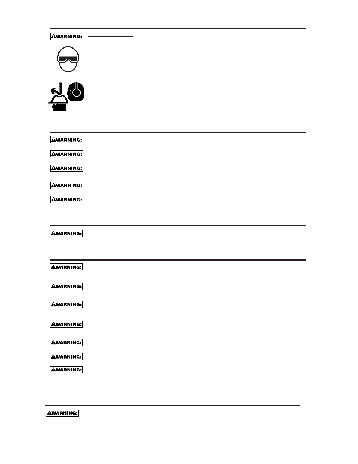
EYE PROTECTION which conforms to ANSI specifications and provides protection against
flying particles both from the FRONT and SIDE should AL W AYS be worn by the operator and
others in the work area when connecting to air supply, loading, operating or servicing this
tool. Eye protection is required to guard against flying fasteners and debris, which could
cause severe eye injury.
The employer and/or user must ensure that proper eye protection is worn. Eye protection
equipment must conform to the requirements of the American National Standards Institute,
ANSI Z87.1 and provide both frontal and side protection. NOTE: Non-side shielded
spectacles and face shields alone do not provide adequate protection.
CAUTION:
Additional Safety Protection will be required in some environments. For
example, the working area may include exposure to noise level which can lead to hearing
damage. The employer and user must ensure that any necessary hearing protection is
provided and used by the operator and others in the work area. Some environments will
require the use of head protection equipment. When required, the employer and user must
ensure that head protection conforming to ANSI Z89.1 is used.
AIR SUPPLY AND CONNECTIONS
Do not use oxygen, combustible gases, or bottled gases as a power source for this tool as
tool may explode, possibly causing injury.
Do not use supply sources which can potentially exceed 200 P.S.I.G. as tool may burst,
possibly causing injury.
The connector on the tool must not hold pressure when air supply is disconnected. If a
wrong fitting is used, the tool can remain charged with air after disconnecting and thus will
be able to drive a fastener even after the air line is disconnected possibly causing injury.
Do not pull trigger or depress contact arm while connected to the air supply as the tool may
cycle, possibly causing injury.
Always disconnect air supply: 1.) Before making adjustments; 2.) When servicing the tool;
3.) When clearing a jam; 4.) When tool is not in use; 5.) When moving to a different work
area, as accidental actuation may occur, possibly causing injury.
LOADING TOOL
When loading tool: 1.) Never place a hand or any part of body in fastener discharge area of
tool; 2.) Never point tool at anyone; 3.) Do not pull the trigger or depress the trip as
accidental actuation may occur, possibly causing injury.
OPERATION
Always handle the tool with care: 1.) Never engage in horseplay; 2.) Never pull the trigger
unless nose is directed toward the work; 3.) Keep others a safe distance from the tool while
tool is in operation as accidental actuation may occur, possibly causing injury.
The operator must not hold the trigger pulled on contact arm tools except during fastening
operation as serious injury could result if the trip accidentally contacted someone or
something, causing the tool to cycle.
Keep hands and body away from the discharge area of the tool. A contact arm tool may
bounce from the recoil of driving a fastener and an unwanted second fastener may be
driven possibly causing injury.
Check operation of the contact arm mechanism frequently. Do not use the tool if the arm
is not working correctly as accidental driving of a fastener may result. Do not interfere with
the proper operation of the contact arm mechanism.
Do not drive fasteners on top of other fasteners or with the tool at an overly steep angle as
this may cause deflection of fasteners which could cause injury.
Do not drive fasteners close to the edge of the work piece as the wood may split, allowing
the fastener to be deflected possibly causing injury.
This nailer produces SPARKS during operation. NEVER use the nailer near flammable
substances, gases or vapors including lacquer, paint, benzine, thinner, gasoline, adhesives,
mastics, glues or any other material that is -- or the vapors, fumes or byproducts of which are -flammable, combustible or explosive. Using the nailer in any such environment could cause an
EXPLOSION resulting in personal injury or death to user and bystanders.
MAINTAINING THE TOOL
When working on air tools note the warnings in this manual and use extra care when
evaluating problem tools.
Page 4
4
TOOL SPECIFICATIONS
All screws and nuts are metric
MODEL
TOOL
LENGTH HEIGHT WIDTH WEIGHT
ACTUATION
SB150SLBC-1 Contact Trip 11.25” (285.8mm) 10.63” (270.0mm) 6.38” (162.1mm) 4.7 lb (2.1 kg)
SB150SLBC-2 Sequential Trip 11.25” (285.8mm) 10.63” (270.0mm) 6.38” (162.1mm) 4.7 lb (2.1 kg)
BOSTITCH offers two types of Operation for this series tool.
CONT
ACT TRIP
The common operating procedure on “Contact Trip” tools is for the operator to contact the work to
actuate the trip mechanism while keeping the trigger pulled, thus driving a fastener each time the work
is contacted. This will allow rapid fastener placement in many industrial applications.
All pneumatic tools are subject to recoil when driving fasteners. The tool may bounce, releasing the
trip, and if unintentionally allowed to recontact the work surface with the trigger still actuated (finger still
holding trigger pulled) an unwanted second fastener will be driven.
SEQUENTIAL TRIP
The Sequential Trip requires the operator to hold the tool against the work before pulling the trigger. This
makes accurate fastener placement easier, for instance on finish applications.
The Sequential Trip allows exact fastener location without the possibility of driving a second fastener on
recoil, as described under “Contact Trip”.
The Sequential Trip Tool has a positive safety advantage because it will not accidentally drive a fastener if
the tool is contacted against the work – or anything else – while the operator is holding the trigger pulled.
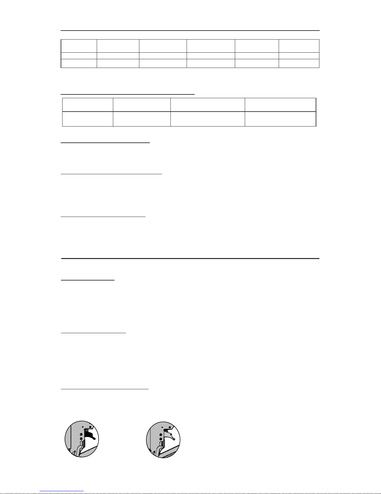
MODEL IDENTIFICATION:
Refer to Operation Instructions on page 8 before proceeding to use this tool.
CONTACT TRIP SEQUENTIAL TRIP
Identified by: Identified by:
BLACK TRIGGER GRAY TRIGGER
OPERATION
F
ASTENER SPECIFICATIONS:
TOOL AIR FITTING:
This tool uses a free-flow connector plug, 1/4 N.P.T. The inside diameter should be .200” (5mm) or larger.
The fitting must be capable of discharging tool air pressure when disconnected from the air supply.
OPERATING PRESSURE:
70 to 100 p.s.i.g. (4.8 to 6.9 Bar ). Select the operating pressure within this range for best fastener
performance.
DO NOT EXCEED THE RECOMMENDED OPERA TING PRESSURE.
AIR CONSUMPTION:
The SB150SLBC requires 5.63 cubic feet per minute (.16 cubic meters) of free air to operate at the rate of
100 staples per minute, at 90 p.s.i. (6.2 Bar). Take the actual rate at which the tool will be run to determine the
amount of air required. For instance, if your fastener usage averages 50 staples per minute, you need 50% of
the tool’s c.f.m. which is required to operate the tool at 100 staples per minute.
STAPLE SERIES CROWN WIDTH WIRE GAUGE FASTENER RANGE
SL5035 5/16” (8.0mm) .050 x .035 (1.27 x 0.89mm) 3/4”-11/2” (19mm-38mm)
Cap Capacity: 100 Caps
Staple Capacity: 150 Staples
Page 5

AIR SUPPLY AND CONNECTIONS
Do not use oxygen, combustible gases, or bottled gases as a power source for this tool as tool
may explode, possibly causing injury.
FITTINGS:
Install a male plug on the tool which is free flowing and which will release air pressure
from the tool when disconnected from the supply source.
HOSES:
Air hoses should have a minimum of 150 p.s.i. (10.6 kg/cm2) working pressure rating or
150 percent of the maximum pressure that could be produced in the air system. The
supply hose should contain a fitting that will provide “quick disconnecting” from the male
plug on the tool.
SUPPLY SOURCE:
Use only clean regulated compressed air as a power source for this tool. NEVER USE OXYGEN,
COMBUSTIBLE GASES, OR BOTTLED GASES, AS APOWER SOURCE FOR THIS TOOL AS
TOOL MAY EXPLODE.
REGULATOR:
A pressure regulator with an operating pressure of 0 - 125 p.s.i. (0 - 8.79 KG/CM2) is required to control
the operating pressure for safe operation of this tool. Do not connect this tool to air pressure which can
potentially exceed 200 p.s.i. (14 KG/CM
2
)as tool may fracture or burst, possibly causing injury.
OPERATING PRESSURE:
Do not exceed recommended maximum operating pressure as tool wear will be greatly increased. The
air supply must be capable of maintaining the operating pressure at the tool. Pressure drops in the air
supply can reduce the tool’s driving power. Refer to “TOOL SPECIFICATIONS” for setting the correct
operating pressure for the tool.
FIL
TER:
Dirt and water in the air supply are major causes of wear in pneumatic tools. Afilter will help to get the
best performance and minimum wear from the tool. The filter must have adequate flow capacity for the
specific installation. The filter has to be kept clean to be effective in providing clean compressed air to
the tool. Consult the manufacturer’s instructions on proper maintenance of your filter. A dirty and
clogged filter will cause a pressure drop which will reduce the tool’s performance.
Frequent, but not excessive, lubrication is required for best performance. Oil added through the air line
connection will lubricate the internal parts. Use BOSTITCH Air Tool Lubricant, Renolin HPL 46, or equivalent.
Do not use detergent oil or additives as these lubricants will cause accelerated wear to the seals and bumpers
in the tool, resulting in poor tool performance and frequent tool maintenance.
If no airline lubricator is used, add oil during use into the air fitting on the tool once or twice a day. Only a few
drops of oil at a time is necessary. Too much oil will only collect inside the tool and will be noticeable in the
exhaust cycle.
COLD WEATHER OPERATION:
For cold weather operation, near and below freezing, the moisture in the air line may freeze and prevent tool
operation. We recommend the use of BOSTITCH WINTER FORMULA air tool lubricant or permanent
antifreeze (ethylene glycol) as a cold weather lubricant.
CAUTION:
Do not store tools in a cold weather environment to prevent frost or ice formation on the
tools operating valves and mechanisms that could cause tool failure.
NOTE:
Some commercial air line drying liquids are harmful to “O”-rings and seals – do not use these
low temperature air dryers without checking compatibility.
5
LUBRICATION
Page 6

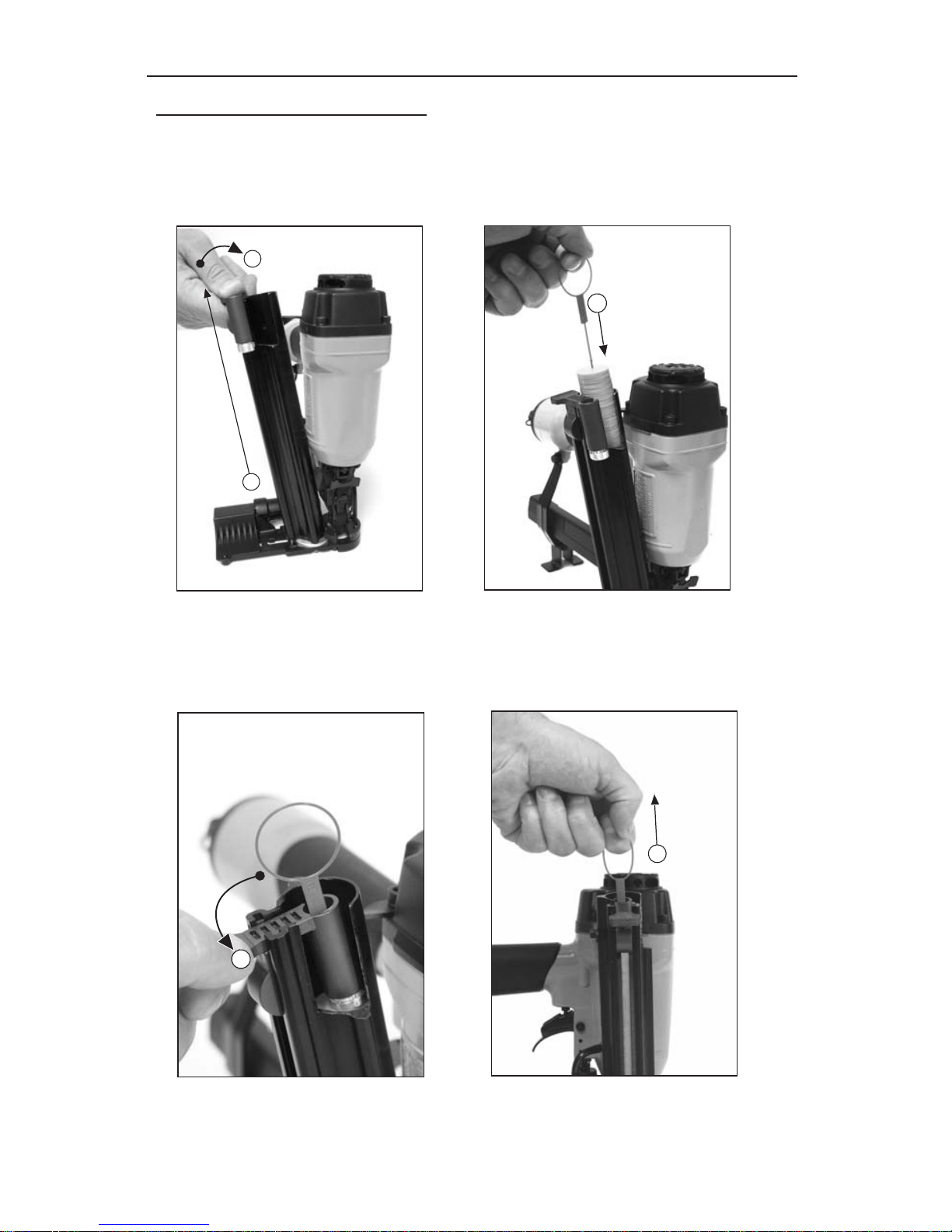
Loading the Staples:
1. Pull the pusher all the way back.
2. Allow the pusher to rotate down into
notch in magazine.
3. Load the staples.
4. Slide the staples all the way forward.
5. Pull back on the pusher.
6. Allow pusher to rotate up out of
notch in magazine.
7. Allow pusher to slide foreword in
contact with the staples.
EYE PROTECTION which conforms to ANSI specifications and provides protection
against flying particles both from the FRONT and SIDE should ALWAYS be worn by
the operator and others in the work area when loading, operating or servicing this
tool. Eye protection is required to guard against flying fasteners and debris, which
could cause severe eye injury.
The employer and/or user must ensure that proper eye protection is worn. Eye
protection equipment must conform to the requirements of the American National
Standards Institute, ANSI Z87.1-1989 (R1998) and provide both frontal and side
protection. NOTE: Non-side shielded spectacles and face shields alone do not
provide adequate protection.
TO PREVENT ACCIDENTAL INJURIES:
• Never place a hand or any other part of the body in nail discharge area of tool while the air supply is connected.
• Never point the tool at anyone else.
• Never engage in horseplay.
• Never pull the trigger unless nose is directed at the work.
• Always handle the tool with care.
• Do not pull the trigger or depress the trip mechanism while loading the tool.
LOADING THE SB150SLBC
6
1
2
4
3
5
6
7
Page 7
7
LOADING THE SB150SLBC
2
1
Loading the Plastic Disks:
1. Pull up on the pusher for the plastic disks.
2. Rotate the pusher out of the magazine.
3. Load the plastic disks (held together on the plastic pull string).
3
4
5
4. Rotate the pusher back into the magazine.
5. Pull up and completely remove the plastic pull string.
Page 8
8
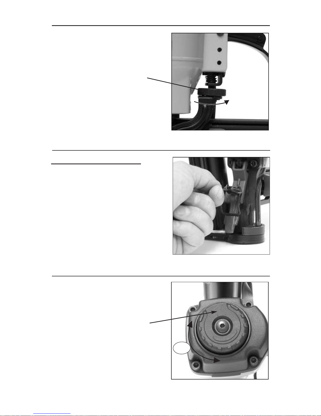
To adjust for a deeper depth of drive,
rotate knob counter clockwise (as
viewed from above).
To adjust for a more shallow drive,
rotate knob clockwise.
FASTENER DEPTH CONTROL ADJUSTMENT
To clear a jammed staple:
1. Disconnect air hose.
2. Pull pusher back to stop staple feeding.
3. Open door in front of nose by
releasing latch.
4. Remove jammed staple.
5. Close door and reconnect latch.
6. Bring pusher forward to restart staple
feeding.
7. Reconnect air hose.
FASTENER JAM CLEARING
The adjustable exhaust deflector can
be rotated to any desired position by
hand without the use of any tools.
DIRECTIONAL EXHAUST DEFLECTOR
360
o
Exhaust Deflector
Deeper
Adjustment Knob
Page 9

9
IN ADDITION TO THE OTHER WARNINGS CONTAINED IN THIS
MANUAL OBSERVE THE FOLLOWING FOR SAFE OPERATION
• Use the BOSTITCH pneumatic tool only for the purpose for which it was designed.
• Never use this tool in a manner that could cause a fastener to be directed toward the user
or others in the work area.
• Do not use the tool as a hammer.
• Always carry the tool by the handle. Never carry the tool by the air hose.
• Do not alter or modify this tool from the original design or function without approval from
BOSTITCH.
• Always be aware that misuse and improper handling of this tool can cause injury to
yourself and others.
• Never clamp or tape the trigger or contact trip in an actuated position.
• Never leave a tool unattended with the air hose attached.
• Do not operate this tool if it does not contain a legible WARNING LABEL.
•Do not continue to use a tool that leaks air or does not function properly. Notify your nearest
BOSTITCH representative if your tool continues to experience functional problems.
Page 10

TOOL OPERATION
EYE PROTECTION which conforms to ANSI specifications and provides
protection against flying particles both from the FRONT and SIDE should
ALWAYS be worn by the operator and others in the work area when loading,
operating or servicing this tool. Eye protection is required to guard against
flying fasteners and debris, which could cause severe eye injury.
The employer and/or user must ensure that proper eye protection is worn.
Eye protection equipment must conform to the requirements of the
American National Standards Institute, ANSI Z87.1-1989 (R1998) and provide
both frontal and side protection. NOTE: Non-side shielded spectacles and
face shields alone do not provide adequate protection.
BEFORE HANDLING OR OPERATING THIS T
OOL:
I. READ AND UNDERSTAND THE WARNINGS CONTAINED IN THIS MANUAL.
II. REFER TO “TOOL SPECIFICATIONS” IN THIS MANUAL TO IDENTIFY THE
OPERATING SYSTEM ON YOUR TOOL.
1. CONTACT TRIP OPERATION:
The CONT ACTTRIP MODEL tool contains a contact trip that operates in conjunction with
the trigger to drive a fastener. There are two methods of operation to drive fasteners with
a contact trip tool.
A. SINGLE FASTENER PLACEMENT: To operate the tool in this manner, first
position the contact trip on the work surface, WITHOUT PULLING THE TRIGGER.
Depress the contact trip until the nose touches the work surface and then pull the
trigger to drive a fastener. Do not press the tool against the work with extra force.
Instead, allow the tool to recoil off the work surface to avoid a second unwanted
fastener. Remove your finger from the trigger after each operation.
B. RAPID FASTENER OPERATION: To operate the tool in this manner, hold the
tool with the contact trip pointing towards but not touching the work surface. Pull
the trigger and then tap the contact trip against the work surface using a bouncing
motion. Each depression of the contact trip will cause a fastener to be driven.
There are three available systems on BOSTITCH pneumatic tools. They are:
1. CONTACT TRIP OPERATION 2. SEQUENTIAL TRIP OPERATION 3.TRIGGER OPERATION
The operator must not hold the trigger pulled on contact trip tools except
during fastening operation, as serious injury could result if the trip
accidentally contacted someone or something, causing the tool to cycle.
Keep hands and body away from the discharge area of the tool. A contact
trip tool may bounce from the recoil of driving a fastener and an unwanted
second fastener may be driven, possibly causing injury .
2. SEQUENTIAL TRIP OPERATION:
The SEQUENTIAL TRIP MODELcontains a contact trip that operates in conjunction with the trigger to
drive a fastener. To operate a sequential trip tool, first position the contact trip on the work surface
WITHOUT PULLING THE TRIGGER. Depress the contact trip and then pull the trigger to drive a
fastener. As long as the contact trip is contacting the work and is held depressed, the tool will drive a
fastener each time the trigger is depressed. If the contact trip is allowed to leave the work surface, the
sequence described above must be repeated to drive another fastener.
3. TRIGGER OPERATION:
The TRIGGER OPERATED tool requires a single action to drive a fastener. Each time the trigger is
pulled the tool will drive a fastener. This model does not have a contact trip and is intended for
use only where a contact trip cannot be used to satisfy the requirements of the application.
10
OPERATION
Page 11

TOOL OPERATION CHECK
CAUTION: Remove all fasteners from tool before performing tool operation check.
1. CONTACT TRIP OPERATION:
A. With finger off the trigger, press the contact trip against the work surface.
THE TOOL MUST NOT CYCLE.
B. Hold the tool off the work surface, and pull the trigger.
THE TOOL MUST NOT CYCLE.
C. With the tool off the work surface, pull the trigger. Press the contact trip against the work surface.
THE TOOL MUST CYCLE.
D. Without touching the trigger, press the contact trip against the work surface, then pull the trigger.
THE TOOL MUST CYCLE.
2. SEQUENTIAL TRIP
OPERATION:
A. Press the contact trip against the work surface, without touching the trigger.
THE TOOL MUST NOT CYCLE.
B. Hold the tool off the work surface and pull the trigger.
THE TOOL MUST NOT CYCLE.
Release the trigger. The trigger must return to the trigger stop on the frame.
C. Pull the trigger and press the contact trip against the work surface.
THE TOOL MUST NOT CYCLE.
D. With finger off the trigger, press the contact trip against the work surface. Pull the trigger.
THE TOOL MUST CYCLE.
3. TRIGGER OPERATED TOOL:
A. With finger off the trigger, hold the tool with a firm grip on the handle.
B. Place the nose of the tool against the work surface.
C. Pull the trigger to drive fastener. Release the trigger and cycle is complete.
CAUTION:
THE TOOL WILL CYCLE EACH TIME THE TRIGGER INTERLOCK AND TRIGGER IS PULLED!
MAINTAINING THE PNEUMATIC TOOL
When working on air tools, note the warnings in this manual and use extra care
evaluating problem tools.
REPLACEMENT PARTS:
BOSTITCH replacement parts are recommended. Do not use modified parts or parts
which will not give equivalent performance to the original equipment.
ASSEMBLY PROCEDURE FOR SEALS:
When repairing a tool, make sure the internal parts are clean and lubricated. Use MAGNALUBE
or equivalent on all “O”-rings. Coat each “O”-ring with MAGNALUBE before assembling. Use a small
amount of oil on all moving surfaces and pivots. After reassembly add a few drops of Bostitch air tool
lubricant through the air line fitting before testing.
AIR SUPPLY-PRESSURE AND VOLUME:
Air volume is as important as air pressure. The air volume supplied to the tool may be inadequate
because of undersize fittings and hoses, or from the effects of dirt and water in the system.
Restricted air flow will prevent the tool from receiving an adequate volume of air, even though the
pressure reading is high. The results will be slow operation, misfeeds or reduced driving power.
Before evaluating tool problems for these symptoms, trace the air supply from the tool to the supply
source for restrictive connectors, swivel fittings, low points containing water and anything else that
would prevent full volume flow of air to the tool.
11
Page 12

Trigger valve housing leaks air O-ring cut or cracked . . . . . . . . . . . . . .Replace O-ring
Trigger valve stem leaks air O-ring/seals cut or cracked . . . . . . . . .Replace trigger valve assembly
Frame/nose leaks air Loose nose screws . . . . . . . . . . . . . . .Tighten and recheck
O-ring or Gasket is cut or cracked . . . .Replace O-ring or gasket
Bumper cracked/worn . . . . . . . . . . . . .Replace bumper
Frame/cap leaks air Damaged gasket or seal . . . . . . . . . . .Replace gasket or seal
Cracked/worn head valve bumper . . . .Replace bumper
Loose cap screws . . . . . . . . . . . . . . . .Tighten and recheck
Failure to cycle Air supply restriction . . . . . . . . . . . . . . .Check air supply equipment
Tool dry, lack of lubrication . . . . . . . . . .Use BOSTITCH Air Tool Lubricant
Worn head valve O-rings . . . . . . . . . . .Replace O-rings
Broken cylinder cap spring . . . . . . . . . .Replace cylinder cap spring
Head valve stuck in cap . . . . . . . . . . . .Disassemble/Check/Lubricate
Lack of power; slow to cycle Tool dry, lacks lubrication . . . . . . . . . . .Use BOSTITCH Air Tool Lubricant
Broken cylinder cap spring . . . . . . . . . .Replace cap spring
O-rings/seals cut or cracked . . . . . . . . .Replace O-rings/seals
Exhaust blocked . . . . . . . . . . . . . . . . .Check bumper, head valve spring, muffler
Trigger assembly worn/leaks . . . . . . . .Replace trigger assembly
Dirt/tar build up on driver . . . . . . . . . . .Disassemble nose/driver to clean
Cylinder sleeve not seated correctly
on bottom bumper . . . . . . . . . . . . . . . .Disassemble to correct
Head valve dry . . . . . . . . . . . . . . . . . . .Disassemble/lubricate
Air pressure too low . . . . . . . . . . . . . . .Check air supply equipment
Skipping fasteners; intermittent feed Worn bumper . . . . . . . . . . . . . . . . . . . .Replace bumper
Tar/dirt in driver channel . . . . . . . . . . . .Disassemble and clean nose and driver
Air restriction/inadequate air flow through
quick disconnect socket and plug . . . . .Replace quick disconnect fittings
Worn piston O-ring . . . . . . . . . . . . . . . .Replace O-ring, check driver
Tool dry, lacks lubrication . . . . . . . . . . .Use BOSTITCH Air Tool Lubricant
Low air pressure . . . . . . . . . . . . . . . . .Check air supply system to tool
Loose magazine nose screws . . . . . . .Tighten all screws
Fasteners too short for tool . . . . . . . . .Use only recommended fasteners
Bent fasteners . . . . . . . . . . . . . . . . . . .Discontinue using these fasteners
Wrong size fasteners . . . . . . . . . . . . . .Use only recommended fasteners
Leaking head cap gasket . . . . . . . . . . .Tighten screws/replace gasket
Trigger valve O-ring cut/worn . . . . . . . .Replace O-ring
Broken/chipped driver . . . . . . . . . . . . .Replace driver (check piston O-ring)
Dry/dirty magazine . . . . . . . . . . . . . . . .Clean/lubricate use BOSTITCH
Air Tool Lubricant
Worn magazine . . . . . . . . . . . . . . . . . .Replace magazine
Fasteners jam in tool Driver channel worn . . . . . . . . . . . . . . .Replace nose/check door
Wrong size fasteners . . . . . . . . . . . . . .Use only recommended fasteners
Bent fasteners . . . . . . . . . . . . . . . . . . .Discontinue using these fasteners
Loose magazine/nose screws . . . . . . .Tighten all screws
Broken/chipped driver . . . . . . . . . . . . .Replace driver
TROUBLE SHOOTING
PROBLEM CAUSE CORRECTION
12
Page 13

13
Page 14

INTRODUCCIÓN
La Bostitch SB150SLBC es una herramienta construida a precisión, diseñada para funcionar a alta
velocidad y con alto volumen. Estas herramientas entregan un servicio eficiente y fiable cuando se usan
correctamente y con cuidado. Al igual que con toda herramienta de calidad, deben seguirse las
instrucciones del fabricante para obtener el óptimo rendimiento. Estudie este manual antes de operar la
herramienta y entender las advertencias y precauciones de seguridad. Deben leerse en detalle las
instrucciones sobre la instalación, operación y mantenimiento, y debe conservarse el manual para
referencia. NOTA: Pueden necesitarse medidas adicionales de seguridad según la aplicación particular
de la herramienta. Si tiene alguna pregunta referente a la herramienta y su uso llame al Servicio a
clientes de Bostitch al 1-800-556-6696 o escriba a: Bostitch Customer Service, Briggs Drive, East
Greenwich, RI 02818. Puede consultar también la página web www.bostitch.com
ÍNDICE
Instrucciones de seguridad . . . . . . . . . . . . . . . . . . . . . . . . . . . 15
Especificaciones de la herramienta . . . . . . . . . . . . . . . . . . . . . 16
Funcionamiento . . . . . . . . . . . . . . . . . . . . . . . . . . . . . . . . . . . . 16
Suministro de aire y conexiones . . . . . . . . . . . . . . . . . . . . . . . . 17
Lubricación. . . . . . . . . . . . . . . . . . . . . . . . . . . . . . . . . . . . . . . . 17
Carga de grapas y sombreretes . . . . . . . . . . . . . . . . . . . . 18, 19
Control de profundidad, eliminación de atascos,
escape direccional . . . . . . . . . . . . . . . . . . . . . . . . . . . . . . . . . . 20
Funcionamiento de la herramienta . . . . . . . . . . . . . . . . . . . . . 22
Revisión funcional de la herramienta. . . . . . . . . . . . . . . . . . . . . 23
Mantenimiento de la herramienta neumática . . . . . . . . . . . . . . 23
Solución de problemas . . . . . . . . . . . . . . . . . . . . . . . . . . . . . . 24
NOTA:
Las herramientas Bostitch se han diseñado para brindar una satisfacción excelente al cliente y lograr máximo
rendimiento al utilizarse con grapas o puntas de precisión Bostitch diseñadas con las mismas normas estrictas.
Bostitch no puede asumir responsabilidad alguna por el rendimiento del producto si se utilizan nuestras
herramientas con clavos, grapas o accesorios que no reúnen los requisitos específicos establecidos para los
clavos, grapas y accesorios genuinos de Bostitch.
GARANTÍA LIMITADA — Sólo EE.UU. y Canadá
A partir del 1 de diciembre de 2005 Bostitch, L.P. garantiza al comprador del comerciante original que el
producto comprado está exento de defectos en material y fabricación, y se compromete a reparar o reemplazar,
a opción de Bostitch, cualquier engrapadora o clavadora neumática defectuosa de marca Bostitch por un
período de siete (7) años desde la fecha de compra (un (1) año de la fecha de compra en el caso de
compresores y herramientas utilizadas en aplicaciones de producción). La garantía no es transferible. Se
requiere presentar evidencia de la fecha de compra. Esta garantía solamente cubre daños resultantes de
defectos en material o fabricación, y no cubre condiciones o desperfectos resultantes del desgaste normal,
negligencia, abuso, accidente o reparaciones intentadas o efectuadas por terceros ajenos a nuestro centro
nacional de reparaciones o a los centros de servicio bajo garantía. Las aspas del impulsor, topes, juntas tóricas,
pistones y aros de pistones se consideran componentes de desgaste normal. Para obtener el rendimiento
óptimo de la herramienta Bostitch siempre use fijaciones y piezas de repuesto genuinas de Bostitch.
ESTA GARANTÍA SUSTITUYE TODA OTRA GARANTÍA, EXPRESA O IMPLÍCITA, INCLUIDAS ENTRE
OTRAS, LAS GARANTÍAS IMPLÍCITAS DE COMERCIABILIDAD O IDONEIDAD PARA UN FIN
PARTICULAR. BOSTITCH NO SERÁ RESPONSABLE DE DAÑOS FORTUITOS O CONSECUENCIALES.
Algunos estados y países no permiten limitaciones a la duración de una garantía implícita ni la exclusión o
limitación de daños fortuitos o consecuenciales, de modo que las limitaciones o exclusiones anteriores pueden
no corresponder a su caso. Esta garantía le concede derechos legales específicos, y usted puede tener
también otros derechos que varían de un estado a otro y de un país a otro.
Para obtener servicio bajo garantía en los EE.UU. devuelva el producto, junto con el comprobante de compra,
al Centro de Servicio bajo Garantía Autorizado Independiente Nacional o Regional de Bostitch en los EE.UU.
Dentro de los EE.UU. usted puede llamarnos al 1-800-556-6696 o visitar www.BOSTITCH.com para ver la
ubicación que más le convenga. En Canadá llámenos al at 800-567-7705 o visite www.BOSTITCH.com.
14
Page 15

15
INSTRUCCIONES DE SEGURIDAD
Cuando el equipo está conectado al suministro de aire, tanto el operador como todas las
personas que se encuentren en el área de trabajo, SIEMPRE deben usar PROTECCIÓN OCULAR
que cumpla las especificaciones ANSI para resguardo contra partículas volantes arrojadas desde
el FRENTE o los LATERALES. Dicha protección ocular se requiere para proteger contra residuos
y remaches volantes, que podrían causar graves lesiones en los ojos.
El empleador y/o usuario debe asegurar que la debida protección para los ojos sea usada. El
equipo protector de los ojos debe cumplir con los requisitos del Instituto de Normas Nacionales
Americano (American National Standards Institute), ANSI Z87.1 y debe proveer protección de
frente y de los lados. NOTA: Las gafas de seguridad que no están protegidas de los lados y las
máscaras por sí solas no proveen la debida protección.
PRECAUCIÓN:
En algunos entornos será necesaria protección de seguridad adicional. Por
ejemplo, es posible que el área de trabajo incluya la exposición a niveles de ruido que pueden
dañar el oído. El empleador y el usuario deben asegurarse de que cualquier
protección necesaria para los oídos sea provista y utilizada por el operador y demás
personas en el área de trabajo. Algunos entornos requieren el uso de aparatos de
protección para la cabeza. Cuando sea necesario, el empleador y el usuario deben
asegurarse de que se utilice protección para la cabeza en conformidad con la norma ANSI Z89.1.
SUMINISTRO DE AIRE Y CONEXIONES
No utilice oxígeno ni gases combustibles o embotellados como fuente de suministro para esta
herramienta, ya que la herramienta puede estallar, posiblemente causando lesiones.
No utilice fuentes de suministro que potencialmente excedan las 14 Kg/cm
2
(13,8 bars) ya que la
herramienta puede estallar, posiblemente causando lesiones.
El conector de la herramienta no debe tener presión al desconectarse el suministro de aire. Si se
utiliza una conexión equivocada, la herramienta puede permanecer cargada con aire después de
ser desconectada y por lo tanto podrá impulsar un sujetador aún después de que la línea de aire
sea desconectada, posiblemente causando lesiones.
No hale el gatillo ni oprima el brazo de contacto mientras la herramienta esté conectada al
suministro de aire ya que la herramienta puede ciclarse, posiblemente causando lesiones.
Siempre desconecte el suministro de aire: 1.) Antes de efectuar ajustes; 2.) Al hacerle servicio a
la herramienta; 3.) Al despejar un atascamiento; 4.) Cuando la herramienta no esté en uso; 5.) Al
mudarse de un área distinta de trabajo, ya que se puede activar accidentalmente, posiblemente
causando lesiones.
AL CARGAR LA HERRAMIENTA
Al cargar la herramienta: 1.) Nunca coloque una mano o cualquier otra parte del cuerpo en el área
de descarga del sujetador de la herramienta; 2.) Nunca apunte la herramienta hacia otra persona;
3.) No hale el gatillo ni oprima el disparador ya que se puede activar accidentalmente,
posiblemente causando lesiones.
OPERACIÓN
Siempre maneje la herramienta con cuidado. 1.) Nunca participe en juegos rudos con la
herramienta; 2.) Nunca hale el gatillo al menos que la nariz esté apuntada hacia el trabajo; 3.)
Mantenga a las demás personas a una distancia segura de la herramienta mientras la herramienta
esté en operación ya que se puede activar accidentalmente, causando posibles lesiones.
No mantenga el gatillo halado en las herramientas del brazo de contacto, salvo durante la
operación de engrapado, ya que pueden resultar serias lesiones si el disparador accidentalmente
se pusiera en contacto con alguien o con algo, causando que se cicle la herramienta.
Mantenga las manos y el cuerpo alejados del área de descarga de la herramienta. Una
herramienta con brazo de contacto puede rebotar debido a la reculada al impulsar un sujetador
y se puede impulsar accidentalmente un segundo sujetador, causando posibles lesiones.
Verifique la operación del mecanismo del brazo de contacto frecuentemente. No utilice la
herramienta si el brazo no está funcionando correctamente ya que se puede impulsar
accidentalmente otro sujetador. No interfiera con la debida operación del mecanismo del brazo
de contacto.
No meta los sujetadores encima de otros sujetadores o teniendo la herramienta demasiado
inclinada ya que esto podría causar que los sujetadores se desviaran, y a su vez causaran
lesiones.
No meta los sujetadores cerca del borde de la pieza de trabajo porque la madera podría
separarse, lo que permitiría que el sujetador se desviara y causara lesiones.
Esta clavadora produce CHISPAS durante la operación. NUNCA use la clavadora cerca de
sustancias, gases ni vapores inflamables, incluidos diluyentes, lacas, pintura, bencina, gasolina,
adhesivos, mástique, pegamentos ni ningún otro material que sea inflamable, combustible o
explosivo -- o vapores, emanaciones o subproductos que puedan serlo. Si se usa la clavadora en
cualquier ambiente de este tipo podría causar una EXPLOSION produciendo lesiones físicas o
fatales para el usuario y las personas en la cercanía.
Page 16

ESPECIFICACIONES DE LA HERRAMIENTA
Todos los tornillos y tuercas son métricos
MODELO
HERRAMIENTA
LARGO ALTURA ANCHO PESO
ACCIONAMIENTO
SB150SLBC-1 Disparo de contacto 11.25” (285.8mm) 10.63” (270.0mm) 6.38” (162.1 mm) 4.7 lb (2.1 kg)
SB150SLBC-2 Disparo secuencial 11.25” (285.8mm) 10.63” (270.0mm) 6.38” (162.1 mm) 4.7 lb (2.1 kg)
BOSTITCH ofrece dos tipos de operación para herramientas de esta serie.
DISP ARO DE CONTACTO
El procedimiento operativo común en las herramientas con “Disparo de contacto” es que el operador tome contacto con
el trabajo para activar el mecanismo de disparo manteniendo el gatillo accionado, aplicando así cada grapa cuando se
toma contacto con la superficie. Esto permitirá colocar grapas rápidamente en muchas aplicaciones industriales.
Todas las herramientas neumáticas pueden rebotar al aplicar clavos o grapas. La herramienta puede rebotar, liberando
el disparo, y si se le permite involuntariamente tomar contacto con la superficie nuevamente con el gatillo todavía
accionado (estando el dedo todavía sujetando el gatillo) saldrá otro clavo o grapa.
DISP
ARO SECUENCIAL
El disparo secuencial exige que el operador sostenga la herramienta contra la superficie de trabajo antes de accionar
el gatillo. Esto facilita la colocación de clavos o grapas en forma precisa, por ejemplo en aplicaciones de acabado.
El disparo secuencial permite la ubicación exacta de clavos sin posibilidad de aplicar otro al rebotar, como se describe
en “Disparo de contacto”.
La herramienta de disparo secuencia tiene una ventaja positiva de seguridad porque no aplica accidentalmente un clavo
si la herramienta toma contacto con la superficie de trabajo – o con otra cosa – mientras el operador mantiene el gatillo
accionado.
IDENTIFICACIÓN DEL MODELO:
Consulte las Instrucciones de operación en la página 8 antes de proceder a usar esta herramienta.
DISP ARO DE CONTACTO DISP ARO SECUENCIAL
Identificado por: Identificado por:
GATILLO NEGRO GATILLO GRIS
FUNCIONAMIENTO
16
ESPECIFICACIONES DE CLAVOS:
CONECTOR DE AIRE DE LA HERRAMIENTA:
Esta herramienta usa un enchufe conector de flujo libre, 1/4 N.P.T. El diámetro interior debe ser de 0.200” (5 mm) o
mayor. El conector debe ser capaz de descargar la presión de aire de la herramienta al desconectarse del suministro
de aire.
PRESIÓN OPERATIVA:
70 a 100 p.s.i.g. (4.8 a 6.9 barios). Seleccione la presión operativa dentro de esta gama para lograr el óptimo
rendimiento.
NO SUPERE LA PRESIÓN OPERATIVA RECOMENDADA.
CONSUMO DE AIRE:
La SB150SLBC necesita 5.63 pies cúbicos por minuto (0.16 metros cúbicos) de aire libre para funcionar a razón de 100
grapas por minuto, a 90 p.s.i. (6.2 barios). Tome la velocidad real con la cual operará la herramienta para determinar la
cantidad de aire necesaria. Por ejemplo, si el uso de grapas promedia 50 por minuto, necesita el 50% de los pies cúbicos
por minuto de la herramienta para funcionar a razón de 100 grapas por minuto.
SERIE DE GRAPA ANCHO DE CORONA CALIBRE DE ALAMBRE GAMA DE GRAPA
SL5035 5/16” (8.0mm) .050 x .035 (1.27 x 0.89mm) 3/4”-11/2” (19mm-38mm)
Capacidad de sombrerete: 100 sombreretes / Capacidad de grapas: 150 grapas
MANTENIMIENTO DE LA HERRAMIENTA
Tome nota de las advertencias en este manual al trabajar con herramientas neumáticas y
tenga mayor cuidado al evaluar herramientas problemáticas.
Page 17

SUMINISTRO DE AIRE Y CONEXIONES
No use oxígeno, gases combustibles ni gases envasados en cilindros para operar esta herramienta
porque puede explotar, causando posibles lesiones.
CONECTORES:
Instale un enchufe macho en la herramienta con flujo libre y que liberará presión de aire
de la herramienta al desconectarse de la fuente de suministro.
MANGUERAS:
Las mangueras de aire deben tener una presión nominal de trabajo mínima de 150 p.s.i. (10,6 kg/cm2) o
un 150 por ciento de la presión máxima que podría producirse en el sistema de aire. La manguera de
suministro debe contar con un conector de “desconexión rápida” del enchufe macho de la herramienta.
FUENTE DE SUMINISTRO:
Use solamente aire comprimido regulado limpio como fuente de energía para esta herramienta. NUNCA USE
OXÍGENO, GASES COMBUSTIBLES O GASES ENVASADOS EN CILINDROS COMO FUENTE DE
ENERGÍA PARA ESTA HERRAMIENTA, PUES LA HERRAMIENTA PUEDE EXPLOTAR.
REGULADOR:
Se necesita un regulador de presión con una presión operativa de 0 - 125 p.s.i. (0 - 8,79 KG/CM2) para
controlar la presión operativa con el fin de que la herramienta funcione en forma segura. No conecte esta
herramienta a la presión de aire que potencialmente pueda superar 200 p.s.i. (14 KG/CM2) pues la
herramienta puede fracturarse o explotar, causando posibles lesiones.
PRESIÓN OPERATIVA:
No supere la presión operativa máxima recomendada porque aumentará considerablemente el desgaste de la
herramienta. El suministro de aire debe ser capaz de mantener la presión operativa de la herramienta. Las
caídas de presión en el suministro de aire pueden reducir la energía impulsora de la herramienta. Consulte las
“ESPECIFICACIONES DE LA HERRAMIENTA” para establecer la presión operativa correcta de la herramienta.
FILTRO:
La suciedad y el agua en el suministro de aire son las causas principales de desgaste en las herramientas
neumáticas. Resultará útil un filtro para obtener el mejor rendimiento y minimizar el desgaste de la herramienta.
El filtro debe tener una capacidad de flujo adecuada para la instalación específica. El filtro debe mantenerse
limpio para ser eficaz en el suministro de aire comprimido limpio a la herramienta. Consulte las instrucciones del
fabricante para ver el mantenimiento adecuado del filtro. Si el filtro está sucio y obstruido ocasionará una caída
de presión que a su vez reduce el rendimiento de la herramienta.
Se necesita una lubricación frecuente, pero no excesiva, para obtener el óptimo rendimiento. El aceite
colocado a través de la conexión de la línea de aire lubricará las piezas internas. Use el Lubricante para
herramientas neumáticas BOSTITCH, Renolin HPL 46 u otro equivalente. No use aceite ni aditivos detergentes
porque estos lubricantes causarán un desgaste acelerado a los sellos y topes de la herramienta, ocasionando
un rendimiento deficiente y mantenimiento frecuente de la herramienta.
Si no se usa un lubricante de línea de aire, coloque aceite durante el uso en la grasera de aire de la
herramienta una o dos veces al día. Sólo se necesitan unas pocas gotas de aceite cada vez. El exceso de
aceite se acumulará dentro de la herramienta y se notará en el ciclo de escape.
FUNCIONAMIENTO EN CLIMA FRÍO:
Para el funcionamiento en clima frío, cerca o bajo cero grados centígrados, la humedad de la línea de aire
puede congelarse e impedir el funcionamiento de la herramienta. Recomendamos el uso del lubricante invernal
para herramientas neumáticas BOSTITCH WINTER FORMULA o anticongelante permanente (etilenglicol)
como lubricante en clima frío.
PRECAUCIÓN:
No guarde herramientas en un ambiente de clima frío para evitar la formación de
escarcha o hielo en las válvulas y mecanismos de funcionamiento de las herramientas que pudieran
ocasionarles fallas.
NOT
A: Algunos líquidos comerciales secantes de línea de aire son dañinos para las juntas tóricas y
sellos – no use estos secadores de aire de baja temperatura sin revisar la compatibilidad.
17
LUBRICACIÓN
Page 18

Carga de las grapas:
1. Ponga el empujador totalmente
hacia atrás.
2. Deje que el empujador gire hacia
abajo dentro de la muesca del
depósito.
3. Cargue las grapas.
4. Deslice las grapas totalmente hacia
delante.
5. Jale hacia atrás el empujador.
6. Deje que gire el empujador hacia
arriba fuera de la muesca del
depósito.
7. Deje que el empujador se deslice
hacia delante en contacto con las
grapas.
Al cargar, operar o dar servicio a esta herramienta, el operador y los demás presentes
en el área de trabajo deben usar SIEMPRE PROTECCIÓN DE LOS OJOS en
conformidad con las especificaciones ANSI y que proteja contra partículas que vuelen
por DELANTE y por el LADO. Se exige protegerse la vista para resguardarse contra
grapas o residuos que vuelen, lo cual puede causar lesiones graves a los ojos.
El empleador y/o el usuario deben asegurar que se protejan debidamente los ojos. El
equipo de protección ocular debe estar en conformidad con los requisitos del
Instituto Nacional Americano de Normas (American National Standards Institute), ANSI
Z87.1-1989 (R1998) y proteger por delante y por el costado. NOTA: Las gafas o
caretas sin protección lateral por sí solas no dan una protección adecuada.
PARA PREVENIR LESIONES ACCIDENTALES:
• Nunca coloque la mano ni ninguna parte del cuerpo en el área de descarga de grapas de la herramienta mientras
esté conectado el suministro de aire.
• Nunca apunte la herramienta a una persona.
• Nunca participe en juegos rudos.
• Nunca accione el gatillo a menos que la punta esté dirigida hacia el trabajo.
• Siempre maneje la herramienta con cuidado.
• No accione el gatillo ni oprima el mecanismo de disparo mientras carga la herramienta.
CARGA DE LA SB150SLBC
18
1
2
4
3
5
6
7
Page 19

19
CARGA DE LA SB150SLBC
2
1
Cargado de los discos de plástico
1. Hale hacia arriba el empujador de los discos de plástico.
2. Gire el empujador para sacarlo del alimentador.
3. Cargue los discos de plástico (que están juntos en la cuerda de plástico removible).
3
4
5
4. Gire el empujador dentro del alimentador.
5. Jale hacia arriba y retire completamente la cuerda plástica.
Page 20

20
Para ajustar para una profundidad
mayor de inserción, gire el contador de
perilla hacia la derecha (como se ve
desde arriba).
Para obtener una penetración menos
profunda, gire la perilla en el
sentido horario.
AJUSTE DEL CONTROL DE PROFUNDIDAD
DE LA GRAPA
Para eliminar
un atasco de grapas:
1. Desconecte la manguera de aire.
2. Jale hacia atrás el empujador para dejar
de alimentar grapas.
3. Abra la puerta frente a la punta
soltando el pestillo.
4. Quite la grapa atascada.
5. Cierre la puerta y reconecte el pestillo.
6. Traiga hacia delante el empujador para
reiniciar la alimentación de grapas.
7. Reconecte la manguera de aire.
ELIMINACIÓN DE ATASCOS DE GRAPAS
Puede girarse el deflector de escape
a cualquier posición deseada
manualmente sin usar herramientas.
DEFLECTOR DE ESCAPE DIRECCIONAL
360
o
Deflector de escape
Deeper
Perilla de ajuste
más
profundo
Page 21

21
ADEMÁS DE LAS OTRAS ADVERTENCIAS
CONTENIDAS EN ESTE MANUAL OBSERVE
LO SIGUIENTE PARA LA OPERACIÓN SEGURA
• Use la herramienta neumática BOSTITCH solamente para el fin que fue diseñada.
• Nunca use esta herramienta en forma que pueda causar la salida de un clavo o grapa hacia el
usuario u otros presentes en el área de trabajo.
• No use la herramienta como martillo.
• Siempre lleve la herramienta tomándola por la empuñadura. Nunca lleve la herramienta
tomándola por la manguera de aire.
• No altere ni modifique esta herramienta del diseño o función original sin la aprobación de
BOSTITCH.
• Siempre tenga presente que el uso indebido o la manipulación incorrecta de esta herramienta
puede causarle lesiones a usted y a los demás.
• Nunca use abrazaderas ni cinta para bloquear el gatillo o el disparo de contacto en la posición
activada.
• Nunca deje una herramienta sin supervisión con la manguera de aire conectada.
• No opere esta herramienta si no cuenta con una ETIQUETA DE ADVERTENCIA legible.
• Deje de usar la herramienta si tiene fugas de aire o no funciona bien. Notifique a su
representante de BOSTITCH más cercano si la herramienta continúa experimentando
problemas funcionales.
Page 22

FUNCIONAMIENTO DE LA HERRAMIENTA
Al cargar, operar o dar servicio a esta herramienta, el operador y los demás
presentes en el área de trabajo deben usar SIEMPRE PROTECCIÓN DE LOS
OJOS en conformidad con las especificaciones ANSI y que proteja contra
partículas que vuelen por DELANTE y por el LADO. Se exige protegerse la
vista para resguardarse contra clavos o residuos que vuelen, lo cual puede
causar lesiones graves a los ojos.
El empleador y/o el usuario deben asegurar que se protejan debidamente los
ojos. El equipo de protección ocular debe estar en conformidad con los
requisitos del Instituto Nacional Americano de Normas (American National
Standards Institute), ANSI Z87.1-1989 (R1998) y proteger por delante y por el
costado. NOTA: Los anteojos o máscaras sin protección lateral por sí solos no
dan una protección adecuada.
ANTES DE MANIPULAR U OPERAR ESTA HERRAMIENT
A:
I. LEA DETALLADAMENTE LAS ADVERTENCIAS CONTENIDAS EN ESTE MANUAL.
II. CONSULTE LAS “ESPECIFICACIONES DE LA HERRAMIENTA” EN ESTE MANUAL
PARA IDENTIFICAR EL SISTEMA OPERATIVO DE LA HERRAMIENTA.
1. FUNCIONAMIENTO DEL DISPARO DE CONTACTO:
El modelo con DISPARO DE CONTACTO contiene un disparo de contacto que funciona en conjunto con
el gatillo para impulsar un clavo o grapa. Hay dos métodos para clavar o engrapar con
una herramienta con disparo de contacto.
A. COLOCACIÓN DE UN SOLO CLAVO O GRAPA: Para usar la herramienta de esta manera, primero
ponga el disparo de contacto sobre la superficie de trabajo, SIN ACCIONAREL GATILLO.
Oprima el disparo de contacto hasta que la punta toque la superficie de trabajo y luego accione el
gatillo para impulsar el clavo o grapa. No presione la herramienta contra el trabajo con más fuerza.
En cambio deje que la herramienta se separe de la superficie para evitar que salga otro clavo o grapa.
Quite el dedo del gatillo después de cada operación.
B. CLAVADO O ENGRAPADO RÁPIDO: Para usar la herramienta de esta manera, sosténgala con el
disparo de contacto apuntando hacia la superficie de trabajo pero sin tocarla. Accione el gatillo y luego
golpee el disparo de contacto contra la superficie de trabajo usando un movimiento de rebote. Cada vez
que se presione el disparo de contacto saldrá un clavo o grapa.
Hay tres sistemas disponibles en las herramientas neumáticas BOSTITCH. Estos son:
1. OPERACIÓN DEL DISPARO DE CONTACTO 2. OPERACIÓN DEL DISPARO SECUENCIAL
3. OPERACIÓN DEL GATILLO
El operador no debe sostener el gatillo accionado en las herramientas con
disparo de contacto salvo durante la aplicación de clavos ya que pueden ocurrir
lesiones graves si el disparo tomara contacto accidentalmente con algo o
alguien, ocasionando que la herramienta haga un ciclo.
Mantenga las manos y el cuerpo alejados del área de descarga de la
herramienta. Una herramienta con disparo de contacto puede rebotar al aplicar
un clavo o grapa haciendo salir otro, causando posibles lesiones.
2. FUNCIONAMIENTO DEL DISPARO SECUENCIAL:
El MODELO CON DISPARO SECUENCIALcuenta con un disparo de contacto que funciona en conjunto con el
gatillo para clavar o engrapar. Para usar una herramienta con disparo secuencial, primero coloque el disparo de
contacto sobre la superficie de trabajo SIN ACCIONAR ELGATILLO. Oprima el disparo de contacto y luego
accione el gatillo para aplicar un clavo o grapa. Siempre y cuando el disparo de contacto toque el trabajo y se
mantenga oprimido, la herramienta aplicará un clavo o grapa cada vez que se oprima el gatillo. Si se deja que el
disparo de contacto se separe de la superficie de trabajo, debe repetirse la secuencia descrita más arriba para
colocar otro clavo o grapa.
3. FUNCIONAMIENTO CON GATILLO:
La herramienta CON GATILLO requiere una sola acción para instalar un clavo o grapa. Cada vez que se
acciona el gatillo, la herramienta impulsa un clavo o grapa. Este modelo no tiene disparo de contacto y está
destinado a usarse solamente donde no pueda utilizarse el disparo de contacto para las necesidades de la
aplicación.
22
FUNCIONAMIENTO
Page 23

REVISIÓN FUNCIONAL DE LA HERRAMIENTA
PRECAUCIÓN: Retire todos los clavos o grapas de la herramienta antes de revisar cómo
funciona.
1. FUNCIONAMIENTO DEL DISPARO DE CONTACTO:
A. Con el dedo lejos del gatillo, presione el disparo de contacto contra la superficie de trabajo.
NO DEBE HACER UN CICLO LA HERRAMIENTA.
B. Sostenga la herramienta sin tocar la superficie de trabajo y tire del gatillo.
NO DEBE HACER UN CICLO LA HERRAMIENTA.
C. Con la herramienta sin tocar la superficie de trabajo, tire del gatillo. Presione el disparo de contacto
contra la superficie de trabajo.
DEBE HACER UN CICLO LA HERRAMIENTA.
D. Sin tocar el gatillo, presione el disparo de contacto contra la superficie de trabajo, luego tire del gatillo.
DEBE HACER UN CICLO LA HERRAMIENTA.
2. FUNCIONAMIENT
O DEL DISPARO SECUENCIAL:
A. Presione el disparo de contacto contra la superficie de trabajo, sin tocar el gatillo.
NO DEBE HACER UN CICLO LA HERRAMIENTA.
B. Sostenga la herramienta sin tocar la superficie de trabajo y tire del gatillo.
NO DEBE HACER UN CICLO LA HERRAMIENTA.
Libere el gatillo. El gatillo debe regresar al tope del gatillo del armazón.
C. Accione el gatillo y presione el disparo de contacto contra la superficie de trabajo.
NO DEBE HACER UN CICLO LA HERRAMIENTA.
D. Con el dedo lejos del gatillo, presione el disparo de contacto contra la superficie de trabajo. Accione el
gatillo.
DEBE HACER UN CICLO LA HERRAMIENTA.
3. HERRAMIENTA CON GATILLO:
A. Con el dedo alejado del gatillo, sostenga la herramienta con un agarre firme de la empuñadura.
B. Ponga la punta de la herramienta contra la superficie de trabajo.
C. Accione el gatillo para aplicar el clavo o grapa. Libere el gatillo y se termina el ciclo.
PRECAUCIÓN:
¡LA HERRAMIENTAHARÁ UN CICLO CADA VEZ QUE SE ACCIONEN ELENCLAVAMIENTO Y EL
GATILLO!
MANTENIMIENTO DE LA HERRAMIENTA NEUMÁTICA
Al trabajar con herramientas neumáticas, observe las advertencias de este manual y
tenga sumo cuidado al evaluar problemas.
PIEZAS DE REPUESTO:
Se recomienda usar repuestos BOSTITCH. No use piezas modificadas o que no tengan un rendimiento
equivalente al equipo original.
PROCEDIMIENTO DE ENSAMBLAJE PARA LOS SELLOS:
Al reparar una herramienta, fíjese que las piezas internas estén limpias y lubricadas. Use MAGNALUBE
o un lubricante equivalente en todas las juntas tóricas. Cubra cada junta tórica con MAGNALUBE antes del
ensamblaje. Use un poco de aceite en todas las superficies y pivotes móviles. Después del reensamblaje
añada unas pocas gotas de lubricante para herramientas neumáticas Bostitch (Air Tool Lubricant) a través de
la grasera de la línea de aire antes de probar.
PRESIÓN Y VOLUMEN DEL SUMINISTRO DE AIRE:
El volumen de aire es tan importante como la presión de aire. El volumen de aire suministrado a la
herramienta puede ser incorrecto debido a conectores y mangueras de tamaño inadecuado o por efectos de la
suciedad y el agua en el sistema. El flujo de aire restringido impedirá que la herramienta reciba un volumen de
aire adecuado, aun cuando la lectura de presión sea alta. Los resultados serán: funcionamiento lento,
aplicaciones erradas o menor potencia de impulso. Antes de evaluar problemas de la herramienta si existen
estos síntomas, revise el suministro de aire desde la herramienta hasta la fuente de suministro en busca de
conectores restringidos, conectores giratorios, puntos bajos que contengan agua y cualquier otra cosa que
impida el flujo de pleno volumen de aire a la herramienta.
23
Page 24

El alojamiento de la válvula de
disparo tiene fuga de aire La junta tórica está cortada o agrietada . . . . . .Cambie la junta tórica
El vástago de la válvula de
disparo tiene fuga de aire La junta tórica o los sellos están cortados
o agrietados . . . . . . . . . . . . . . . . . . . . . . . . . . .Cambie el ensamblaje de la válvula de disparo
El armazón o la punta tiene fuga de aire Los tornillos de la punta están sueltos . . . . . . .Apriete y revíselos de nuevo
La junta tórica o la empaquetadura está
cortada o agrietada . . . . . . . . . . . . . . . . . . . . .Cambie la junta tórica o la empaquetadura
El tope está agrietado o desgastado . . . . . . . . .Cambie el tope
El armazón o la tapa tienen una fuga de aire La empaquetadura o el sello están dañados . . .Cambie la empaquetadura o el sello
El tope de la válvula cabezal está agrietado
o desgastado . . . . . . . . . . . . . . . . . . . . . . . . . .Cambie el tope
Los tornillos de casquete están sueltos . . . . . . .Apriete y revíselos de nuevo
No hay ciclos El suministro de aire está restringido . . . . . . . .Revise el equipo de suministro de aire
La herramienta está seca, falta lubricación . . . .Use el Lubricante para herramientas
neumáticas BOSTITCH
Las juntas tóricas están desgastadas en la
válvula cabezal . . . . . . . . . . . . . . . . . . . . . . . . .Cambie las juntas tóricas
El resorte en la tapa del cilindro está roto . . . . .Cambie el resorte de la tapa del cilindro
La válvula cabezal está pegada en la tapa . . . .Desarme/Revise/Lubrique lo necesario
Falta energía; el ciclo es lento La herramienta está seca, falta lubricación . . . .Use el Lubricante para herramientas
neumáticas BOSTITCH
El resorte en la tapa del cilindro está roto . . . . .Cambie el resorte de la tapa
Las juntas tóricas o los sellos están
cortados o agrietados . . . . . . . . . . . . . . . . . . . .Cambie las juntas tóricas o los sellos
El escape está bloqueado . . . . . . . . . . . . . . . .Revise el tope, el resorte de la válvula cabezal,
el silenciador
El ensamblaje del gatillo está gastado o
tiene fugas . . . . . . . . . . . . . . . . . . . . . . . . . . . .Cambie el ensamblaje del gatillo
Hay acumulación de suciedad o alquitrán en
el impulsor . . . . . . . . . . . . . . . . . . . . . . . . . . . .Desarme la punta o el impulsor para limpiar
El manguito del cilindro no está asentado
correctamente en el tope inferior . . . . . . . . . . .Desármelo para corregir esto
La válvula cabezal está seca . . . . . . . . . . . . . .Desármela y lubríquela
La presión de aire está demasiado baja . . . . . .Revise el equipo de suministro de aire
Se saltan algunos clavos; hay
alimentación intermitente El tope está desgastado . . . . . . . . . . . . . . . . . .Cambie el tope
Hay alquitrán o suciedad en el canal
del impulsor . . . . . . . . . . . . . . . . . . . . . . . . . . .Desarme y limpie la punta y el impulsor
Restricción de aire/flujo indebido de aire
a través del enchufe y la toma de
desconexión rápida . . . . . . . . . . . . . . . . . . . . .Cambie los accesorios de desconexión rápida
Está desgastada la junta tórica del pistón . . . . .Cambie la junta tórica y revise el impulsor
La herramienta está seca, falta lubricación . . . .Use el Lubricante para herramientas neumáticas
BOSTITCH
Hay baja presión de aire . . . . . . . . . . . . . . . . . .Revise el sistema de suministro de aire a la
herramienta
Los tornillos en la punta del depósito
están sueltos . . . . . . . . . . . . . . . . . . . . . . . . . .Apriete todos los tornillos
Los clavos son demasiado cortos para
la herramienta . . . . . . . . . . . . . . . . . . . . . . . . .Use solamente las grapas recomendadas
Hay grapas dobladas . . . . . . . . . . . . . . . . . . . .Deje de usar estas grapas
Las grapas son del tamaño incorrecto . . . . . . .Use solamente las grapas recomendadas
La empaquetadura de la tapa cabezal
tiene fugas . . . . . . . . . . . . . . . . . . . . . . . . . . . . Apriete los tornillos o cambie la empaquetadura
La junta tórica de la válvula de disparo está
cortada o desgastada . . . . . . . . . . . . . . . . . . . .Cambie la junta tórica
El impulsor está roto o picado . . . . . . . . . . . . .Cambie el impulsor (revise la junta tórica del pistón)
El depósito está seco o sucio . . . . . . . . . . . . . .Límpielo y lubríquelo con Lubricante para
herramientas neumáticas
Lubricante para herramientas neumáticas
El depósito está desgastado . . . . . . . . . . . . . . .Cambie el depósito
Las grapas o clavos se atascan en la herramienta El canal del impulsor está desgastado . . . . . . .Cambie la punta, revise la puerta
Las grapas son del tamaño incorrecto . . . . . . .Use solamente las grapas recomendadas
Hay grapas dobladas . . . . . . . . . . . . . . . . . . . .Deje de usar estas grapas
Hay tornillos sueltos en el depósito o la punta . . .Apriete todos los tornillos
El impulsor está roto o picado . . . . . . . . . . . . .Cambie el impulsor
SOLUCIÓN DE PROBLEMAS
PROBLEMA CAUSA CORRECCIÓN
24
Page 25

25
Page 26

26
INTRODUCTION
Le modèle Bostitch SB150SLBC est un outil de précision conçu pour fonctionner à haute vitesse et fournir un haut
rendement. Elles offrent un service efficace et fiable lorsqu’elles sont utilisées correctement et avec soin. Comme pour
tout outil de précision, il est nécessaire de suivre les instructions du fabricant pour obtenir de meilleures performances.
Veuillez étudier ce manuel avant la mise en fonction de l’outil, et vous assurer d’avoir compris les avertissements et
consignes de sécurité inclus. Lisez avec précaution les instructions d’installation, de fonctionnement et de maintenance;
conservez le manuel pour référence ultérieure. REMARQUE : Des mesures de sécurité supplémentaires peuvent être
requises en fonction de votre utilisation particulière de l’outil. Pour toute question au sujet de l’outil et son utilisation,
appelez le service clientèle de Bostitch au 1-800-556-6696 ou écrivez à : Bostitch Customer Service, Briggs Drive, East
Greenwich, RI 02818 - États-Unis. Vous pouvez également consulter notre site Web à l’adresse suivante :
www.bostitch.com
INDEX
Instructions de sécurité . . . . . . . . . . . . . . . . . . . . . . . . . . . . . . . . . . . . . . . 27
Caractéristiques techniques de l’outil . . . . . . . . . . . . . . . . . . . . . . . . . . . . 28
Mode d’emploi . . . . . . . . . . . . . . . . . . . . . . . . . . . . . . . . . . . . . . . . . . . . . . 28
Alimentation d’air et connexions. . . . . . . . . . . . . . . . . . . . . . . . . . . . . . . . . 29
Lubrification . . . . . . . . . . . . . . . . . . . . . . . . . . . . . . . . . . . . . . . . . . . . . . . . 29
Mise en place des agrafes et des capuchons . . . . . . . . . . . . . . . . . . 30, 31
Réglage de profondeur, élimination d’une agrafe coincée,
échappement directionnel . . . . . . . . . . . . . . . . . . . . . . . . . . . . . . . . . . . . . 32
Fonctionnement de l’outil . . . . . . . . . . . . . . . . . . . . . . . . . . . . . . . . . . . . . 34
Vérification du fonctionnement de l’outil . . . . . . . . . . . . . . . . . . . . . . . . . . . 35
Maintenance de l’outil pneumatique . . . . . . . . . . . . . . . . . . . . . . . . . . . . . 36
Dépannage . . . . . . . . . . . . . . . . . . . . . . . . . . . . . . . . . . . . . . . . . . . . . . . . 36
REMARQUE :
Les outils Bostitch offrent une excellente satisfaction du consommateur et des performances optimales, lorsqu’ils sont
utilisés en conjonction avec les dispositifs de fixation Bostitch obéissant au même standard. Bostitch ne garantit pas
les performances de vos outils s’ils sont utilisés avec des dispositifs de fixation ou accessoires ne répondant
pas strictement aux exigences établies en matière de clous, agrafes et accessoires.
GARANTIE LIMITÉE – É.-U. et Canada seulement
À partir du 1er décembre 2005, Bostitch, L.P. garantit à l’acheteur d’origine au détail que ce produit est exempt
de tout défaut de matériaux et de fabrication et accepte, le cas échéant, de réparer ou de remplacer, à la
discrétion de Bostitch, toute agrafeuse ou cloueuse de marque Bostitch défectueuse pour une période de sept
(7) ans à partir de la date d’achat (1 (un) an à partir de la date d’achat pour les compresseurs et les outils utilisés
dans des applications de production). Cette garantie n’est pas cessible. Une preuve de la date d’achat est
requise. Cette garantie couvre uniquement les dommages résultant de défaut de matériaux et de fabrication, et
ne couvre pas les conditions ou défauts de fonctionnement résultant d’une usure normale, d’une négligence,
d’un usage abusif, d’un accident, d’une réparation ou d’une tentative de réparation par une entité autre que notre
Centre de réparation national ou l’un de nos Centres de service de garantie autorisé. Les lames du mandrin, les
amortisseurs, les joints toriques, les pistons et les garnitures de piston sont considérés comme des pièces
normales d’usure. Pour une performance optimale de votre outil Bostitch, utilisez toujours des attaches et des
pièces de rechange Bostitch d’origine.
CETTE GARANTIE REMPLACE TOUTE AUTRE GARANTIE, IMPLICITE OU EXPLICITE, COMPRENANT,
MAIS SANS S’Y LIMITER, LES GARANTIES IMPLICITES DE COMMERCIALISATION OU D’ADAPTATION
À UN USAGE PARTICULIER. BOSTITCH NE SERA PAS TENUE RESPONSABLE DES DOMMAGES
INDIRECTS OU ACCESSOIRES.
Les limitations imposées par la durée d’une garantie implicite ou l’exclusion des dommages accessoires ou
indirects n’étant pas reconnues dans certains États et pays, les limitations ou exclusions précitées peuvent ne
pas vous être adressées. Cette garantie vous confère des droits juridiques spécifiques qui s’ajoutent aux autres
droits éventuels qui peuvent varier d’une province, d’un État ou d’un pays à l’autre.
Pour obtenir aux États-Unis des services liés à la garantie, retournez le produit à vos frais accompagné de la
preuve d’achat à votre Centre de service national américain ou à un Centre de service régional indépendant de
garantie autorisé. Aux États-Unis, appelez-nous au 1-800-556-6696 ou visitez le www.BOSTITCH.com pour
connaître l’emplacement du Centre le plus près de chez vous. Au Canada, appelez-nous au 800-567-7705 ou
visitez le www.BOSTITCH.com.
Page 27

27
CONSIGNES DE SÉCURITÉ
UNE PROTECTION DES YEUX, conforme aux normes ANSI et fournissant une protection
contre les projectiles en provenance de l’AVANT et des CÔTÉS, doit toujours être portée par
l’opérateur et les personnes présentes dans la zone de travail, lors du raccordement au
réseau d’air, du chargement, du fonctionnement et de la maintenance de l’outil. Une telle
protection est indispensable pour vous protéger contre les projections d’attaches et de
particules qui peuvent entraîner des blessures graves.
L’employeur et/ou l’utilisateur doivent s’assurer du port d’une protection oculaire adéquate.
L’équipement de protection oculaire doit être conforme aux normes ANSI Z87.1 (de l’Institut
National Américain des Normes), et offrir une protection à la fois frontale et latérale.
REMARQUE : les lunettes de protection sans écrans latéraux et les masques de protection
portés seuls, n’offrent pas une protection suffisante.
A
TTENTION : Des mesures de sécurité supplémentaires seront nécessaires dans certains
environnements. Par exemple, la zone de travail peut comporter une exposition à des
niveaux de bruit pouvant conduire à un dommage auditif. L'employeur et l'utilisateur
doivent alors s'assurer qu'une protection auditive adéquate est offerte et utilisée par
l'opérateur et toute autre personne se trouvant dans la zone de travail. Certains
environnements de travail nécessitent le port d'un casque de sécurité. Dans ce cas,
l'employeur et l'utilisateur doivent s'assurer qu'un casque de sécurité conforme à la norme
ANSI Z89.1 est toujours porté.
ALIMENTATION EN AIR COMPRIMÉ ET RACCORDEMENT
L’oxygène ou les gaz combustibles ne doivent en aucun cas être employés comme source
d’énergie, sachant que l’outil peut exploser et provoquer des blessures.
N’utiliser en aucun cas des sources d’énergie à une pression dépassant 14 kg/cm
2
(13,8
bars), car l’outil peut éclater et causer des blessures.
L’appareil ne doit pas rester sous pression lorsqu’il est déconnecté de la source d’air. Si un
mauvais raccord est utilisé, l’outil peut demeurer sous pression même après le
désaccouplement, et de ce fait, peut éjecter un élément d’assemblage et causer des blessures.
Ne pas appuyer sur la détente ou abaisser le mécanisme de contact tant que l’outil est
connecté à la source d’air, car celui-ci peut se déclencher et donc provoquer des blessures.
Toujours désaccoupler l’appareil de sa source d’énergie : 1) avant tout réglage; 2) lors de
l’entretien; 3) lors d’un désenrayage; 4) à la fin de l’utilisation; 5) lors du déplacement vers
une nouvelle zone de travail, car un déclenchement accidentel peut se produire et causer
des blessures.
CHARGEMENT DE L’APPAREIL
Lors du chargement de l’appareil : 1) Ne jamais placer la main ou toute autre partie du corps
dans la direction de projection de l’élément d’assemblage de l’outil; 2) Ne jamais pointer
l’outil vers quelqu’un; 3) Ne pas presser sur la détente ou appuyer sur le palpeur de surface,
car un déclenchement accidentel peut se produire et causer des blessures.
FONCTIONNEMENT
Manipuler l’appareil avec précaution : 1) Ne pas jouer ou chahuter avec l’appareil; 2) Ne
jamais appuyer sur la détente tant que le nez de l’appareil n’est pas dirigé vers la pièce à
assembler; 3) Tenir les autres personnes à distance raisonnable de l’outil lors de l’utilisation
de celui-ci, car un déclenchement accidentel peut se produire et causer des blessures.
Ne pas maintenir la détente pressée sur un outil possédant un mécanisme de contact, sauf
pendant le travail d’assemblage, car un accident grave pourrait se produire si le palpeur de
surface entrait en contact avec un objet ou une personne et entraînait le déclenchement de l’outil.
Lorsque l’appareil est connecté à la source d’énergie, éloigner les mains et le corps de l’orifice
d’éjection. Un outil à mécanisme de contact peut «rebondir» après l’éjection d’un élément
d’assemblage, et un second élément d’assemblage peut accidentellement être éjecté.
Vérifier régulièrement le mécanisme de contact. Ne pas utiliser un appareil dont le
mécanisme de contact est inopérant, un accident peut en résulter. Ne pas changer le mode
opératoire du mécanisme de contact.
Ne pas enfoncer des attaches lorsque l'outil est trop penché ou par-dessus d'autres
attaches car cela pourrait faire dévier ces dernières et entraîner des blessures.
Ne pas enfoncer des attaches près du bord de la pièce car le bois pourrait se fendre et faire
dévier les attaches, entraînant ainsi des blessures.
Pendant son fonctionnement, cette cloueuse génère des ÉTINCELLES. NE JAMAIS utiliser la
cloueuse près de substances, gaz ou vapeurs inflammables, y compris : laque, peinture, benzène,
solvant, essence, adhésifs, mastics, colles ou tous autres produits qui sont, eux ou leurs vapeurs,
brumes ou produits dérivés, inflammables, combustibles ou explosifs. L’utilisation de la cloueuse
dans un tel environnement pourrait mener à une EXPLOSION pouvant causer des blessures ou
le décès de l’utilisateur ou de personnes à proximité.
Page 28

CARACTÉRISTIQUES TECHNIQUES DE L’OUTIL
Toutes les dimensions de vis et d’écrous sont exprimées en métrique
MODÈLE
OUTIL
LONGUEUR HAUTEUR LARGEUR POIDS
DÉCLENCHEMENT
SB150SLBC-1 Butée de déclenchement 11.25” (285.8 mm) 10.63” (270 mm) 6.38” (162.1 mm) 4.7 lb (2.1 kg)
SB150SLBC-2 Déclencheur séquentiel 11.25” (285.8 mm) 10.63” (270 mm) 6.38” (162.1 mm) 4.7 lb (2.1 kg)
BOSTITCH permet deux types de fonctionnement pour cette série d’outils.
BUTÉE DE DÉCLENCHEMENT
La procédure de fonctionnement habituelle pour les outils à butée de déclenchement, consiste pour l’opérateur à toucher
l’ouvrage afin d’actionner le mécanisme de butée (gâchette toujours enclenchée) et de fixer un dispositif à chaque
nouveau contact de l’ouvrage. Cette méthode permet de fixer rapidement des dispositifs dans le cadre de nombreuses
applications industrielles.
Tous les outils pneumatiques accusent un recul lors de la fixation des dispositifs. L’outil peut ainsi rebondir, libérant la
butée. Si par incident entre en contact avec la surface de travail — la gâchette toujours enclenchée, c’est-à-dire, avec
le doigt appuyant la gâchette — un second dispositif indésirable est éjecté.
DÉCLENCHEUR SÉQUENTIEL
Le déclencheur séquentiel exige que l’opérateur maintienne l’outil contre l’ouvrage et appuie sur la gâchette. Cela
permet une plus grande précision de fixation sur les travaux de finition par exemple.
La séquence de déclenchement permet de choisir un emplacement exact pour le dispositif de fixation, et élimine le
risque de l’éjection d’un second au rebond signalé dans la section « Butée de déclenchement ».
Le déclencheur séquentiel offre un réel avantage de sécurité. En effet, un dispositif ne sera pas accidentellement fixé si
l’outil entre en contact avec l’ouvrage — ou quoi que ce soit d’autre — si l’opérateur n’a pas le doigt sur la gâchette.
IDENTIFICA TION DE MODÈLE :
Avant de continuer à utiliser cet outil, veuillez consulter les instructions de fonctionnement à la page 8.
BUTÉE DE DÉCLENCHEMENT DÉCLENCHEUR SÉQUENTIEL
Identifié par : Identifié par :
GÂCHETTE NOIRE GÂCHETTE NOIRE
FONCTIONNEMENT
28
SPÉCIFICATIONS DES ATT
ACHES :
RACCORD PNEUMATIQUE :
Cet outil utilise une fiche de débit continu, 1/4 N.P.T (National Pipe Thread ou pas de tuyauterie). Le diamètre intérieur
doit correspondre à 5 mm ou plus. La garniture doit être en mesure d’évacuer la pression pneumatique lorsque l’outil
est déconnecté de l’alimentation d’air.
PRESSION DE FONCTIONNEMENT :
70 à 100 p.s.i.g. (4.8 à 6.9 bars). Sélectionnez la pression de fonctionnement pour les meilleures performances.
NE PAS EXCÉDER LAPRESSION DE FONCTIONNEMENT RECOMMANDÉE
CONSOMMA
TION D’AIR :
Le modèle SB150SLBC exige 5.63 m/min pour fonctionner à la cadence de 100 agrafes par minute à une pression de
6.2 bars. Considérez le régime de fonctionnement de votre outil afin de déterminer le montant d’air requis. Ainsi, pour
un débit de 50 agrafes par minute, vous aurez besoin de 50 % du cubage par minute requis pour faire fonctionner
l’outil avec un débit de 100 agrafes par minute.
LARGEUR
SÉRIE D’AGRAFES DE COURONNE TAILLE DE FIL LONGUEUR DE LA FIXATION
SL5035 5/16” (8.0mm) .050 x .035 (1.27 x 0.89 mm) 3/4”-11/2” (19mm-38mm)
Capacité : 100 capuchons / Capacité : 150 agrafes
ENTRETIEN DE L’APPAREIL
Lors de l’utilisation d’un outil fonctionnant sous-pression, lire les avertissements du
manuel et user d’extrêmes précautions lors de la découverte d’un problème.
Page 29

ALIMENTATION EN AIR ET CONNEXIONS
N’utilisez jamais de l’oxygène, des gaz combustibles ou des bouteilles de gaz pour alimenter cet outil ;
il pourrait exploser et causer des blessures.
RACCORDS
:
Installez un raccord mâle sur l’outil capable de délivrer un débit d’air continu et de libérer la pression d’air
de l’outil lorsqu’il est déconnecté de l’alimentation.
CONDUITS :
Les conduits d’air doivent être soumis à un minimum de 10,6 kg/cm2de pression nominale de fonctionnement,
ou 150 pour cent de la pression maximum qui peut être produite par le système d’alimentation en air. Le
tuyau d’alimentation doit contenir un raccord permettant une « déconnexion rapide »
du raccord mâle de l’outil.
ALIMENTATION
:
Veillez à n’utiliser qu’une source d’air comprimé régulée et propre pour alimenter cet outil. N’UTILISEZ
JAMAIS D’OXYGÈNE, DE GAZ COMBUSTIBLES NI DE BOUTEILLES DE GAZ POUR ALIMENTER CET
OUTIL, CAR IL POURRAIT EXPLOSER.
RÉGULATEUR :
Un régulateur de pression capable de maintenir une pression de fonctionnement de 0 - 8,79 Kg/cm2est requis
pour garantir la sécurité d’utilisation de cet outil. Ne connectez pas cet outil si la pression d’air est susceptible
de dépasser 14 kg/cm2, car l’outil pourrait exploser et occasionner des blessures.
PRESSION DE FONCTIONNEMENT :
Ne dépassez pas la pression de fonctionnement recommandée car l’usure de l’outil augmenterait de façon
considérable. L’alimentation d’air doit être en mesure de maintenir la pression de fonctionnement de l’outil. Une
baisse de pression subite de l’alimentation d’air est susceptible de réduire la puissance motrice de l’outil. Consultez
les « SPÉCIFICATIONS DE L’OUTIL » pour régler correctement la pression de fonctionnement de l’outil.
FILTRE :
La poussière et la vapeur d’eau dans l’air constituent la cause majeure de l’usure des outils pneumatiques.
L’utilisation d’un filtre permettra d’obtenir de meilleures performances, ainsi qu’une usure minimum de l’outil. Le
filtre doit pouvoir écouler l’air de façon adéquate pour une installation donnée. Il doit demeurer propre afin de
fournir une source d’air comprimé optimale à l’outil. Consultez les instructions du fabricant pour assurer une
maintenance correcte de votre filtre. Un filtre sale et bouché a pour effet une baisse de pression susceptible de
réduire les performances de l’outil.
Une lubrification fréquente mais sans excès est nécessaire pour assurer un fonctionnement optimal. Les pièces
internes sont lubrifiées par l’ajout d’huile via la conduite d’air. Utilisez le lubrifiant pour outil pneumatique
BOSTITCH, Renolin HPL 46, ou un équivalent. N’utilisez pas de l’huile détergente ni d’additifs. Ces lubrifiants
accélèrent l’usure des joints et des butées de l’outil, ce qui a un effet négatif sur les performances et la
fréquence d’entretien.
Si aucun lubrifiant de conduite d’air n’est utilisé, ajoutez de l’huile dans le raccord d’air de l’outil une ou deux
fois par jour. Il suffit d’appliquer quelques gouttes d’huile. Tout excès s’accumule dans l’outil et apparaîtra lors
du cycle d’échappement.
FONCTIONNEMENT À BASSE TEMPÉRATURE :
Pour un fonctionnement par temps froid (une température proche ou inférieure à 0 °C), la conduite d’air peut
geler et empêcher le fonctionnement de l’outil. Nous vous recommandons d’utiliser la formule hivernale du
lubrifiant pour outil pneumatique BOSTITCH ou, à défaut, un antigel permanent (éthylène-glycol).
ATTENTION : Ne stockez pas les outils à basse température afin d’éviter la formation de gel ou de
glace dans les soupapes et mécanismes sous peine de causer le mauvais fonctionnement de l’outil.
REMARQUE
: Certains liquides commerciaux de séchage de conduite d’air ne conviennent pas aux
joints toriques. N’utilisez pas de tels liquides avant de vous être assuré qu’il est compatible.
29
LUBRIFICATION
Page 30

Mise en place des agrafes :
1. Rétractez le pousseur à fond.
2. Laissez le pousseur s’abaisser en
tournant dans l’encoche du magasin.
3. Mettez les agrafes en place.
4. Glissez-les à fond vers l’avant.
5. Rétractez le pousseur.
6. Laissez remonter le pousseur en
tournant pour le sortir de l’encoche
du magasin.
7. Laissez le pousseur glisser vers
l’avant et toucher les agrafes.
Une PROTECTION DES YEUX, conforme aux normes ANSI et fournissant une
protection contre les projectiles en provenance de l’AVANT et des CÔTÉS, doit
TOUJOURS être portée par l’opérateur et les personnes présentes dans la zone de
travail, lors du chargement, du fonctionnement et de la maintenance de l’outil. Une
telle protection est indispensable pour vous protéger contre les attaches et débris
projetés, susceptibles d’entraîner des blessures sérieuses.
L’employeur et/ou l’utilisateur doivent s’assurer qu’une protection des yeux est
portée. L’équipement de protection doit être conforme à la norme ANSI Z87.1-1989
(R1998) et fournir une protection frontale et latérale. REMARQUE : Des lunettes sans
coques latérales et des masques faciaux ne fournissent pas la protection nécessaire.
POUR PRÉVENIR TOUT ACCIDENT :
• Ne jamais placer une main ou une partie quelconque du corps dans la trajectoire de sortie des dispositifs de fixation
lorsque, la source d’alimentation est connectée.
• Ne jamais pointer l’outil vers une autre personne.
• Ne jamais chahuter.
• N’appuyez sur la gâchette que lorsque le nez de pose de l’outil est dirigé vers l’ouvrage.
•Veillez à toujours manipuler l’outil avec précaution.
• Ne jamais appuyer sur la gâchette ni abaisser le mécanisme de butée en chargeant l’outil.
CHARGEMENT DU SB150SLBC
30
1
2
4
3
5
6
7
Page 31

31
CHARGEMENT DU SB150SLBC
2
1
Charger les disques de plastique :
1. Tirez le poussoir des disques de plastique.
2. Tournez le poussoir pour le sortir du magasin.
3. Chargez les disques de plastique (tenus ensemble par le fil tirette de plastique).
3
4
5
4. Tournez le poussoir pour l’engager dans le magasin.
5. Remontez et retirez complètement la ficelle en plastique.
Page 32

32
Pour régler à une plus grande
profondeur de fixation, tournez le bouton
dans le sens inverse des aiguilles d’une
montre (en regardant l’outil par le haut).
Afin de réduire la pression
d’enfoncement, tournez le bouton
dans le sens des aiguilles d’une
montre.
COMMANDE DE RÉGLAGE DE
PROFONDEUR DE FIXATION
Pour éliminer
une agrafe coincée :
1. Déconnectez le tuyau à air.
2. Rétractez le pousseur pour arrêter
l’alimentation en agrafes.
3. Ouvrez la porte devant le nez de pose
en relâchant le loquet.
4. Retirez l’agrafe coincée.
5. Refermez la porte et ré-enclenchez le
loquet.
6. Avancez le pousseur pour redémarrer
l’alimentation en agrafes.
7. Reconnectez le tuyau à air.
ÉLIMINATION D’ATTACHES COINCÉES
Vous pouvez tourner le déflecteur
d’échappement réglable dans
n’importe quelle position recherchée,
à la main, sans avoir à utiliser
d’outils.
DÉFLECTEUR DE L’ÉCHAPPEMENT DIRECTIONNEL
360
o
Déflecteur de
l’échappement
Deeper
Bouton de réglage
plus
profond
Page 33

33
EN PLUS DES AUTRES AVERTISSEMENTS
CONTENUS DANS CE MANUEL, VEILLEZ À
OBSERVER LES PRÉCAUTIONS SUIVANTES
• Ne jamais utiliser l’outil pneumatique BOSTITCH dans un but autre que celui pour lequel il a
été conçu.
• N’orientez jamais l’outil de façon à ce qu’il puisse éjecter une attache en direction de
l’utilisateur ou d’autres personnes dans la zone de travail.
• N’utilisez jamais l’outil comme un marteau.
•Veillez à toujours transporter l’outil à l’aide de la poignée. Ne transportez jamais l’outil par le
conduit d’air.
• Ne modifiez pas la conception ou la fonction originale de l’outil sans avoir obtenu l’accord de
BOSTITCH.
• Gardez toujours présent à l’esprit qu’une utilisation ou une manipulation incorrecte de cet
outil est susceptible d’occasionner des blessures à vous-même et à d’autres personnes.
• Ne bloquez jamais la gâchette ou la butée de déclenchement en position enclenchée.
• Ne laissez jamais un outil sans surveillance avec le conduit d’air attaché.
• Ne faites pas fonctionner l’outil s’il ne comporte pas une ÉTIQUETTE D’AVERTISSEMENT
lisible.
• Cessez d’utiliser l’outil en cas de fuite d’air ou s’il ne fonctionne pas correctement. Si le
problème persiste, mettez-vous en contact avec le représentant BOSTITCH le plus proche.
Page 34

FONCTIONNEMENT DE L’OUTIL
Une PROTECTION DES YEUX conforme aux normes ANSI et fournissant une
protection contre les projectiles en provenance de l’AVANT et des CÔTÉS
doit TOUJOURS être portée par l’opérateur et les personnes présentes dans
la zone de travail, lors du chargement, du fonctionnement et de la
maintenance de l’outil. Une telle protection est indispensable pour vous
protéger contre les attaches et débris projetés, susceptibles d’entraîner des
blessures sérieuses.
L’employeur et/ou l’utilisateur doivent s’assurer qu’une protection des yeux
est portée. L’équipement de protection doit être conforme à la norme ANSI
Z87.1-1989 (R1998) et doit fournir une protection frontale et latérale.
REMARQUE : Des lunettes sans protection latérale et des masques faciaux
ne fournissent pas la protection nécessaire.
PRÉALABLEMENT À LA MANIPULATION OU À L’UTILISATION DE CET OUTIL :
I. VEILLEZ À LIRE ET COMPRENDRE LES AVERTISSEMENTS CONTENUS
DANS CE MANUEL.
II. REPORTEZ-VOUS AUX « CARACTÉRISTIQUES TECHNIQUES DE L’OUTIL »
DANS CE MANUEL POUR IDENTIFIER LE PRINCIPE DE FONCTIONNEMENT
DE VOTRE OUTIL.
1. FONCTIONNEMENT DE LA BUTÉE DE DÉCLENCHEMENT :
Le MODÈLE À BUTÉE DE DÉCLENCHEMENT comporte une butée qui fonctionne en conjonction avec
la gâchette pour fixer un dispositif. Il existe deux méthodes de fonctionnement
avec cet outil.
A. FIXATION DE DISPOSITIFS UNIQUES : Pour utiliser l’outil de cette manière, commencez par placer
la butée de déclenchement sur la surface de travail, SANS APPUYER SURLA GÂCHETTE.
Abaissez la butée de déclenchement jusqu’à ce que le nez de pose vienne toucher la surface de travail,
puis appuyez sur la gâchette pour fixer un dispositif. Veillez à ne pas exercer plus de force que
nécessaire sur la surface de travail.
Au contraire, laissez l’outil rebondir afin d’éviter de fixer une seconde attache indésirable. Veillez à retirer
votre doigt de la gâchette après chaque opération.
B. FIXATION RAPIDE D’ATTACHES : Pour utiliser l’outil de cette manière, commencez par tenir
la butée de déclenchement au-dessus de la surface de travail, mais sans établir le contact. Appuyez sur
la gâchette, puis tapez la butée de déclenchement contre la surface de travail en tirant parti du
rebond. Tout nouveau contact avec la surface de travail permet de fixer une nouvelle attache.
Il existe trois systèmes disponibles sur les outils pneumatiques BOSTITCH. À savoir :
1. BUTÉE DE DÉCLENCHEMENT 2. SÉQUENCE DE DÉCLENCHEMENT 3. ACTIONNÉ À LA GÂCHETTE
L’opérateur ne doit pas conserver la gâchette enclenchée sur les outils à bras
de contact, sauf au moment de fixer des attaches. Si la butée de déclenchement
vient en contact avec quelqu’un ou quelque chose l’outil peut effectuer un cycle
et causer des blessures graves.
Gardez les mains et le corps à l’écart de la trajectoire de sortie des attaches. Un
outil de bras de contact peut rebondir lors de la fixation d’une attache ; un
second dispositif indésirable peut le cas échéant causer des blessures.
2. SÉQUENCE DE DÉCLENCHEMENT :
Le modèle à SÉQUENCE DE DÉCLENCHEMENT comporte une butée de déclenchement qui fonctionne en
conjonction avec la gâchette pour fixer une attache. Pour faire fonctionner ce système, positionnez la butée de
déclenchement sur la surface de travail, SANS APPUYER SUR LA GÂCHETTE Abaissez la butée de
déclenchement, puis appuyez sur la gâchette pour enfoncer une attache. Tant que le contact est maintenu entre
la butée de déclenchement et l’ouvrage, il suffit d’appuyer sur la gâchette pour enfoncer une nouvelle attache.
Par contre, si la butée de déclenchement perd le contact avec la surface de travail, la séquence ci-dessus doit
être répétée pour fixer une autre attache.
3. ACTIONNÉ À LA GÂCHETTE :
L’outil ACTIONNÉ À LAGÂCHETTE exige une seule action pour introduire l’attache. Chaque fois que vous
appuyez sur la gâchette, l’outil fixe l’attache. Ce modèle n’a pas de butée de déclenchement et s’utilise
uniquement là où l’utilisation d’une butée de déclenchement est impossible pour satisfaire aux exigences de
l’application.
34
FONCTIONNEMENT
Page 35

VÉRIFICATION DE L’ÉTAT DE MARCHE DE L’OUTIL
ATTENTION : Retirez toutes les attaches de l’outil avant de vérifier son état de marche.
1. FONCTIONNEMENT DE LA BUTÉE DE DÉCLENCHEMENT :
A. Le doigt hors de la gâchette, appuyez la butée de déclenchement sur la surface de travail.
L’OUTIL NE DOIT PAS EFFECTUER UN CYCLE.
B. Maintenez l’outil hors de la surface de travail et appuyez sur la gâchette.
L’OUTIL NE DOIT PAS EFFECTUER DE CYCLE.
C. Maintenez l’outil hors de la surface de travail et appuyez sur la gâchette. Appuyez la butée de
déclenchement sur la surface de travail.
L’OUTIL DOIT EFFECTUER UN CYCLE.
D. Le doigt hors de la gâchette, appuyez la butée de déclenchement contre la surface de travail, puis
appuyez sur la gâchette.
L’OUTIL DOIT EFFECTUER UN CYCLE.
2. UTILISA
TION DU DÉCLENCHEUR SÉQUENTIEL :
A. Le doigt hors de la gâchette, appuyez la butée de déclenchement sur la surface de travail,
L’OUTIL NE DOIT PAS EFFECTUER DE CYCLE.
B. Maintenez l’outil hors de la surface de travail et appuyez sur la gâchette.
L’OUTIL NE DOIT PAS EFFECTUER DE CYCLE.
Relâchez la gâchette. La gâchette doit revenir sur sa position de sécurité.
C. Le doigt sur la gâchette, appuyez la butée de déclenchement sur la surface de travail.
L’OUTIL NE DOIT PAS EFFECTUER DE CYCLE.
D. Le doigt hors de la gâchette, appuyez la butée de déclenchement sur la surface de travail. Appuyez sur
la gâchette.
L’OUTIL DOIT EFFECTUER UN CYCLE.
3. OUTIL ACTIONNÉ À LA GÂCHETTE :
A. Le doigt hors de la gâchette, maintenez fermement l’outil à l’aide de la poignée.
B. Placez le nez de pose de l’outil contre la surface de travail.
C. Appuyez sur la gâchette pour commencer la tâche de fixation. Relâchez la gâchette; le cycle est terminé.
A
TTENTION :L’OUTIL COMMENCE UN CYCLE DÈS QUE LA SÛRETÉ EST RETIRÉE ET QUE LA GÂCHETTE EST
ENCLENCHÉE.
MAINTENANCE DE L’OUTIL PNEUMATIQUE
Lorsque vous travaillez avec des outils pneumatiques, veuillez observer les
avertissements contenus dans ce manuel et prêter une attention redoublée en cas de
problème.
PIÈCES DE RECHANGE :
Nous recommandons les pièces de rechange BOSTITCH. N’utilisez pas de pièces modifiées ou
ne fournissant pas une performance équivalente à celle de l’équipement d’origine.
PROCÉDURE DE MONTAGE DES JOINTS :
Lors de la réparation d’un outil, assurez-vous que les pièces internes sont propres et lubrifiées. Utilisez le
produit MAGNALUBE ou un équivalent sur tous les joints toriques. Avant l’assemblage, recouvrez chaque joint
torique de produit MAGNALUBE. Mettez également un peu d’huile sur les surfaces mobiles et les axes. Après
le réassemblage et avant de procéder au test, ajoutez quelques gouttes de lubrifiant pour outil pneumatique
BOSTITCH dans le raccord de conduite d’air.
PRESSION ET VOLUME DE L’ALIMENTATION D’AIR :
Le volume d’air est aussi important que la pression. Le volume d’air fourni à l’outil peut être inadéquat en
raison de garnitures et conduits trop justes, ou en raison de la présence de poussière ou d’eau dans le
système. Un débit d’air restreint empêchera que l’outil reçoive suffisamment d’air, même si la pression est
haute. Il en résulte un fonctionnement ralenti, un défaut d’alimentation ou une force motrice réduite. Avant de
rechercher l’existence éventuelle de ces problèmes, retracez le parcours de l’alimentation d’air de l’outil à la
source. Notez l’existence éventuelle de tout élément susceptible de diminuer la circulation de l’air vers l’outil,
comme un conduit ou une garniture à rotule obstrués, ou un point inférieur contenant de l’eau.
35
Page 36

Le logement de soupape de la gâchette
laisse fuir de l’air. Le joint torique est coupé ou craquelé . . . . . . .Remplacez le joint torique
La tige de soupape de la gâchette
laisse fuir de l’air. Le joint torique est coupé ou craquelé . . . . . . .Remplacez la soupape de la gâchette
Fuite d’air du châssis/nez de pose Vis d’assemblage desserrées . . . . . . . . . . . . . .Resserrez les vis et vérifiez de nouveau
Le joint torique ou étanche est coupé
ou craquelé . . . . . . . . . . . . . . . . . . . . . . . . . . .Remplacez le joint torique ou étanche
L’amortisseur est craquelé ou usé . . . . . . . . . .Remplacez l’amortisseur
Fuite au niveau du châssis ou du
chapeau de l’outil Joint torique ou étanche endommagé . . . . . . . .Remplacez le joint.
L’amortisseur de soupape est craquelé
ou trop usé . . . . . . . . . . . . . . . . . . . . . . . . . . . .Remplacez l’amortisseur
Vis d’assemblage desserrée . . . . . . . . . . . . . . .Resserrez la vis et vérifiez de nouveau.
Échec d’approvisionnement Alimentation d’air restreinte . . . . . . . . . . . . . . .Vérifiez l’équipement d’alimentation d’air
L’outil manque de lubrification . . . . . . . . . . . . . .Utilisez le lubrifiant pour outil pneumatique BOSTITCH
Les joints toriques de la soupape
sont trop usés . . . . . . . . . . . . . . . . . . . . . . . . .Remplacez les joints toriques
Le ressort du chapeau de bouteille est brisé . . .Remplacez le ressort du chapeau de bouteille
La soupape est coincée dans le chapeau . . . . .Démontez, vérifiez et lubrifiez
Manque de puissance, l’outil tourne au ralenti Outil sec ; lubrification nécessaire . . . . . . . . . .Utilisez le lubrifiant pour outil pneumatique BOSTITCH
Le ressort du chapeau de bouteille est brisé . . .Remplacez le ressort
Les joints toriques/joints sont coupés
ou craquelés . . . . . . . . . . . . . . . . . . . . . . . . . .Remplacez les joints toriques/joints
Échappement bloqué . . . . . . . . . . . . . . . . . . . .Vérifiez la butée, le ressort de soupape, la sourdine
L’assemblage de la gâchette est trop
usé ou fuit . . . . . . . . . . . . . . . . . . . . . . . . . . . .Remplacez l’assemblage
Des impuretés se sont accumulées
sur le chargeur. . . . . . . . . . . . . . . . . . . . . . . . .Démontez le nez de pose et le chargeur afin de
les nettoyer
La chemise de cylindre n’est pas
correctement placée sur la butée inférieure . . .Démontez afin de corriger le problème
La soupape manque de lubrification . . . . . . . . .Démontez/lubrifiez
La pression d’air est trop basse . . . . . . . . . . . .Vérifiez l’équipement d’alimentation d’air
Saut de dispositifs de fixation,
alimentation intermittente L’amortisseur est trop usagé . . . . . . . . . . . . . . .Remplacez l’amortisseur
Du goudron/des impuretés se sont
accumulés dans le chargeur . . . . . . . . . . . . . . .Démontez le nez de pose et le chargeur afin de
les nettoyer
Alimentation d’air restreinte ou débit d’air
inadéquat déconnectez rapidement le
support et la fiche . . . . . . . . . . . . . . . . . . . . . . .Remplacez les garnitures de connexion rapide
Le joint torique du piston est trop usé . . . . . . . .Remplacez le joint torique, vérifiez le chargeur
L’outil manque de lubrification . . . . . . . . . . . . . .Utilisez le lubrifiant pour outil pneumatique BOSTITCH
Pression d’air basse . . . . . . . . . . . . . . . . . . . . .Vérifiez le système d’alimentation d’air vers l’outil
Les vis du nez de pose ou magasin
sont desserrées . . . . . . . . . . . . . . . . . . . . . . . .Resserrez toutes les vis
Les dispositifs de fixation sont trop petits
pour l’outil . . . . . . . . . . . . . . . . . . . . . . . . . . . .N’utilisez que les dispositifs recommandés
Dispositifs de fixation pliés . . . . . . . . . . . . . . . .Cessez d’utiliser ce type de dispositif
Taille incorrecte des dispositifs de fixation . . . . .N’utilisez que les dispositifs recommandés
Le joint statique fuit . . . . . . . . . . . . . . . . . . . . .Serrez les vis et remplacez le joint statique
Le joint torique de la soupape de
déclenchement est coupé ou trop usé . . . . . . .Remplacez le joint torique
Chargeur brisé ou détérioré . . . . . . . . . . . . . . .Remplacez le chargeur (vérifiez le joint torique
du piston)
Le magasin contient des impuretés ou n’est
pas suffisamment lubrifié . . . . . . . . . . . . . . . . .Nettoyez ou lubrifiez à l’aide de BOSTICH lubrifiant
pour outil pneumatique
Magasin trop usé . . . . . . . . . . . . . . . . . . . . . . .Remplacez le magasin
Les dispositifs de fixation se coincent dans l’outil Le chargeur est endommagé . . . . . . . . . . . . . .Remplacez le nez de pose et vérifiez la porte
Taille incorrecte des dispositifs de fixation . . . . .N’utilisez que les dispositifs recommandés
Dispositifs de fixation pliés . . . . . . . . . . . . . . . .Cessez d’utiliser ce type de dispositif
Les vis du nez de pose ou magasin
sont desserrées . . . . . . . . . . . . . . . . . . . . . . . .Resserrez toutes les vis
Chargeur brisé ou détérioré . . . . . . . . . . . . . . .Remplacez le chargeur
DÉPANNAGE
PROBLÈME CAUSE SOLUTION
36
 Loading...