

Page 1
BOSTITCH
INSTALLATION ADJUSTMENT
and
MAINTENANCE
MANUAL
MODELS
S13A1,
S13B2, S13C
AND
S13E
S25A1,
S25B2
AND
S25C
METAL STITCHERS
%
CROWN -NO.
18
WIRE
WARNING:
NEVER
OPERATE MACHINE WITH WIRE FEEDING
AND NO
MATERIAL
ABOVE
CLINCHER. SERIOUS DAMAGE
MAY
RESULT.
EXCESSIVE
AMOUNT
OF
LUBRICANT
MAY
BLEED CAUSING DAMAGE
TO
WORK
BEING
STITCHED.
IN
OPERATING A STITCHER,
BE
CAREFUL
NOT TO
DRIVE
ONE
STITCH
OVER
ANOTHER,
AS
THIS
MAY
BREAK
THE
DRIVER
TIPS.
DO
NOT
OPERATE
THE
STITCHER WITH
WIRE
FEED
ON BUT
WITHOUT
MATERIAL
BETWEEN
DRIVER
AND
CLINCHER.
IF A
PIECE
OF
WIRE
GETS CAUGHT
IN THE
GRIPPER
OR
FORMER
OR
SHOE, STOP
THE
MACHINE
AND
REMOVE
CAREFULLY BEFORE ATTEMPTING
TO
STITCH AGAIN.
1.
INTRODUCTION
A
wire stitcher, like
any
other machine,
will
give
satisfactory
results
to its
owner only
if
properly
installed,
regularly
lubricated,
intelligently adjusted,
and
carefully maintained. Moving parts will wear
in
time
and
require replacement, while others
may
break
through
accident.
Trained
service
men are
available
but not
always
to be had at a
moment's
notice,
and a
knowledgeof
thefunctionsof
themore
important parts
of a
stitcher
is
therefore most
desirable
for
every person responsible
for its
operation,
in
order
to
know what
to do in
case
of
trouble.
We
have, therefore, gathered together
the
com-
bined
experience
of our
engineers
and
service
men
and
have attempted
to
present
the
information
in a
manner
that
will
make
it
quickly available
and
readily
understood.
We
would urge, however,
in any
case
of
serious
difficulty that
you
notify
our
nearest sales office,
sending samples
of the
defective work
and
describ-
ing the
trouble
in
detail,
so as to
obtain
the
benefit
of
their experience
in
arriving
at the
proper solution.
Be
sure
to
report
the
serial number
and
model
of the
machine when corresponding
in
regard
to
equip-
ment,
so
that
it may be
identified quickly.
2.
INSTALLATION
(See
charts
and
parts lists
for
locations
and
names
of
parts referred to.)
Any
machine
can be
seriously damaged during
its
installation
if it is not
properly
set up;
therefore,
we
recommend close adherence
to the
following
procedure:
(a)
After
uncrating
machine,
examine carefully
for
any
breakage
in
transit.
If
such
be
found,
do not
attempt
to run
machine
but
report
at
once
to the
selling agent.
If our
service
man is
present,
let him
examine
machine
and
then report
to the
manufac-
turer.
(b) See
that motor
is
free
to
revolve
when
large
pulley
or
flywheel
is
turned
by
hand.
If
tight,
clutch
is
perhaps
engaged,
in
which case shaft
will
turn
also.
Turning pulley
or
flywheel
one
revolution
will
release
clutch.
(c)
Examine name plate
on
motor
and see
that
its
specifications
are the
same
as
those
of the
power
to
be
used.
If
not,
do not
attempt
to
operate
the
machine.
(d)
Place
the
machine
on a
level
floor,
using
shims
under base
if
necessary
to
prevent
any
movement
or
rocking.
(e)
Lower clincher
to
at
least
2"
below
the
stitcher
head,
by
means
of
adjusting sleeve
on
post type
stitcher,
orclincherbracketadjustingscrewon
head
mounted clincher bracket stitcher
or
clincher
arm
adjusting screw
or
bolt
on arm
type stitcher.
(f)
Be
sure
that
the
machine
isoiledthoroughlyat
all
points before operating.
Run a little
oil on
coil
of
wire,
which
helps
to
lubricate
wire feed tubes
and
also
the
formers
and
driver,
which
are
tight-fitting when new.
Tie a
piece
of
cloth temporarily around
the
wire above
the top
end
OT
tne
upper wire
Teed
tube
to
remove
dirt
and
excess
oil and
thus prevent soiling
the
work.
(g)
Connect motor cord
to
power outlet
and
start
motor.
See
that
it
runs freely, without
undue
noise,
Page 2
and
that
the
large pulley
rotates
clockwiseasviewed
from
the
front
of the
machine. Should
it
rotate
counter-clockwise, motor
wiring
should
be re-
connected
by an
electrician
in
order
to
reverse
direction
of
rotation.
(h)
Push down foot switch treadle
and
thus start
machine operating, starting
and
stopping several
times.
(i)
Stop motor,
and
with
connecting link
arm
pulled down, turn pulley
by
hand until
driver
is at
lowest
point.
(j)
With driver
in
lowest position
and
work
to be
stitched
under same, raise clincher post, bracket,
or
arm,
until work
is
held firmly. Then lock post,
bracket,
or
arm,
in
position.
.(k)
Place a spool
of
wire
of
proper
size
on the
spoolholder,
the
wire leading
to the
left
from
top of
spool, then tighten
spool-holderspindlejam
nut
just
enough
to
give a slight drag
to the
rotation
of
spool
and
prevent
the
wire
uncoiling.
If
it is too
tight,
the
wire
will
bind
and
catch
between
the
coils
and
thus
may
cause uneven
staple
legs.
If too
loose,
the
spool
may
unwind, causing
snags
in the
wire.
Cut
binding
wires
on
wire
coil
and
bend same
back
over edge
of
spool,
holding
free
end of
wire
in
the
hand
to
prevent unwinding
and
tangling.
Cut off
bent
and
twisted
end of the
wire, then straighten
out
about
6". The end of the
wire
to be
inserted
in
machine must
be
just
as
straight
as
possible.
Open wire feed gears
by
raising idler feed gear
throwout handle
and
insert
end of
wire through
eye
on
upper
end of the
spring
wire
guide. Enter
the
end
of
the
wire into
the
upper
wire tube, push down
between
the
wire feed gears, then through
the
lower
wire tube
and
between
wire
straightener
rolls. Push
it
into
the
hole
in the
stationary cutter, raising
the
end of the
wire slightly
if
necessary
for
proper
entrance,
then turn
down
the
idler feed gear
throwout handle, thus engaging
the
feed gears.
WARNING:—NEVER
OPERATE MACHINE WITH
WIRE
FEEDING
AND NO
MATERIAL
ABOVE
CLINCHER. SERIOUS DAMAGE
MAY
RESULT.
(I)
Start motor
and
drive
a few
stitches into
material and,
if
necessary, adjust clincher height
to
get
desired tightness
of
clinching.
See
instructions
for
adjusting clincher.
(m)
Adjust
for
proper length
of
wire
by
loosening
lock screw
and
moving wire feed guard casting
to
rightor
left
along gauge marks
on
upper
part
of
head
casting. Moving
to
left reduces wire draw while
moving
to
right increases
it.
When
set at
mark "0",
head
will
draw
one
inch
of
wire
and
each mark
indicates
an
additional 1/8"
in
length. When proper
length
of
wire
is
being drawn, tighten lock screw
in
place firmly.
(n)
Drive several rows
of
stitches into material
to
be
used, examining crown
and
legs
for
proper
appearance.
If not
satisfactory, adjust machine
in
accordance with directions given hereafter.
NOTE:—When
changing length
of
wire draw,
the
first stitch
driven,
and
perhaps
the
second,
will
beof
the
previously used
length
since
it is
formed from
a
piece
of
wire already
cut and
held
in the
anvil.
The
third
stitch,
however,
will
be of the new
length.
-2-
3.
ADJUSTMENT
AND
MAINTENANCE
The
following paragraphs cover briefly
the
various
functions
and
operating parts
of a
stitcher
and
also
give
the
proper methods
of
adjustment
and
replace-
ment
of
parts.
Every
Stitcher should
be
oiled daily,
and if
machine
is in
constant use,
twicedaily.Theoil
holes
and
cups
are
easily found
on
stitcher head
and
body.
A
heavier type
of oil
should
be
used
for the
former
and
drive bar. A light machine
oil
should
be
usedfor
remainder
of
head.
CAM
LUBRICATING
INSTRUCTIONS:-Trip
clutch
and
rotate drive pulley manually,
if
necessary,
in
direction
indicated
by
arrow
on
pulley
until
grease
fitting
on cam is
aligned with hole
in
lubricating
cover
unit located
in
body
or
head casing.
When fitting
is
visible
thru
hole
in
lubricating
cover
unit,
lubricant
can be
applied with a grease
gun to fit
alemite hydraulic fitting (straight type).
It is
recommended that
the cam be
greased once
monthly with Harris
Moly-Lube
#2
(high
temperature)
lubricant
or
equivalent.
WARNING:—EXCESSIVE
AMOUNT
OF
LUBRI-
CANT
MAY
BLEED CAUSING DAMAGE
TO
WORK
BEING
STITCHED.
(a)
Clutch
Clutch should
be
oiled frequently with light
machine oil. Never
let
clutch
run
dry.
To
oil, turn
collar
at end of
shaft
until
oil
hole
is
exposed.
Put a
few
drops
of oil
into brake band occasionally.
If
the
clutch
hesitates
on
picking
up,
turn lower
\
brake
adjusting screw
in or
clockwise about 1/4 to
V
2
turn,
or
until clutch picks
up. If the
clutch repeats,
the
lower brake adjusting screw should
be
backed
out
until clutch does
not
repeat.
Be
sure, however,
that
the
BRAKE BAND
IS
FREE when
the
clutch
is in
operation
or
engaged.
Clean
out the
Clutch Ring
and
Flywheel with
kerosene
or any
cleaning solvent.
It is not
necessary
to
take
the
Clutch out. Squirt
the
cleaning fluid into
the
Flywheel
and
Clutch Ring
and run the
machine
for a few
moments, continuously starting
and
stopping.
NOTE:—Proper
action
of
clutch
and
brake
is as
follows:
When clutch engages, brake band should
be
free
and
when clutch
is
disengaged, brake band should
be
tight
and
clutch should
be
free.
When clutch ring wears beyond
point
of
contact,
replace pins
#2347
with pins #2347A.
The
following figures will identify expanding pins
referred
to:
No.
2347
pin is
.156" thick
No.
2347A
pin is
.166" thick
Thickness
is
determined
by
measuring
the pin
from
the
flat
side
to the
opposite round side with
a
micrometer.
NOTE:—When
replacing rings
in
clutch
unit,
the
heads
of the
expanding
pins
for the
brake ring
and
clutch ring must
be
facing each other.
(b)
Clincher
The
clincher must
be
lined
up
with
the
staple
as
Page 3
closely
as
possible
to
insure maximum
ease
of
penetration through work
by the
staple,
as
well
as
to
clinch staple properly.
TO
ADJUST CLINCHER
SIDEWAYS
•' V S13A1
and
S25A1 Stitchers
1.
Loosen post pivot
cup
clamp
screws,
and
post
brace lock nuts
at
post end.
2.
Adjust
post
in
direction
desired,
by
means
of
post
pivot
cup
adjusting screws.
For
example:—To
move post
to the
right, back
out
right hand screw
and
turn
in
left
hand screw
as
much
as
necessary
to
locate clincher correctly.
Turn
in
right hand screw until post
is
held solidly.
3.
Tighten post pivot
cup
clamp
screws
and
post
brace lock nuts.
S73C
and
S13E Stitchers
1.
Loosen bottom
nut on
clincherarm adjusting bolt
(on
S13E
only).
2.
Loosen lock nuts
on
clincher
arm
side adjusting
screws.
3.
Adjust
arm in
direction desired
by
means
of
clincher
arm
side adjusting
screws.
For
example:—If
arm
must
be
moved
to the
right,
back
out the
right
hand
screw
and
turn
in the
left
hand screw
as
much
as
necessary. Turn
in
right
hand screw
until
arm is
held solidly.
4.
Tighten lock nuts
on
clincher
arm
side adjusting
screws.
Tighten
bottom
nut on
clincher
arm
adjusting bolt
on
S13E Stitcher only.
I ' !
S25C
Stitcher
V_-
j
1.
Loosen
arm
adjusting screw
set
screw
UA
5812.5.
2.
Loosen
arm
clamp screws
UA9160.
3.
Adjust
arm by
means
of arm
adjusting screw
UA8840.3.
4.
Tighten rear clamp screw
and
check
for
correct
position. Readjust
if
necessary.
5.
Tighten
both
clamp screws
securely.Tighten
arm
adjusting
set
screw
UA5812.5.
TO
ADJUST CLINCHER FORWARD
OR
BACK
S13A1
and
S25A1 Stitchers
1.
Adjust post
in
direction desired
by
means
of
lock
nuts
at
forward
end of
post brace.
For
example:—-To
move post forward, loosen
nut
at
front
of
post
and
turn
nut at
back
of
post
until
desired position
is
reached. Then tighten
nut at
front end.
S73C
and
S25C Stitchers
1.
Loosen Clincher holder screws, push clincher
forward
or
back
to
suit. Tighten clincher holder
screws.
S13E
Stitcher
1.
Loosen bottom
nut on arm
adjusting bolt
and
locknuts
on arm
side adjusting screws. Back
out
adjusting screws
slightly.
_?
2.
Adjust
arm in or out by
turning
arm
pivot
pin to
right
or
left
as
required.
3.
Return
arm
side adjusting screws
to
original
setting
and
tighten
lock nuts.
4.
Adjust
arm
vertically,
if
necessary,
by
means
of
the two
nuts
on arm
adjusting bolt.
5.
Check adjustment
of
clincher
operating slide
by
turning
machine over
by
hand
and
watching
clincher slide.
If
there
is any
tendency
to
bind,
loosen lock
nut
under
arm and
back
out
set
screw
one or two
turns. When'clincher
cam has
reached
its
maximum
throwout
position turn this screw
in
until
clincher slide
is
flush with
top of
clincher.
Tighten lock
nut and
turn
over
by
hand again
to be
sure
nothing
binds.
6.
Check
all
adjustments
to be
sure
all are
tight
and
try
machine once
or
twice
on
scrap
pieces
of
material.
The arm
should
be
adjusted
so
that
the
work will
be
just held between formers
and
clincher
and
should
not
deflect enough while
the
staple
is
being
driven
to
cause loss
of
contact between
formers
and
work.
TO
ADJUST
ARM UP OR
DOWN
ON
S25C
1.
Loosen
arm
clamp screws
UA9160.
2.
Loosen lock nuts
on arm
elevating
screw
UA9076.
3.
Tighten
arm
clamp screw lightly. Turn machine
over
by
hand
and
check
for
space
between
clincher
and
bottom
of
formers.
Turn
arm
elevating
screw UA9076
in the
required direction
to
obtain
the
space desired. Tighten clamp
screws
and arm
elevating screw lock nuts secure-
iy.
(c)
Stitching
Wire
When
stitching
metal
it has
been found
that
#18
wire
is
best suited
to the
majority
of
work. This
wire
can be had in
various
degrees
of
hardness
or
temper,
such
as #18
Bookbinders wire, which
is the
softest,
#18-230, #18-260, #18-290
and
#18-330.
It
is
impossibletogivethe
exact
thickness
of
metal
which a given temper
of
wire will penetrate.
Roughly, Bookbinders wire will penetrate a single
thickness
of
.020 soft steel;
#18-230,
two
thicknesses
of
.020 (total
.040);
#18-260,
two
thicknesses
of
.040
(total .080); #18-290,
one
thickness
of
.060 plus .030
(total
.090); #18-330
two
thicknesses
of
.060 (total
.120).
If
the
metal
is too
hard, there
may be
trouble
in
stitching
so
great a thickness;
on the
other hand,
if
the
metal
is
soft,
the
thickness
may be
increased.
When stitching a soft material like fibre
or
rubber
to
metal,
especially
if
this material
is
thick, there
may
be
trouble
in
penetrating
the
metal
due to
lack
of
support
for the
wire
in the
soft material.
For
this
purpose,
the
#18-290 wire
may
help,
in
which
case
special
spool
holder
equipment will
be
required.
It is
best
to use the
softest wire that will penetrate
the
work safely,
as the
harder wire will cause more
wear
on the
machine.
(d)
WARNING:—IN
OPERATING A STITCHER,
BE
CAREFUL
NOT OT
DRIVE
ONE
STITCH
OVER
ANOTHER,
AS
THIS
MAY
BREAK
THE
DRIVER
TIPS.
DO NOT
OPERATE
THE
STITCHER WITH
WIRE
FEED
ON BUT
WITHOUT MATERIAL BETWEEN
DRIVER
AND
CLINCHER.
IF A
PIECE
OF
WIRE GETS CAUGHT
IN THE
GRIPPER
OR
FORMER
OR
SHOE, STOP
THE
MACHINE
AND
REMOVE CAREFULLY BEFORE
ATTEMPTING
TO
STITCH
AGAIN.
-3 -
Page 4
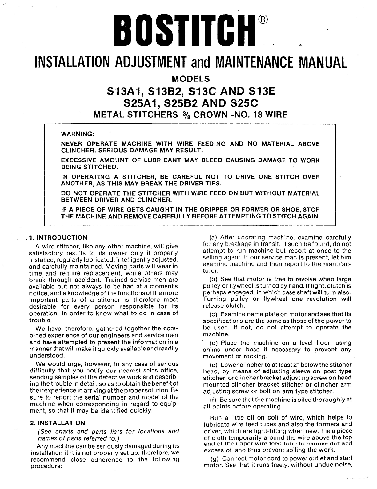
S13A1
STITCHER
NOTE:
SEE
S13C STITCHER
CHART (PAGE
7) FOR
BODY,
BASE,
DRIVE
AND
TRIP
PARTS.
fl
Page 5
Ul
I
Page 6
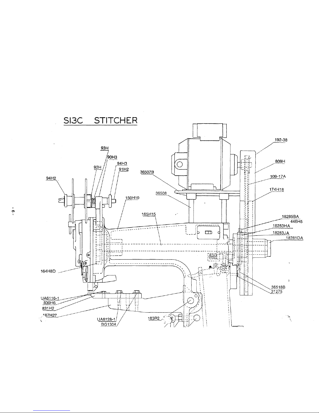
SI3C
STITCHER
192-38
UA6116-1
830H6
831H2
Page 7

/
\
,
'
1 1
1
,
I I —
-—-"
t^-"
—
""^
i
^^^^£
i
i
^f**^
*^-
•v^**
t
i
--'
_-—
-
^
—
UB4124.2
36506
Page 8

S13E
STITCHER
oo
i
192-38
36583
18285BA
446H5
18283HA
365730^
36571BA
36575D
18283JA/1S281DA
36576C
Page 9

36523A
36551BA
CO
\_36544_
36543B
UB4124.2
85173-11OV-AC
85180-220V-AC
85185-230V-DC
36557
36546B
36547B
Page 10

S25C
STITCHER
192-38
93
H
18283JA
18281
DA
830H13
831H11
UA7114.1
UA5812.5
UA8840J3
UB4124.
J
Page 11

(
L
seer;
36658
FOR
PARTS SPECIAL
TO
S25A1 & S25B2
STITCHERS
SEE
LIST
IN
REAR
OF
BOOK
85173-11OV-AC
85180-220V-AC
85185-230V-DC
Page 12

S13B2
STITCHER
NOTE:
SEE
S13C
STITCHER
CHART (PAGE
7) FOR
BODY,
BASE, DRIVE
AND
TRIP
PARTS
UA6824.3
HN3816.2
50H15
821H
-TOP
CLINCHER
MOUNTING
(AS
SHOWN)
821H2-
BOTTOM
CLINCHER
MOUNTING
SB825
_BG1_114
824H
SPACER
Page 13
•\
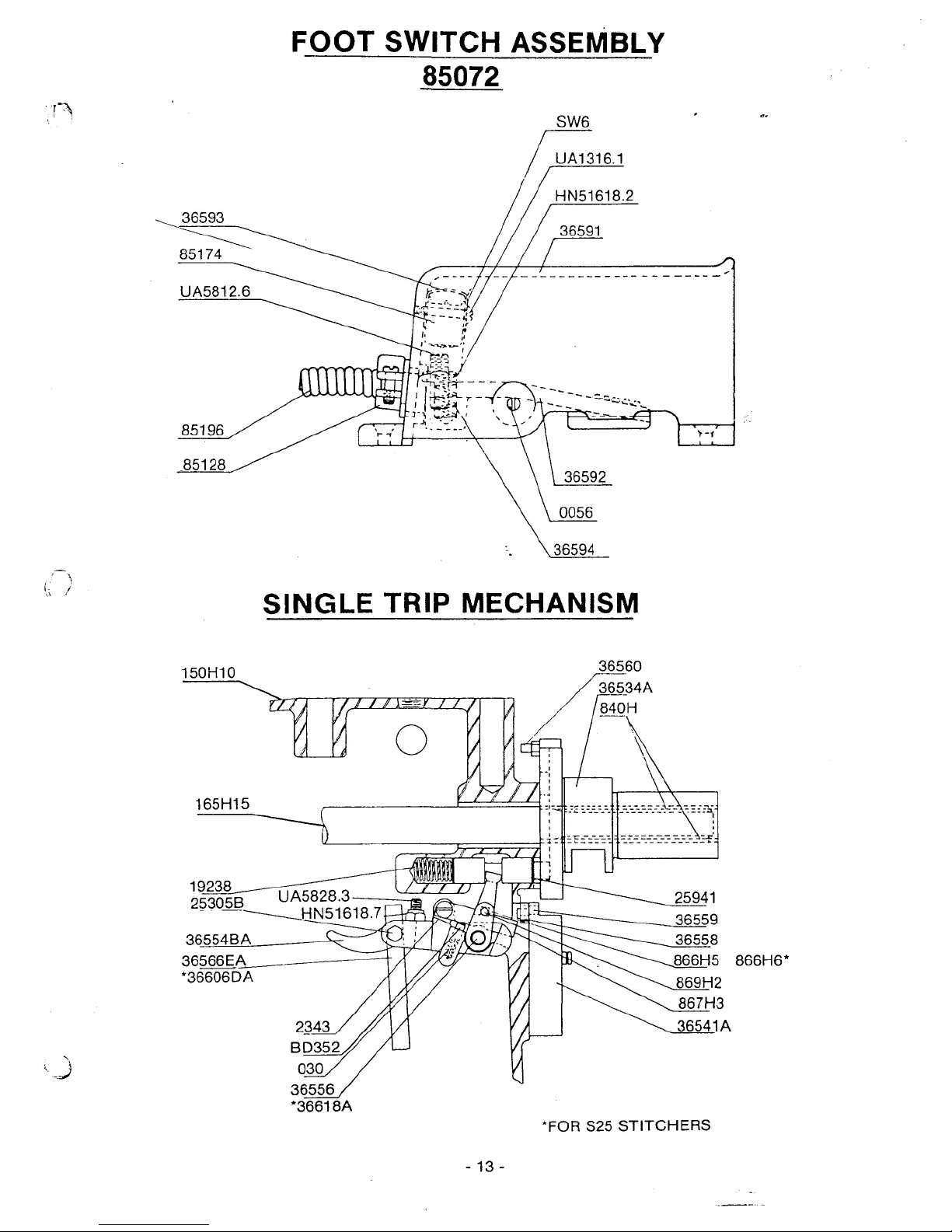
FOOT SWITCH
ASSEMBLY
85072
SINGLE
TRIP MECHANISM
150H10
J—
«.
/
I
1
/
/I
o
si.
/
/
/
/
/
/
36560
36534A
840H
165H15
19238
253Q5B
36554BA
36566
E_A
*36606DA
*FOR
S25
STITCHERS
- 13-
Page 14

INSTRUCTIONS
FOR USE OF
JAM
RELEASING
WRENCH
INSERT PINS
IN
WRENCH BSA37
INTO
TWO
HOLES
IN
DRIVE
PULLEY WASHER 18281DA
AND
TURN
IN THE
DIRECTION
SHOWN
ON
SKETCH
WRENCH
DRIVE
PULLEY
WASHER
18281
DA
-
14-
Page 15

2336
2333
CLUTCH
AND
BRAKE
2340B
UNIT
446H5
18283HA
25942
18284
UB7824.1
0
18283JA
18287
MIN.
2347
MAX.
2347A
CLUTCH
25766
RING
ASSEMBLY
E165
- 15 -
Page 16

CLINCHERS
FOR
S13A1,
S13B2,
AND
S13C STITCHERS
PLAIN
CLINCHERS
RAISED
CLINCHERS
o
OPEN
END
CLINCHING SURFACE
(With 2 Drilled
Holes)
830H6
- 45°
Angle
of
Contact (Standard) S13C, S13B2
830H17 - 37y2°
Angle
of
Contact
(With 2 Tapped
Holes)
830H13
- 45°
Angle
of
Contact (Standard) S25C
GROOVED
CLINCHING
SURFACE
830H11 - 45"
Angle
of
Contact
OPEN
END
CLINCHING SURFACE
(With 1 Tapped Hole)
830H19
- 45°
Angle
of
Contact
GARNISH
MOULDING CLINCHERS
CLINCHING SURFACE
MILLED THRU
LIP
830H
45°
Angle
of
Contact
CLINCHING
SURFACE
MILLED
THRU
OPEN
END
CLINCHING
SURFACE
830H8
- 45°
Angle
of
Contact
830H15
- 45°
Angle
of
Contact
Raised
Vi"
830H21
45°
Angle
of
Contact
Raised
1"
GROOVED
CLINCHING
SURFACE
830H39
- 45°
Angle
of
Contact
Raised
W
PASS-BY
CLINCHING
SURFACE
830H47 - Raised
%"
SINGLE
CLINCHING
SURFACE
MILLED THRU
830H20
- 45°
Angle
of
Contact
Raised
2"
POST
CLINCHERS
OPEN
END
CLINCHING SURFACE
830H24
- 45°
Angle
of
Contact
(Raised
3")
830H37 - 37'/2"
Angle
of
Contact
(Raised
3")
CLINCHER ADAPTERS
832H
- For Use
With
V4",
%"
and
1"
Raised
Clinchers
280G
- 45°
Angle
of
Contact (Standard)
280G2 - 37 W Angle
of
Contact
832H2
- For Use
With
2"
Raised
Clincher
CLINCHER HOLDERS
831H2
-With
Tapped
Clincher
Hole
(Standard) S13C
831H11
-With
Drilled
Clincher
Hole
(Standard) S25C
S31H7
- For Use
With
3"
Raised
Clincher
830H24 (S13C
Only)
831H8
- For Use
With
3"
Raised
Clincher
830H24 (25C
Only)
Movable Clincher Solid Clincher
Solid
Clincher
37
'A"
45°
Sectional
View
Showing Types
of
Clinchers
W'
-16-
Page 17

PARTS
FOR
S13A1, S13B2, S13C, S13E, S25A1,
S25B2
AND
S25C
STITCHERS
90H3
91H2
92H
93H
94H2
94H3
148H
164H8D
174H18
446H5
809H
840H
867H3
869H2
997H
BD352
0056
030
030
1015H
2333
2336
f>340B
*
^2341
2343
2347
2349
2350
9051
18281
DA
18283HA
18283JA
18284
18285BA
18287
19238
25305B
25941
25942
31275
36506
36518B
36519
36534A
36554BA
36558
36559
36560
O
36562
-^36591
36592
Spoolholder Bracket 36593
Spoolholder
Spindle
36594
Spoolhoider
Thrust
Washer—Assem.
36658
Spoolholder Friction Spring
36659
Spoolholder Lock
Nut
36660
Spoolholder Spindle
Jam Nut
Drive
Shaft
Bushing—(Back)
85072
Drive
Cam
85174
Drive
Pulley
— 9"
Clutch 85173
Brake
Band Assem.
(9"
Clutch)
85180
Drive
Pulley Guard
85185
Clutch Sleeve
Key
85202
Latch
Latch
Contact
85847
Spoolholder Lock
.
86039
Latch
Spring Plunger 88293
Foot
Switch Treadle Pivot
BSA37
Latch
Spring
109-17A
Pulley
Washer Screw Lock Spring 192-38
Drive
Bar
Link
Bushing
Clutch Lever 192-40
Clutch Lever
Spring
Plunger
Brake
Band Adjusting Screw
192-44
Brake
Band Adjusting Screw Lock
Latch
Pivot Stud HN1420
Clutch Ring Expanding
Pin
HN1420.4
Pulley
Washer Screw HN51618.2
Pulley
Washer
Screw Lock HN51618.7
Brake
Band Adjusting Screw Lock Spring
HN51624.2
Pulley
Washer — Assem. LW14
Brake
Ring LW716
Clutch Ring — Assem.
9"
Clutch
Clutch Pawl Plunger PW516
Brake
Band — Assem.
(4"
Clutch)
SW6
Clutch Lever Pivot UA1316.1
Stop Plunger
Spring
UA3808.9
Solenoid Connecting Link
Pin
UA4112.1
Stop Plunger UA4814.1
Clutch Pawl
UA5112.1
Brake
Band Link
Clip
UA5114.1
Solenoid Cover Plate UA5116.1
Brake
Band Link UA5804.1
Brake
Band Link
Stud
UA5820.1
Clutch
Sleeve — Assem. UA5824.1
Connecting Link
Arm
UA5828.3
Single
Trip
Lever UA7140.1
Single
Trip
Lever Pivot UA7816.1
Single
Trip
Screw UA8832.8
Solenoid Bracket UB2908.1
Foot Switch Base
UB3108.2
Foot
Switch Treadle
UB4124.2
Micro Switch Shield
Foot
Switch Treadle
Spring
Solenoid Connecting
Link
Spring
Solenoid Spring Bracket
Solenoid Connecting LinkSpring Retaining
Washer
Foot
Switch — Assem.
Micro Switch
Solenoid
— 110
Volt — A.C.
Solenoid
— 220
Volt — A.C.
Solenoid
— 230
Volt — D.C.
Oiler
Drive
Shaft
Bushing (Front)
Circuit
Breaker
Grease
Fitting
Pin
Wrench (For re-setting Head)
V
Belt
Motor
Pulley
(%
Bore)
for 295
Stitches
per
minute with 1725
R.P.M.
Motor
MotorPulley
(%
Bore)
for295
Stitches
per
minute with 1425 R.P.M. Motor
Motor Pulley
(%
Bore)
for 295
Stitches
per
minute with 1425 R.P.M. Motor
Solenoid
Screw
Nut
Solenoid Spring Bracket
Nut
Switch
Contact Screw Lock
Nut
Connecting
Link
Stop
Nut
Solenoid Connecting
Link
Pin Nut
Solenoid Screw Lock Washer
Solenoid Bracket Screw Lock Washer
Pulley Guard Screw Washer
Micro Switch Screw
Lock
Washer
Micro Switch Screw
Solenoid Cover Plate Screw
Solenoid Screw
Solenoid Spring Bracket Screw
Pulley
Guard Screw
Spoolholder Bracket Screw
Spoolholder Bracket Screw
Pulley
WasherScrew Lock Spring Screw
SingleTrip Lever Pivot Block Screw
—(Short)
SingleTrip
Lever
Pivot
Block
Screw—
(Long)
Connecting Link
Stop
Screw
Head
to
Body Screw
Drive
Cam
Screw
Motor Plate Stud Screw
Spoolholder Thrust Washer Cotter
Spoolholder Lock
Nut
Stop
Pin
Solenoid Spring Retaining
Fin
-17-
Page 18

PARTS
FOR
S13A1, S13B2, S13C
AND
S13E STITCHERS
150H10 Body
151H351/2 Base
165H15 Drive Shaft
866H5
Stop Plunger
Lever - Assem.
2335
Clutch
Lever
Spring
36507B
Motor
Plate
36508
Motor
Plate Stud
36541A
Single
Trip
Lever
Pivot Block
36556
Connecting Link
Arm
Pivot
36566EA
Solenoid Connecting Link
UA5802.2
Guard Screw
UA7124.1
Body
to
Base Screw
LW716
Body Screw Lock Washer
UA7124.1
Solenoid Bracket Screw
UA5510.1 Motor Plate
Screw
UA8528.2 Motor Plate Stud
Screw
UA8524.2
Clincher
Arm
Pivot
Lock
Screw
PARTS
FOR
S25A1, S25B2,
AND
S25C STITCHERS
150J13 Body
Q151L7 Base
178H8
Motor
Plate
866H6 Stop Plunger
Lever - Assem.
2335
Clutch
Lever
Spring
36606DA
Solenoid Connecting Link
36607A
Drive
Shaft
36618A Hand
Trip
Assembly
LW58
Body Screw Lock Washer
UA7120.1 Solenoid Bracket Screw
UA8532.1 Post Binding
Screw
UA9132.1
Body
to
Base
Screw
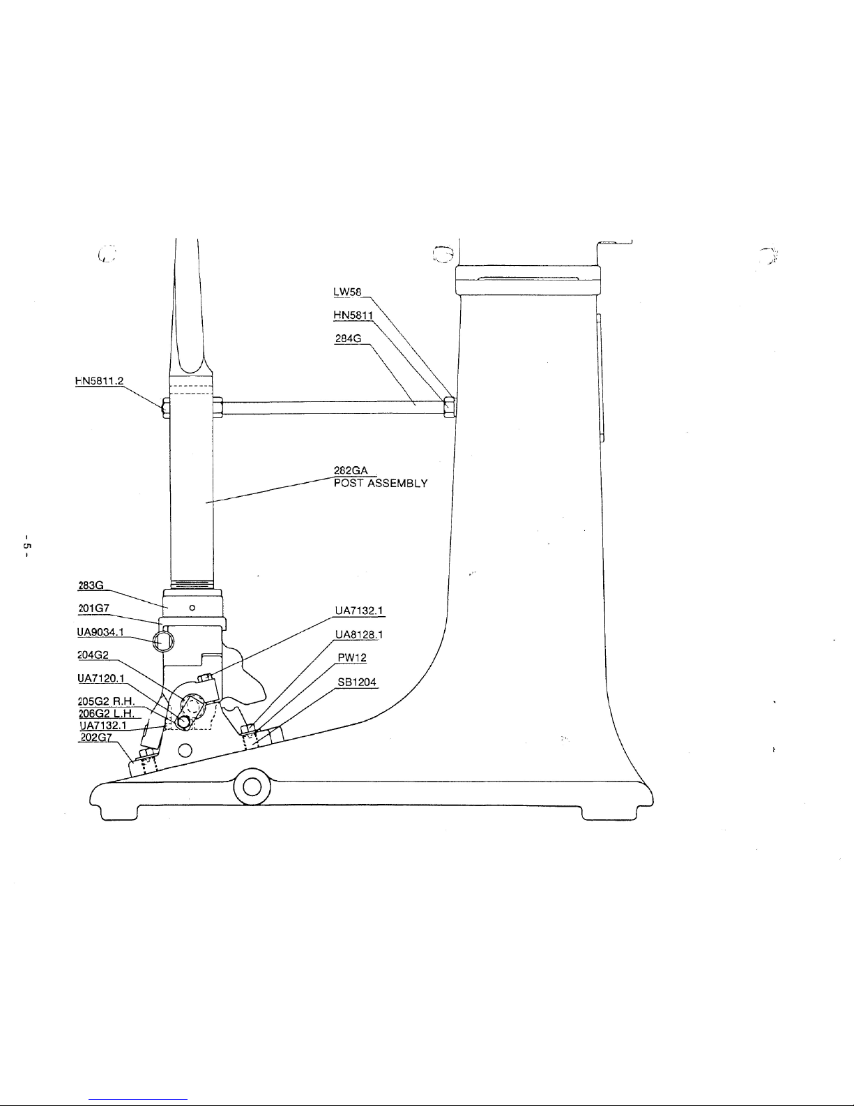
PARTS
FOR
S13A1
AND
S25A1 STITCHERS
r
201G7
Post Pivot Head
202G7 Post Base
204G2
Post Pivot
Pin
205G2
Post Pivot
Pin Cup -
Right Hand
206G2 Post Pivot
Pin Cup -
Left Hand
283G Post
Adjusting
Nut
SB1204 Post Base Leveling
Bushing
HN5811
Post Brace Lock
Nut
HN5811.2
Post Brace Lock
Nut -
(Front)
LW58 Post Brace Lock Washer
PW12
Post Base Screw Washer
UA3408.1 Clincher Screw
UA7120.1
Post
Pivot
Cup
Adjusting Screw
UA7132.1
Post Pivot
Cup
Clamp Screw
UA7132.1
Post
Pivot Head Lock
Screw
UA8128.1 Post Base Screw
UA9832.7
Post Clamping Screw
Note:—
See
page
16 for
Clinchers
PARTS
FOR
S13A1 STTCHER ONLY
183H Clincher
Arm
Locking
Pin
183R2
Clincher
Arm
Pivot
186H2
Arm
Hole
Cover Plate
282GA
Post
Column
Assem.
284G
Post Brace
2338 Clincher
Arm
Locking
Pin
Plug
36666 Guard
UA3305.1
Arm
Hole Cover Plate Screw
UA8810.2
Clincher
Arm
Lock
Pin
Screw
PARTS
FOR
S25A1 STITCHER ONLY
282G3A
Post Column Assembled
284G3 Post Brace
36630A
Single Trip
Pivot
Block
- 18 -
Page 19

PARTS
FOR
S13B2,AND
S25B2
STITCHERS
129H5
Gripper
Spring Pivot
821H
Clincher Bracket - (Standard)
for
Top
Clincher
Mounting
821H2 Clincher Bracket
for
Bottom Clincher
Mounting
824H
Clincher Bracket Spacer
BG1114 Clincher Bracket Screw Washer
SB825 Clincher Bracket Screw - (Lower)
14212
Base Plate
228-13 Clincher Bracket Screw Washer
HN3816.2 Clincher Bracket Adjusting Screw
Lock
Nut
HN71614
Clincher Bracket Screw
Nut
PW38 Clincher Screw Washer
UA6116.1
ClincherScrew-ForTopClincherMounting
UA6128.1
Clincher Bracket Screw
UA6824.3 Clincher Bracket Adjusting Screw
UA8116.1
Base Plate Screw
UA8120.1
Clincher
Screw-For
Bottom Clincher
Mounting
Note:—
See
page
16 for
Clinchers
PARTS
FOR
S13B2
STITCHER
ONLY
183H Clincher
Arm
Locking
Pin
183R2
Clincher
Arm
Pivot
186H2
Arm
Hole
Cover
Plate
2338 Clincher
Arm
Locking
Pin
Plug
36666 Guard
UA3305.1
Arm
Hole Cover Plate Screw
UA8810.2
Clincher
Arm
Lock
Pin
Screw
PARTS
FOR
S25B2
STITCHER
ONLY
36630A
Single
Trip
Lever Pivot Block
PARTS
FOR
S13C
STITCHER
ONLY
183H Clincher
Arm
Locking
Pin
SB917
183R2
Clincher
Arm
Pivot
SW916
187H27
Clincher
Arm
189J2 Clincher
Arm
Adjusting Screw
UA6116.1
BG1304 Clincher
Holder
Washer
UA8116.1
2338 Clincher
Arm
Locking
Pin
Plug UA8128.1
14212
Base Plate
UA8516.1
36666
Guard
UA8810.2
HN1213.2
Clincher
Arm
Side Adjusting Screw
Lock
Nut
Note:—
HN5818.2
Clincher
Arm
Adjusting Screw
Lock
Nut
Clincher
ArmSide
Adjusting Screw
Clincher
Arm
Side Adjusting Screw Lock
Washer
Clincher
Screw
Base
Plate
Screw
Clincher Holder Screw
Clincher
Arm to
Pivot Screw
Clincher
Arm
Lock
Pin
Screw
See
page
16forClinchers,ClincherHolders,
and
Clincher Adaptors
PARTS
FOR
S25C
STITCHER
ONLY
WJ16
Arm
19276
Clincher
Holder
Washer
14212
Base Cover
36610
Arm
Binding
Screw Washer (Rear)
36630A
Single
Trip
Pivot Block
36633
Arm
Binding
Screw Washer (Front)
36648
Wear Block
'UA5812.5
Arm
Adjusting
Set
Screw
UA7H4.1
CKncfier
Screw
UA8116.1
Base Cover Screw
UA8120.1 Clincher Holder Screw
UA8840.3
Arm
Adjusting Screw
UA9076
Arm
Elevating Screw
UA9160
Arm
Clamp Screw
HN5811
Arm
Locating Screw Lock
Nut
- 19 -
Page 20

PARTS
FOR
S13E STITCHER ONLY
BG300
Clincher
Arm
Adjusting EccentricSet 850200
Screw
Plug 85327
14212
Base Plate
85328
B512B
Clincher
Operating
Lever
Slide
Pin
85329
36523A
Clincher
Arm
HN51618
36527
Clincher
Arm
Pivot
Pin
HN51618
36528A
Clincher
Arm
Adjusting Eccentric HN1213.2
36530
Clincher
Arm
Adjusting Bolt
HN1213.2
36531
Clincher
Arm
Adjusting
Bolt
Pin
36537A
Clincher
Cam
Slide HN1420.5
36538
Clincher
Cam
Slide
Roll HN5811
36540
Clincher
Cam
Slide Roll Retainer
PW516
36542
Clincher
Cam
Slide Plunger
PW516
36543B
Clincher
Cam
Slide Lever
SW916
36544
Clincher
Operating
Lever Pivot
36544
Clincher
Cam
Slide Lever Pivot
UA3406.2
36546B
Push
Rod
36547B
Push
Rod
Guide
UA3406.2
36550C
Push
Rod
Guide Spring Plate
36551BA
Clincher Operating Slide
UA3406.2
36555
Clincher Operating Slide Spring
36557
Clincher Operating Slide Spring Hook UA4816.1
36571BA
Clincher
Holder
UA4828.1
36573D
Clincher
UA4812.1
36574
Clincher Screw
UA5110.1
36575D
Clincher Slide UA5112.1
36576C
Clincher Operating Lever UA5128.1
36577B
Clincher Slide
Tip
UA5412.1
36581
Air
Valve
Bracket UA5828.2
36583
Air
Valve
Lever UA8116.1
36585
Air
Valve
Lever Pivot UA8520.1
36587
Air
Tube
UA8532.2
36665
Guard UA8832.3
85325
Ai r Tu
be
Adapto
r
Air
Valve
Air
Petcock
Air
Petcock
Nipple
Air
Line Coupler
Air
Valve
Lever Pivot Screw
Nut
Air
Valve
Guard Screw
Nut
Clincher
Arm
Side Adjusting Screw Lock
Nut
ClincherOperating
Slide
Adjusting Screw
Lock
Nut
Air
Valve
Screw
Nut
Clincher
Arm
Adjusting
Bolt
Nut
Air
Valve
Lever Pivot Washer
Air
Valve
Screw
Washer
Clincher
Arm
Side Adjusting Screw Lock
Washer
Clincher
Operating Lever Pivot
Retaining
Screw
ClincherCam
Slide
LeverPivot
Retaining
Screw
Clincher
Arm
Adjusting Bolt
Pin
Retaining
Screw
Clincher Holder Screw
Push
Rod
Guide Screw
Air
Valve
Screw
Air
Valve
Guard Screw
Air
Valve
Bracket Screw
Air
Valve
Lever Pivot Screw
Air
Valve
Bracket Screw
Clincher
Cam
Slide
Roll
Retainer Screw
Base
Plate Screw
Clincher
Arm
Adjusting Eccentric
Set
Screw
ClincherOperating
Slide
Adjusting Screw
Clincher
Arm
Adjusting Screw
/—i
n
BOSTITCH Division
of
Textron Inc.,
East
Greenwich,
R. I.
02818, U.S.A.
BSA 360 D
5-76
LITHO
IN
U.S.A.
 Loading...