

Page 1
t
A
S:
f
i
INSTRUCTIONS
AND
PARTS
LISJ
OF THE
N°
14
&
N°
14B
../•
BOSTITCH*
WIRE
STITCHERS
..
•
it;
i-4'
;v
•••,'••..•
;•..••
'jSf
^^P^MlMii
V
BELT
DRIVE
USES
Ne
15001D
HEAp
When
in
need
of
Parts
or
Service
Contact Your Bostitch
Distributor.
You
will
find
"BOSTITCH"
listed
in
phone
books
of
most
large
cities.
Fasten
It
Better
ad
Fasfer
'
5
STAPLERS
AND
STAPLES
>^
^-X/."
•:-v:\::
>M
-.•,:ra^P-,-.-:;
••• • :••
•'•'r-ftS'r^ift'^"""
Page 2

INSTALLATION,
OPERATION
AND
MAINTENANCE
of
No.
14
AND No. 14B
BOSTITCH
WIRE STITCHER
WITH
No.
15001D
HEAD
;;
CAPACITY:
9/16"
SIZE
OF
WIRE:
.017
thru
.023
Ribbon
No. 1 and 2
Hybar
No.
18x20,
19x21'/a,
20x24,
20x25
and
21x25
Flat
No.
18,
20, 22, 23, 24 and 25
thru
27
Round
CROWN
OR
STAPLE
WIDTH:
%", W (Standard),
%"
and
%"
SPEED:
Up to 300
stitches
per
minute
Note:
This
book
does
not
include
head
instructions.
It
should
be
used
in
conjunction
with
"Instructions
and
Parts
List
for No.
15001D,
18001D,
18001D27
and
19001D
Bostitch
Wire
Stitcher
Heads."
1.
INTRODUCTION
To
obtain
satisfactory
results from a wire stitcher,
as
with
any
other machine,
it is
necessary
that
it
be
properly installed
and
adjusted, regularly
lu-
bricated,
and
carefully maintained.
In
case
of any
serious
trouble, however,
you
should
notify
the
nearest
sales
office,
sending samples
of
the
defective
work
and
describing
the
trouble
in
detail,
so as to
obtain
the
benefit
of
their experience
in
arriving
at the
proper solution.
Be
sure
to
report
the
serial number
and
model
of the
machine when
corresponding
in
regard
to it, so
that
it may be
quickly identified.
2.
INSTALLATION
To
prevent
damaging
the
machine during
its
installation,
we
recommend that
the
following pro-
cedure
be
closely
followed:
a:
After
uncrating
machine, examine carefully
for
any
breakage
in
transit.
If
such
is
found,
do
not
attempt
to run
machine
but
report
at
once
to the
selling
agent.
If
service
man is
present,
let
him
examine machine
carefully
and
then
report
to
manufacturer.
b:
Examine name plate
on
motor
ana see
that
its
specifications
are the
same
as
those
of the
power
to
be
used.
If
not,
do not
attempt
to
use.
c:
Since'each machine
is
shipped with some
parts
disassembled,
it is
necessary
that
these
parts
be
reassembled onto
the
machine.
Attach
spool stud
and
disc, wire guide spring,
ad-
justing
screw
crank
arm, motor bracket,
motor,
V
belts, belt shield
and
belt guard.
The
mounting
of
motor onto
the
base
is a
simple
matter
which needs
no
explanation. When
assem-
bling-
belts, make sure
that
they-
are
only
tight
enough
to run
machine
without
slippage. Belt ten-
sion
may be
adjusted
by
moving motor bracket
up
or
clown.
d : Place machine
on
level
floor,
using shims under
base
to
prevent
any
movement
or
rocking.
e:
Lubricate machine thoroughly
as
described
in
head instructions
and as
follows:
Apply generous
supply
of oil
(S.A.E.
10) to
pulley
washer
as
this
lubricates
clutch.
Oil
drive
shaft through
oil
cups
(2) at top of
frame
and oil
universal
joints
in
drive
shaft
through large holes
(2) in
left
side
of
frame.
f:
Trip
the
clutch
by
means
of the
movable foot
pedal
at
front
of
machine
and
turn machine over
by
hand
a few
times
to see
that
everything
is
clear.
Then
take
foot
off
clutch
trip
pedal
and
rotate
clutch pulley rapidly,
so
that
clutch
will
be
entirely
disengaged.
Do not
turn
electric
switch
on
until
pulley
rotates
freely.
g:
Connect motor cord
to
power outlet
and
start
motor.
See
that large
pulley
or flywheel
turns
in
direction
of
arrow cast
on
pulley,
or
clockwise
as
viewed
from
the
front
of the
machine. Should
it
rotate counter-clockwise, motor
wiring
should
be
re-connected
by
electrician
in
order
to
reverse
direction
of
rotation.
h:
If
rotation
is
correct, push down
on
foot pedal
and
start
machine operating. Remove foot from
pedal
and
machine
will
stop. A very little practice
will
enable operator
to
know exactly
how to
stop
and
start
machine
exactly
when
desired.
The
following units
are not
standard equipment
on
No. 14
Stitcher
and are
furnished
special
to
order only.
Instructions
follow
for
installing same.
Continuous Feed
Device
or
Tucker
Unit:—This
is
attached
by
placing
groove
in
same over swivel
holder
clamp
on
bonnet
and
holding same with
one
screw provided.
Page 3
Table:—-Remove
clincher ba'r. Attach yoke
to
table,
being sure
that
thin
shim
is
attached with yoke
to
table. Place
table
on
arm, enter
lugs
on
table
in
holes
in
frame,
and
push
in
until dowel
in arm
enters
hole
in
shim.
Work
guide
can now be at-
ached.
Clamp from either end.
Parallel
Head
Attachment:—This
is
attached
in
the
following
manner : Remove head from machine
as
explained
in
head
instructions. Place
one
exten-
sion
block
on
each
of the
slides,
(adjusting driver
and
bender) over
tongues
with
screws
provided,
long
end of
block
to
left
with
oil
hole
on
top. These
blocks
should
be
tight.
Place long bonnet screws
in
frame.
These
are
special screws. Attach
the
exten-
sion
head
block
on
these screws
and
turn crank
into
vertical
position.
Attach
links
to two
lower exten-
sion
blocks.
Attach
head,
facing
the
right,
and
raise
bender
bar to top of
stroke.
Insert
crank
pin
into
hole
in
lower link. Insert
ball
end of
adjusting
link
into
upper block. Move
adjustment
screw
up
or
down
until
hole matches
ball
end. Enter bonnet
screws
in
head
and
tighten. Attach bonnet guard
— A special offset
arm is
necessary with this
attachment.
3.
OPERATION
a:
Place a spool
of
wire
of the
proper size
on
the
spool holder
located
near
the
stitching mech-
anism
or
head.
When
loading
with
wire
wound
on
paper
cores:
Remove
detachable
flange
from
spool
and
insert
coil
of
wire, replacing
flange
and
turning coil till
binding
wires
are
aligned with
slots
in flanges.
Tighten
nut
till coil
is
snugly held.
Cut
binding
wires,
except
the one
holding
the end of the
coil.
(They
may be
pulled
out
through
the
slots.) Then
grasp,
end of
coil
and cut and
remove
the
binding
wire which holds
it.
Thread
the
machine
as de-
scribed
in
head instructions.
b:
Referring
to
head
operating adjustments
in-
structions, follow procedure
for
remainder
of
operations required,
such
as
wire
straightening
and
adjustment
for
length
of
wire.
Gauge
for
thickness
by
placing work under gauge
at
left
of
head
and
adjust crank
at
right
of
head
until
work
is
tightly
pinched under gauge. After
turning pulley
by
hand
once
so as to be
sure
that
machine
is
properly
set for
tnickness
to be
stitched,
power
can be
applied.
c:
Machine
is now
ready
to do
stitching
and
with
directions
as
outlined,
above satisfactory results
should
be
obtained. Make several rows
of
stitches
in
stock
to be
used,
examining crown
and
legs
for
proper
appearance.
If not
satisfactory, adjust
machine
in
accordance
with
directions given
be-
low.
See
section 4 "Appearance
of
Stitches"
and
"Trouble
Shooting
Chart"
in
head
instructions.
d:
CAUTION: — Never
operate
machine
u-ith
U'ire
feeding
and no
stock
above
clinchers.
Serious
damage
may
result
if
this
practice
is
followed.
4.
APPEARANCE
OF
STITCHES
If
stitching
is
defective,
compare stitch
produced
with
illustrations
in
head
instruction
manual.
To
eliminate
defect, follow
instructions
given
with
illustration
that
agrees
with defect.
If
it is
necessary
to
correspond
about
any
defective
stitches
or
other
difficulties
with
the
machine,
be
sure
to
refer
by
letter
to the
illustration
in
head
•instructions
book, which shows
the
type
of
stitch
defect
and,
if
possible, send a sample
of the
work
actually
being done
on the
machine.
5.
*THE
ESSENTIAL
POINTS
OF
STITCHING
In
order
to
continue
to
obtain
satisfactory
stitches
it
is
necessary
that
the
-following
essentials
be
observed:
a: The
legs
of the
staple must
be of the
same
length.
b:
Wire must enter cutters
as
nearly straight
as
possible.
c:
The
cutters
or
knives must
be
sharp
and
prop-
erly
set so
that there
arc no
burrs
on end of
wire
and
wire
is cut
with a square
end
(not
beveled).
d:
Clincher
must
be in
good condition with
no
pitted
or
badly worn grooves.
For
best
results
in
stitching
with solid
clinchers
the
compression gen-
erally
should
be
such that
the
ends
of
bender
bar
very
slightly indent
the top of the
work.
e:
The
machine must
be
kept clean
and
properly
oiled.
f:
The
wire
must
be of the
correct size
for
stock
to be
stitched
and
must
be
used only
in
the
proper
bender
bar. Wire
fitting the
bender
bar
grooves
too
loosely
will
cause
buckling,
and too
large a wire
will
also cause buckling
in
addition
to
excess
wear
on
the
bender bars.
Be
guided
by the
operating
instructions
for the
proper
size
wire.
g:
The
wire spool must
be
free
to
turn
and the
wire
must
not be
allowed
to
become crossed. Short
staples
and
even entire
failure
to
produce
staples
may
result from crossed
or
tangled wires.
h:
The
wire feed grip must
not
have edge
badly
chipped
or
worn. Short
leg
staples
on one
side
can
be
caused
by
these
conditions.
*The
necessary
adjustments,
replacements,
etc.,
required
to
meet
conditions
as
listed
above
are
described
in
detail
in the
head
and
stitcher
instruc-
tions.
6.
MAINTENANCE
a:
Machine should
be
lubricated regularly
as de-
scribed
under heading
of
"Installation"
in
this
pamphlet
and
under
heading
of
"Maintenance"
in
head
instructions.
b: The
friction
clutch
is
adjusted
by
means
of
screw 2340B
in
brake band 2339A. Screw
in if
clutch
slips. Screw
out if
clutch
knocks. A quarter
Page 4
turn
will
make
considerable-difference
in
action
of
the
clutch.
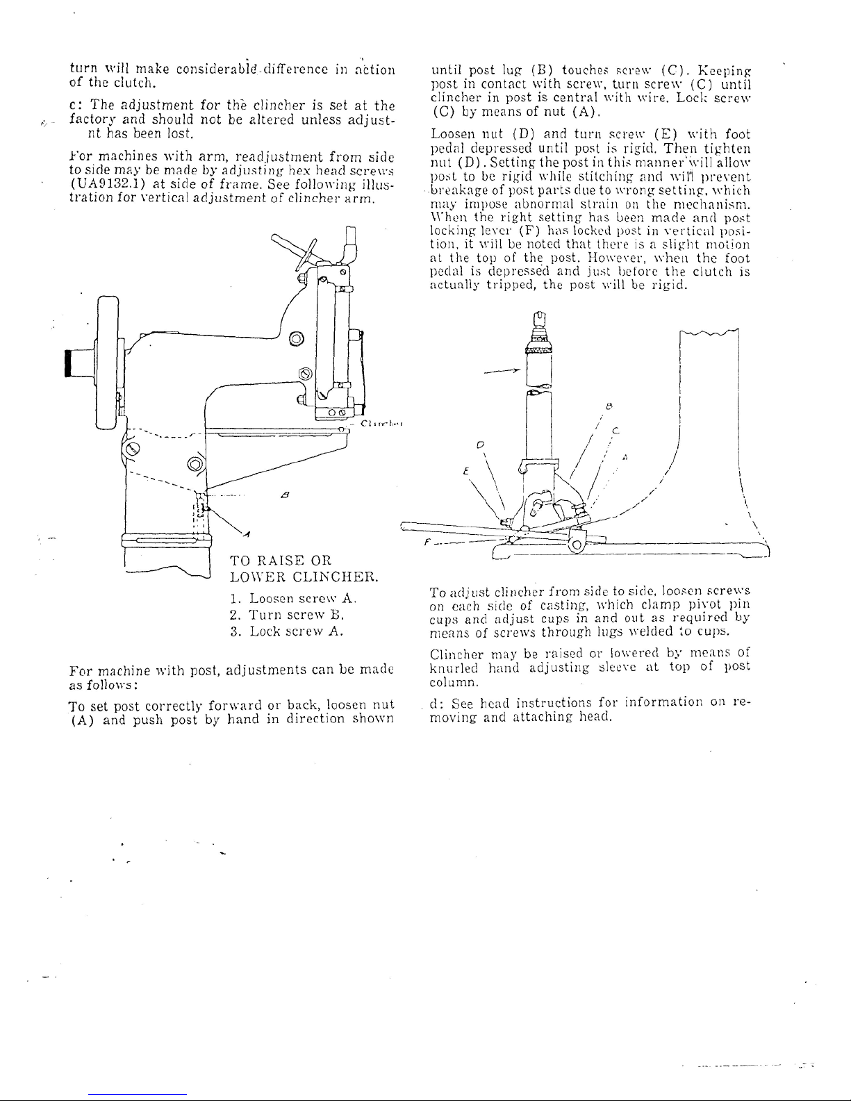
c: The
adjustment
for the
clincher
is set at the
factory
and
should
not be
altered
unless
adjust-
nt has
been
lost.
For
machines
with
arm,
readjustment from
side
to
side
may be
made
by
adjusting
hex
head
screws
(UA9132.1)
at
side
of
frame.
See
following
illus-
tration
for
vertical adjustment
of
clincher arm.
TO
RAISE
OR
LOWER CLINCHER.
1.
Loosen screw
A.
2.
Turn screw
B.
3.
Lock
screw
A.
For
machine with post, adjustments
can be
made
as
follows:
To set
post correctly forward
or
back, loosen
nut
(A) and
push
post
by
hand
in
direction shown
until
post
lug
(B)
touches
screw (C).
Keeping
post
in
contact
with screw, turn screw
(C)
until
clincher
in
post
is
central with wire. Lock screw
(C) by
means
of nut
(A).
Loosen
nut (D) and
turn screw
(E)
with foot
pedal
depressed
until
post
is
rigid. Then tighten
nut
(D).
Setting
the
post
in
this
manner'will
allow
post
to be
rigid
while
stitching
and
wil'l
prevent
breakage
of
post parts
due to
wrong
setting,
which
may
impose
abnormal
strain
on the
mechanism.
When
the
right
setting
has
been
made
and
post
locking
lever
(F) has
locked
post
in
vertical
posi-
tion,
it
will
be
noted
that
there
is a slight
motion
at the top of the
post.
However,
when
the
foot
pedal
is
depressed
and
just
before
the
clutch
is
actually
tripped,
the
post
will
be
rigid.
To
adjust clincher from side
to
side, loosen
screws
on
each side
of
casting, which clamp pivot
pin
cups
and
adjust cups
in and out as
required
by
means
of
screws through lugs welded
to
cups.
Clincher
may be
raised
or
lowered
by
means
of
knurled
hand
adjusting
sleeve
at top of
post
column.
d:
See
head instructions
for
information
on re-
moving
and
attaching head.
Page 5

Page 6

NO.I4BOX'
STITCHER
N0.14B
BOTTOMING
STITCHER
Page 7

INSTRUCTIONS
FOR
OPERATING BOSTON WIRE STITCHER
HEADS
No.
15 & No. 15D
Sizes
of
Wire - Ribbon
or box
stay wire
No. 8 to No, 25 -
Rybar
wire
- No. 18 & 19
round wire
- No. 20 to 25
round
and No. 20
2:
24
& 21 x 25
flat.
Width
of
staple
1/2
regular
- 3/8 - 5/8 - 3/4
special.
Capacity
in
thickness
1/2
inch.
* No. 15D
Head.
TO
THREAD
run
v/ire
from under
side
of
spool
to
left
around spring
15151A
and
under studs
and
rolls
on
same.
Remove swivel
16066A
by
lifting lower
end of
spring
15084A
*19084A
and
swinging
to
left.
Curve wire
and
enter between
straightener
rolls
19121
and
eccentric
19128A.
Pull
wire down
until
crooked wire
has
passed through
rolls.
Cut
wire
off
with hard wire cutter just above
cutter
holder
15105B.
Enter wire
in
grip 15031
and in
tension rolls 19121 which
are
opened
by
pressing down
rod
19145A
*19147A.
Enter wire
in
slot
in
wire cut-
ter
15101
and
push down
until
wire shows through hole
in
swivel
holder
15072.
TO
STRAIGHTEN
WIRE adjust eccentric
19128A
until wire runs
straight. Start machine
and
watch wire feed past opening
in
swivel
holder. Wire should come directly
in
center
of
opening.
If
wire
curls
to
left, straightener
is not set
tight enough.
If
wire curls
to
right, straightener
is set too
tight.
When
wire runs
straight,
re-
place
swivel
and
attach spring
to
same.
OIL.
Oil
connecting
links
on
back
of
head.
Oil
swivel operating
lever
15078
*19078A.
Oil
slots
at top of
head
at
sides
of
bracket
15154.
Oil
driver
bar at top of
bender
bar
15023A.
Put
drop
of oil
in
angular
slot
in
cutter slide
15115A
*15113A
where
it can be
seen
through large
opening
in
face plate
15091A
*15135A.
Put
drop
of
-oil
on
swivel where
it
slides
in
swivel holder
15072.
TO
ADJUST
LENGTH
OF
WIRE.
To
change length
of
both
legs
of
staple, loosen screw
15088
and
push face plate
15091A
*15135A
up to
lengthen
or
down
to
shorten legs
of
staple. Tighten screw
15088
after
adjusting.
To
increase left
leg of
staple,
loosen screws 15155
and
56
near
the top of
head
and
turn
adjusting screw 15156
to
right.
To
shorten left leg, turn
to
left.
Press
down firmly
on
bracket
15154.
Tighten screws
56 and
15155.
Most adjustments
for
longer wire
can be
made
by
setting machine
for
thicker work.
WIRE
CUTTERS.
To
remove cutter
15104,
first
set
machine
at
mini-
mum
adjustment, then pull
out
slightly
on
spring 15108
and
push
the
little
pin in
cutter slide
15115A
*15113A
to top of
opening
in
face
plate. Cutter will then slide
out
easily. This
cutter
is
double
ended.
To
replace engage tongue
on
cutter
in
slot
in
slide
and
push
slide
down
to
lower
end of
stroke.
When
replacing
cutter,
trip machine
and.
turn
pulley
by
hand
to
bring
the
driver below
cutter.
To
remove
stationary cutter
15101,
loosen
screw 15102
at
left
of
cutter
holder.
Page 8

t.
COMPONENT PARTS
OF
THE
5
Q
I5D
BOSTON
WIRE
STITCHER
EADS
TRADE MARK
BOSTITCH
REG.
TJ.
S.
PAT. OFF.
BOSTON WIRE STITCHER
COMPANY
EAST
GREENWICH,
R. I.
Page 9

15283A
FOR
SHAFT
I5257A
I9283A
FOR
SHAFT
I930IA
15001
^5002
--15097B
15018A
I5283A
FOR
SHAFT I5257A
19283A
FOR
SHAFT
I930IA
-15025
„—-
15053A
15062-
BOSTITCH
LINKS
IN
PARALLEL
POSITION.
15067
BOSTON
WIRE
STITCHER
CO.
COMPONENT PARTS
OF
15
HEAD
LINKS
IN
RIGHT
ANCLE POSITION.
Page 10

I5283A--
FOR
SHAFT
I5257A
QJ|_
I9283A-.
FOR
SHAFT
I930IA
1504.5
1504-8
I5046A
15088
15155
I5094B
15093
15092
15076
I5066A
15072
320
BOSTITCH
1506219088-
9044
15077
L1KJKS
1M
PARALLEL
POSITION!
15012
15101
9057
15067
BOSTON
WIRE
STITCHER
CO.
COMPONENT
PARTS
OF
150018
15002
I5097B
15284
I9283A
FOR
SHAFT
1930
I5283A
FOR
SHAFT
1525'
15025
15027
15024
15026
15057
15056
I5053A
LINKS
IN
RIGHT ANGLE POSITION
5
D-HEAD
Page 11

PARTS
FOR NO. 15
HEAD ONLY
SEE
NO. 15
HEAD
CHART
15001
BOnnet
45.00
15018A
Driving
Slide
9.25
15019 Driving Slide Swivel Oper.
Pin .15
15078
Swivel Operating Lever 2.75
15079
Swivel Operating Lever Stud
.60
15080
Swivel Operating Lever Stop
.55
15081 Swivel Operating Lever Stop Screw
.15
15084A
Swivel Operating Spring 2.50
15091A
Face Plate - Ribbon
and
Hybar Wire 19.55
15115A
Wire Cutter Operating Slide 3.35
19091A
Face Plate - Round Wire 19.55
19145A
Tension Roll Spring
Rod .75
PARTS
FOR
NO.
15D
HEAD
ONLY
SEE NO. 15D
CHART
15001B
Bonnet
15113A
Wire Cutter Operating Slide
15135A
Face
Plate - Ribbon
and
Hybar Wire
19017A
Driving Slide
19020
Driving Slide Swivel
Oper.
Pin
19078A
Swivel Operating Lever
19079
Swivel Operating Lever Stud
19081 Swivel Operating Lever
Hub
19084A
Swivel Operating Spring
19135A
Face Plate - Round
Wire
19147A
Tension
Roll
Spring
Rod
19148 Tension
Roll
Spring
Rod
Guide
45.00
Page 12

PARTS
FOR
BOSTON WIRE
STITCHER
HEADS
NO. 15 AND NO. 15D
06
Adjusting
Screw
Binder
530
Finger Guard
5037
Driver
Retaining
Spring
Rivet
5062
Tension Roll Spring
Eod
Retainer
5160 Driver Release
Pin
7155 Spool Stud
7180
Tension Roll Spring
7224
Wire
Cutter
Slide Friction Spring
7232 Swivel
Hook
7235
Swivel
Hook
Pivot
Pin
7234
Swivel
Kook
Spring
9010 Driver Retaining
Spring
9044
Swivel Holder
Clanp
Screw
9057
Swivel Oper. Lever Stud
Screw
15002
Bonnet Screw
15011 Driver - round wire
15012 Driver - ribbon
wire
15012H
Driver - Hybar
wire
15015A
Driver
Bar
15022A
Bender
Bar -
round wire
15023A
Bender
Bar -
ribbon
wire
15023HA
Bender
Bar -
Kybar
wire
15024
Bender Slide
15025
Bender Slide
Spring
15026
Bender Slide Spring
Plunger
15027
Bender Slide Connection
Pin
15031 Grip - Ribbon Wire
15032A
Grip Holder
15033
Grip Holder Stud
.5034A
Grip
Retaining
Spring
15038
Grip Spring
15039
Grip Spring
Pin
15041 Grip Block - Ribbon
Wire
15042
Grip Block - Round Wire
15043
Grip Block Screw
15045
Grip Release Slide
15046A
Grip Release
Lever
1504S
Grip Release Lever Pivot
15055A
Supporter
15054
Supporter
Pivot
Pin
15055
Supporter Guide
Pin
15056
Supporter Spring
15057
Supporter Spring
Plunger
15061 Supporter Guide
Plate
15052
Supporter Guide Plate Screw
15056A Swivel - Ribbon Wire
15067
Swivel
Wire
Retainer
15070A
Swivel - Hybar
Wire
15072
Swivel Holder
15073A
Swivel Holder Clamp
15076
Swivel
Holder
Guard
15077 Swivel Holder Guard Screw
.05
15083
Face Plate
Adj.
Screw
.35
15089
Face Plate
Adj.
Screw
Nut
.05
15092
Face Plate
Clip
.25
15093
Face Plate
Clio
Screw
.10
15094B
Face Plate Clip
Spring
.35
15097B
Face Plate
Adj".
Slide
.10
15098
Face Plate
Adj.
Slide
Pin
.05
15100 Stationary Wire
Cutter - Hound
Y7ire
.20
15101 Stationary
Wire
Cutter - P.ibbon
Wire
.05
15102 Stationary Wire Cutter Screw
.05
15104 Sliding Wire Cutter
.05
151053
Wire Cutter
Holder
.05
15107 Wire
Cutter
Lock
Pin
.05
15108 Wire
Cutter
Lock
Pin
Spring
.40
15109 Wire
Cutter
Lock
Pin
Spring Screw
2.00
151163
Wire Cutter Slide Friction
2.00 15123 Wire
Straightener
Roll Clip
5.00 15124 Wire Straightener
Roll
Clip
Rivet
2.25 15125
Wire
Straightener
Roll
Clip
Spacer
10.00 15130 Wire Straightener
Eccentric
Block
-
10.00 Ribbon Wire
12.00 15142 Tension Roll Block - Ribbon Wire
4.20
15150A
Wire Guide Spring - Round
V.:ire
.30
15151A
Wire
Guide
Spring - Ribbon Wire
.60
15154 Wire Guide Spring Bracket
.40
15155 Wire Guide
Spring
Bracket Screw
.35
15156 Wire
Guide
Spring Bracket
Adj.
Screw
2.40 15160 Spool
Stud
Friction
Disc
.30
15161 Spool Stud Bracket
.15
15162
Spool
Stud
Bracket
Screw
•
25
15187
Parallel
Slide
Extension
.30
15188
Parallel Slide
Extension
Screw
.90
15283A
Bender Link
.90
15284
Driver
Link
.05
15286
Bender Link Connection
Pin
1.25
15287
Driver Link
Connection
Pin
1.65 19011 Driver
- 20 x 24
Wire
•20 19022A
Bender
Bar
- 20 x 24
Wire
5.25
19065A
S'.vivel - Round Wire
.15
19088
Finger
Guard
Screw
•
15
19121 Wire Straightener Roll
.15
19122 Wire Straightener Roll Stud
.20
19123A
Wire
Straightener
Eccentric
1.05 19130 Wire Straightener Eccentric
Block
-
.05
Round Wire
9.00 19133 Wire Straightener Eccentric Clip
.30
Rivet
12.00 19134 Wire Straightener Eccentric Clip
7.50 Spacer
1.05 19142 Tension Roll Block
2.25
19283A
Bender
Link
.15
1
.25
.25
.80
.20
.05
.80
.25
.00
.75
.20
.70
.50
.25
.10
.30
.15
.10
.10
.15
00
50
50
50
50
45
10
75
25
30
00
25
50
50
20
20
00
00
00
10
2o
10
75
3.00
.15
.00
.00
 Loading...