

Page 1

1
F
F
X
X
S
S
S
SII
P
P
G
Gaattee
w
waayy
A
Add
m
miinniissttrraattoorr
U
Usseerr
M
Maannuuaall
((22F
F
X
X
S
S,, 22
A
A
F
F
X
X
S
S,, 44
A
A
F
F
X
X
S
S))
AApppplliiccaattiioonn RRoomm VVeerrssiioonn:: 111133
VVeerrssiioonn 22..77
DDeecc..,, 2200006
6
Page 2

FXS SIP Gateway User Manual
Note I
RELEASE NOTE:
Version Date Author Modified Contents
2.6 Nov, 2005
Revision for FXS SIP Gateway for Rom Application
version 109.
Page 3

FXS SIP Gateway User Manual
Table of Connect II
Table of Contents
TABLE OF CONTENTS.................................................................................................................. II
LIST OF FIGURES ...................................................................................................................... VI
LIST OF TABLE........................................................................................................................... IX
PREFACE..................................................................................................................................... X
FXS GATEWAY OVERVIEW .....................................................................................................1
CHAPTER 1 VOIP GATEWAY OVERVIEW.....................................................................................2
1.1 FXS Gateway Overview ................................................................................................2
1.2 Features of The FXS Gateway.....................................................................................2
1.3 Default Settings ..............................................................................................................3
1.3.1 IP Parameters..........................................................................................................3
1.3.2 Telnet and Web Login Password..........................................................................3
1.4 Front Panels....................................................................................................................3
1.5 Back Panel Ports............................................................................................................4
1.6 Hardware Specifications ...............................................................................................4
1.6.1 2FXS LEDs ..............................................................................................................4
1.6.2 2AFXS LEDs............................................................................................................5
1.6.3 4AFXS LEDs............................................................................................................6
1.6.4 Back Panel Port.......................................................................................................7
1.6.5 Back Panel Connections........................................................................................8
1.7 Additional Installation Requirements...........................................................................9
1.8 Setting Up the TCP/IP Protocol....................................................................................9
1.9 Power Up Your VoIP Gateway ...................................................................................10
WEB CONFIGURATION WITH FXS GATEWAY ................................................................ 11
CHAPTER 2 WEB CONFIGURATION WITH FXS INTRODUCTION ................................................12
2.1 Web Configuration with FXS Overview.....................................................................12
2.2 Accessing the Web Configuration..............................................................................12
2.3 Login and welcome screen.........................................................................................12
2.4 Welcome Screen ..........................................................................................................12
2.5 Saving Your Configuration ..........................................................................................14
2.6 Navigating the Web Configurator...............................................................................14
CHAPTER 3 INITIAL CONFIGURATION.........................................................................................16
3.1 Initial Configuration Overview.....................................................................................16
3.2 General Configuration .................................................................................................16
3.3 Static IP address...........................................................................................................16
Page 4

FXS SIP Gateway User Manual
Table of Connect
III
3.4 DHCP mode ..................................................................................................................17
3.5 IP Sharing Configuration.............................................................................................18
3.5.1 One Sets FXS Gateway.......................................................................................18
3.5.2 Two sets attached to IP Sharing Device(Router) .............................................21
CHAPTER 4 MAKING A VOIP CALL ............................................................................................23
4.1 Configure the gateway into the Peer-to-Peer mode ...............................................23
4.2 Configure the gateway into the Proxy routed mode ...............................................25
4.3 Configure the gateway into the Gateway routed mode..........................................26
CHAPTER 5 UPGRADE ROM VERSION .....................................................................................28
5.1 Before you start downloading.....................................................................................28
5.2 Update Application Version.........................................................................................28
5.3 Update Boot2m Version ..............................................................................................30
CHAPTER 6 NETWORK INTERFACE SCREEN .............................................................................33
6.1 Network Interface Overview .......................................................................................33
6.2 Network Interface Screen ...........................................................................................33
CHAPTER 7 SIP INFORMATION SCREEN ...................................................................................35
7.1 SIP Information Overview ...........................................................................................35
7.2 SIP Information Screen ...............................................................................................35
CHAPTER 8 SYSTEM CONFIGURATION SCREEN .......................................................................37
8.1 System Configuration Overview.................................................................................37
8.2 System Configuration Screen.....................................................................................37
CHAPTER 9 ................................................................................................................................39
9.1 System Configuration Overview.................................................................................39
9.2 PPPoE Configuration Screen.....................................................................................39
CHAPTER 10 VOICE CONFIGURATION SCREEN ........................................................................41
10.1 Voice Configuration Overview..................................................................................41
10.2 Voice Configuration Screen......................................................................................41
CHAPTER 11 PHONE CONFIGURATION SCREEN .......................................................................43
11.1 Phone Configuration Overview ................................................................................43
11.2 Phone Configuration Screen ....................................................................................43
CHAPTER 12 SUPPORT CONFIGURATION SCREEN ...................................................................45
12.1 Support Configuration Overview..............................................................................45
12.2 Support Configuration Screen..................................................................................45
CHAPTER 13 PREFIX CONFIGURATION SCREEN.......................................................................46
13.1 Prefix Configuration Overview .................................................................................46
13.2 Prefix Configuration Screen .....................................................................................46
CHAPTER 14 PHONE BOOK CONFIGURATION SCREEN ............................................................48
14.1 Phone Book Configuration Overview......................................................................48
Page 5

FXS SIP Gateway User Manual
Table of Connect
IV
14.2 Phone Book Configuration Screen..........................................................................48
CHAPTER 15 DSCP CONFIGURATION SCREEN .......................................................................50
15.1 DSCP Configuration ..................................................................................................50
15.2 DSCP Configuration Screen.....................................................................................50
CHAPTER 16 PASSWORD CONFIGURATION SCREEN................................................................52
16.1 Password Configuration Overview ..........................................................................52
16.2 Password Configuration Screen ..............................................................................52
CHAPTER 17 ROM UPGRADE SCREEN....................................................................................54
17.1 ROM Configuration Overview ..................................................................................54
17.2 ROM Configuration Screen ......................................................................................54
CHAPTER 18 FLASH CLEAN SCREEN........................................................................................56
18.1 Flash Clean Overview ...............................................................................................56
18.2 Flash Clean Screen ...................................................................................................56
CHAPTER 19 COMMIT DATA SCREEN........................................................................................57
19.1 Commit Configuration Data Overview ....................................................................57
19.2 Commit Configuration Data Screen ........................................................................57
CHAPTER 20 REBOOT SYSTEM SCREEN ..................................................................................58
20.1 Reboot FXS Gateway Overview..............................................................................58
20.2 Reboot FXS System screen.....................................................................................58
COMMAND WITH FXS GATEWAY .......................................................................................59
CHAPTER 21 COMMAND LIST....................................................................................................60
21.1 Hyper Terminal Setting ..............................................................................................60
21.2 Power On Your Gateway ..........................................................................................61
21.3 Command Structure with Gateway..........................................................................63
21.3.1 Setup IP Address ................................................................................................63
21.3.2 Application Mode Configuration........................................................................64
21.3.3 Saving Your Configuration.................................................................................64
21.4 Application modes......................................................................................................64
21.4.1 Proxy mode..........................................................................................................64
21.4.2 Gateway mode ....................................................................................................66
21.4.3 Peer-to-Peer Mode.............................................................................................67
21.4.4 Hotline Mode .......................................................................................................67
21.4.5 Behind IP-Sharing Mode ...................................................................................68
One Sets FXS Gateway.................................................................................................68
Two Sets FXS Gateway .................................................................................................70
21.4.6 PPPoE Mode.......................................................................................................71
21.4.7 Call Hold, Transfer and Forward Mode...........................................................73
21.5 How to upgrade ..........................................................................................................73
Page 6

FXS SIP Gateway User Manual
Table of Connect
V
21.6 Commands with FXS Gateway................................................................................77
21.7 System Commands Overview..................................................................................78
21.7.1 [quit] ......................................................................................................................78
21.7.2 [debug]..................................................................................................................79
21.7.3 [reboot] .................................................................................................................80
21.7.4 [flash] ....................................................................................................................80
21.7.5 [commit]................................................................................................................82
21.7.6 [ifaddr]...................................................................................................................82
21.7.7 [time] .....................................................................................................................84
21.7.8 [ping] .....................................................................................................................85
21.7.9 [pbook]..................................................................................................................85
21.7.10 [pppoe] ...............................................................................................................87
21.7.11 [sysconf] .............................................................................................................89
21.7.12 [sip] .....................................................................................................................92
21.7.13 [security].............................................................................................................95
21.7.14 [voice] .................................................................................................................97
21.7.15 [support] .............................................................................................................99
21.7.16 [tos] ...................................................................................................................101
21.7.17 [phone] .............................................................................................................102
21.7.18 [bureau] ............................................................................................................106
21.7.19 [rom]..................................................................................................................107
21.7.20 [auth].................................................................................................................109
21.7.21 [passwd]...........................................................................................................110
21.7.22 [line] .................................................................................................................. 111
21.7.23 [prefix]...............................................................................................................112
21.7.24 [pro]...................................................................................................................113
Page 7

FXS SIP Gateway User Manual
List of Figure
VI
List of Figures
Figure 1-1 2FXS Gateway Front Panel .............................................................3
Figure 1-2 2AFXS Gateway Front Panel ...........................................................4
Figure 1-3 4AFXS Gateway Front Panel ...........................................................4
Figure 1-4 2FXS Gateway Back Panel Ports.....................................................4
Figure 1-5 2AFXS Gateway Back Panel Ports ..................................................4
Figure 1-6 4AFXS Gateway Back Panel Ports ..................................................4
Figure 2-1 Login Screen..................................................................................12
Figure 2-2 FXS Gateway web configuration welcome screen .........................13
Figure 2-3 Network Interface Screen...............................................................15
Figure 3-1 Network Interface ...........................................................................16
Figure 3-2 Commit Configuration Data............................................................17
Figure 3-3 Reboot FXS System.......................................................................17
Figure 3-4 Network Interface ...........................................................................18
Figure 3-5 Enable the IP sharing function .......................................................20
Figure 4-1 SIP Configuration – Peer to Peer mode Screen.............................23
Figure 4-2 Phone Book....................................................................................24
Figure 4-3 Phone Book – New Record............................................................24
Figure 4-4 Phone Book....................................................................................25
Figure 4-5 Configure the Proxy info.................................................................26
Figure 4-6 Configure the Proxy info.................................................................27
Figure 5-1 ROM Configuration ........................................................................28
Figure 5-2 ROM File Upgrade ok ....................................................................29
Figure 5-3 Flash Clean....................................................................................29
Figure 5-4 ROM File Upgrade ok ....................................................................31
Figure 5-5 Flash Clean....................................................................................31
Figure 5-6 Flash Clean OK..............................................................................32
Figure 6-1 Network Interface ...........................................................................33
Figure 7-1 SIP Information ..............................................................................35
Figure 8-1 System Configuration.....................................................................37
Figure 9-1 PPPoE Configuration .....................................................................39
Figure 10-1 Voice Configuration ......................................................................41
Figure 11-1 Phone Pattern ..............................................................................43
Figure 12-1 Support Configuration ..................................................................45
Figure 13-1 Prefix Configuration......................................................................46
Figure 14-1 Phone Book..................................................................................48
Figure 15-1 DSCP Configuration.....................................................................50
Figure 16-1 Password Configuration ...............................................................52
Page 8

FXS SIP Gateway User Manual
List of Figure
VII
Figure 17-1 ROM Configuration ......................................................................54
Figure 18-1 Flash Clean..................................................................................56
Figure 19-1 Commit Data ................................................................................57
Figure 20-1 Reboot FXS System.....................................................................58
Figure 21-1 Connection Description ................................................................60
Figure 21-2 Connection Description ................................................................60
Figure 21-3 Connect To ...................................................................................61
Figure 21-4 Com Properties ............................................................................61
Figure 21-5 Initial Screen ................................................................................62
Figure 21-6 Login Screen................................................................................63
Figure 21-7 Change password Screen............................................................63
Figure 21-8 One Sets FXS Gateway ...............................................................68
Figure 21-9 Two Sets FXS Gateway ...............................................................70
Figure 21-10 PPPoE Mode..............................................................................71
Figure 21-11 quit command.............................................................................78
Figure 21-12 debug command list ...................................................................79
Figure 21-13 debug –status command............................................................80
Figure 21-14 reboot command ........................................................................80
Figure 21-15 flash command list .....................................................................81
Figure 21-16 flash –clean command ...............................................................82
Figure 21-17 commit command.......................................................................82
Figure 21-18 ifaddr command list ....................................................................83
Figure 21-19 ifaddr –print command ...............................................................84
Figure 21-20 time command list ......................................................................85
Figure 21-21 ping command list ......................................................................85
Figure 21-22 pbook command list ...................................................................86
Figure 21-23 pbook -print command ...............................................................87
Figure 21-24 pppoe command list ...................................................................88
Figure 21-25 pppoe –print command list .........................................................88
Figure 21-26 sysconf command list.................................................................90
Figure 21-27 sysconf -print command .............................................................92
Figure 21-28 sip command list ........................................................................93
Figure 21-29 sip –print command list ..............................................................94
Figure 21-30 sip –print command list ..............................................................95
Figure 21-31 sip –print command list ..............................................................95
Figure 21-32 security Command List...............................................................96
Figure 21-33 security –print command list.......................................................97
Figure 21-34 voice command list.....................................................................98
Page 9

FXS SIP Gateway User Manual
List of Figure
VIII
Figure 21-35 voice –print command ................................................................99
Figure 21-36 support command list ...............................................................100
Figure 21-37 support –print command list .....................................................101
Figure 21-38 tos command list ......................................................................101
Figure 21-39 tos -print command ..................................................................102
Figure 21-40 phone command list .................................................................103
Figure 21-41 phone –print rbt command .......................................................104
Figure 21-42 phone –print rbt command .......................................................105
Figure 21-43 phone –print bt command ........................................................105
Figure 21-44 phone –print dt command.........................................................105
Figure 21-45 phone –print flash command....................................................106
Figure 21-46 bureau command list................................................................106
Figure 21-47 bureau –print command list......................................................107
Figure 21-48 rom command list.....................................................................108
Figure 21-49 rom –print command list...........................................................109
Figure 21-50 auth command list ....................................................................109
Figure 21-51 auth –print command list .......................................................... 110
Figure 21-52 passwd command List..............................................................110
Figure 21-53 passwd –set command............................................................. 111
Figure 21-54 passwd –clean command......................................................... 111
Figure 21- 55 line command List ................................................................... 111
Figure 21-56 line -print command..................................................................112
Figure 21-57 prefix command List ................................................................. 113
Figure 21-58 prefix –print command..............................................................113
Figure 21-59 prefix command List ................................................................. 114
Figure 21-60 pro –print command .................................................................114
Page 10

FXS SIP Gateway User Manual
List of Table IX
List of Table
Table 1-1 2FXS LEDs Descriptions ...................................................................4
Table 1-2 2AFXS LEDs Functions .....................................................................5
Table 1-3 LEDs Functions .................................................................................6
Table 2-1 Navigation Panel Links ....................................................................13
Table 6-1 Network Interface.............................................................................33
Table 7-1 SIP Information ................................................................................35
Table 8-1 System Configuration ......................................................................37
Table 9-1 Voice Configuration..........................................................................41
Table 10-1 Phone Configuration ......................................................................43
Table 11-1 Support Configuration....................................................................45
Table 12-1 Phone Book ...................................................................................48
Table 13-1 DSCP Configuration ......................................................................50
Table 14-1 Password Configuration.................................................................52
Table 15-1 ROM Configuration ........................................................................54
Table 16-1 Flash Clean ...................................................................................56
Table 17-1 Commit Configuration Data............................................................57
Table 18-1 Reboot FXS System ......................................................................58
Table 19-1 Commands with FXS Gateway ......................................................77
Page 11

FXS SIP Gateway User Manual
List of Table X
Preface
Congratulations on your purchase of the VoIP Gateway.
About this User’s Manual
This user’s guide gives hardware specifications and explains web configuration
and command line configuration for the 2FXS, 2AFXS, and 4AFXS.
General Syntax Conventions
Mouse action sequences are denoted using a comma. For example, click start,
Settings, Control Panel, Network means first you click Start, Click or move the
mouse pointer over Settings the click or move the mouse pointer over Control
Panel and finally click (or double-click) Network.
“Enter” means for your to type one or more characters.
Naming Conventions
“2FXS” Gateway provides two Phone port and one Ethernet Port.
“2AFXS” Gateway provides two Phone port and one Ethernet Port.
“4AFXS” Gateway provides four Phone port and two Ethernet Port.
Related Documentation
This user’s guide provides hardware connection details and configuration and
management instruction for the managements VoIP Gateway.
Page 12

FXS Gateway Overview
- 1 -
Part I:
FXS Gateway Overview
This part introduces the general features default settings and hardware of the FXS
Gateway.
Page 13

FXS Gateway Overview
- 2 -
Chapter 1
VoIP Gateway Overview
The chapter introduces the VoIP Gateway general feature, factory default settings and
hardware.
1.1 FXS Gateway Overview
FXS Gateway integrated data and voice in one device, which based on IETF RFC
2543 bis-09 compliance, provides voice and fax over IP networks. Its simplified
operation and configuration features are the most suitable for residential and SOHO
application. Just an IP address and one phone set bring you to Voice over IP world.
1.2 Features of The FXS Gateway
FXS Gateway Features
IETF RFC 2543 bis-09 compliance
1AFXS: Four 10/100 Base-T Ethernet port
Configuration interface: RS-232, TELNET and HTTP web management
Transmit Voice and T.38 f ax simultaneously
Provides call progress tone
E.164 Common Dial Pl an
DTMF Dialing
Inband / Outband DTMF
TFTP/FTP software upgrade
Remote configuration/ reset
LED indication for system status
Support Static IP, DHCP and PPPoE
Dimensions: 165(W) x 29(H) x 139 mm (D)
Auto RJ-45 cross cable and straight cable switching
Audio feature
Codec: G.711 a/μlaw, G.723.1 (6.3kbps), G.729A
VAD (Voice Activity Detection)
CNG (Comfort Noise Generate)
G.168/165-compliant adaptive echo cancellation
Dynamic Jitter Buffer
Bad Frame Interpolation
Voice/DTMF Gain Settings
Interface
Four 10/100 Base-T Ethernet RJ45 ports (Auto LAN MDI/MDIX).
One DB-9 RS232 COM Port.
Page 14
FXS Gateway Overview
- 3 -
Two/Four RJ11 Telephone Port (FXS).
DC 12V input.
System Monitoring
System status (Link, Ready, Status, TEL, Power).
Remote Firmware Upgrade
You can use FTP/TFTP to perform configuration backup/restore and firmware upgrade
for the FXS Gateway from a remote location.
Security
Password protection for system management
VLAN
1.3 Default Settings
The following are the settings of the defualt profile
The FXS gateway has two accounts to let user configure the settings. One is root,
another is administrator. The difference between root and administrator is that
the administrator cannot configure the SIP Configuration and Upgrade 2M version
firmware.
Login: root (or administrator)
Password: Null (default)
1.3.1 IP Parameters
IP Address = 10.1.1.3
Subnet mask = 255.0.0.0
Default gateway = 10.1.1.254
1.3.2 Telnet and Web Login Password
Login = root
Password = Null (default)
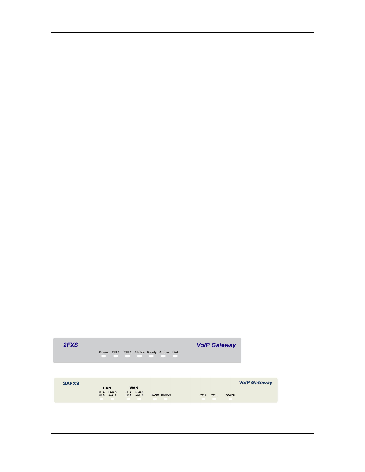
1.4 Front Panels
The LEDs on the front panel indicate the operational status of the Gateway.
Figure 1-1 2FXS Gateway Front Panel
Page 15
FXS Gateway Overview
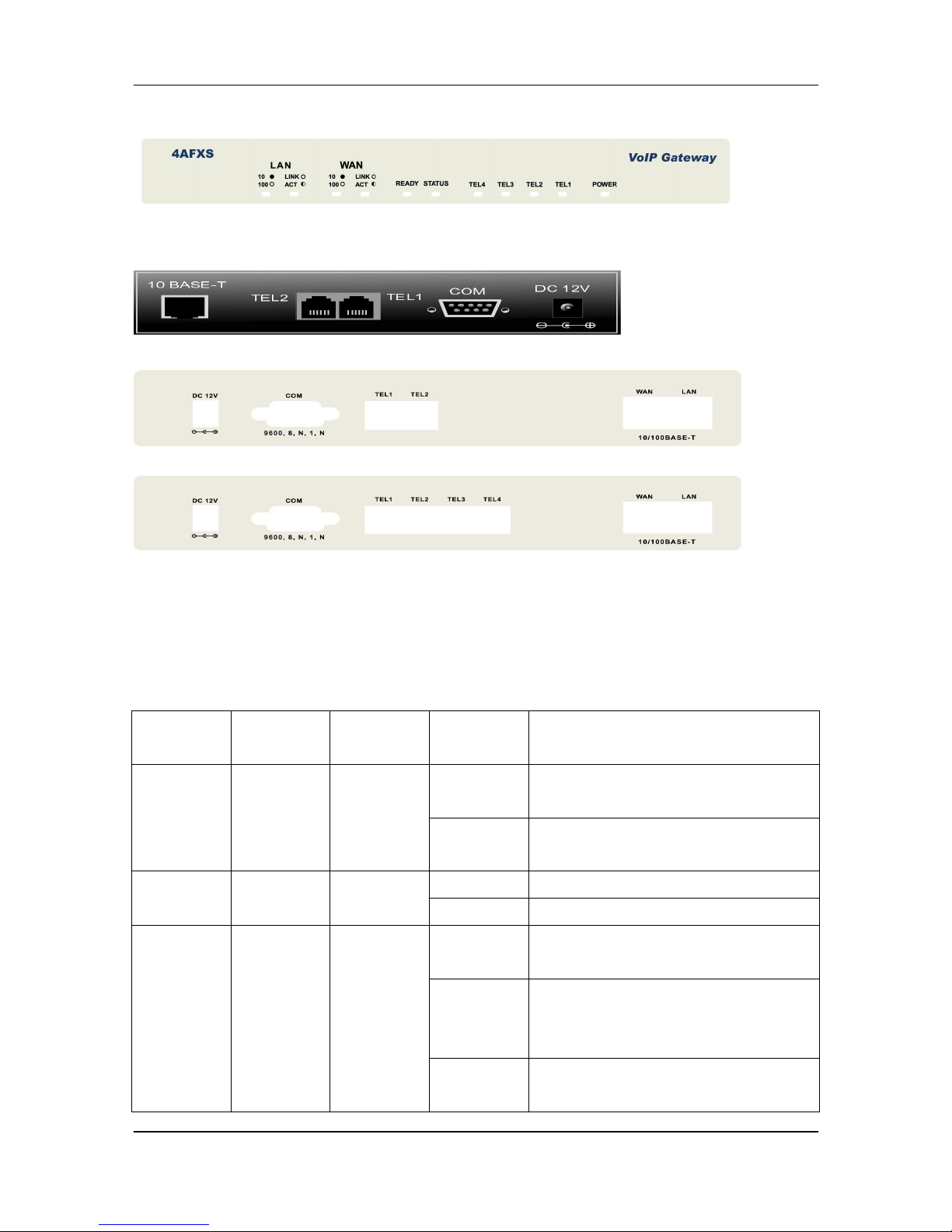
- 4 -
Figure 1-2 2AFXS Gateway Front Panel
Figure 1-3 4AFXS Gateway Front Panel
1.5 Back Panel Ports
Figure 1-4 2FXS Gateway Back Panel Ports
Figure 1-5 2AFXS Gateway Back Panel Ports
Figure 1-6 4AFXS Gateway Back Panel Ports
1.6 Hardware Specifications
These are the hardware details of the 2FXS, 2AFXS, 4AFXS.
1.6.1 2FXS LEDs
The following table describes the LED functions:
Table 1-1 2FXS LEDs Descriptions
LEDs Functions Indicator
Status
Active Description
Power Power Green On The Power adapter is connected to
the Gateway.
Off The system is off or not receiving
power.
TEL (1-2) TEL Red On The Telephone is Off-Hook.
Off The Telephone is On-Hook.
Status Status Green Off The FXS Gateway is under
Peer-to-Peer Mode.
On The FXS Gateway has successfully
registered to Proxy when it is under
Proxy mode.
Blinking The FXS Gateway is not registered
to Proxy when it is in Proxy mode.
Page 16

FXS Gateway Overview
- 5 -
LEDs Functions Indicator
Status
Active Description
The FXS Gateway is in downloading
mode.
Ready Ready Green Slow
Blinking
The FXS Gateway is in normal
mode.
Fast
Blinking
The FXS Gateway is in downloading
mode.
Active Blinking Ethernet data is being
transmitted/received.
Link LAN Green On The FXS Gateway is physically
connected to the Ethernet correctly.
Off The 10M LAN is not connected.
1.6.2 2AFXS LEDs
The following table describes the LED functions:
Table 1-2 2AFXS LEDs Functions
LEDs Functions Indicator
Status
Active Description
LAN Switch to another device, such as
PC
Link/ACT Link/ACT Green Blinking While plugging on the Ethernet
cable, it mu
st light on and the flash if
some data is being TX/RX.
OFF The Ethernet cable is not connected.
10/100M LAN Green Off The 10M LAN is connected.
On The 100M LAN is connected.
WAN Uplink to the HUB/Router directly.
Link/ACT Link/ACT Green Blinking While plugging on the Ethernet
cable, it must light on and the flash if
some data is being TX/RX.
OFF The Ethernet cable is not connected.
10/100M WAN Green Off The 10M WAN is connected.
On The 100M WAN is connected.
Ready Ready Green Slow
Blinking
The FXS Gateway is in normal
mode.
Fast
Blinking
The FXS Gateway is in downloading
mode.
Page 17

FXS Gateway Overview
- 6 -
LEDs Functions Indicator
Status
Active Description
Status Status Green Off The FXS Gateway is in Peer-to-
Peer
Mode.
On The FXS Gateway has successfully
registered to Proxy when it is in
Proxy mode.
Blinking The FXS Gateway is not registered
to Proxy when it is in Proxy mode.
The FXS Gateway is in downloading
mode.
TEL(1-2) TEL Red On The Telephone is Off-Hook.
Off The Telephone is On-Hook.
Power Power Green On The Power adapter is connected to
the Gateway.
Off The system is off or not receiving
power.
1.6.3 4AFXS LEDs
Table 1-3 LEDs Functions
LEDs Functions Indicator
Status
Active Description
LAN Switch to another device, such as
PC
Link/ACT Link/ACT Green Blinking While plugging on the Ethernet
cable, it must light on and the flash if
some data is being TX/RX.
OFF The Ethernet cable is not connected.
10/100M LAN Green Off The 10M LAN is connected.
On The 100M LANis connected.
WAN Uplink to the HUB/Router directly.
Link/ACT Link/ACT Green Blinking While plugging on the Ethernet
cable, it must light on and the flash if
some data is being TX/RX.
OFF The Ethernet cable is not connected.
10/100M WAN Green Off The 10M WAN is connected.
On The 100M WAN is connected.
Ready Ready Green Slow The FXS Gateway is in normal
Page 18
FXS Gateway Overview
- 7 -
LEDs Functions Indicator
Status
Active Description
Blinking mode.
Fast
Blinking
The FXS Gateway is in downloading
mode.
Status Status Green Off The FXS Gateway is in Peer-to-
Peer
Mode.
On The FXS Gateway has successfully
registered to Proxy when it is in
Proxy mode.
Blinking The FXS Gateway is not registered
to Proxy when it is in Proxy mode.
The FXS Gateway is in downloading
mode.
TEL(1-4) TEL Red On The Telephone is Off-Hook.
Off The Telephone is On-Hook.
Power Power Green On The Power adapter is connected to
the Gateway.
Off The system is off or not receiving
power.
1.6.4 Back Panel Port
Ethernet Port:
Ethernet port is for connecting VoIP Gateway to network, transmit rate supports
10/100 Base-T.
Ethernet connector(LAN)
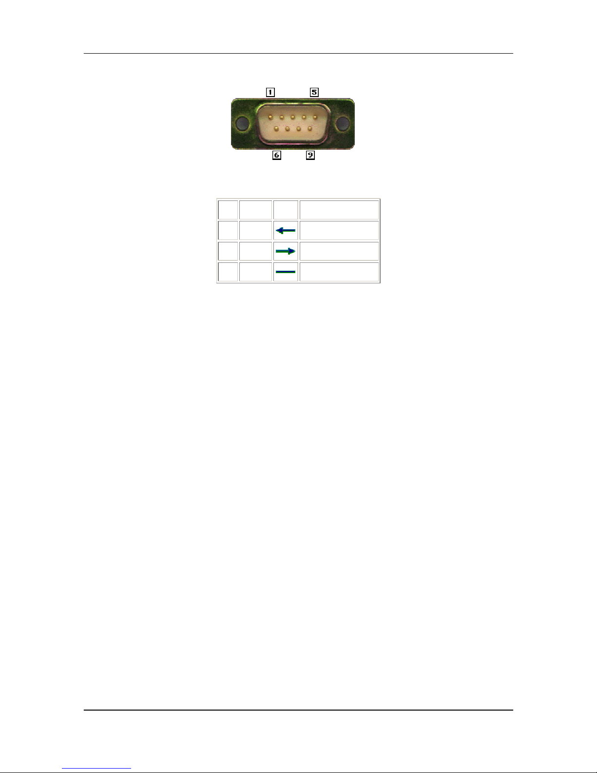
COM Port:
RS232 console port (DB-9pin male connector)
Page 19
FXS Gateway Overview
- 8 -
Note: use straightforward cable to connect to your computer.
PINOUTS
Pin Name Dir Description
2 RXD
Receive Data
3 TXD
Transmit Data
5 GND
System Ground
TEL Port:
TEL Port:
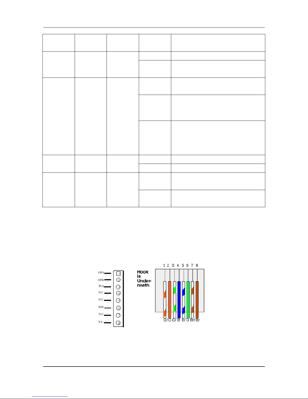
RJ-11 connector, FXS interface. To connect analog phone sets or trunk line of
PABX.
12V DC Port:
DC Power supply.
1.6.5 Back Panel Connections
This section outlines how to connect your VoIP Gateway to the LAN and the WAN.
In the case of connecting a Cable Modem you must connect the coaxial cable from
your cable service to the threaded coaxial cable connect on the back of the cable
modem.
Step 1. Connecting the Console Port
For the initial configuration of your VoIP Gateway, you need to use terminal
emulator software on a workstation and connect it to the VoIP Gateway the console
port. Connect the 9-pin end of the console cable to the console port of the VoIP
Gateway and the other end to a serial port (COM1, COM2 or other COM port) of your
workstation. You can use an extension RS-232 cable if the enclosed one is too short.
After the initial setup, you can modify the configuration remotely through telnet
connections.
Step 2. Connect the VoIP Gateway to the WAN port
Connect the WAN port (silver) on the VoIP Gateway to the Ethernet port on the
cable modem using the cable that came with your cable modem. The Ethernet port on
the cable modem is sometimes labeled “PC” or “Workstation”.
Step 3. Connecting the PC to the LAN
Page 20

FXS Gateway Overview
- 9 -
If you have more than one PC, you must use an external hub. Connect the
10/100M LAN Port (gold) on the VoIP Gateway to a port on the hub using a straight
through Ethernet cable. If you only have one PC, you can connect the VoIP Gateway
to the PC directly without a hub. For a single PC, connect the 10/100M LAN port on the
VoIP Gateway to the Network Adapter on the PC using a crossover cable (red tag).
Step 4. Connecting the Power Adapter to your VoIP Gateway
Connect the power adapter to the port labeled POWER on the rear panel VoIP
Gateway.
Caution: To prevent damage to the VoIP Gateway, first make sure you have the
correct AC power adapter. Please see the Appendices for AC power adapter
specifications for your region.
Step 5. Grounding the VoIP Gateway
If you want to ground the VoIP Gateway then connect a grounded wire to the F.G.
(Frame Ground) of the VoIP Gateway.
1.7 Additional Installation Requirements
In addition to the contents of your package, there are other hardware and
software requirements you need before you can install and use your VoIP Gateway.
These requirements include:
1. A computer with an Ethernet NIC (Network Interface Card) installed.
2. A computer equipped with communications software configured to the following
parameters:
VT100 terminal emulation.
9600 Baud.
No parity, 8 Data bits, 1 stop bit, Flow Control set to None.
3. Use Internet Explorer 5.5 and later or Netscape Navigator 6 and later versions.
4. Analog telephone set
5. Software tools: Gatekeeper (optional)
After the VoIP Gateway is properly set up, you can make future changes to the
configuration through telnet connections
1.8 Setting Up the TCP/IP Protocol
If you are not sure whether the TCP/IP Protocol has been installed, follow these
setups to check, and if necessary, install TCP/IP onto your PCs.
Step 1. Click the [Start] button, Choose [Settings], then [Control Panel]. Double-click
the [Network] icon. Your Network window should appear as follows.
Step 2. Select the [Configuration] tab.
Import:
For Windows 2000 & Windows XP Setting, you will find that they differs with
Windows 98/ME/NT slightly. See the Following for reference.
Page 21

FXS Gateway Overview
- 10 -
Click the “Local Area Connection” icon on the lower right hand side of your
desktop screen.
In the [Local Area Connection Status] windows, click the [Properties] button
the your Network windows will appear.
There is only one tab, [General], in the Network window.
Step 3. Click whether the TCP/IP Protocol has already been installed onto your
computer’s Ethernet card. Note that TCP/IP Protocol an be installed for a
computer’s Dial-Up Adapter as well as for the Ethernet cad.
- If yes, go to set 7.
- If no, click the [Add] button
Step 4. Double-click [Protocol] in the Select Network Component Type or highlight
[Protocol] then click [Add].
Step 5. Highlight [Microsoft] under the list of manufactures
Step 6. After a new second, you will be returned to the Network window. The TCP/IP
Protocol should now be on the list of installed network components.
Step 7. Click the [Properties] button. The TCP/IP Properties windows consist of
several tabs. Choose the [IP Address] tab.
Step 8. Select [Specify an IP Address] and enter [10.1.1.1] in the [IP Address]
location (where xxx is a number between 2 and 254 used by the VoIP Gateway to
identify each computer), and the default [Subnet Mask: 255.0.0.0]. Note than no
two computers on the same LAN can have the same IP address.
Step 9. Click on the [DNS Configuration] tab and select [Enable DNS]. Then click the
[Add] button.
Step 10. Click on the [Gateway] tab and enter the High-Performance VoIP Gateway
default gateway value 10.1.1.254 in the [new gateway] field, then click [Add]
Button.
Step 11. Click [OK] button, Restart your PC to complete the TCP/IP installation.
1.9 Power Up Your VoIP Gateway
At this point, you should have connected the console port, the LAN Port, the WAN
port and the power port to the appropriate devices or lines. Plug the power adapter into
a wall outlet. The Power LED should be on. The Status LED will come on after the
system tests are complete. The WAN LED and one of the LAN LEDs come on
immediately after the Status LED come on, if connections have been made to the LAN
and WAN ports.
Page 22
FXS Gateway Overview
- 11 -
Part II:
Web Configuration with FXS Gateway
This part tells how to access and navigate the web configuration and perform initial
configuration. It also describes the Getting Started web configuration when you use the
FXS Gateway.
Page 23
FXS Gateway Overview
- 12 -
Chapter 2
Web Configuration with FXS Introduction
This Chapter describes how to login into the WEB and navigate through it.
2.1 Web Configuration with FXS Overview
The embedded web configuration allows you to use a web browser to manage the
FXS Gateway.
2.2 Accessing the Web Configuration
You will need a computer with and Ethernet 10BaseT, 100Base-TX Network Interface
Card (NIC). Connect to the LAN port in the FXS.
Use Internet Explorer 5.5 and later or Netscape Navigator 6 and later versions.
Use the following instructions to login on to the web configuration.
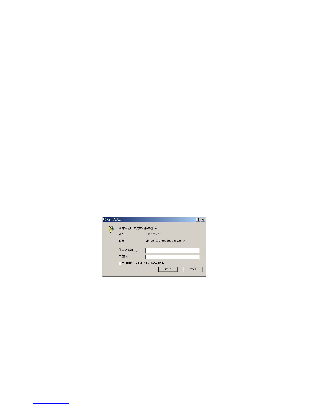
2.3 Login and welcome screen
Step 1. Start your web browser.
Step 2. Launch your web browser and enter [10.1.1.3] (the default IP address of the
FXS Gateway) in the Location or Address field. Press Enter.
Step 3. The Password screen now appears. Please type [root] in the user name
field, (it may display automatically for you) and your password (default [Null]) in
the password field.
Step 4. Click OK.
Figure 2-1 Login Screen
Step 5. After a successful login, you will see the welcome screen show next.
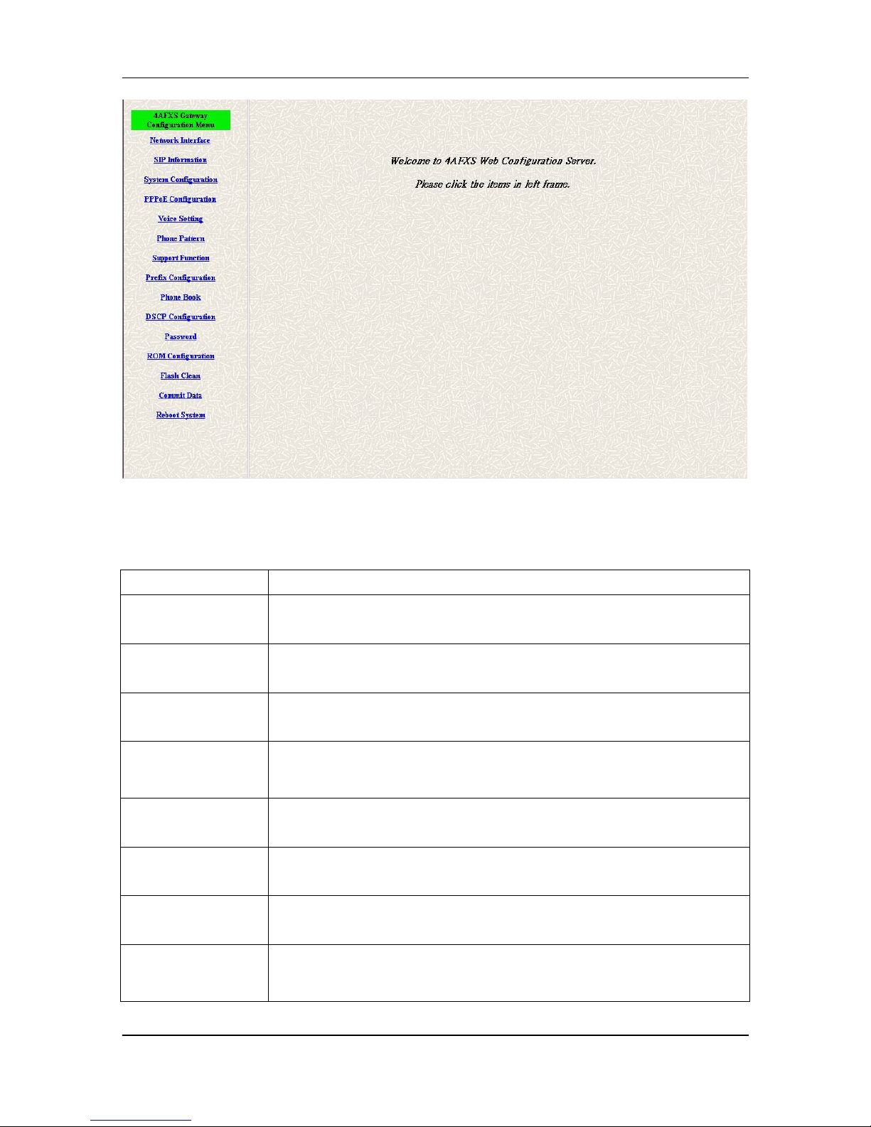
2.4 Welcome Screen
This is the web configuration welcome screen. Click a link on the navigation panel
to go to the corresponding screen.
Page 24
FXS Gateway Overview
- 13 -
Figure 2-2 FXS Gateway web configuration welcome screen
The following table describes the screen.
Table 2-1 Navigation Panel Links
LABEL DESCRIPTION
Network Interface This link takes you to a screen where you can configure the FXS
Gateway Network Interface Information.
SIP Information This link takes you to a screen where you can setup up SIP
Information.
System
Configuration
This link takes you to a screen where you can set up System
Configuration.
PPPoE
Configuration
This link takes you to a screen where you can set up PPPoE
Configuration.
Voice Setting This link takes you to a screen where you can set up Voice
Configuration.
Phone Pattern This link takes you to a screen where you can set up Phone
Pattern
Configuration.
Support Function This link takes you to a screen where you can set up Support
Functions Configuration.
Prefix Configuration This link takes you to a screen where you can set up Prefix
Configuration.
Page 25
FXS Gateway Overview
- 14 -
LABEL DESCRIPTION
Phone Book This link takes you to a screen where you can set up Phone Book
Information.
DSCP Configuration This link takes you to a screen where you can set up DSCP
Configuration.
Password This link takes you to a screen where you can change passwords.
ROM Upgrade This link takes you to a screen where you can change ROM
Upgrade configuration.
Flash Clean This link takes you to a screen where you can click flash memory
information and configuration.
Commit Data This link takes you to a screen where you can click save your
changes to the non-volatile memory.
Reboot System This link takes you to a screen where you can click to reboot FXS
Gateway.
2.5 Saving Your Configuration
Click [OK] to save your changes back to the VoIP Gateway volatile memory. The
VoIP Gateway loses these changes if it is turned off or loses power, so use the
[Commit Data] link on the navigation panel to the left to save your changes to the
non-volatile memory when your are done configuring.
2.6 Navigating the Web Configurator
The web configuration uses one level. For example, to configure [Network
Interface], click the link on the navigation panel to open the configuration screen.
Page 26

FXS Gateway Overview
- 15 -
Figure 2-3 Network Interface Screen
Page 27
FXS Gateway Overview
- 16 -
Chapter 3
Initial Configuration
This Chapter covers the basic configuration needed to set up and use the FXS
Gateway. Refer to the other part describes about individual fields within screens.
3.1 Initial Configuration Overview
This chapter describes the procedure for the initial configuration of the VoIP
Gateway. Refer to the relevant chapters in this User’s Guide for descriptions of the
fields and buttons within individual screens.
3.2 General Configuration
The FXS Gateway is with a default IP address of 10.1.1.3 and a subnet mask of
255.0.0.0.
3.3 Static IP address
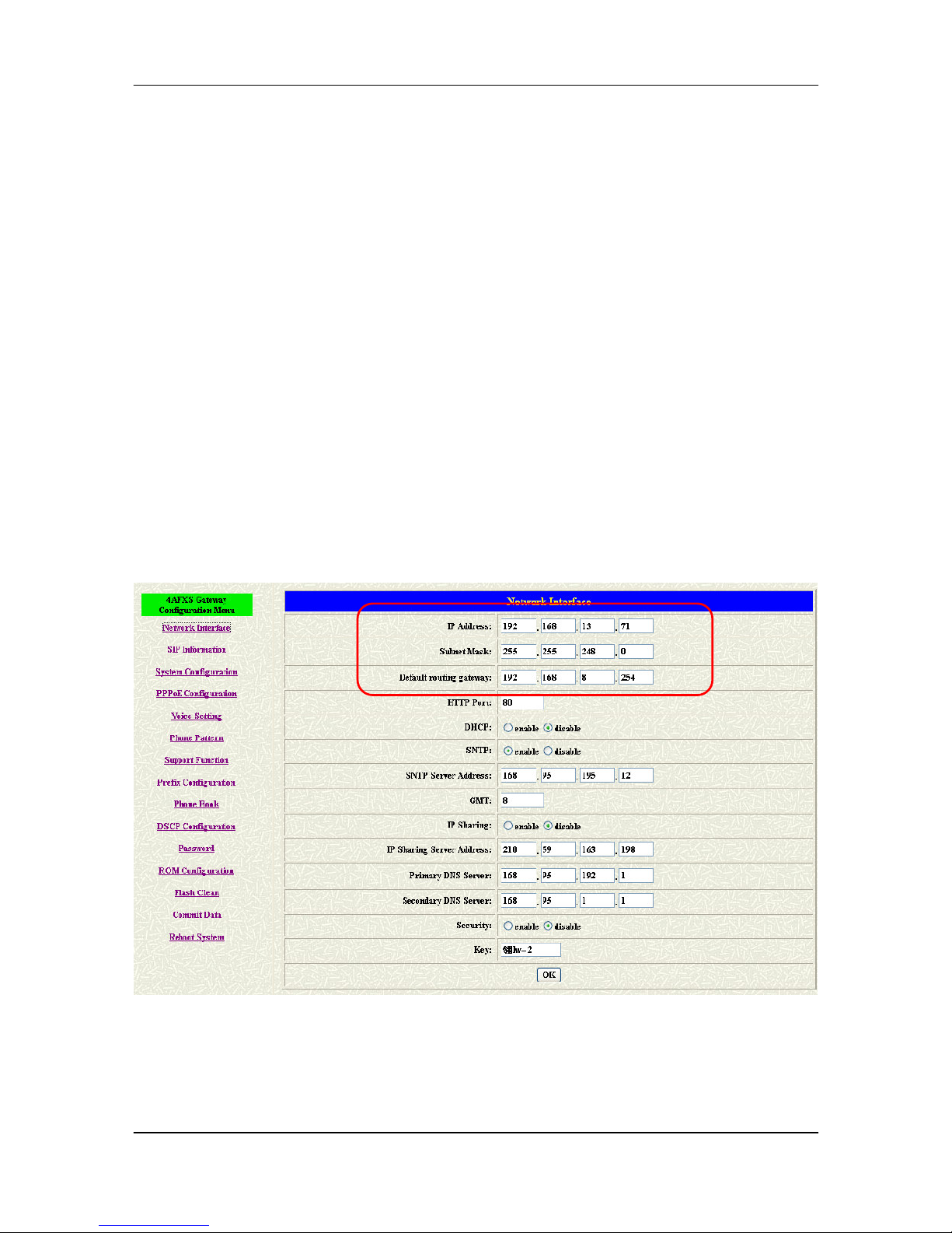
Step 1. Configure the IP address of this unit. Click [Network Interface] on the
navigation panel. In the Network Interface screen, type a new IP address, subnet
mask and the default routing gateway (e.g. IP Address: 192.168.13.4, Subnet
mask: 255.255.248.0, Default routing gateway: 192.168.8.254) and click the OK
button.
Figure 3-1 Network Interface
Step 2. Click [Commit Data] on the navigation panel. In the Commit Configuration
Data screen, click the [Commit] button.
Page 28
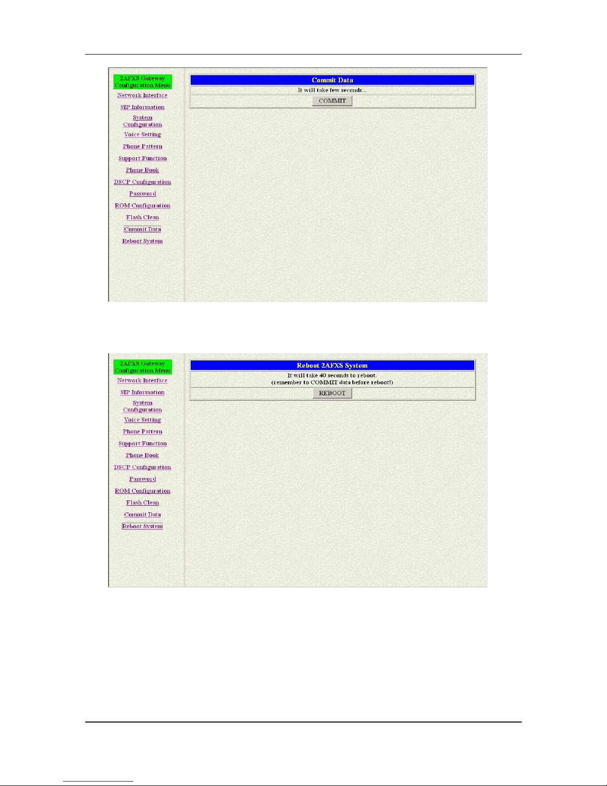
FXS Gateway Overview
- 17 -
Figure 3-2 Commit Configuration Data
Step 3. Click [Reboot System] on the navigation panel. In the FXS Gateway screen,
click the [Reboot] button. It will take 40 seconds to reboot.
Figure 3-3 Reboot FXS System
Step 4. Close the current browser windows and launch your web browser again.
Enter the new IP address in the Location or Address field.
3.4 DHCP mode
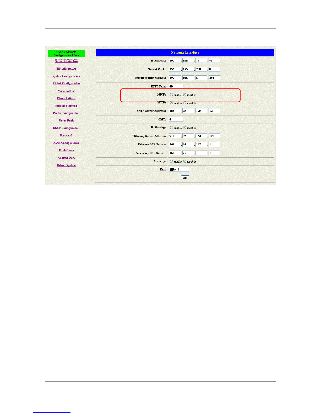
Step 1. Configure the FXS Gateway IP mode to DHCP Mode. Click [Network
Interface] on the navigation panel. In the Network Interface screen, enable the
DHCP function if you are using the cable modem or DHCP server and click the
Page 29
FXS Gateway Overview
- 18 -
[OK] button.
Figure 3-4 Network Interface
Step 2. Click [Commit Data] on the navigation panel. In the Commit Configuration
Data screen, click the Commit button.
Step 3. Click [Reboot System] on the navigation panel. In the FXS Gateway screen,
click the [Reboot] button. It will take 40 seconds to reboot.
Step 4. Close the current browser windows and launch your web browser again.
Enter the new IP address in the Location or Address field.
3.5 IP Sharing Configuration
3.5.1 One Sets FXS Gateway
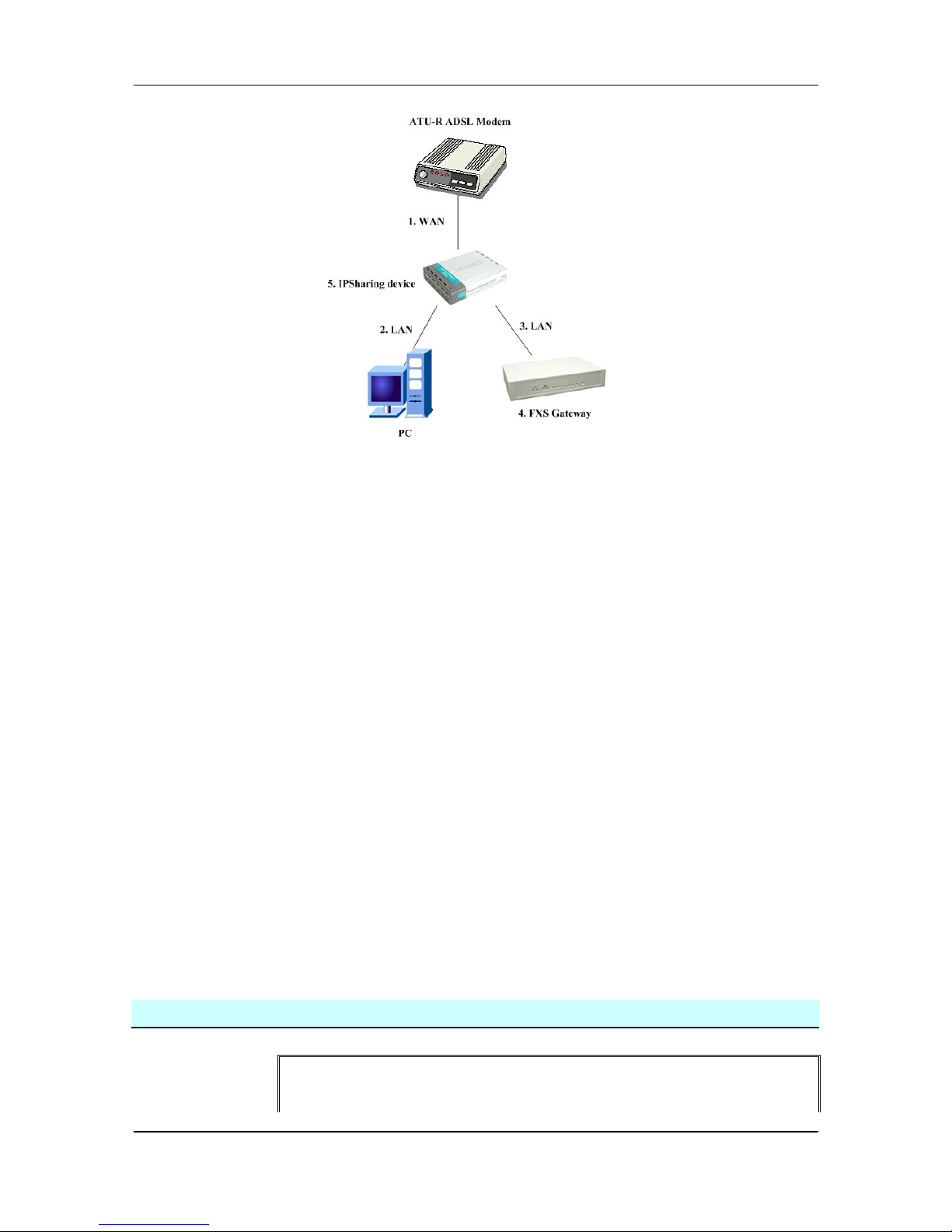
The function is only for the user who is using the IP Sharing device. It is meaning
that Gateway is connected to the IP Sharing device.
The IP Sharing Device must support the DMZ or Virtual server functions
An e.g. such as ADSL network is in the following.
Page 30
FXS Gateway Overview
- 19 -
Step 1. The WAN IP Address obtained from ADSL has two kinds of methods. One is
fixed IP Address, while user applies for one or more fixed IP Addresses. Another
is dynamic IP Address while user applies for dial-up connection way.
Step 2. The LAN IP Address of User’s PC can be set as DHCP client in order to gain
a valid one.
Step 3. One can also assign a fixed IP address, which belongs to the same network
segment as the LAN interface of IP Sharing device.
Step 4. FXS Gateway must enable the IP Sharing function for the fixed / dynamic
WAN IP Address.
Note:
For the Dynamic WAN IP Address, a valid Proxy for FXS Gateway to get
registration on is a necessary. On the other words, it is not workable in
Peer-to-Peer mode while your IP sharing device is under dynamic WAN IP
Address.
Step 5. IP Sharing device must have a function to do IP/Port mapping. Some is
named as DMZ; some is named as virtual server whatever. The VoIP messages
from WAN have to completely pass forward to the LAN. It is said if the FXS
Gateway is assigned a virtual fixed IP Address such as 192.168.1.5, IP Sharing
device must forward the VoIP message to 192.168.1.5.
Please see following for example:
>Advanced setting > NAT setting > DMZ Host setting
DMZ Host setting
▣▣▣▣ Activate DMZ
Page 31
FXS Gateway Overview
- 20 -
DMZ Host IP: 192.168.1.5
Step 6. Configuring the FXS Gateway IP address for IP Sharing Mode. Click
[Network Interface] on the navigation panel. In the Network Interface screen, enter
the IP address, Subnet mask and the default gateway in the network table. Please
follow up your IP Sharing device
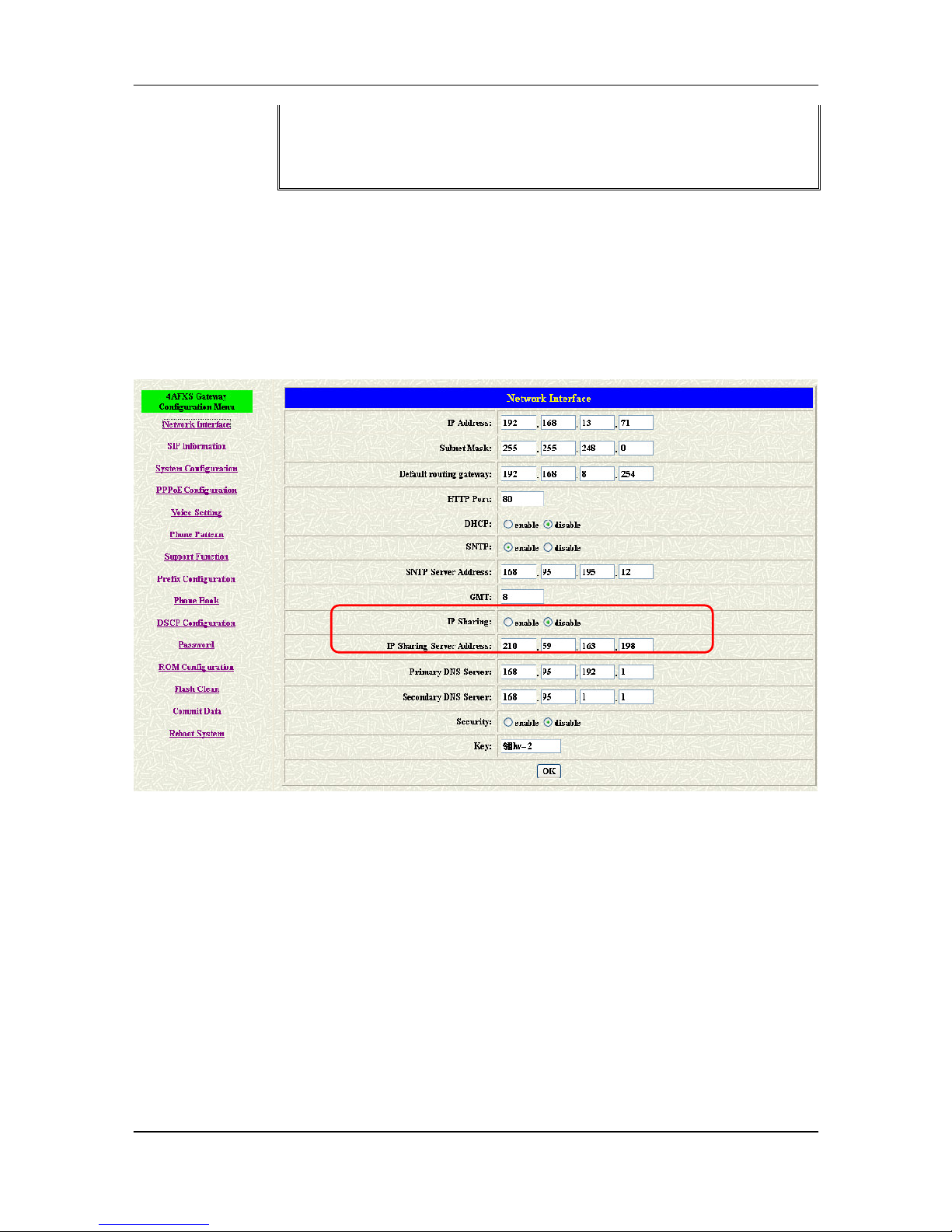
Step 7. Enable the IP sharing function and put the static IP address in the IP Sharing
server address (e.g. 210.59.163.198) and click the OK button.
Figure 3-5 Enable the IP sharing function
Step 8. Click [Commit Data] on the navigation panel. In the Commit Configuration
Data screen, click the Commit button.
Step 9. Click [Reboot System] on the navigation panel. In the VoIP Gateway screen,
click the [Reboot] button. It will take 40 seconds to reboot.
Step 10. Close the current browser windows and launch your web browser again.
Enter the new IP address in the Location or Address field.
Page 32
FXS Gateway Overview
- 21 -
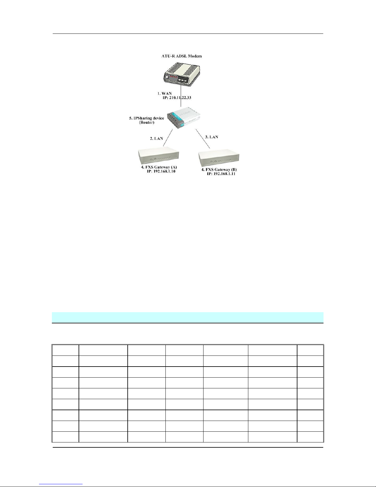
3.5.2 Two sets attached to IP Sharing Device(Router)
1. Assign an IP address to each set using DHCP or fixed address.
2. Enable the IP Sharing function for each set using following command.
Fixed IP Address – usr/config$ ifaddr –ipsharing 1 210.11.22.33
3. Configure separate SIP port and RTP port for each set to prevent from port
conflict. For example, if set A uses the default settings (SIP port: 5060, RTP port:
16384), you must change set B’s setting to SIP port equal to 5061 and RTP port
equal to 26384 for instance.
Change SIP port – usr/config$sip –port 5061
Change RTP port– usr/config$sip –rtp 26384
4. Use the Port Forwarding or Port Redirection function provided by IP Sharing
device (Router). See following for example.
>Advanced setting > NAT setting > Port Redirection
Active Configuration
Items Service name Protocol Actual Port
Virtual IP Virtual Port Enable
1
1 UDP 5060 192.168.1.10
5060
V
2
2 UDP 16384 192.168.1.10
16384
V
3
3 UDP 16394 192.168.1.10
16394
V
4
4 UDP 5061 192.168.1.11
5061
V
5
5 UDP 26384 192.168.1.11
26384
V
6
6 UDP 26394 192.168.1.11
26394
V
7
--- 0 0 X
8
--- 0 0 X
Page 33

FXS Gateway Overview
- 22 -
9
--- 0 0 X
10
--- 0 0 X
Note:
With Dynamic WAN IP Address, when the WAN IP is changed, we need to
change the external IP of FXS Gateway using above command.
1. Different Vendor’s Router will have different appearance of setting.
2. Once you set the DMZ Host, you don’t need to configure the Port Forwarding
and vice versa.
3. If there is only one FXS Gateway attached to the IP Sharing device, it is
recommanded to use DMZ Host setting to enable the NAT traverse and
disable the Port Forwarding.
4. If there are two or more sets of FXS Gateway attached to the IP-Sharing
device, please configure the Port Redirection (Forwarding) to enable the NAT
traverse and disable the DMZ Host.
5. After the IP Sharing configuration of FXS Gateway and IP Sharing device is
complete, you must reboot the FXS Gateway to activate the new settings.
Page 34
FXS Gateway Overview
- 23 -
Chapter 4
Making a VoIP Call
This Chapter covers the basic configuration the gateway for making VoIP calls. One is
the Peer-to-Peer mode, Proxy routed mode and Gateway mode. The configurations
and functions are different. Please make sure about the mode you want and follow up
the step to configure your gateway.
4.1 Configure the gateway into the Peer-to-Peer mode
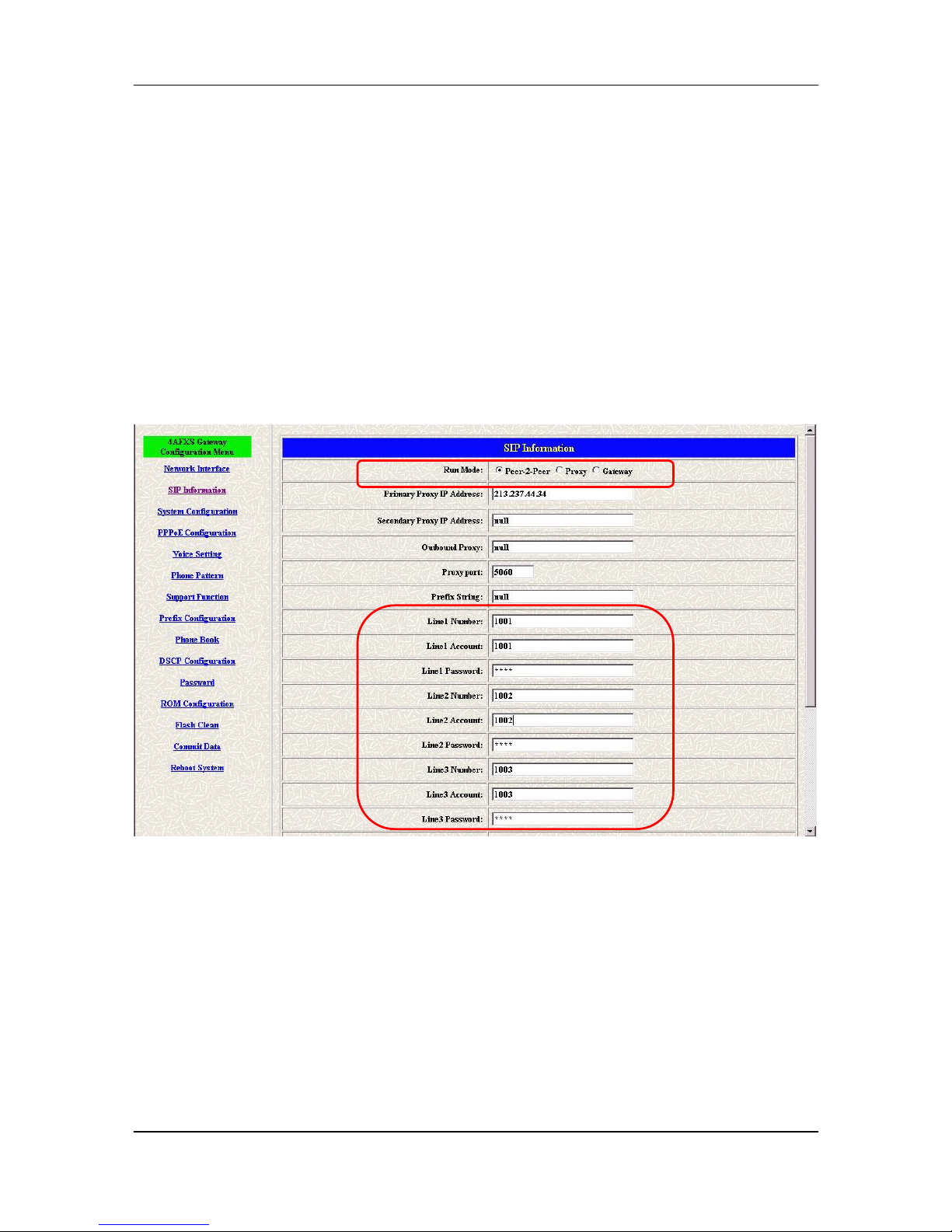
Step 1. Configure the FXS Gateway SIP information. Click [SIP information] on the
navigation panel. In the SIP information screen, select Peer-to-Peer Mode
function, set line number (e.g. Line1 Number 1001, Line2 Number: 1002) and
click the [OK] button.
Figure 4-1 SIP Configuration – Peer to Peer mode Screen
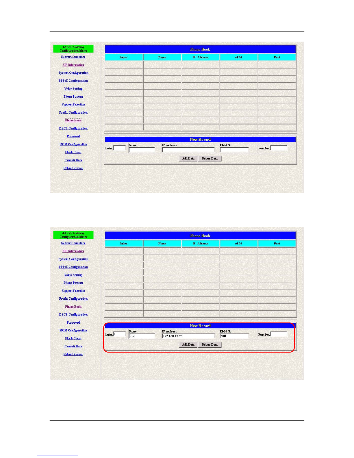
Step 2. Configure the FXS Gateway Phone Book. Click [Phone Book] on the
navigation panel. In the Phone Book screen, enter the Index, Name, IP address
and e164 (phone number) of the destination and click the Add Data button.
Page 35
FXS Gateway Overview
- 24 -
Figure 4-2 Phone Book
Step 3. E.g. enter the Index: 1, Name: test, e164 No.: 608, IP address: 192.168.13.75
and of the destination and click the [Add Data] button.
Figure 4-3 Phone Book – New Record
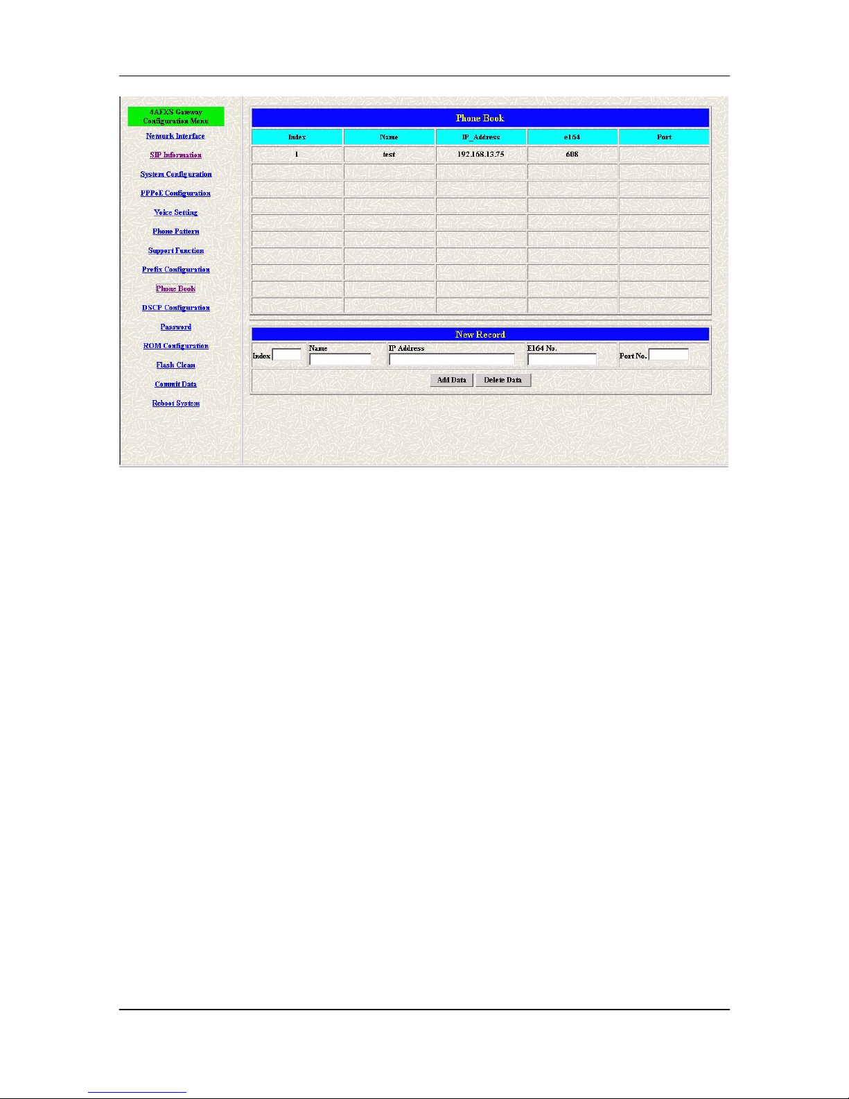
Step 4. Phone Book list will display the first index.
Page 36
FXS Gateway Overview
- 25 -
Figure 4-4 Phone Book
Step 5. Click [Commit Data] on the navigation panel. In the Commit Configuration
Data screen, click the [Commit] button.
Step 6. Click [Reboot System] on the navigation panel. In the FXS Gateway screen,
click the [Reboot] button. It will take 40 seconds to reboot.
4.2 Configure the gateway into the Proxy routed mode
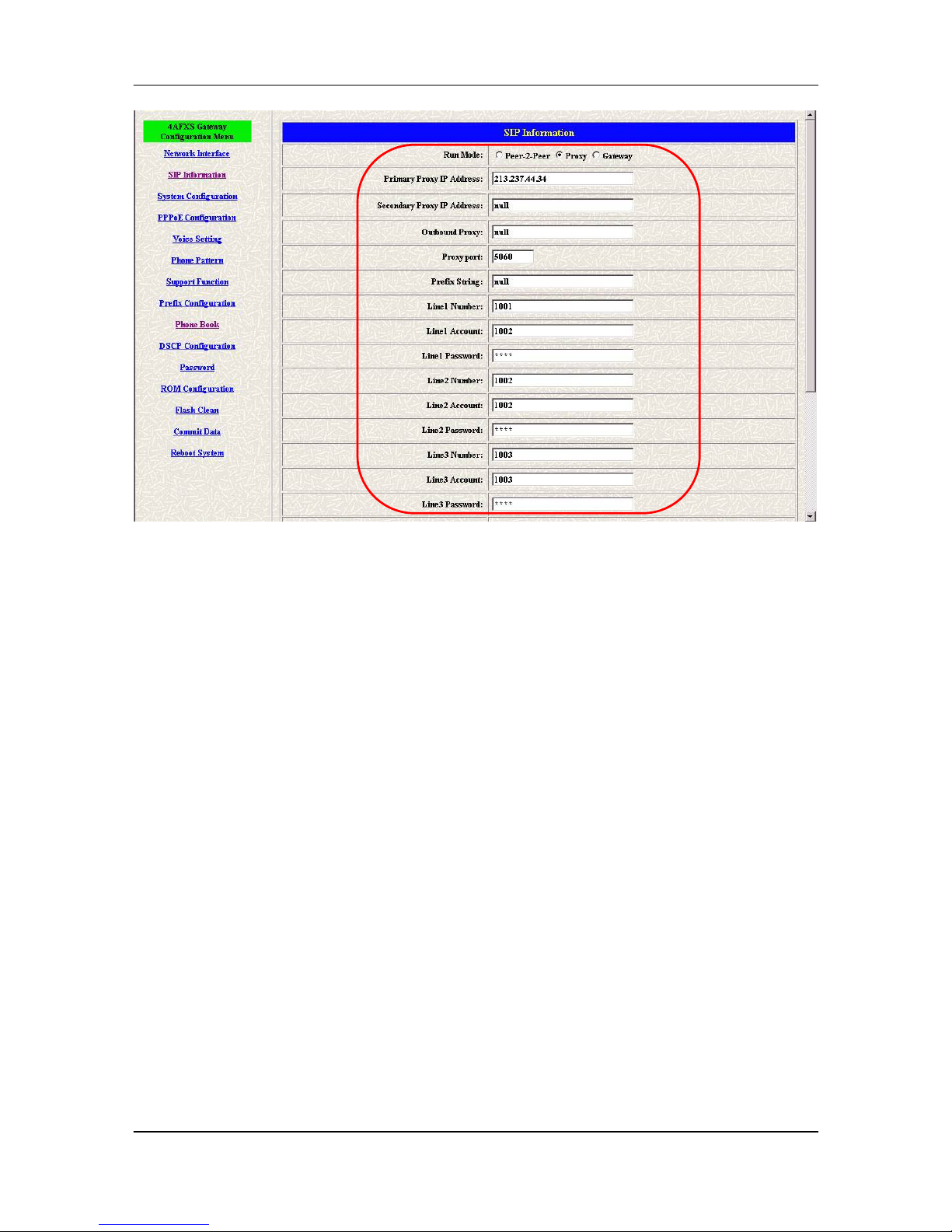
Step 1. Configure the FXS Gateway SIP Configuration. Click SIP Information on the
navigation panel. In the SIP Information screen, select Proxy routed Mode
function.
Step 2. To change the SIP information from your service provider Proxy IP Address,
Line1 Number, Line1 Account, Line1 Password, (e.g. Proxy IP Address:
192.168.14.155, (e.g. Line1 Number: 1001, Line1 Account: 1001, Line1 Password:
1001, Line2 Number: 1001, Line2 Account: 1001, Line2 Password: 1001), and
click the OK button.
Page 37
FXS Gateway Overview
- 26 -
Figure 4-5 Configure the Proxy info
Step 3. Click Commit Data on the navigation panel. In the Commit Data screen, click
the Commit button. In the Commit Data screen to Display Commit to Flash OK!,
When the Commit Data Ok.
Step 3. Click Reboot Data on the navigation panel. In the Reboot FXS System screen,
click the Reboot button. It will take 40 seconds to reboot.
4.3 Configure the gateway into the Gateway routed mode
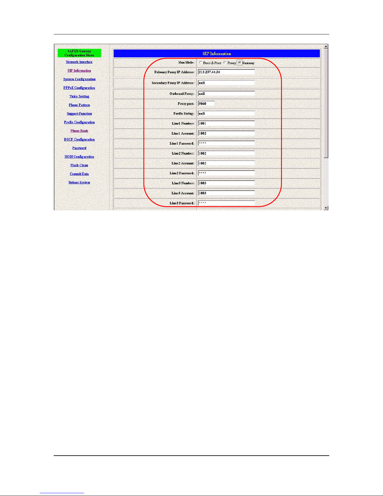
Step 1. Configure the FXS Gateway SIP Configuration. Click SIP Information on the
navigation panel. In the SIP Information screen, select Gateway routed Mode
function.
Step 2. To change the SIP information from your service provider Proxy IP Address,
Line1 Number, Lin1 Account, Line1 Password, (e.g. Proxy IP Address:
192.168.14.155, (e.g. Line1 Number: 6091, Line1 Account: 6091, Line1 Password:
6092), and click the OK button.
Page 38
FXS Gateway Overview
- 27 -
Figure 4-6 Configure the Proxy info
Step 3. Click Commit Data on the navigation panel. In the Commit Data screen, click
the Commit button.
Step 4. Click Reboot Data on the navigation panel. In the Reboot FXS System screen,
click the Reboot button. It will take 40 seconds to reboot.
Page 39
FXS Gateway Overview
- 28 -
Chapter 5
Upgrade ROM Version
This Chapter covers the basic how to upgrade FXS Gateway ROM Version.
5.1 Before you start downloading
Step 1. Please confirm Host PC, which is installed as TFTP / FTP server and device
is in available network.
Step 2. Remember the current configuration, such as [SIP Information], [Phone
Book].
5.2 Update Application Version
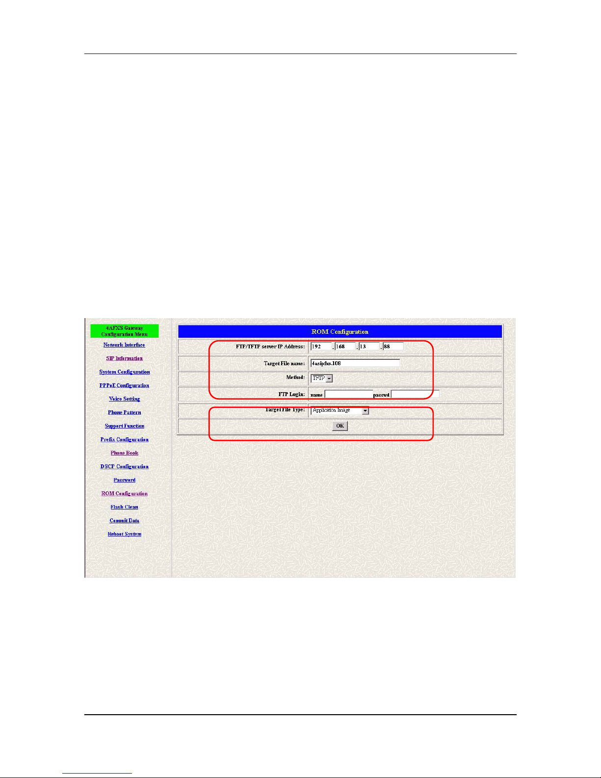
Step 1. Update the FXS Gateway ROM Version. Click [ROM Upgrade] on the
navigation panel. In the [ROM Configuration] screen, type a Server IP address,
Target File Name, Method, Target File Type (e.g. Server IP Address:
192.168.13.88, Target File Name: 4asipfxs.108, Method: TFTP, Target File Type:
Application image) and click the [OK] button.
Figure 5-1 ROM Configuration
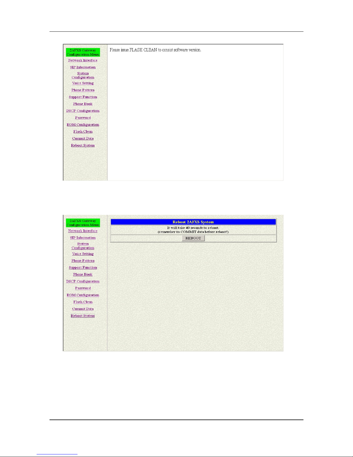
Step 2. When the ROM upgrade is finished. The screen will display [Please issue
FLASH CLEAN to consist software version.] information.
Page 40
FXS Gateway Overview
- 29 -
Figure 5-2 ROM File Upgrade ok
Step 3. Click [Flash Clean] on the navigation panel. In the Flash Clean screen, click
the [CLEAN] button.
Figure 5-3 Flash Clean
Step 4. In the Flash Clean screen to Display [Flash cleaned!! Please reboot your
system!!], When the Flash Clean Ok.
Step 5. Click [Reboot System] on the navigation panel. In the Reboot FXS Gateway
screen, click the [Reboot] button. It will take 40 seconds to reboot.
Step 6. Close the current browser windows and launch your web browser again.
Page 41
FXS Gateway Overview
- 30 -
Enter the IP address in the Location or Address field.
5.3 Update Boot2m Version
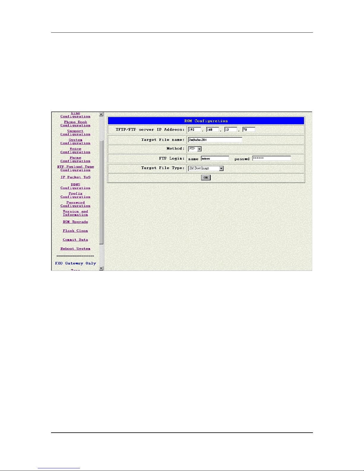
Step 1. Update the FXS Gateway 2mROM Version. Click [ROM Upgrade] on the
navigation panel. In the [ROM Configuration] screen, type a Server IP address,
Target File Name, Method, Target File Type (e.g. Server IP Address: 192.168.4.71,
Target File Name: 2m4afxs.204, Method: FTP, FTP Login name: totoro, passwd:
totoro, Target File Type: 2m Boot image) and click the [OK] button.
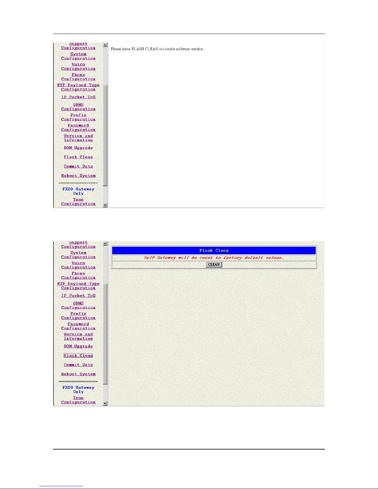
Step 2. When the ROM Upgrade file ok. The screen will display [Please issue FLASH
CLEAN to consist software version.] information.
Page 42
FXS Gateway Overview
- 31 -
Figure 5-4 ROM File Upgrade ok
Step 3. Click [Flash Clean] on the navigation panel. In the Flash Clean screen, click
the [CLEAN] button.
Figure 5-5 Flash Clean
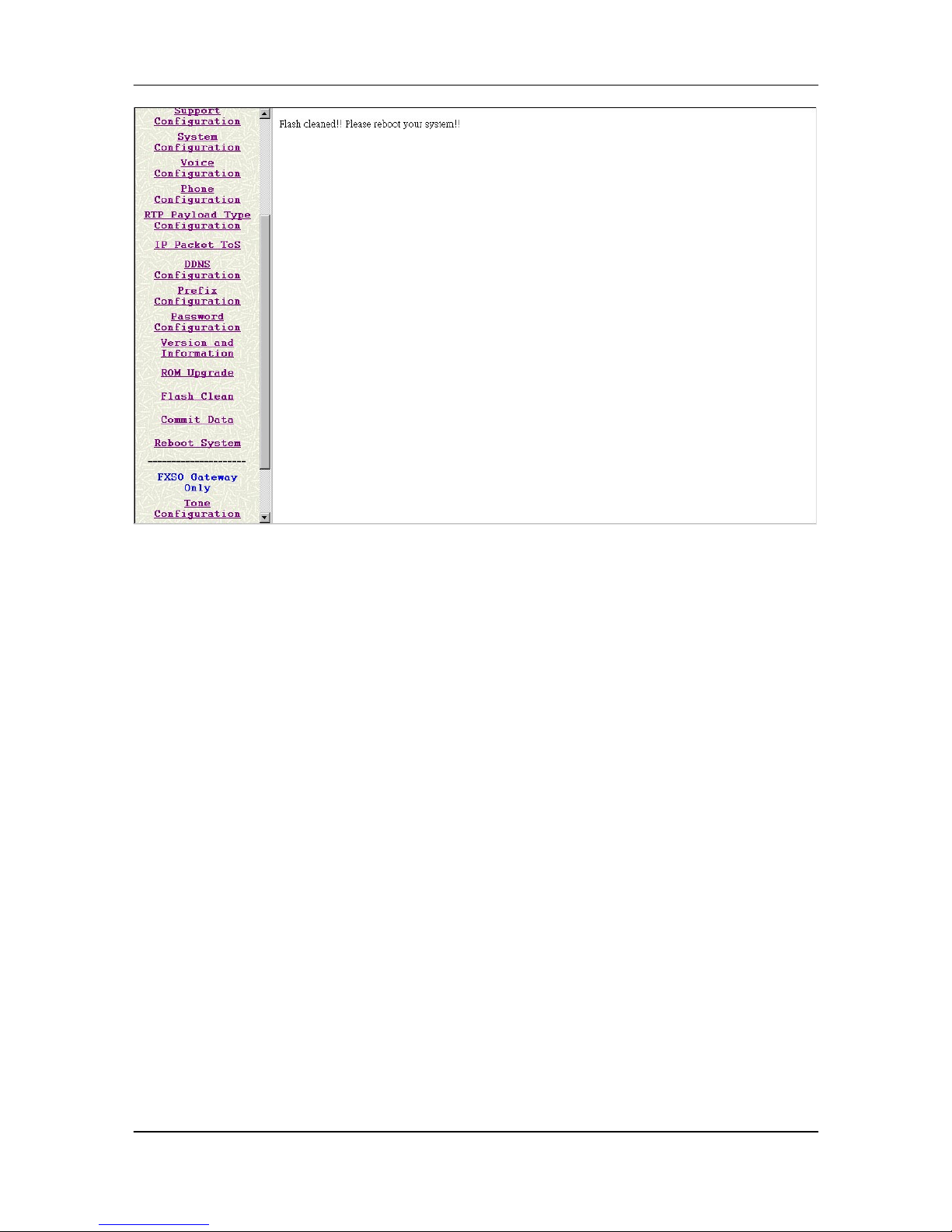
Step 4. In the Flash Clean screen to Display [Flash cleaned!! Please reboot your
system!!], When the Flash Clean Ok.
Page 43
FXS Gateway Overview
- 32 -
Figure 5-6 Flash Clean OK
Step 5. Click [Reboot system] on the navigation panel. In the Reboot FXS Gateway
screen, click the [Reboot] button. It will take 40 seconds to reboot.
Step 6. Close the current browser windows and launch your web browser again.
Enter the IP address in the Location or Address field.
Page 44
FXS Gateway Overview
- 33 -
Chapter 6
Network Interface Screen
This Chapter covers setup Network Interface identification information for FXS
Gateway.
6.1 Network Interface Overview
The web configuration provides Network Interface screen.
6.2 Network Interface Screen
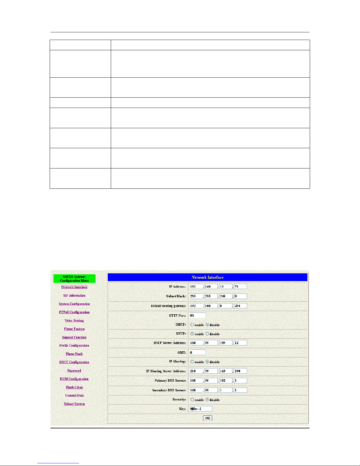
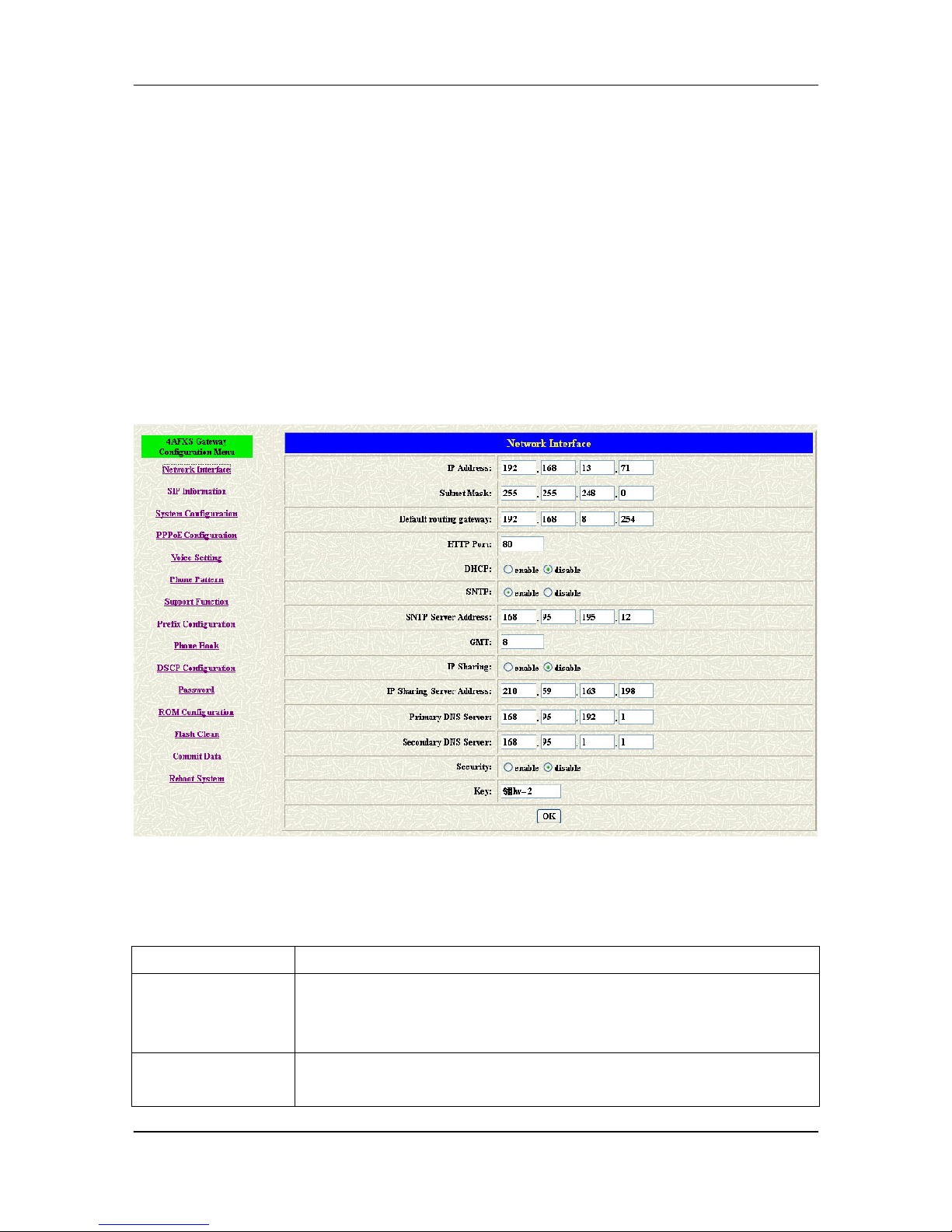
Click [Network Interface] in the navigation panel and open the Network Interface
Screen.
Use this screen to setup Network Interface identification information for the FXS
Gateway.
Figure 6-1 Network Interface
The following table describes this screen.
Table 6-1 Network Interface
LABEL DESCRIPTION
IP Address Enter the IP Address of the FXS Gateway in dotted decimal
notation for e.g. 192.168.13.4. Range of IP Address setting
(0.0.0.0~255.255.55.255).
Subnet Mask E
nter the IP Subnet Mask of your FXS Gateway in dotted decimal
notation for e.g. 255.255.248.0.
Page 45

FXS Gateway Overview
- 34 -
LABEL DESCRIPTION
Default Routing
Gateway
Enter the IP Address of the default-
outgoing gateway of your FXS
Gateway in dotted decimal notation for e.g. 192.168.8.254.
DHCP Select enable/disable Dynamic Host Configuration.
SNTP Select enable/disable Simple Network Time Protocol.
SNTP Server
Address
Set specifies
a SNTP Server as network time source in dotted
decimal notation for e.g. 168.95.192.12.
GMT Set local time zone according to GMT e.g. 8.
IP Sharing
Select enable IP Sharing function, when you specify usage of and
IP Sharing device.
IP Sharing Server
Address
Enter specify a global fixed IP Address, user can add this IP
Address in dotted decimal notation for e.g. 210.11.22.33.
However,
dynamic IP Address is not working in Peer-to-Peer mode.
Primary DNS Server
Enter the DNS IP Address in dotted decimal notation for e.g.
168.95.192.1
Secondary DNS
Server
Enter the DNS secondary IP Address in dotted decimal notation for
e.g. 168.95.1.1
OK [button]
Click [OK] button to save your changes back to the FXS Gateway
volatile memory.
Page 46
FXS Gateway Overview
- 35 -
Chapter 7
SIP Information Screen
This Chapter covers setup SIP related parameters.
7.1 SIP Information Overview
The web configurator provides SIP Configuration screen.
7.2 SIP Information Screen
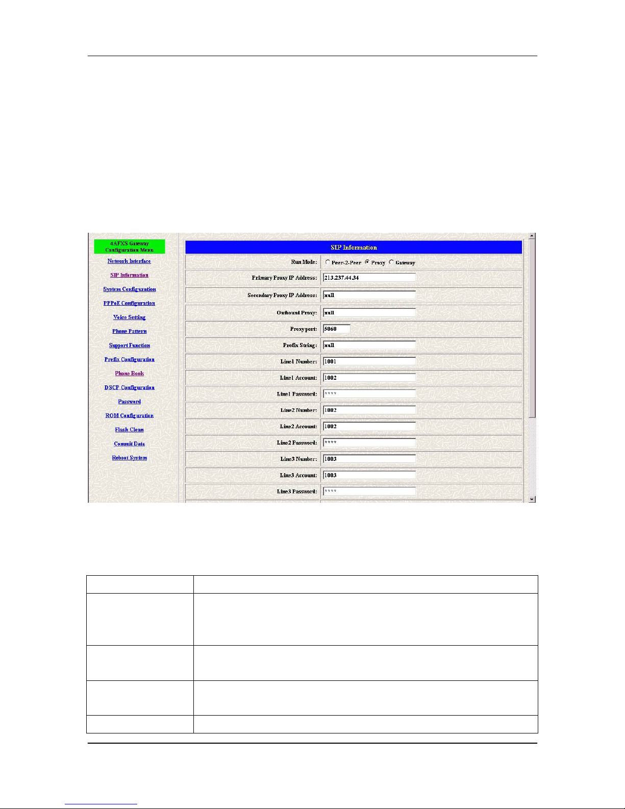
Click [SIP Configuration] in the navigation panel and open the SIP Information
Screen.
Figure 7-1 SIP Information
The following table describes this screen.
Table 7-1 SIP Information
LABEL DESCRIPTION
RUN Mode Select Proxy mode, Gateway mode or Peer-to-Peer mode.
Select Gateway only setting channel 1 line number, account and
password.
Proxy IP Address Set Proxy IP Address in dotted decimal notation e.g.
213.237.44.34.
Second Proxy IP
Address
Set redundancy second 2 Gatekeeper IP Address in dotted decimal
notation.
Outbound Proxy Set IP Address or URL address (Domain Name Server must be
Page 47

FXS Gateway Overview
- 36 -
LABEL DESCRIPTION
configured. Please refer to Network Configure) of outbound Proxy
server.
Proxy Port SIP local UDP port number (5060~5070), default: 5060.
Prefix String Set specific prefix string, use it when User ID contains alphabets.
Line X Number Set Line X Number.
Line X Account Set Line X Account Name.
Line X Password Set Line X Account Password.
SIP Port Set SIP port number, example 5060.
RTP Port Set RTP port number, example 16384.
Expire Used to inform proxy server the valid duration of the registration
information.
OK [button] Click [OK] butto
n to save your changes back to the FXS Gateway
volatile memory.
Page 48
FXS Gateway Overview
- 37 -
Chapter 8
System Configuration Screen
This Chapter covers System Information and configuration.
8.1 System Configuration Overview
The web configuration provides System Configuration screen.
8.2 System Configuration Screen
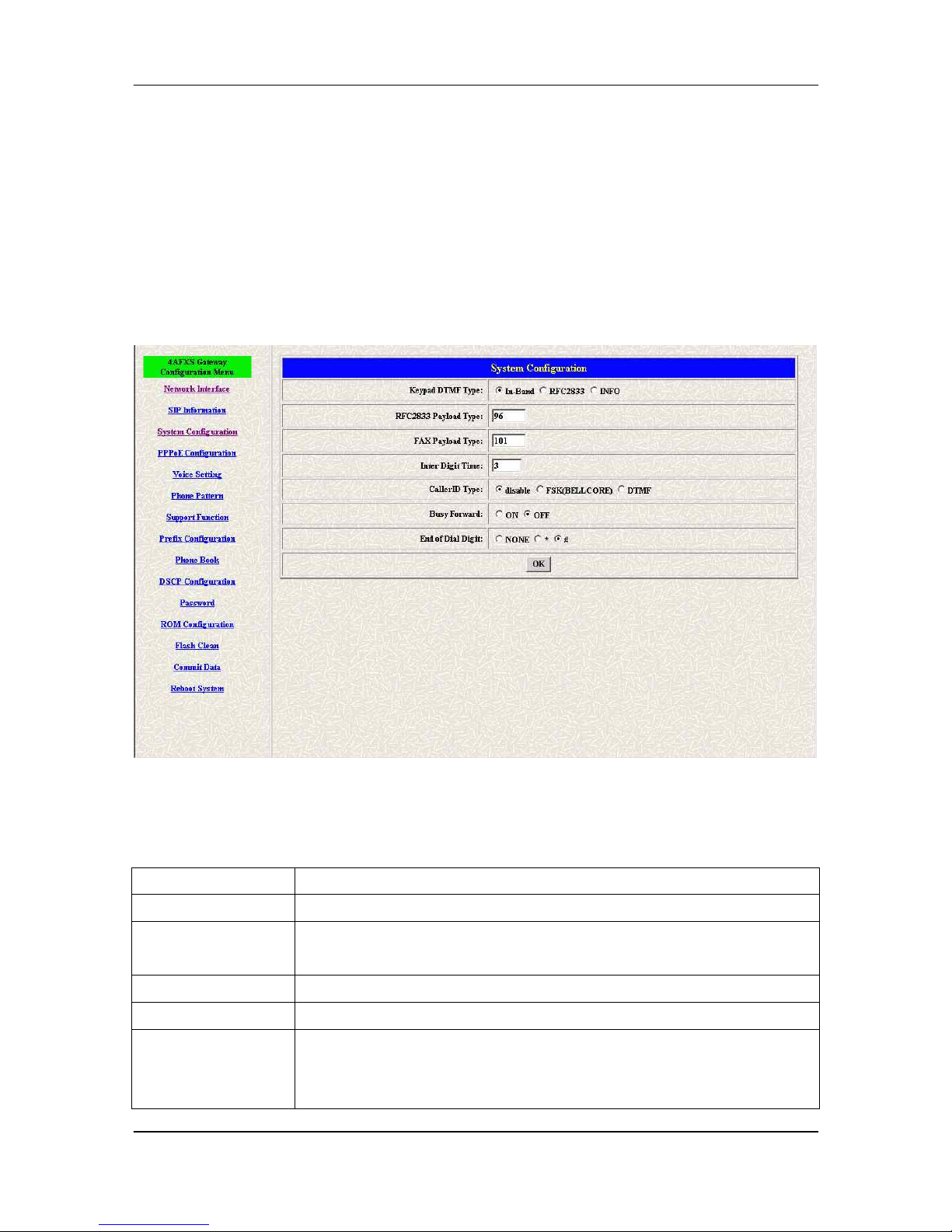
Click [System Configuration] in the navigation panel and open the [System
Configuration] Screen.
Figure 8-1 System Configuration
The following table describes this screen.
Table 8-1 System Configuration
LABEL DESCRIPTION
Keypad Type Select In-Band, RFC2833 or SIP info on DTMF replay type
RFC2833 Payload
Type
RFC2833 Payload Type (range: 96~128 inter-used:100,102~105)
FAX Payload Type Set Fax Payload Type (range: 96 or 101, default: 101)
Inter Digit Time Set the DTMF inter digit time (second)
CallerID Type Set CallerID Type (Disable, FSK, DTMF).
Support
Bell Core and DTMF callerID function. After the first ring at
destination site, device will send line number as callerID to called
Page 49

FXS Gateway Overview
- 38 -
LABEL DESCRIPTION
site.
Busy Forward
Set enable or disable to route the call to the next line (While the line
number is not matched or engaged).
End of Dial Digit Set end of dial key as NONE, *, or #.
OK [button] Click [OK] butt
on to save your changes back to the FXS Gateway
volatile memory.
Page 50
FXS Gateway Overview
- 39 -
Chapter 9
PPPoE Configuration Screen
Click [PPPoE Configuration] in the navigation panel and open the [PPPoE
Configuration] Screen.
9.1 System Configuration Overview
The web configuration provides PPPoE Configuration screen.
9.2 PPPoE Configuration Screen
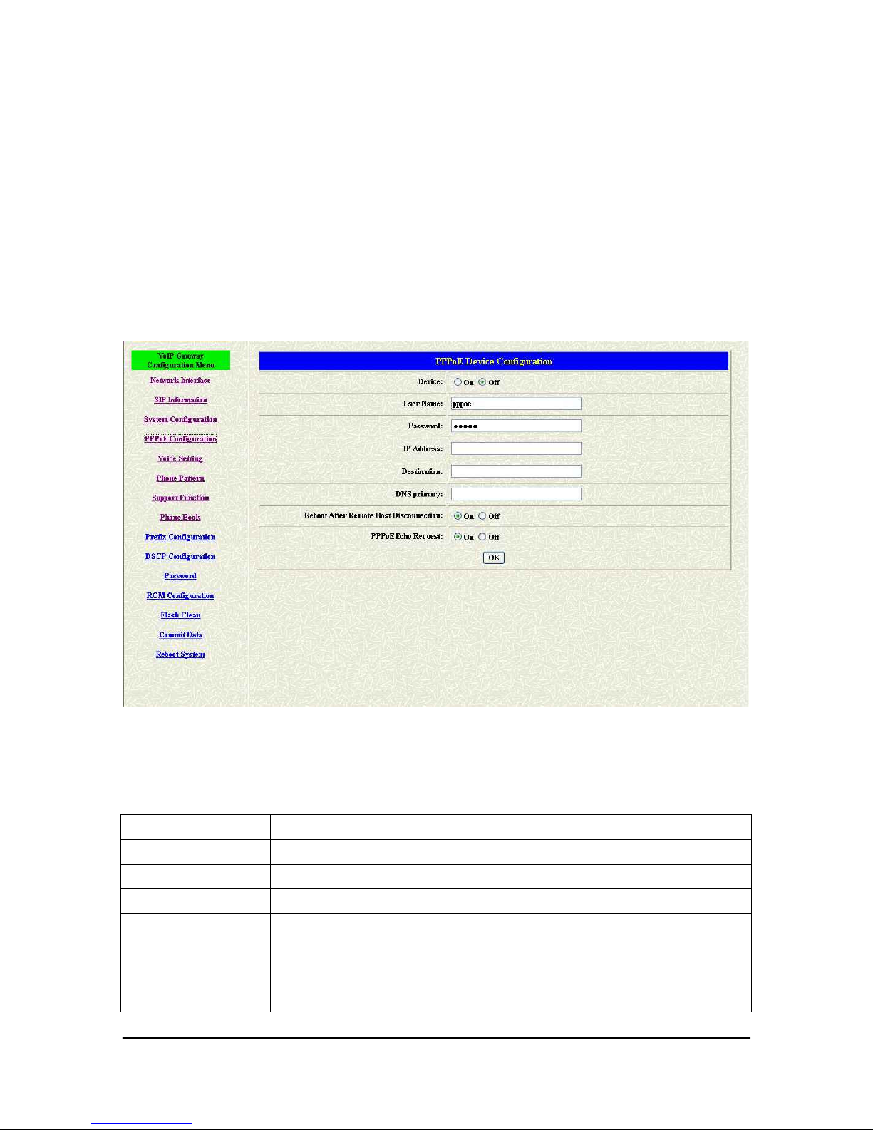
Click [PPPoE Configuration] in the navigation panel and open the [PPPoE
Configuration] Screen.
Figure 9-1 PPPoE Configuration
The following table describes this screen.
Table 9-1 PPPoE Configuration
LABEL DESCRIPTION
Device Set PPPoe function to be On or Off.
User Name Set PPPoE authentication User Name.
Password: Set PPPoE authentication password.
Reboot After
Remote Host
Disconnection
Enable/Disable auto reboot after PPPoE disconnection
PPPoE Echo Enable or Disable PPPoE echo request function
Page 51

FXS Gateway Overview
- 40 -
LABEL DESCRIPTION
Request
Other items For reference only, cannot allow to be configured.
Page 52
FXS Gateway Overview
- 41 -
Chapter 10
Voice Configuration Screen
This Chapter covers voice is associated with the audio setting information.
10.1 Voice Configuration Overview
The web configuration provides Voice Configuration screen.
10.2 Voice Configuration Screen
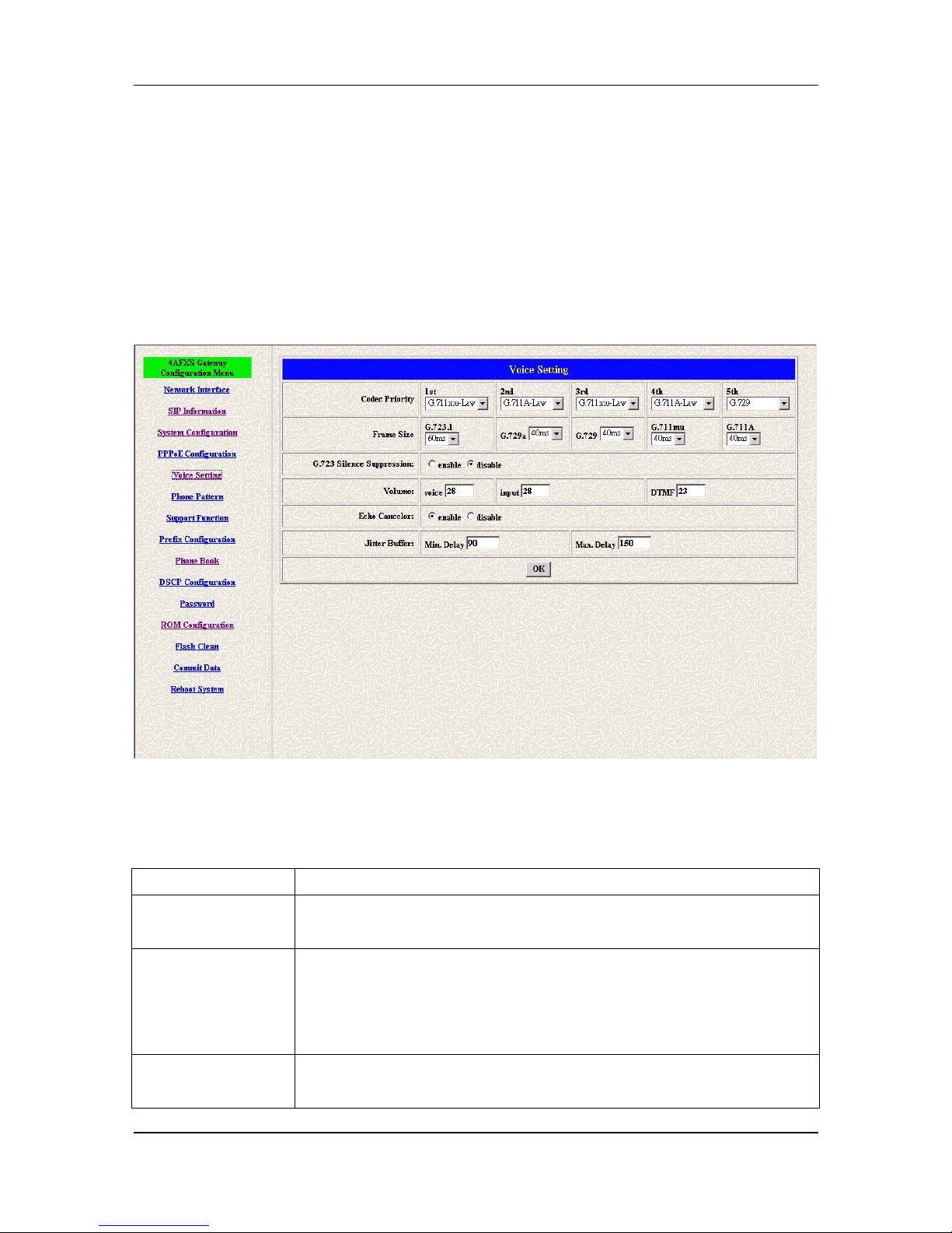
Click [Voice Configuration] in the navigation panel and open the [Voice
Configuration] Screen.
Figure 10-1 Voice Configuration
The following table describes this screen.
Table 10-1 Voice Configuration
LABEL DESCRIPTION
Codec Priority Set priority preference of installed codes, G.723, G.711A, G.711U
and G.729.
Frame Size
Set Specify sending packet size, G.723: 30/60 ms, G.711A and
G.711U: 20/40/60 ms, G.729 and G.729a: 20/40/60/80 ms.
The smaller packet size, the shorter delay time. If network is in
good condition, smaller sending packet size is recommanded.
G723 Silence
Suppression
Select enable/disable for G723 Silence Suppression function.
Page 53

FXS Gateway Overview
- 42 -
LABEL DESCRIPTION
Volume
Set voice volume stands for volume, which can be heard from FXS
Gateway side (0~63, default: 28).
Set input gain stands for volume, which the opposite party hears
(0~38, default: 28).
Set dtmf volume stands for DTMF volume/level (0~31, default: 23).
Echo Canceller Setting enable/disable of echo canceller.
Jitter Buffer Setting of jitter buffer min/max delay.
OK [button]
Click [OK] button to save your changes back to the FXS Gateway
volatile memory.
Note:
Be careful to change the voice parameters, because this might cause
incompatibility.
Page 54
FXS Gateway Overview
- 43 -
Chapter 11
Phone Configuration Screen
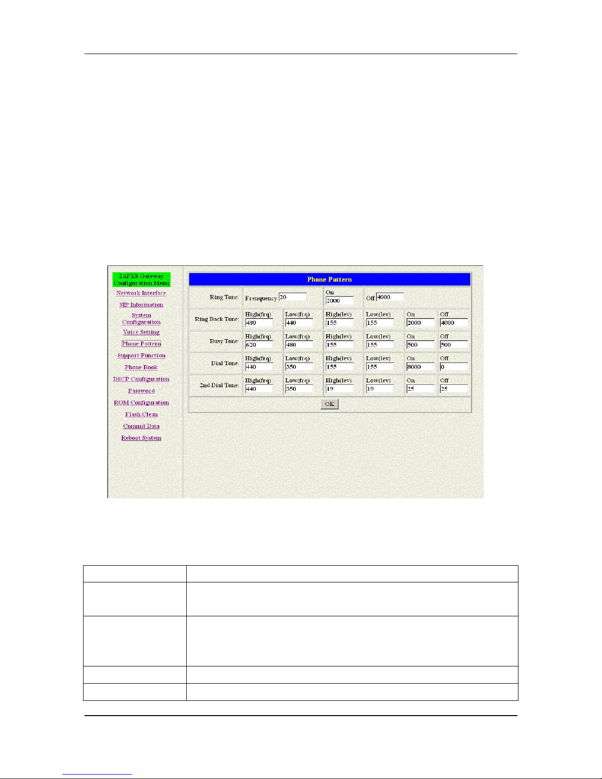
This Chapter covers FXS Gateway progress tone is configurable.
Default tone value is set according to U.S. tone specification. Users may adjust the
values according to their own country’s tone specification or users-defined tone
specification.
11.1 Phone Configuration Overview
The Web Management Interface provides [Phone Configuration] screen.
11.2 Phone Configuration Screen
Click [Phone Configuration] in the navigation panel and open the [Phone
Configuration] Screen.
Figure 11-1 Phone Pattern
The following table describes this screen.
Table 11-1 Phone Configuration
LABEL DESCRIPTION
Ring Tone Setting the played tone type, when FXS Gateway is receiving a
call.
Ring Back Tone
Setting the played tone type, when FXS Gateway receives a Q.931
Alerting message. In condition that FXS Gateway is the originate
side.
Busy Tone Setting the played tone type, when destination is busy.
Dial Tone Setting the played tone type, when hook off a phone set of
Page 55

FXS Gateway Overview
- 44 -
LABEL DESCRIPTION
workable FXS Gateway.
2nd Dial Tone To configure the value of the local 2nd dial tone.
OK [button]
Click [OK] button to save your changes back to the FXS Gateway
volatile memory.
Note:
For tone simulation, FXS Gateway adopts dual frequencies as traditional
telephone does. If users want to have their own call progress tone, they can change
the value of tones. High and Low frequency/level/cadence can be configured
respectively.
ringing frequency: 15 ~ 100 (Unit: Hz)
ringing ring ON/OFF: 0 ~ 8000 (Unit: ms)
ringing level: 0 ~ 94 (Unit: V)
tone frequency: 0 ~ 65535 (Unit: Hz)
tone freqLevel: 0 ~ 65535 (Unit: mVrms)
tone Tone ON/OFF: 0 ~ 8000 (Unit: ms)
Page 56
FXS Gateway Overview
- 45 -
Chapter 12
Support Configuration Screen
This Chapter provides some extra functions that might be needed by users.
12.1 Support Configuration Overview
The web configuration provides Support Configuration screen.
12.2 Support Configuration Screen
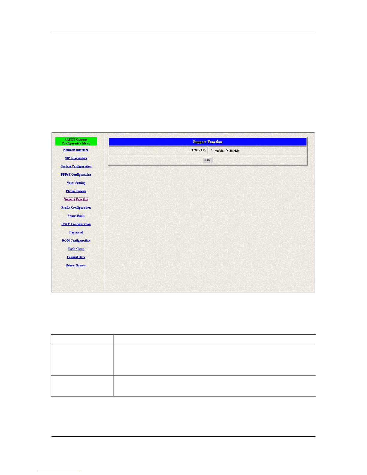
Click [Support configuration] in the navigation panel and open the [Support
Configuration] Screen.
Figure 12-1 Support Configuration
The following table describes this screen.
Table 12-1 Support Configuration
LABEL DESCRIPTION
T.38 FAX Select enable/disable for T.38 FAX fun
ction. When T.38 ability is on,
FXS Gateway will automatically defer codec (G.723 or G.729a) to
T.38 when FAX signal is detected.
OK [button]
Click [OK] button to save your changes back to the FXS Gateway
volatile memory.
Page 57
FXS Gateway Overview
- 46 -
Chapter 13
Prefix Configuration Screen
This Chapter provides some extra functions that might be needed by users.
13.1 Prefix Configuration Overview
The web configuration provides Prefix Configuration screen.
13.2 Prefix Configuration Screen
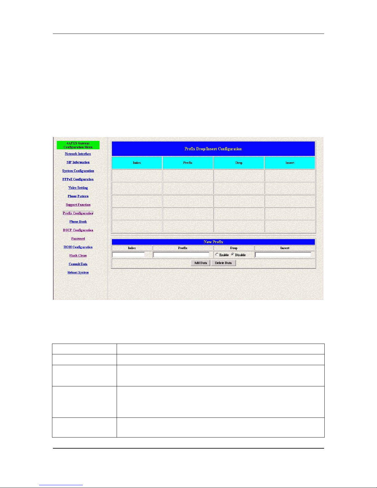
Click [Prefix configuration] in the navigation panel and open the [Prefix
Drop/Insert Configuration] Screen.
Figure 13-1 Prefix Configuration
The following table describes this screen.
Table 13-1 Prefix Configuration
LABEL DESCRIPTION
Index
Setting the index number for prefix record (max 30 record).
Prefix
Setting the prefix number of the whole numbers that could
be into this VoIP gateway (1~20 digits).
Drop Select enable or disable drop prefix function. The function is
enabled means to drop prefix number when dialing out. The
function is disabled means to keep prefix number.
Insert Setting the digits that you want to insert in this number
Page 58

FXS Gateway Overview
- 47 -
LABEL DESCRIPTION
(1~30 digits)
OK [button] Click [OK] button to save your changes back to the
FXS Gateway
volatile memory.
Page 59
FXS Gateway Overview
- 48 -
Chapter 14
Phone Book Configuration Screen
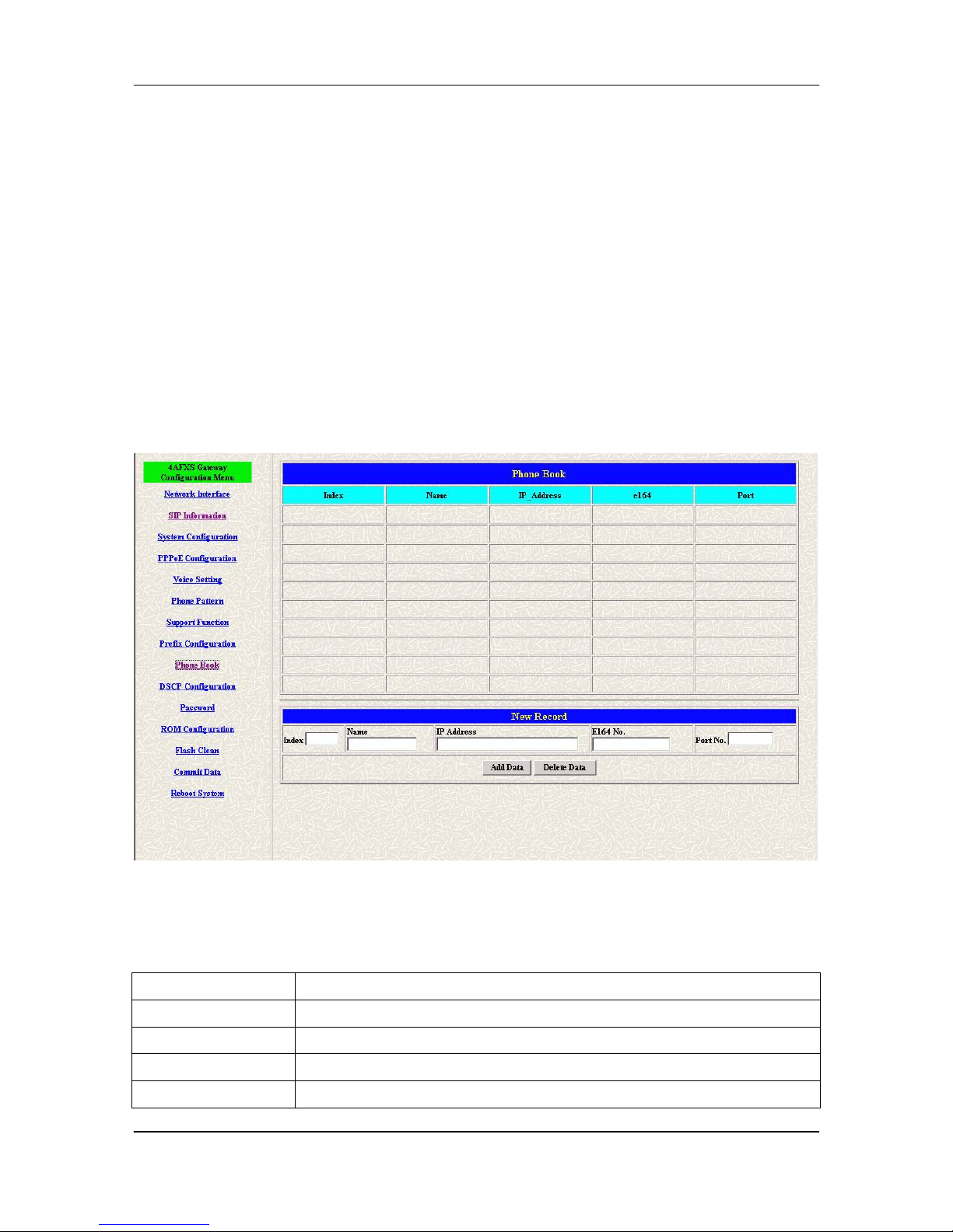
This Chapter covers Phone Book function allows users to define their own numbers,
which mapping to real IP address. It is effective only in peer-to-peer mode. When
adding a record to Phone Book, users do not have to reboot the machine, and the
record will be effective immediately.
14.1 Phone Book Configuration Overview
The web configuration allows you to Set up Phone Book that tell the FXS
Gateway how to call management traffic when you configuration P2P mode.
14.2 Phone Book Configuration Screen
Click [Phone Book Configuration] in the navigation panel and open the [Phone
Book] Screen.
Figure 14-1 Phone Book
The following table describes this screen.
Table 14-1 Phone Book
LABEL DESCRIPTION
Index The field displays the index number.
Name The field displays the descriptive name.
IP Address The field displays the IP Address or Domain name.
E164 The field displays the descriptive E164 number.
Page 60

FXS Gateway Overview
- 49 -
LABEL DESCRIPTION
Port No. The field displays the Call signal port number of caller
New Record
Index Set up an Index number
from 1 to 100, to the parameter to show
specific phone number.
Name Set up a descriptive name (max 20 byte).
IP Address Set up IP Address or Domain Name.
E164 Set up e164 (telephone) number (max 20 digits)
Port No. Call signal port number of caller
Add Data [button] Click [Add Data] button to insert the information table.
OK [button] Click [OK] button to
save your changes back to the FXS Gateway
volatile memory.
Note:
The e164 number defined in phone book will fully carry to destination. It is not just
a representative number for destination’s IP Address. In other words, user dial this
e164 number to reach destination, destination will receive the number and find out if it
is matched to its e164, including Line number in some particular device.
Page 61
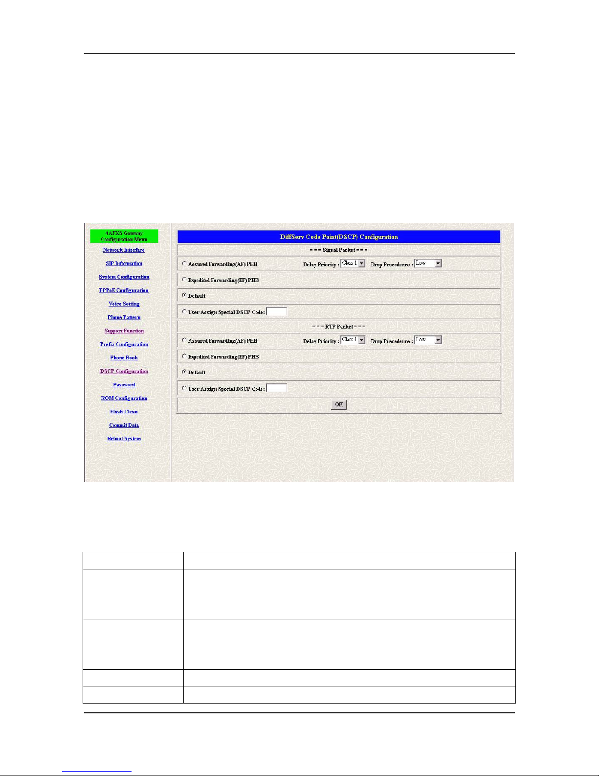
FXS Gateway Overview
- 50 -
Chapter 15
DSCP Configuration Screen
IP Packet ToS(type of Service)/Differentiated Service configuration.
15.1 DSCP Configuration
The web configurator provides DSCP Configuration screen.
15.2 DSCP Configuration Screen
Click DSCP Configuration in the navigation panel and open the DSCP
Configuration Screen.
Figure 15-1 DSCP Configuration
The following table describes this screen.
Table 15-1 DSCP Configuration
LABEL DESCRIPTION
Assured
Forwarding (AF)
PHB
Select Delay priority and Drop Precedence.
Expedited
Forwarding (EF)
PHB
Select TOS value as EF.
Default Select TOS value as 0.
User Assign Special
User can set other unspecified value here.
Page 62

FXS Gateway Overview
- 51 -
LABEL DESCRIPTION
DSCP Code
OK [button]
Click [OK] button to save your changes back to the FXS Gateway
volatile memory.
Page 63
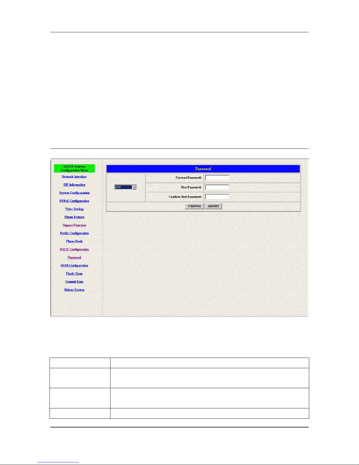
FXS Gateway Overview
- 52 -
Chapter 16
Password Configuration Screen
This Chapter explains how to change the FXS Gateway password.
16.1 Password Configuration Overview
The Password screen allows you to configure the administrator password.
16.2 Password Configuration Screen
Click [Password configuration] in the navigation panel to open the [Password
Configuration] screen.
Using the [Password Configuration] to set root and administrator password for the
FXS Gateway.
It is highly recommanded that you change the default password ([Null]].
Figure 16-1 Password Configuration
The following table describes this screen.
Table 16-1 Password Configuration
LABEL DESCRIPTION
Username Select root or administrator different options from the drop-
down list
box.
Current Password
Type the existing system password ([Null] is the default password
when shipped).
New Password Type your new system password.
Page 64

FXS Gateway Overview
- 53 -
LABEL DESCRIPTION
Confirm New
Password
Confirm your new system password for confirmation.
CHANGE [button] Click [CHANGE] to
save your change back to the FXS Gateway
volatile memory.
ABORT [button] Click [ABORT] to clean type data this page afresh.
Page 65
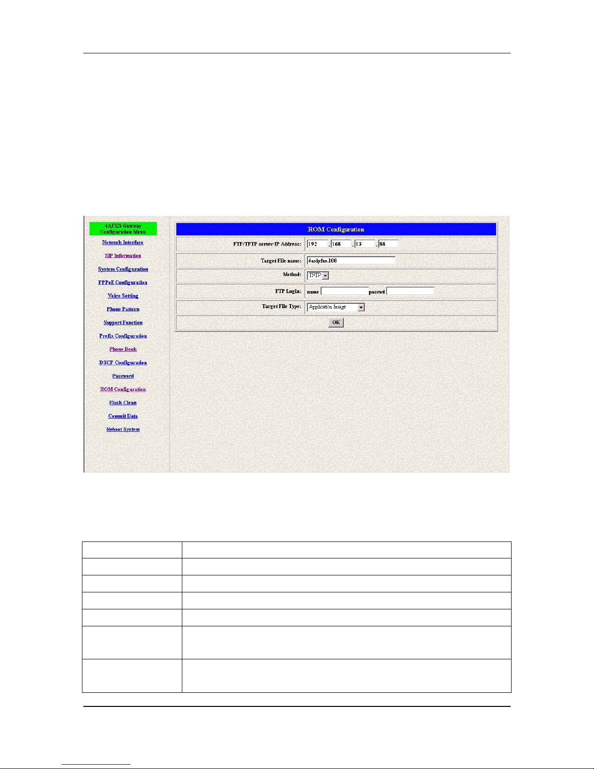
FXS Gateway Overview
- 54 -
Chapter 17
ROM Upgrade Screen
This Chapter explains how to Update FXS Gateway Version.
17.1 ROM Configuration Overview
The web configuration provides Update FXS Gateway ROM Version.
17.2 ROM Configuration Screen
Click [ROM Upgrade] in the navigation panel and open the [ROM Configuration]
Screen.
Figure 17-1 ROM Configuration
The following table describes this screen.
Table 17-1 ROM Configuration
LABEL DESCRIPTION
Server IP Address Enter the FTP or TFTP Server IP Address.
Target File Name Enter the file name prepared to upgrade.
Method Select download method as FTP or TFTP.
FTP Login Name Enter the FTP Login name (max 14 byte)
FTP Login
Password
Enter the FTP Login password (max 14 byte)
Target File Type
Select download Target File Type on 2M Boot Image, DSP
Application Image, DSP Core Image, DSP T
est Image different
Page 66

FXS Gateway Overview
- 55 -
LABEL DESCRIPTION
options from the drop-down list box.
OK [button]
Click [OK] button to save your changes back to the FXS Gateway
volatile memory.
Note:
Most of all, the Rom file needed to get upgrade is App or Boot2m. Please check
the exactly Rom file before doing download procedure.
Page 67
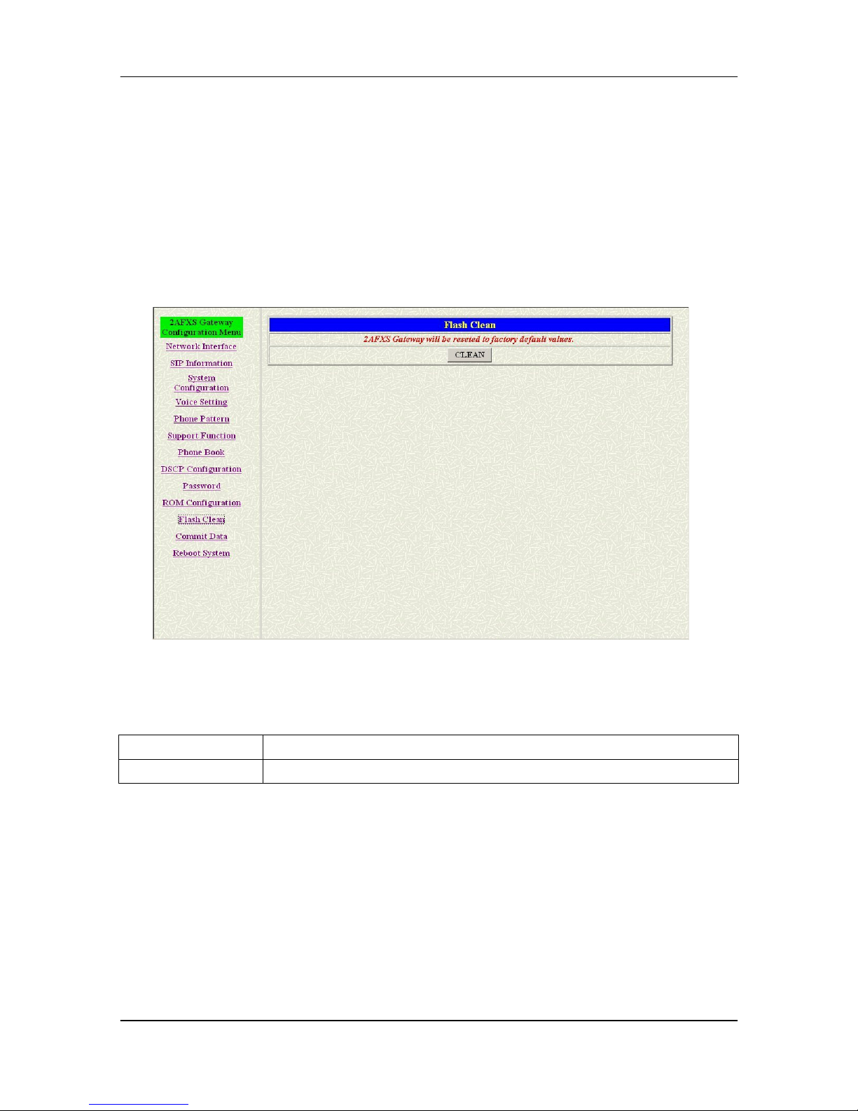
FXS Gateway Overview
- 56 -
Chapter 18
Flash Clean Screen
This Chapter covers save change and clean the entire user defined value in factory
default mode.
18.1 Flash Clean Overview
The web configuration provides Flash Clean screen.
18.2 Flash Clean Screen
Click [Flash Clean] in the navigation panel and open the [Flash Clean] Screen.
Figure 18-1 Flash Clean
The following table describes this screen.
Table 18-1 Flash Clean
LABEL DESCRIPTION
Clean [button] Clean all configuring FXS Gateway stored.
Note:
User whose login name is root only executes it. All configurations in [Network Interface]
will be kept.
Page 68
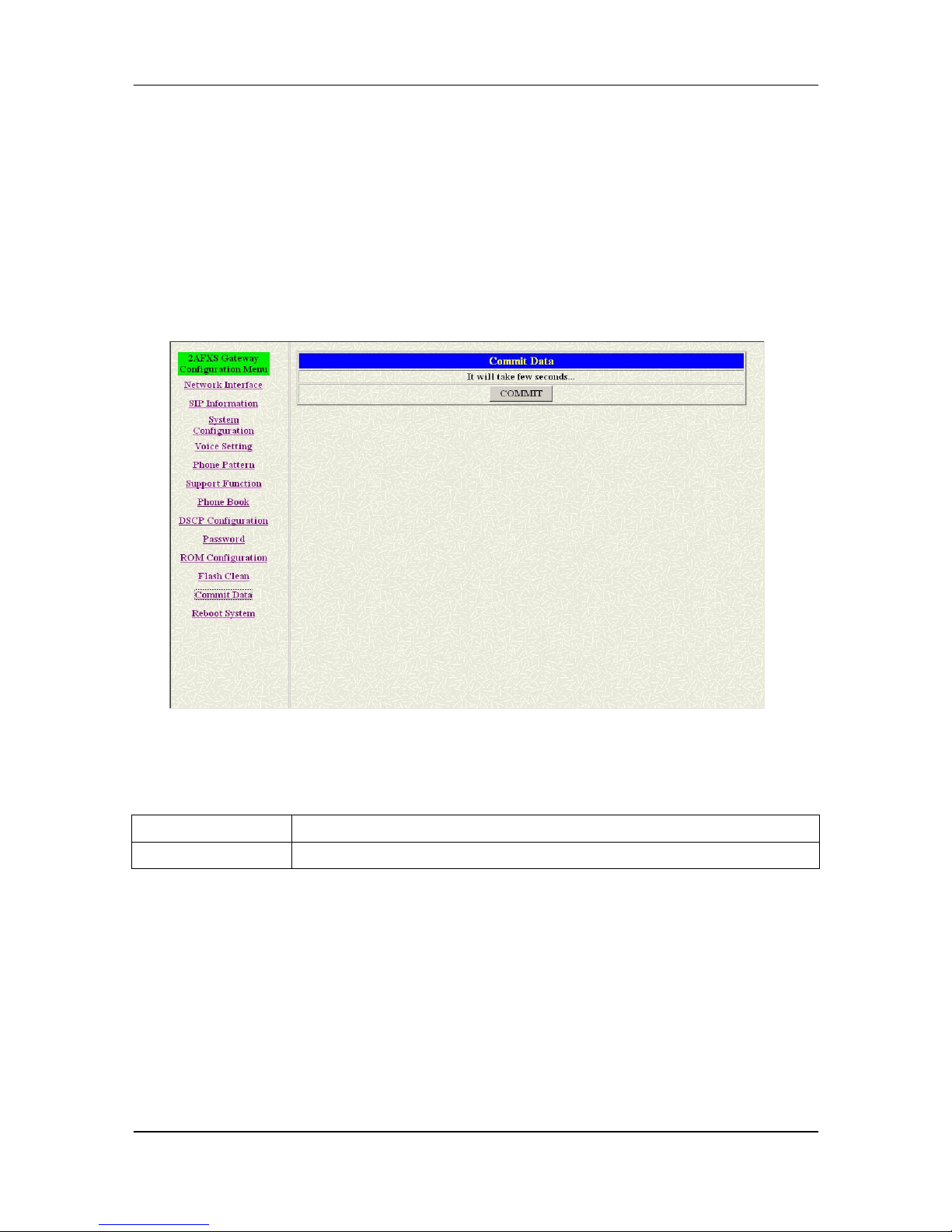
FXS Gateway Overview
- 57 -
Chapter 19
Commit Data Screen
This Chapter covers save change after configuring FXS Gateway.
19.1 Commit Configuration Data Overview
The web configuration provides Commit Configuration Data screen.
19.2 Commit Configuration Data Screen
Click [Commit Data] in the navigation panel and open the [Commit Configuration
Data] Screen.
Figure 19-1 Commit Data
The following table describes this screen.
Table 19-1 Commit Configuration Data
LABEL DESCRIPTION
Commit [button] Save changes after configuring FXS Gateway.
Page 69
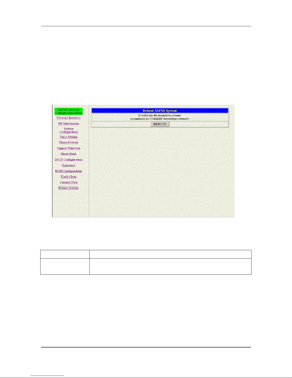
FXS Gateway Overview
- 58 -
Chapter 20
Reboot System Screen
This Chapter covers reboot to reload FXS Gateway in new configuration.
20.1 Reboot FXS Gateway Overview
The web configuration provides Reboot FXS Gateway screen.
20.2 Reboot FXS System screen
Click [Reboot System] in the navigation panel and open the [Reboot FXS
Gateway] Screen.
Figure 20-1 Reboot FXS System
The following table describes this screen.
Table 20-1 Reboot FXS System
LABEL DESCRIPTION
Reboot [button]
After commit command, type reboot to reload FXS Gateway in new
configuration. The procedure is as below:
Page 70

FXS Gateway Overview
- 59 -
Part III:
Command with FXS Gateway
This part gives information on commands to use.
Page 71
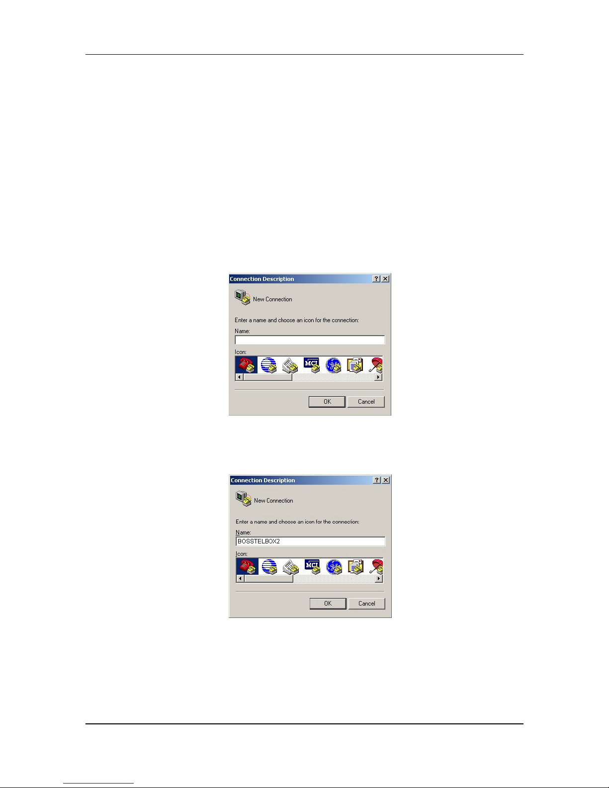
FXS Gateway Overview
- 60 -
Chapter 21
Command List
This section introduces the command line interface and lists all of the command
s.
21.1 Hyper Terminal Setting
A terminal emulator is needed when using RS-232 port to configure Gateway.
There are kinds of terminal emulator software. Here, we use Microsoft HyperTerminal
to depict how to set up terminal emulator:
Step 1. Execute the Hyper Terminal program, and then the following windows will
pop-up on the screen (STARTProgram filesAccessories Communication
Hyper Terminal).
Figure 21-1 Connection Description
Step 2. Define a name such as [3502] for this new connection, after pressing [OK]
button.
Figure 21-2 Connection Description
Step 3. The next windows appear, and then choose COM1/2 Port, which you are
going to use.
Page 72
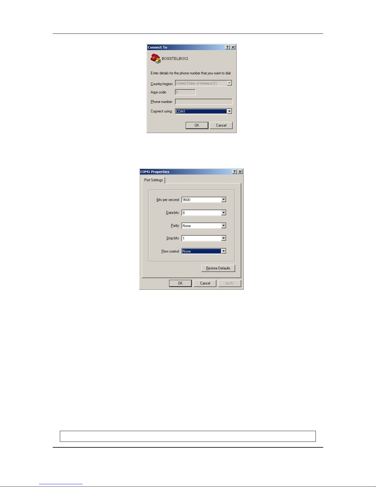
FXS Gateway Overview
- 61 -
Figure 21-3 Connect To
Step 4. Configure the COM Port Properties as following: Bits per second: 9600, Flow
control: None, Press [OK] button, and then start to configure Gateway.
Figure 21-4 Com Properties
21.2 Power On Your Gateway
At this point, you should have connected the console port, the LAN Port, the WAN
port and the power port to the appropriate devices or lines. Plug the power adapter into
a wall outlet. The Power LED should be on. The [Status LED] will come on after the
system tests are complete. The WAN LED and one of the LAN LED come on
immediately after the [Status LED] come on, if connections have been made to the
LAN and WAN ports.
Initial Screen
When you power on your Gateway it performs server internal tests as well as line
initialization.
After the tests, the Gateway asks you to enter the Login, as shown.
Attached TCP/IP interface to cpm unit 0
Page 73

FXS Gateway Overview
- 62 -
Attaching interface lo0...done
HTTPD initialized...
Flash Check
WorkMode : PROXY_MODE
Start registering to Proxy server
AC4804[0] is ok
AC4804[1] is ok
successful 2 2
Initialize OSS libraries...OK!
VP v1.42 stack open sucessfully.
login:
Figure 21-5 Initial Screen
Entering Login
For you first login, enter the login [root] and default password [Null]. As you type
the password, the screen displays and (*) for each character you type.
Attached TCP/IP interface to cpm unit 0
Attaching interface lo0...done
HTTPD initialized...
Flash Check
WorkMode : PROXY_MODE
Start registering to Proxy server
AC4804[0] is ok
AC4804[1] is ok
successful 2 2
Initialize OSS libraries...OK!
VP v1.42 stack open sucessfully.
login: root
Welcome to Terminal Configuration Mode
Please enter your configuration item
usr/config$
Page 74
FXS Gateway Overview
- 63 -
Figure 21-6 Login Screen
Note:
Login account [root] or [administrator] is the default login account and there is no
password needed.
Set Password
To set your own password in root login name, just input command [passwd –set
root ****]. For example, if password of root account is prepared as [voip], configuration
it. When set password ok, you can see ok message.
usr/config$ passwd -set root voip
Setting
Login: root
Password: voip
OK
usr/config$
Figure 21-7 Change password Screen
21.3 Command Structure with Gateway
21.3.1 Setup IP Address
Use command [ifaddr] to configure Gateway IP Address and related information.
For example:
Step 1. Setting IP address
usr/config$ ifaddr –ip 192.168.1.11 –mask 255.2555.255.0 –gate 192.168.1.254
Description:
This is to configure Gateway IP Address as [192.168.1.11], subnet mask as
[255.255.255.0], default router gateway as [192.168.1.254].
Step 2. Ather the configuration [commit] and [reboot] the device.
usr/config$ commit
usr/config$ reboot
Note:
After configured the IP Address and input the [commit], then [reboot] process,
user can start to do other configurations via HTTPD.
Page 75

FXS Gateway Overview
- 64 -
21.3.2 Application Mode Configuration
It is including Basic mode, such as Gatekeeper and Peer-to-Peer, and Advanced
mode, such as Hotline mode and IP-Sharing mode. It will be detailed in the next
Chapter.
21.3.3 Saving Your Configuration
Save the change of configurations for Gateway and apply the new configurations
by rebooting the device.
Step 1. Confirm the changed configurations, input [commit] and press [enter] key to
save it.
Step 2. Input [reboot] then press [enter] key to restart Gateway.
Step 3. After around 40 seconds, Gateway will take effect in new configurations.
These commands save all system configuration into nonvolatile memory.
Nonvolatile memory refers to the Gateway storage that remains even if the Gateway
power is turned of. Run Time (memory) is lost when the Gateway power is turned off.
You must use the command to save any configuration that you make, otherwise the
Gateway will return to its default setting when it is restarted.
Do not turn off your Gateway or remove the Gateway
while saving your configuration.
21.4 Application modes
This Chapter will introduce the four application modes users often use.
Particularly the Proxy/Gateway and Peer-to-Peer mode are the basic application mode.
User would like to set as advanced application mode, such as PPPoE Mode and
Behind IP-Sharing mode, please refer to the basic application mode for more
information.
21.4.1 Proxy mode
Proxy mode means that there will be an intermediate Proxy Server between FXS
Gateway and the remote entity. While operating at this mode, FXS Gateway will first
register to the Proxy Server located at the ISP side. For the following operation, it
sends the INVITE message to the Proxy Server once you initiate a session. Then the
Proxy server will forward the INVITE message to the right place. And the Response
message from the remote entity will be forwarded back to you via Proxy server.
Step 1. If you have one or more accounts included user name and password, you
need to configure the accounts using “security” command. For detail, please refer
to Chapter 19.7.13 [security] command.
An example is demonstrated below:
usr/config$ security –line 1 –name 12345 –password 12345
Note:
Page 76

FXS Gateway Overview
- 65 -
This is to set username (userid) as “12345”, password as “12345” into line1,
which means line1 can accept incoming calls after successfully registered to
Proxy server. If you have another account and set into line2 as shown below.
usr/config$ security –line 2 –name 54321 –password 54321
Note:
This is to set username (user id) as “54321”, password as “54321” into line2.
Then, both lines can accept incoming calls after registration.
Step 2. You must specify Proxy address obtained from your service provider. And the
Proxy address can be IPv4 address as well as DNS name. For detail, please
refer to Chapter 19.7.12 [sip] command.
Several important SIP parameters are listed below when setting proxy
mode:“–px”, ”–line1” and ”–line2”.
An example is demonstrated below:
usr/config$ sip –px 210.68.222.33 -line1 0506 –line2 0507
Note:
1. This is to set proxy address as “210.68.222.23”, line1 number as “0506”,
line2 number as “0507”
2. The line number of line1 and line2 depends on what you get from your
service provider.
Step 3. Ather the configuration [commit] and [reboot] the device.
usr/config$ commit
usr/config$ reboot
Step 4. Wait for FXS Gateway initializing in Proxy mode. It should take around 40
seconds. And you will see the below information displayed on Hyper-Terminal if
the registration is successful.
usr/config$
.
Rebooting...It will take 40 seconds....Attached TCP/IP interface to cpm
unit 0
Attaching interface lo0...done
WorkMode : PROXY_MODE
Start registering to Proxy server
HTTPD initialized...
AC4804[0] is ok
AC4804[1] is ok
successful 2 2
Initialize OSS libraries...OK!
Page 77
FXS Gateway Overview
- 66 -
VP v1.42 stack open sucessfully.
login:
21.4.2 Gateway mode
Gateway mode means that all channels use only one account to register proxy
server, but proxy must provide this function.
Step 1. If you have one accounts included user name and password, you need to
configure the accounts using “security” command.
An example is demonstrated below:
usr/config$ security –line 1 –name 12345 –password 12345
Note:
This is to set username (userid) as “12345”, password as “12345” into line1,
which means line1 can accept incoming calls after successfully registered to
Proxy server.
Step 2. You must specify Proxy address obtained from your service provider. And the
Proxy address can be IPv4 address as well as DNS name.
Several important SIP parameters are listed below when setting proxy
mode:“–px”, ”–line1” and ”–line2”.
An example is demonstrated below:
usr/config$ sip –mode 2
usr/config$ sip –px 210.68.222.33 -line1 0506 –line2 0507
Note:
1. This is to set proxy address as “210.68.222.23”, line1 number as “0506”,
line2 number as “0507”
2. The line number of line1 and line2 depends on what you get from your
service provider.
Step 3. Ather the configuration [commit] and [reboot] the device.
usr/config$ commit
usr/config$ reboot
Step 4. Wait for FXS Gateway initializing in Proxy mode. It should take around 40
seconds. And you will see the below information displayed on Hyper-Terminal if
the registration is successful.
usr/config$
. Rebooting...It will take 40 seconds....Attached TCP/IP interface to cpm
unit 0
Attaching interface lo0...done
WorkMode : PROXY_MODE
Page 78

FXS Gateway Overview
- 67 -
Start registering to Proxy server
HTTPD initialized...
AC4804[0] is ok
AC4804[1] is ok
successful 2 2
Initialize OSS libraries...OK!
VP v1.42 stack open sucessfully.
login:
21.4.3 Peer-to-Peer Mode
Peer-to-Peer Mode allows users to call other VoIP devices without the proxy
server. When in Peer-To-Peer mode, FXS Gateway use Phone Book, which will dial
predefined phone number, and press “#” (optional, to accelerate the dial) as end of
dial.
To configure Peer-To-Peer Mode in FXS Gateway, follow the steps below:
To configure Peer-To-Peer Mode in Gateway, follow the steps below:
Step 1. Set Peer-To-Peer Mode, using “sip” command
usr/config$ sip –mode 0
Note:
mode 0 is for Peer-To-Peer mode, while mode 1 is for Proxy mode.
Step 2. Configure Phone Book, using “pbook” command.
Users can refer to chapter 19.7.9 [pbook] command for more information.
usr/config$ pbook –add name TEST1 ip 10.1.1.1 e164 10
Note:
The command is to add a record onto PhoneBook. After the command
completed, you can type “pbook –print” to see if the input record is correct.
When adding a record to Phone Book, users do not have to reboot the
machine, and the record will be effective immediately. For phonebook
configuration, please refer to Chapter 19.7.9.
21.4.4 Hotline Mode
The Hotline Mode is applied in limited two peers. User just picks up the phone set
and then hears ring back tone or dial tone depended on configurations of destination
device.
Step 1. Specify gateway service type as Hotline service.
Page 79
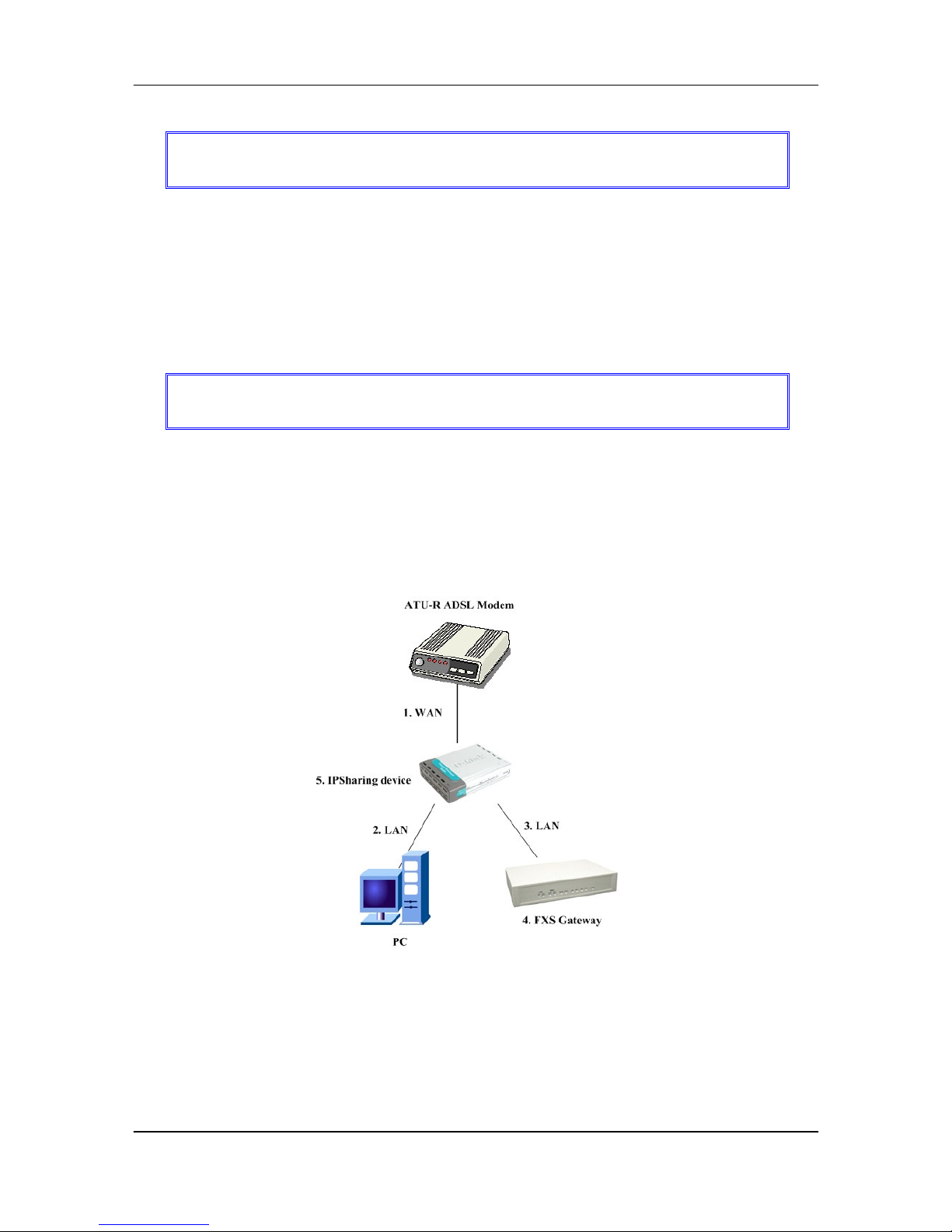
FXS Gateway Overview
- 68 -
Step 3. Create a Hotline table with [line] command.
usr/config$ sysconf –service 1
usr/config$ bureau –hotline 1 10.2.2.2 201
This example means that if user picks up phone set of FXS Line1, gateway will
automatically dial out IP address of [201].
Note:
If this gateway is under P2P mode, please set the phone book firstly.
The IP address of “bureau” command indicates the IP address of called party
in P2P mode, or the proxy IP address in proxy mode.
Step 4. After the configuration, [commit] and [reboot] the device.
usr/config$ commit
usr/config$ reboot
21.4.5 Behind IP-Sharing Mode
One Sets FXS Gateway
The function is for user whose network environment is behind IP Sharing device.
It is said Gateway is connected to the IP Sharing device.
An example such as ADSL network is in the following.
Figure 21-8 One Sets FXS Gateway
Step 1. The WAN IP Address obtained from ADSL has two kinds of methods. One is
fixed IP Address, while user applies for one or more fixed IP Addresses. Another
is dynamic IP Address while user applies for dial-up connection way.
Step 2. The LAN IP Address of User’s PC can be set as DHCP client in order to gain
a valid one.
Page 80
FXS Gateway Overview
- 69 -
Step 3. One can also assign a fixed IP address, which belongs to the same network
segment as the LAN interface of IP Sharing device.
Step 4. FXS Gateway must enable the IP Sharing function for the fixed / dynamic
WAN IP Address.
Fixed IP Address:
usr/config$ ifaddr –ipsharing 1 210.11.22.33
Dynamic IP Address:
usr/config$ ifaddr –ipsharing 1
Note:
With Dynamic WAN IP Address, when the WAN IP is changed, we need to
change the external IP of FXS Gateway using above command.
Step 5. After the configuration, [commit] and [reboot] the device.
usr/config$ commit
usr/config$ reboot
Step 6. IP Sharing device must have a function to do IP/Port mapping. Some is
named as DMZ, some is named as virtual server whatever. The VoIP messages
from WAN have to completely pass forward to the LAN. It is said if the FXS
Gateway is assigned a virtual fixed IP Address such as 192.168.1.5, IP Sharing
device must forward the VoIP message to 192.168.1.5.
Please see following for example:
>Advanced setting > NAT setting > DMZ Host setting
DMZ Host setting
▣▣▣▣ Activate DMZ
DMZ Host IP: 192.168.1.5
Page 81
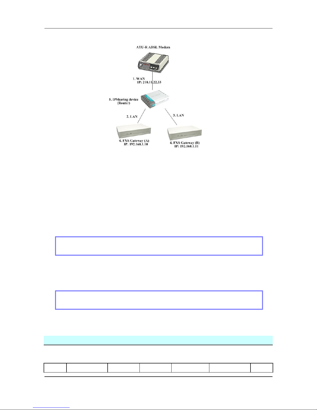
FXS Gateway Overview
- 70 -
Two Sets FXS Gateway
Figure 21-9 Two Sets FXS Gateway
Step 1. The WAN IP Address obtained from ADSL has two kinds of methods. One is
fixed IP Address, while user applies for one or more fixed IP Addresses. Another
is dynamic IP Address while user applies for dial-up connection way.
Another is dynamic IP Address while user applies for dial-up connection way.
Step 2. The LAN IP Address of User’s PC can be set as DHCP client in order to gain
a valid one.
Step 3. Assign an IP address to each set using DHCP or fixed address.
Step 4. Enable the IP Sharing function for each set using following command.
Fixed IP Address
usr/config$ ifaddr –ipsharing 1 210.11.22.33
Step 5. Configure separate SIP port and RTP port for each set to prevent from port
conflict. For example, if set A uses the default settings (SIP port: 5060, RTP port:
16384), you must change set B’s setting to SIP port equal to 5061 and RTP port
equal to 26384 for instance.
Change SIP port – usr/config$sip –port 5061
Change RTP port– usr/config$sip –rtp 26384
Step 6. Use the Port Forwarding or Port Redirection function provided by IP Sharing
device (Router). See following for example.
>Advanced setting > NAT setting > Port Redirection
Active Configuration
Items
Service name Protocol Actual Port
Virtual IP Virtual Port Enable
Page 82
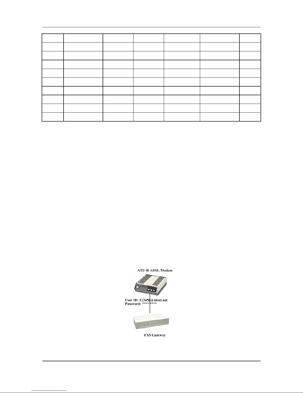
FXS Gateway Overview
- 71 -
1
1 UDP 5060 192.168.1.10
5060
V
2
2 UDP 16384 192.168.1.10
16384
V
3
3 UDP 16394 192.168.1.10
16394
V
4
4 UDP 5061 192.168.1.11
5061
V
5
5 UDP 26384 192.168.1.11
26384
V
6
6 UDP 26394 192.168.1.11
26394
V
7
--- 0 0 X
8
--- 0 0 X
9
--- 0 0 X
10
--- 0 0 X
Note:
With Dynamic WAN IP Address, when the WAN IP is changed, we need to
change the external IP of FXS Gateway using above command.
1. Different Vendor’s Router will have different appearance of setting.
2. Once you set the DMZ Host, you don’t need to configure the Port Forwarding
and vice versa.
3. If there is only one FXS Gateway attached to the IP Sharing device, it is
recommanded to use DMZ Host setting to enable the NAT traverse and
disable the Port Forwarding.
4. If there are two or more sets of FXS Gateway attached to the IP-Sharing
device, please configure the Port Redirection (Forwarding) to enable the NAT
traverse and disable the DMZ Host.
5. After the IP Sharing configuration of FXS Gateway and IP Sharing device is
complete, you must reboot the FXS Gateway to activate the new settings.
21.4.6 PPPoE Mode
Figure 21-10 PPPoE Mode
Page 83

FXS Gateway Overview
- 72 -
Step 1. Set PPPoE mode, using [pppoe]
usr/config$ pppoe –dve 1 (PPPoE used)
usr/config$ pppoe –open (PPPoE open)
Step 2. Input the user id & password provided by your ISP, using [pppoe]
usr/config$ pppoe –id [email protected] (PPPoE login account)
usr/config$ pppoe –pwd 123 (PPPoE login Passowd)
Step 3. Reboot the device once after disconnection, using [pppoe]
usr/config$ pppoe –reboot 1 (Enable)
For example:
usr/config$ pppoe -print
PPPoE adapter information
Device : Enabled
Status : Not initialized
User name : [email protected]
Password : ********
Reboot : Yes
usr/config$
Step 4. Ather the configuration [commit] and [reboot] the device.
usr/config$ commit
usr/config$ reboot
Step 5. When Gateway connection success.
For example:
usr/config$ pppoe -print
PPPoE adapter information
Device : Enabled
Status : Ready
User name : [email protected]
Password : ********
Reboot : Yes
IP address : 218.160.239.35
Destination : 61.223.128.254
DNS primary : 168.95.1.1
Page 84

FXS Gateway Overview
- 73 -
Subnet Mask : 255.255.255.255
Authenticate : PAP
Protocol : TCP/IP
Device : PPP/PPPoE
usr/config$
21.4.7 Call Hold, Transfer and Forward Mode
Gateway provides call features including call hold, transfer and forward.
Please be noted that both calling and called site have to support this feature.
For call forward function, it only works under Proxy mode. Of course, Proxy
must support these call features, too.
It is better for user to prepare a telephone set supported [FLASH]
function on keypad. If telephone set does not support [FLASH] function
on keypad, user can click the Hook quickly by sending FLASH message.
Call Hold – press [FLASH]
By pressing the FLASH after making a call, both sites will hear the 2nd dial tone
generated by Gateway. To retrieve the call back, just press the FLASH again.
Call Transfer – press [FLASH], then [transferring number]
For example, A call B, B transfer to C
A make a call to B, B press FLASH. A and B hear 2nd dial tone. B presses the C’s
number. C ringing and B hear the Ring Back tone. B can hang up this call only when C
answers the call. When B hang up the handset, A and C Make the call.
Call Forward:
Busy Forward: *77 [Forward No.] #; Cancel Busy Forward: #77#
No response/ Answer: *76 [Forward No.] #; Cancel No response/ Answer
Forward: #76#
Unconditional: *75 [Forward No.] #; Cancel Unconditional Forward: #75#
Step 1. Busy Forward: while line is engaged or phone set is off-hook.
Step 2. No response/Answer: while no one answers the call.
Step 3. Unconditional: forward it unconditionally.
21.5 How to upgrade
Before you start downloading
Step 1. Please confirm Host PC, which is installed as TFTP / FTP server and device
is in available network.
Step 2. Remember the current configuration, such as [sip], [security], [pbook], and
Page 85

FXS Gateway Overview
- 74 -
you change configuration data.
Step 3. It will list current version and default download method. Please check the
Application Rom in particular, it is showed version list, as well as the most
common one you have to upgrade.
Step 4. General speaking, App Rom is named including product name and version
and size is under 1MB, such as 4asipfxs.106. 2MB Rom is named such as
2m4asipfxs.106. Please be very careful of the prepared Rom file while
upgrading.
Step 5. Check Application Rom Version, input [rom –print] command
For example:
usr/config$ rom –print
Download Method : TFTP
Boot Rom : sdboot.200
Application Rom : 4asipfxs.106
DSP App : 48302ce3.140
DSP Kernel : 48302ck.140
DSP Test Code : 483cbit.bin
Hold Tone : holdtone.101
usr/config$
Step 6. Prepare FTP or TFTP server ready.
Upgrade steps: FTP Mode (Application Rom)
Step 1. Choose Download Method: FTP method
1. [-method]: Choose download method: FTP method,
2. input the FTP Login name and password
3. [rom -print]: check configuration data
usr/config$ rom –method 1
usr/config$ rom –ftp id password
usr/config$ rom –print
For example:
usr/config$ rom –print
Download Method : FTP
Page 86

FXS Gateway Overview
- 75 -
FTP username : test
FTP password : test
Boot Rom : sdboot.200
Application Rom : 4asipfxs.106.bin
DSP App : 48302ce3.140
DSP Kernel : 48302ck.140
DSP Test Code : 483cbit.bin
Hold Tone : holdtone.101
usr/config$
Step 2. Application Rom upgrade
1. [-app]: Choose means the prepared upgrade Rom.
2. [-s]: input the FTP Server IP Address.
3. [-f]: input the Rom files name
usr/config$ rom –app –s 192.168.1.1 –f 4asipfxs.106a
Step 3. flash –clean
Command [flash -clean] to clear old configurations. It will keep all configurations in
[ifaddr].
usr/config$ flash –clean
Upgrade steps: TFTP Mode (Boot2m)
Step 1. Choose Downlaod Method: TFTP method (default)
1. [-method]: Choose download method: TFTP method,
2. [rom -print]: check configuration data
usr/config$ rom –method 0
usr/config$ rom –print
For example:
usr/config$ rom –print
Download Method : TFTP
Boot Rom : sdboot.200
Application Rom : 4asipfxs.106
DSP App : 48302ce3.140
DSP Kernel : 48302ck.140
DSP Test Code : 483cbit.bin
Page 87
FXS Gateway Overview
- 76 -
Hold Tone : holdtone.101
usr/config$
Step 2. Boot2m upgrade
1. [-boot2m]: Choose means the prepared upgrade Rom.
2. [-s]: input the FTP Server IP Address.
3. [f]: input the Rom files name
usr/config$ rom –boot2m –s 192.168.1.1 –f 2m4asipfxs.106a
Step 3. Find out MAC Address:
There are 12 digits on label on the back panel of the device, or command as
[ifaddr -ifshow] (find the list information of Ethernet address, it is MAC Address).
usr/config$ ifaddr –ifshow
For example:
usr/config$ ifaddr -ifshow
cpm (unit number 0):
Flags: (0x8063) UP BROADCAST MULTICAST ARP RUNNING
Type: ETHERNET_CSMACD
Internet address: 192.168.13.80
Broadcast address: 192.168.15.255
Netmask 0xfffff800 Subnetmask 0xfffff800
Ethernet address is 00:01:a8:00:27:43
Metric is 0
Maximum Transfer Unit size is 1500
0 octets received
0 octets sent
221 packets received
0 packets sent
221 unicast packets received
0 unicast packets sent
0 non-unicast packets received
0 non-unicast packets sent
0 input discards
0 input unknown protocols
0 input errors
138 output errors
0 collisions; 0 dropped
Step 4. Set MAC Address:
Page 88
FXS Gateway Overview
- 77 -
usr/config$ setmac
- enter mac address (xxxxxxxxxxxx):
For example:
usr/config$ setmac
- enter mac address (xxxxxxxxxxxx):0001a8002743
- the mac address is 00 01 a8 00 27 43
- if mac address is correct,please press 'y' to
setup configuration,else press 'n' to continue
y
- mac address configuraton OK.
usr/config$
Step 5. Set IP Address:
usr/config$ ifaddr –ip xxx.xxx.xxx.xxx –mask xxx.xxx.xxx.xxx –gate
xxx.xxx.xxx.xxx
Step 6. commit, reboot
usr/config$ commit
usr/config$ reboot
21.6 Commands with FXS Gateway
The following table lists all of the commands that you can use with the Gateway.
Refer to the following chapters for descriptions of commonly used commands.
This user’s guide describes commands that are helpful for configuring the
Gateway. Using commands not documented in the user’s guide can damage the
unit and possibly render it unusable.
Table 21-1 Commands with FXS Gateway
Command DESCRIPTION
help help/man/?[command]
quit quit/exit/close.
debug Show debug message.
reboot Reboot local machine.
flash Clean configuration from flash rom.
commit Commit flash rom data.
ifaddr Internet address manipulation.
time Show current time.
ping Test that a remote host is reachable.
Page 89

FXS Gateway Overview
- 78 -
Command DESCRIPTION
pbook Phonebook information and configuration.
pppoe PPPoE stack manipulation.
sysconf System information manipulation.
Pro Pro information manipulation.
sip This command is to configure SIP related parameters.
security This command is used to configure the account information
included username and password obtained from the service
provider.
voice Voice information manipulation.
support Special Voice function support manipulation.
tos TOS service allows users to achieve QoS on IP network.
phone Setup of call progress tones and ringing (SLIC control).
bureau To set Hotline function must be under Peer-to-Peer mode and
switch to hotline mode.
rom ROM file update.
auth Set configuration items for "administrator" user.
passwd Password setting information and configuration.
line Line information manipulation
prefix Prefix drop/insert information manipulation
21.7 System Commands Overview
21.7.1 [quit]
Type [quit] will quit the Gateway configuration mode. And turn back to login
prompt.
usr/config$ quit
Disconnecting..
login: root
Welcome to Terminal Configuration Mode
Please enter your configuration item
usr/config$
Figure 21-11 quit command
Note:
It is recommanded that type the [quit] command before you leave the console. If
Page 90

FXS Gateway Overview
- 79 -
so, Gateway will ask password again when next user connects to console port.
21.7.2 [debug]
Open debug message will show up specific information while Gateway is in
operation. After executing the debug command, it should execute command
[debug –open] as well.
usr/config$ debug
Debug message information and configuration
Usage:
debug [-add type1 [[type2]...]] | -open | -close | -status
-status Display the enabled debug flags.
-add Add debug flag.
-delete Remove specified debug flag.
-open Start to show debug messages.
-close Stop showing debug messages.
Example:
debug -add sip msg
debug -open
usr/config$
Figure 21-12 debug command list
Parameter Usages:
-status: Display the enabled debug flags.
-add: Add debug flag.
-- sip: sip related information
-- msg: voice related information
-delete: Remove specified debug flag.
-open: Start to show debug messages.
-close: Stop showing debug messages.
In this example, user open debug flags including sip, vp, msg.
usr/config$ debug -add sip msg
usr/config$ debug –open
For example:
usr/config$ debug -status
Page 91

FXS Gateway Overview
- 80 -
Current debug type enabled :
Debug Mode is open
DEBUG-> SIP MSG
usr/config$
Figure 21-13 debug –status command
21.7.3 [reboot]
After [commit] command, type [reboot] to reload Gateway in new configuration.
The procedure is as below:
usr/config$ reboot
Start to Unregister ...
Unregister complete...
. Rebooting...It will take 40 seconds....Attached TCP/IP interface to cpm unit 0
Attaching interface lo0...done
HTTPD initialized...
Flash Check
WorkMode : PROXY_MODE
Start registering to Proxy server
AC4804[0] is ok
AC4804[1] is ok
successful 2 2
Initialize OSS libraries...OK!
VP v1.42 stack open sucessfully.
login:
Figure 21-14 reboot command
21.7.4 [flash]
Clean the configuration stored in flash.
usr/config$ flash
Flash memory information and configuration
Usage:
flash [-clean]
Page 92

FXS Gateway Overview
- 81 -
flash -clean Clean the configuration stored.
Note:
This command will clean the configuration stored in
the flash and reboot it.
usr/config$
Figure 21-15 flash command list
Parameter Usages:
-clean: clean all the user defined value, and reboot Gateway in factory default mode.
Note:
It is recommanded that use [flash –clean] after application firmware id upgraded.
Warning:
User whose login name is root only executes it. All configurations in command
[ifaddr] and [pppoe] will be kept.
For example:
usr/config$ flash -clean
Flash clean start
Flash clean success!!
!! rebooting ...
Attached TCP/IP interface to cpm unit 0
Attaching interface lo0...done
HTTPD initialized...
Flash Check
WorkMode : PROXY_MODE
Start registering to Proxy server
AC4804[0] is ok
AC4804[1] is ok
successful 2 2
Page 93

FXS Gateway Overview
- 82 -
Initialize OSS libraries...OK!
VP v1.42 stack open successfully.
login:
Figure 21-16 flash –clean command
21.7.5 [commit]
Save changes after configuring Gateway.
usr/config$ commit
This may take a few seconds, please wait..
Commit to flash memory ok!
usr/config$
Figure 21-17 commit command
Note:
Users shall use [commit] to save modified value, or they will not be activated after
system reboot.
21.7.6 [ifaddr]
Configure and display Gateway network information.
usr/config$ ifaddr
LAN information and configuration
Usage:
ifaddr [-print]|[-dhcp used]|[-sntp mode [server]]
ifaddr [-ip ipaddress] [-mask subnetmask] [-gate defaultgateway]
ifaddr [-dns index [dns server address]] [-ipsharing used[ip address]]
ifaddr [-autodns used]
-print Display LAN information and configuration.
-ip Specify ip address.
-mask Set Internet subnet mask.
-gate Specify default gateway ip address
-dhcp Set DHCP client service flag (On/Off).
-sntp Set SNTP server mode and specify IP address.
-autodns Specify the way to obtain DNS Server (0:Manual/1:Auto).
Page 94

FXS Gateway Overview
- 83 -
-dns specify IP address of DNS Server.
-timezone Set local timezone.
-ipsharing Specify usage of an IP sharing device and specify IP address.
-httpdport WEB management HTTP port.
-stun Specify STUN Server address(x:disable STUN).
-stunport Specify STUN Server port.
-security The encrypt switch (0:Off/1:On).
-key The encrypt key
Note:
Range of ip address setting (0.0.0.0 ~ 255.255.255.255).
DHCP client setting value (On=1, Off=0). If DHCP set to 'On',
Obtain a set of Internet configuration from DHCP server assgined.
SNTP mode (0=no update, 1=specify server IP, 2=broadcast mode).
Example:
ifaddr -ip 210.59.163.202 -mask 255.255.255.0 -gate 210.59.163.254
ifaddr -dhcp 1
ifaddr -sntp 1 210.59.163.254
ifaddr -ipsharing 1 210.59.163.254
ifaddr -autodns 1
ifaddr -dns 1 168.95.1.1
ifaddr -security 1
ifaddr -key welltech
usr/config$
Figure 21-18 ifaddr command list
Parameter Usages:
-print: Print current IP setting and status
-ip: Assigned IP address for Gateway
-mask: Assigned internet subnet mask
-gate: Assigned IP default gateway
-dhcp: Dynamic Host Configuration (1 = ON; 0 = OFF)
-dns: Setup DNS Server IP Address.
-sntp: Simple Network Time Protocol (0=No update, 1=Specify server IP, 2=broadcast
mode). When SNTP function is activated, users have to specify a SNTP
server as network time source. An example is demonstrated below:
usr/config$ ifaddr -sntp 1 10.1.1.1
Page 95

FXS Gateway Overview
- 84 -
-autodns: Auto or manual configures the DNS IP address when gateway device is
under DHCP and PPPoE mode.
-timezone: set local time zone according to GMT
-ipsharing: To specify a global fixed IP address, user can add this IP address in the
command.
usr/config$ ifaddr -ipsharing 1 210.11.22.33
Note:
If the IP address is not a fixed one, the dedicated IP address is not necessary
in the command. However, dynamic IP Address is not working in Peer-to-Peer
mode.
For example:
usr/config$ ifaddr -print
Internet address information
WAN IP address : 192.168.13.4
Subnet mask : 255.255.248.0
Default gateway : 192.168.8.254
DHCP startup : OFF
SNTP : mode=1
server 168.95.195.12
time zone : GMT+8
cycle=1024 mins
IPSharing : no IPSharing device.
Primary DNS Server : 168.95.192.1
Secondary DNS Server : 168.95.1.1
usr/config$
Figure 21-19 ifaddr –print command
21.7.7 [time]
When SNTP function of Gateway is enabled and SNTP server can be found as
well, type [time] command to show current network time.
usr/config$ time
Current time is WED SEP 17 12:36:49 2003
usr/config$
Page 96

FXS Gateway Overview
- 85 -
Figure 21-20 time command list
21.7.8 [ping]
Use [ping] to test whether a specific IP is reachable or not.
For example: if 192.168.1.2 is not existing while 210.63.15.32 exists. Users will
have the following results:
For example:
usr/config$ ping 192.168.1.2
no answer from 192.168.1.2
usr/config$ ping192.168.1.254
PING 192.168.1.254: 56 data bytes
64 bytes from 192.168.1.254: icmp_seq=0. time=5. ms
64 bytes from 192.168.1.254: icmp_seq=1. time=0. ms
64 bytes from 192.168.1.254: icmp_seq=2. time=0. ms
64 bytes from 192.168.1.254: icmp_seq=3. time=0. ms
----192.168.1.254 PING Statistics---4 packets transmitted, 4 packets received, 0% packet loss
round-trIP (ms) min/avg/max = 0/1/5
210.63.15.32 is alive
usr/config$
Figure 21-21 ping command list
21.7.9 [pbook]
Phone Book function allows users to define their own numbers, which mapping to
real IP address. It is effective only in peer-to-peer mode. When adding a record to
Phone Book, users do not have to reboot the machine, and the record will be effective
immediately.
usr/config$ pbook
Phonebook information and configuration
Usage:
pbook [-print [start_record] [end_record]]
pbook [-add [ip ipaddress] [name Alias] [e164 phonenumber]]
pbook [-search [ip ipaddress] [name Alias] [e164 phonenumber]]
pbook [-insert [index] [ip ipaddress] [name Alias] [e164 phonenumber] [port
numb
er]]
Page 97

FXS Gateway Overview
- 86 -
pbook [-delete index]
pbook [-modify [index] [ip ipaddress] [name Alias] [e164 phonenumber] [port
numb
er]]
-print Display phonebook data.
-add Add an record to phonebook.
-search Search an record in phonebook.
-delete Delete an record from phonebook.
-insert Insert an record to phonebook in specified position.
-modify Modify an exist record.
Note:
If parameter 'end_record' is omited, only record 'start_record' will be disp
lay.
If both parameters 'end_record' and 'start_record' are omited, all records
will be display.
Range of ip address setting (0.0.0.0 ~ 255.255.255.255).
Range of index setting value (1~100),
Example:
pbook -print 1 10
pbook -print 1
pbook -print
pbook -add name Test ip 210.59.163.202 e164 1001
pbook -insert 3 name Test ip 210.59.163.202 e164 1001
pbook -delete 3
pbook -search ip 192.168.4.99
pbook -modify 3 name Test ip 210.59.163.202 e164 1001
usr/config$
Figure 21-22 pbook command list
Parameter Usages:
-print: Print out current contents of Phone Book. Users can also add index number,
from 1 to 100, to the parameter to show specific phone number.
Note:
Index number: means the sequence number in phone book. If users do
request a specific index number in phone book, Gateway will give each record a
automatic sequence number as index.
Page 98

FXS Gateway Overview
- 87 -
-add: add a new record to phone book. When adding a record, users have to specify
name, IP, and e164 number to complete the command.
--name: Name to represent caller.
--e164: e.164 number for mapping with IP address of caller
--ip: IP address of caller
--port: Call signal port number of caller
--drop : Drop e.164 number when dial out. 0 means to keep e.164 number, 1
means to drop e.164 number when dialing out.
--inert: Insert digits.(1~10 digits)
usr/config$ pbook –add name test e164 100 ip 192.168.13.78
-modify: modify an existing record. When using this command, users have to specify
the record’s index number, and then make the change.
usr/config$ pbook –modify 1 name test e164 5678 ip 192.168.1.10 port 1730
drop 0
-delete: delete a specific record. [pbook –delete 3] means delete index 3 record.
usr/config$ pbook –delete 3
PhoneBook Rules:
The e164 number defined in phone book will fully carry to destination. It is not just
a representative number for destination’s IP Address. In other words, user dial this
e164 number to reach destination, destination will receive the number and find out if it
is matched to its e164, including Line number in some particular device.
For example:
usr/config$ pbook -print
index Name IP E164 Port
========================================================
1 74 192.168.13.74 74
--------------------------------------------------------
usr/config$
Figure 21-23 pbook -print command
21.7.10 [pppoe]
Display PPPoE related information.
usr/config$ pppoe
PPPoE device information and configuration
Page 99

FXS Gateway Overview
- 88 -
Usage:
pppoe [-print]|[-open]|[-close]
pppoe [-dev on/off][-id username][-pwd password]
-print Display PPPoE device information.
-dev Enable(=1) or Disable(=0) device.
-open Open PPPoE connection.
-close Disconnect PPPoE connection.
-id Connection user name.
-pwd Connection password.
-reboot Reboot after remote host disconnection.
-echo PPPoE Echo Request (0=disable, 1=enable).
usr/config$
Figure 21-24 pppoe command list
Parameter Usages:
-print: print PPPoE status.
-dev: Enable PPPoE Dial-up function
-open: Open the connection
-close: Close the connection
-id: Input the User name ID provided by ISP
-pwd: Input the User name password provided by ISP
-reboot: Reboot the PPPoE connection.
-echo: Enable or Disable PPPoE echo request function.
For example:
usr/config$ pppoe -print
PPPoE adapter information
Device : Enabled
Status : Not initialized
User name : pppoe
Password : *****
Reboot : No
Echo : Enable
usr/config$
Figure 21-25 pppoe –print command list
Page 100

FXS Gateway Overview
- 89 -
21.7.11 [sysconf]
This command displays system information and configurations.
usr/config$ sysconf
System information and configuration
Usage:
sysconf [-print] [-idtime digit] [-bf digit] [-keypad dtmf]
[-faxtype type][-2833type type][-lcdrop ON/OFF]
[-droptime digit][-eod digit] [-callerid type]
[-service used][-dtmfstart digits] [-dtmfend digits]
sysconf -print
-print Display system overall information and configuration.
-idtime Inter-Digits time.(1~10 sec)
-service Specify gateway service type. (0: Dial in service,
1: HotLine service.)
-bf BusyForward.(ON:1 / OFF:0)
-keypad Select DTMF type: 0=In-band,
1=RFC2833.
2=INFO.
-faxtype FAX Payload Type (range:96~128
inter-used:100,102~105)
-2833type RFC2833 Payload Type (range:96~128
inter-used:100,102~105)
-lcdrop Disconnect Supervision(Loop Current Drop) (ON:1 / OFF:0)
-droptime Period of Loop Current Drop (ms)
-eod End of Dial Digit setting(0: none, 1: *, 2: #)
-callerid Caller ID Type setting, 0: Disable,
1: FSK(BELLCORE),
2: DTMF.
-dtmfstart DTMF CallerID Start Symbol.
-dtmfend DTMF CallerID End Symbol.
-ivr IVR Auto Hang up (0:Disable /1:Tone /2:reverse )
-userphone Add user=phone parameter in the SIP message (ON:1/OFF:0)
-billing Billing Mode(0:None/1:Reverse/2:Tone/3:F12K/4:F16K)
-bmod Billing Method Mode(0:Only Once/1:Repeat)
-transfer Transfer Mode(0:Disable/1:Enable)
-mwi Enable the MWI subscription function
 Loading...