

Page 1

APPLICATION NOTE
User Manual of High-End
RDS/EON Car Radio System
CCR612 (V0.3)
AN96029
Page 2

Philips Semiconductors
User Manual of High-End RDS/EON
Car Radio System CCR612 (V0.3)
Abstract
The CCR612 is a computer controlled car radio system based on a P83CE528 micro controller. It controls a
high-end AM/FM car radio with RD(B)S, EON and various I2C controlled peripherals. It can be interfaced to a
SCC600 CD-changer
The system contains functions such as PLL tuning, IF control, stereo decoding, RDS/RBDS+EON decoding, IAC,
sound switching, sound fader control, LCD display, cassette interface, external audio input jack and a detachable
front. An interface to control a CD-changer is also provided.
Radio control and RDS/RBDS+EON processing are combined in a single microcontroller.
Application Note
96029
"The purchase of Philips’ complete set of Integrated Circuits as specified in this User Manual for manufacture of
a radio system conforming the relevant specification as herein given, secures immunity from suit on
unauthorized use of those Philips’ patent rights, which specifically relate to automatic broadcast station storage
(AST) and/or radio data system (RDS) features."
Purchase of Philips I2C components conveys
a license under the I2C patent to use the components in the I2C system, provided the
system conforms to the I2C specifications
defined by Philips.
© Philips Electronics N.V. 1997
All rights are reserved. Reproduction in whole or in part is prohibited without the prior written consent of the copyright owner.
The information presented in this document does not form part of any quotation or contract, is believed to be
accurate and reliable and may be changed without notice. No liability will be accepted by the publisher for any
consequence ofitsuse. Publication thereof does notconvey nor implyany license underpatent- or other industrial
or intellectual property rights.
2
Page 3

Philips Semiconductors
User Manual of High-End RDS/EON
Car Radio System CCR612 (V0.3)
APPLICATION NOTE
User Manual of High-End
RDS/EON Car Radio System
CCR612 (V0.3)
AN96029
Author(s):
A. Demmers
M. Verheijden
Product Concept & Application Laboratory Eindhoven,
The Netherlands
Application Note
96029
Keywords
Car Radio
RDS
RBDS
EON
CCR612
ICE (TEA6811 / TEA6822)
SOFAC (TEA6320, 6321, 6322 or 6323)
CD-changer
Number of pages: 94
Date: 1996-05-24
3
Page 4

Philips Semiconductors
User Manual of High-End RDS/EON
Car Radio System CCR612 (V0.3)
Summary
CCR612 is a computer controlled car radio system based on a P83CE528 microcontroller. It controls a high-end
AM/FM car radio with R(B)DS (Radio Broadcasting Data System), EON (Enhanced Other Network) and various
I2C-bus controlled peripherals.
The system contains functions such as PLL tuning, IF control, stereo decoding, RDS/RBDS+EON decoding, IAC,
sound switching, sound fader control, LCD display, cassette interface, external audio input jack and a detachable
front. An interface to control a CD-changer is also provided.
Radio control and RDS/RBDS+EON processing are combined in a single microcontroller.
Application Note
96029
4
Page 5

Philips Semiconductors
User Manual of High-End RDS/EON
Car Radio System CCR612 (V0.3)
Application Note
96029
CONTENTS
1 INTRODUCTION ............................................................... 11
1.1 Definitions, Acronyms and Abbreviations ...................................... 12
1.2 References .............................................................. 12
2 HARDWARE CONFIGURATION .................................................. 13
2.1 Block diagram CCR612 .................................................... 13
2.1.1 Main Board Part 1a (Basic AM/FM stereo Radio Part) ................... 13
2.1.2 Main Board Part 1b (Optional Power Amplifier, 2 x TDA8561Q) ........... 15
2.1.3 Main Board Part 1c (Optional Source Sel. & Audio Contr.
HEF4052B/TDA1526) ............................................. 15
2.1.4 Main Board Part 2a ( Micro-controller, EEPROM and RDS Demodulator) .... 16
2.1.5 Main Board Part 2b (Detachable Front) ............................... 16
2.1.6 Main Board Part 3 (Cassette Interface including Dolby B*) ............... 16
2.1.7 Front Panels ..................................................... 17
2.1.7.1 Front Panel Part FP-1a (Key and Display panel) .............. 17
2.1.7.2 Front Panel Part FP-1b (Detachable Front Version). .......... 17
2.1.8 Diagram ICE module. .............................................. 17
2.1.9 Diagram PACS Sub Board ......................................... 18
2.1.10 PCB LAY-OUTS of CCR612 sample Version D. ........................ 18
2.2 Performance of the radio ................................................... 19
3 SHORT SPECIFICATION ........................................................ 23
4 CCR612S PINNING AND INTERFACING ........................................... 30
4.1 Pinning overview .......................................................... 30
4.2 Factory options ........................................................... 38
4.2.1 Diode options .................................................... 38
4.2.2 Automatically detected options ...................................... 39
2
4.3 I
4.4 The keyboard ............................................................ 39
4.5 Power stabilizer interface. .................................................. 42
4.6 LCD display. ............................................................. 44
4.7 Non Volatile Memory. ...................................................... 45
5 KEY FUNCTIONS .............................................................. 46
6 FUNCTIONAL DESCRIPTION .................................................... 57
6.1 Switching on / off .......................................................... 57
6.2 Tuning .................................................................. 58
C bus addresses ......................................................... 39
4.4.1 Fixed keyboard ................................................... 40
4.4.2 Detachable keyboard .............................................. 40
4.4.3 Keyboard options ................................................. 41
6.2.1 Band switching ................................................... 58
6.2.2 Manual/search tuning ............................................. 58
6.2.3 Frequency scan .................................................. 60
5
Page 6

Philips Semiconductors
User Manual of High-End RDS/EON
Car Radio System CCR612 (V0.3)
6.2.4 Selecting preset stations ........................................... 60
6.2.5 Storing stations in preset memory .................................... 60
6.2.6 AST search ...................................................... 61
6.2.7 The LOCAL/DX key ............................................... 61
6.3 CD-Changer, Cassette and external source interface ............................ 61
6.3.1 The MODE key ................................................... 62
6.3.2 CD-changer mode ................................................ 62
6.3.3 Cassette functions ................................................ 63
6.3.4 External audio source ............................................. 63
6.4 Audio control ............................................................. 63
6.4.1 The SELECT key ................................................. 64
6.4.2 Changing a setting ................................................ 64
6.4.3 The LOUD key / RESET function .................................... 64
6.4.4 The MUTE key ................................................... 65
6.4.5 Phone mute ..................................................... 65
6.4.6 Power amplifier diagnostics control .................................. 65
6.4.7 User programmable options ........................................ 65
6.5 RDS / RBDS functions ..................................................... 66
6.5.1 AF follow mode ................................................... 66
6.5.2 PTY functions .................................................... 67
6.5.3 Traffic announcements ............................................ 68
6.5.4 PTY alarm broadcasts ............................................. 68
Application Note
96029
7 RDS / RBDS FACILITIES. ....................................................... 69
7.1 Programme Identification code .............................................. 69
7.2 Programme Service name .................................................. 69
7.3 Programme TYpe ......................................................... 69
7.4 Traffic Announcements .................................................... 70
7.5 Alternative Frequency following .............................................. 70
7.6 EON preset update ........................................................ 71
APPENDIX I NVM layout and initialisation ........................................... 72
APPENDIX II Segment addresses for 143 segment display .............................. 77
APPENDIX III LCD Display Character Set. ............................................ 79
APPENDIX IV CIRCUIT DIAGRAMS .................................................. 80
6
Page 7

Philips Semiconductors
User Manual of High-End RDS/EON
Application Note
Car Radio System CCR612 (V0.3)
Modification with respect to old documents:
This document replaces the following two documents:
User Manual of Computer Controlled Car Radio System CCR612 V0.2 AN95081
Diagrams and Performance of R(D)BS Car Radio CCR612 with Cassette Deck and CDC Changer
(V1.1) AN95070
Change history of: User Manual of High-End RDS/EON Car Radio System
CCR612S
Modificationswithrespecttotheapplicationnote"UserManualofHigh-EndRDS/EONCarRadioSystem
CCR612S (Version 0.2)", report number AN95081.
1. Addeduseofmoretypes of Sofac(TEA6320, TEA6321,TEA6322,TEA6323),adaptedsoundsetting
2. Band selection diode 2 moved to other pin
3. Sleeptimer changed from 30 minutes to 1 hour
96029
Modificationswithrespecttotheapplicationnote"UserManualofHigh-EndRDS/EONCarRadioSystem
CCR610S (Version 0.1)", report number AN94065.
1. TEA6821 replaced by TEA6822.
2. Frequency counter resolution for FM changed from 5 kHz to 6.25 kHz.
3. Volumelevel duringtraffic announcementsmade adjustableby theuser inthe optionprogramming
menu.
4. PTY search algorithm changed.
5. Functionality of PTY icon changed.
6. Manual tuning algorithm changed.
7. For MW band only tuning on grid is possible.
8. Manual tuning grid for USA option changed from 50 kHz to 100 kHz.
9. Search tuning grid for USA option changed from 100 kHz to 200 kHz.
10. Pin 9 of the microcontroller (SECUR) not used any more (security functionality stays the same).
11. Input added for "Phone mute".
12. Checking on not initialized EEPROM and preprogramming them with default values (listed in
appendix II) at radio switch on.
13. Polarity of pin EXSTAT changed.
14. Crystal frequency of microcontroller changed from 8.664 MHz to 12 MHz.
15. PTY code not longer stored in EEPROM.
16. When RDS regional mode is on, the radio is now also allowed to switch over to stations with the
same PI-code but its regional code set to "Supra regional".
17. Display message during AST search changed from "AST SCAN" to "STORE".
7
Page 8

Philips Semiconductors
User Manual of High-End RDS/EON
Application Note
Car Radio System CCR612 (V0.3)
Change historyof: Diagrams and performance of R(B)DSCar Radio CCR612 with
Cassette Deck.
DIFFERENCES WITH PREVIOUS CCR612 (AN95070).
Mainboard part 1:
Two diodes were added to improve reset behaviour
In case a static on/off key is used, C144/C154/C151 must be 10µF i.s.o. 100nF.
Mainboard part 2:
Option diode D8 is removed. Option diode D2 is now connected to pin 21.
Option diode D4 and D6 are removed.
DIFFERENCES WITH PREVIOUS CCR612 (AN94067).
Thisnote,DiagramsandPerformance,validforCCR612radiosample(versionD)controlledbyCCR610S
or CCR612S software (the latter, also for CDC-changer control), differs mainly from the previous one
(Version 1.0) by the following modifications and corrections.
96029
Modifications and Improvements.
General:
Componentnumbering CCR612radiosample.Unlikepreviousnote,theelectricalcomponent numbers
ofthePCBboards(Fig.13bandFig.13d)domatchwiththeelectricaldiagrams(Fig.4,Fig.7 and Fig.9),
which belong to the CCR612 radio sample (Version D).
Main Board part 1a, 1b and 1c (pages 14, 15 and 16).
- A CDC-changer interface circuit has been introduced, using an extra TDA8579T and intended for
CDC-changer SCC600, controlled by CCR612S software.
- Switched battery voltage circuit improved. Which delivers for external use a battery voltage only
when the radio is in the Power On mode for; supplying the illumination of the detachable front and
delivering a switched plus voltage for the line-out, motor antenna and CDC-changer.
- A telephone mute circuit between Connector Block and Micro Controller pins (AUMUTE and
OPTROW)has beenintroduced. Forthis featurethe formersecurity contact is used. In general this
is not a problembecause the trend to usea securitycontact is decreasing by theuse of detachable
fronts.
- For part 1c only, thebleep inputis moved from the source selector (HEF4052B)input tothe Audio
Pre Amplifier (TDA6320T) input.
Main Board part 2a and 2b (Page 17 and Page 18 ).
8
Page 9

Philips Semiconductors
User Manual of High-End RDS/EON
Application Note
Car Radio System CCR612 (V0.3)
- Telephone mute circuit, between optrow (40) and Aumute (43) introduced.
- The use of one crystal (8.66 MHz) for both micro and RDS demodulator is not possible in this set.
Because for improved RDS behaviour more ’speed’ is needed which requires a crystal of 12 MHz
for the micro and 8.66 MHz or 4.33 MHz for the RDS demodulator.
- For part 2b only, in the lines ON/OFF, DATA and SCL between detachable front and micro ESD
protection circuits are introducedwhich consists ofa few resistors, zener diode5V6 (BZX79C) and
2 diodes (BAV99).
Key and Display panel SB1b (Page 21).
- Following anowa days trendthepower switch, intheON/OFF radio line,ismovedto the detachable
front. That means two extra contacts on both detachable front and radio are needed.
Diagram ICE Module (page 22).
- The diagramoftheICE module (Euro1, standard)ismodified,the "second" ICTEA6821isreplaced
by the successor TEA6822.
- The diagramoftheICE module (Euro1,standard)is modified, the"second"ICTEA6821 is replaced
by the successor TEA6822.
Improvements of the TEA6822 with respect to the 6821:
At AM.
- Sensitivity higher. Distortion and AM and AF output less fieldstrength dependent
At FM.
- Interference Absorbtion improved by double detection.
- Gain less temperature dependent
- AM to FM switching in less then 0.5 seconds
With respect to software control.
- Level ADC extended from 3 to 4 bits.
- Multipath sensitivity to be set.
- Level temperature coefficient to be chosen (1 bit) for CDSP applications.
- Counter pre-scaler setting added to reduce counter time.
96029
9
Page 10

Philips Semiconductors
User Manual of High-End RDS/EON
Car Radio System CCR612 (V0.3)
Application Note
96029
10
Page 11

Philips Semiconductors
User Manual of High-End RDS/EON
Application Note
Car Radio System CCR612 (V0.3)
1 INTRODUCTION
CCR612 is a computer controlled high-end AM/FM car radio system with R(B)DS (Radio Broadcasting
Data System), EON (EnhancedOther Networkinformation) and I2C-bus controlled radio IC’s.CCR612S
is thecontrolling microprocessor. CD-changer controlis also preformed bythe CCR612S. It isbased on
the8051 familymicrocontroller P83CE528 andtakes care ofall radiocontrol functions aswell as R(B)DS
and EON decoding. With the following features:
Digital PLLtuning for FM, MW, LW and SW(49m) bands, (factory options: MW, LW and SW disable).
Factory option for application in different parts of the world (e.g. USA / Europe) concerning the band
limits and tuning grid.
Manual Tuning, Search Tuning and Local/Dx handling.
Frequency Scan (Continuous Search, pausing 6 seconds on every station).
Automatic Store Tuning (AST).
Search for Traffic Programmes (TP) or specific Program Types (PTY).
Presets: 6 in each of the bands: FM1, FM2, FM-AST, MW, MW-AST, LW and SW (49m).
R(B)DS functions:
- PS Programme Service name.
- PI Programme Identification code.
- AF Alternative Frequency List / Automatic Following.
- TP / TA Traffic Programme / Traffic Announcement.
- PTY Programme TYpe selection and display. PTY Code table for both RDS and RBDS.
- EON Enhanced Other Networks information.
Soundcontrol: volume,bass, treble, balance,fader, loudnessandmute viaI2C-busor potentiometers.
Non Volatile Memory for last sound control settings, last band, last frequency for each band, Presets,
PS names (RDS), AF lists (RDS), etc.
LCD display (I2C bus controlled) displaying:
- system status (band / frequency / preset number / modes).
- RDS Programme Service name (PS).
- RDS Programme Type (PTY).
- Sound control settings (Bass, Treble, Balance, Fader).
Power stabilizer control with diagnostic functions.
User control up to 27 keys with either a fixed keyboard, a keyboard on a detachable front or a
combination of both.
User programmable options.
Cassette Interface including MTL, Dolby, AMS (Automatic Music Search) and Solenoid control.
Input jack for external audio source.
Input for phone mute detection.
An interface for the SCC600 CD-changer.
96029
11
Page 12

Philips Semiconductors
User Manual of High-End RDS/EON
Application Note
Car Radio System CCR612 (V0.3)
1.1 Definitions, Acronyms and Abbreviations
AF Alternative Frequencies (R(B)DS-information) / Automatic Follow;
AMS Automatic Music Search;
AST Automatic Store Tuning;
EON Enhanced Other Network (R(B)DS-information);
I2C Inter-ICbus;
ICE In Car Entertainment;
LCD Liquid Crystal Display;
MTL Metal (versus Chrome/Ferro) type of tape;
NVM NonVolatile Memory (EEPROM);
PI Programme Identification (R(B)DS-information);
PS ProgrammeService name (R(B)DS-information);
PTY Programme TYpe (R(B)DS-information);
RDS Radio Data System;
RBDS Radio Broadcast Data System;
TA Traffic Announcement (R(B)DS-information);
TP Traffic Programme (R(B)DS-information).
AF follow Radio will always be tuned to the Alternative Frequency with the best signal quality.
mode
96029
Traffic A station of which the TP (this station) or TA (linked via EON) bit is set to indicate that
station traffic announcements will be transmitted via this station or linked EON stations.
NOTE: RBDS is an extensionof the European RDS system. Every reference in this documentto RDS is
also valid for the RBDS system unless, otherwise specified.
1.2 References
[1] Outline specification of High-End RDS/EON Car Radio System (CCR612S)
(version 0.2) AN96043
PCALE, A. Demmers, M. Verheijden.
[2] Specification of the radio data system RDS for VHF/FM sound broadcasting,
European Standard CENELEC Ref.No. EN 50067
[3] United States RBDS standard January 8, 1993
Specification of the radio broadcast data system, NRSC
[4] TEA6811/TEA6822 Car Radio Receiver (V 1.2) AN95074
PCALE, W van Dooremolen.
[5] Improved Dynamic Radio Reception with PACS (TEA6850). AN95052
PCALE, H de Ruijter.
12
Page 13

Philips Semiconductors
User Manual of High-End RDS/EON
Application Note
Car Radio System CCR612 (V0.3)
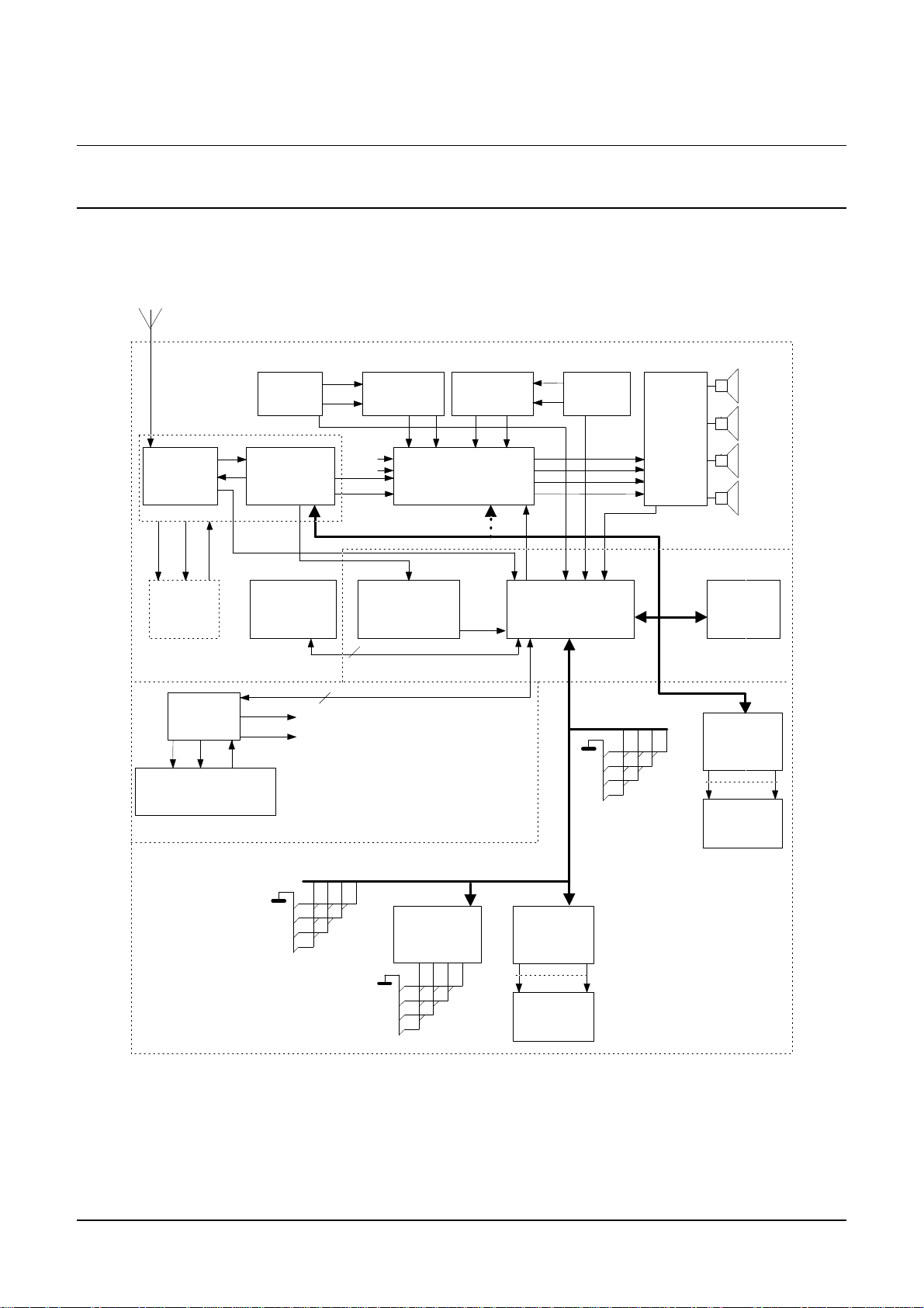
2 HARDWARE CONFIGURATION
2.1 Block diagram CCR612
Figure 1 shows the block diagram of the high-end computer controlled RDS car radio system CCR612.
As can be seen in the block diagram, the system can either be equipped with a fixed keyboard or with a
detachablekeyboard. The detachablekeyboardversionofthesystemstillallowssomekeys to berealised
as fixed keyboard keys. Furthermore a choice exists with respect to the following system parts:
- Power amplifier ( 2 speaker / 4 speaker / output power)
- Sound control (Potentiometer control / I2C control)
This hardware description only describes the use of the sofac TEA6320.
2.1.1 Main Board Part 1a (Basic AM/FM stereo Radio Part)
Page81showsthecircuitdiagramofthebasicradiopart,whichconsistofthefollowingparts:ICEreceiver
module,audio pre-amplifier,power amplifier,power stabiliser, differentialline receiverand PACScontrol
board.
AM/FM - ICE module (TEA6811V,TEA6822T)
The AM/FM - ICE module is a sub-board ( see paragraph 2.1.8)which comprises a two IC package (RF
ICTEA6811VandIFICTEA6822T)and is designed especiallyfor use incar radio’s. Themodule contains
the following functions;
AM receiver
FM receiver
- FM stereo decoder
- Interference Absorption Circuit (or Noise Blanker)
- Station detector and weak signal control
PLL tuning Synthesizer
I2C-Bus control
96029
The complete circuit diagram of the ICE Module (version euro 1) is shown on page 89. For a detailed
description of functions and performance see Ref.4.
Audio Pre Amplifier (TEA6320)
I2C-Buscontrolledaudiopre-amplifierinSOpackageforcarandhomereceivers,includesSourceselector
(forfourstereoinputsandonemonoinput),Loudnesscharacteristic, Volume control, Bass control, Treble
control, Balance and Fader control.
Power Amplifier (TDA8561Q)
Carradio poweramplifier withdynamic distortiondetector and diagnostics in a17 leadsingle inline (SIL)
plastic power package. It contains 4 x 12W (2 ohm)and 4x 7W(4 ohm)single-ended or2 x24W (4 ohm)
bridge amplifiers.
Supply voltage Stabilizer (TDA3602)
Three output voltage regulator, in SIL 9 package, for use in car radios with amicroprocessor. It contains
twocomputer controlledvoltageregulators withfoldback current protection(Regulators 1and 2) andone
fixed voltage regulator (3) that also operates during load dump and thermal shutdown. This regulator is
used to supply the microprocessor.
13
Page 14
Philips Semiconductors
AM/FM-IF
MPX DEC.+IAC
TEA6822T
L
R
LCD
DISPLAY
MAIN IIC -BUS
VOLTAGE
STABILIZER
TDA3602
FM / AM
CASSETTE
CONTROL
INTERFACE
LCD DRIVER
PCF8576
RDS
DEMODULATOR
SAA6579T
RDSCLK
RDSDAT
EEPROM
PCF8594E
-2(P/T)
MICROCONTROLLER
CCR612S
(P83CE528)
AM/F M- RF
PLL-SYN TH
TEA681 1V
AUDIO CONTROL
TEA632x T
OR
TDA152 6
POWER
AMP
TDA8562Q
or
TDA8561Q
(2x)
CDC
INPUT
JACK
ISOLATOR
TDA8579(T)
CASS(L)
CASS(R)
LF
LR
RF
RR
CDC_L
CDC_R
CASS(L)
CASS(R)
TEA0675(T)
or: TEA0677(T)(no dolby)
MAIN uP ,NVM
RDS DEMODULATOR
MAIN BOARD PART 2
DISPLAY PANEL
FIXED KEYBOARD
FRONT-PANEL FP1A/B
KEYBOARD SCAN LINES
EX STATE
8
LCD
DISPLAY
LCD DRIVER
PCF8 576
DETACHABLE
KEYBOARD
SCANNER
PCF8574
KEYBOARD SCAN LINES / DETACH. KEYB IIC-BUS
OR
DISPLAY PANEL
DETACHABLE KEYBOARD
FRONT-PANEL FP1C
HEAD AMPL DOLBY AMS PROC.
AMSDOLBYMECR
CASSETTE INTERFACE
MAIN BOARD PARTS
EXTERNAL
AUDIO
JACK
EX_L
EX_R
ISOLATOR
TDA857 9(T)
CDC_bus
5
PACS
TEA6850
SUB-BOARD
MPXIF
MPX
MONO
DIAG.
BLEEPIn-lock
ICE MODULE
AM/FM RECEIVER
Stereo decoder
Audio Amplifier
Power supply
MAIN BOARD PART 1
User Manual of High-End RDS/EON
Car Radio System CCR612 (V0.3)
Application Note
96029
Figure 1 Block diagram CCR612
14
Page 15

Philips Semiconductors
User Manual of High-End RDS/EON
Application Note
Car Radio System CCR612 (V0.3)
Isolator ( Differential Line Receiver, TDA8579T)
Dual common-mode rejection differential line receiver with 0 dB gain and low distortion. This device is
intendedto be used to receive line inputs in audioapplications thatrequire ahigh levelof common-mode
rejection. The device is encapsulated in an 8-pin SO or DIL package. In this set the isolator is used
between the external input and source selector input. Both the external input plug circuit and the
CD-changer input circuit are equipped with an isolator.
PACS - Sub Board (TEA6850)
PACScontrols theI.F. Selectivity /Bandwidth toavoid receiving problemsdue tonear adjacent channels
(especiallyfor Europe,spacing of100 kHzis notan exception). In order to show theimprovements ofthe
selectivity anddynamic behaviour of the radio by the use of PACS anON/OFF switch has been used on
the front panel.
A complete circuit diagram of the PACS board is shown on page 94 and for description of the functions,
alignment and performance see Ref.5.
2.1.2 Main Board Part 1b (Optional Power Amplifier, 2 x TDA8561Q)
Page 82 shows the previous circuitdiagram (paragraph2.1.1 BasicAM/FM stereo Radio Part) equipped
with circuits for 4 x 24W (4 ohm) audio output power.
96029
Power Amplifier (2 x TDA8561Q)
Single circuit configuration 2 x 24W (4 ohm) bridge amplifiers, package SIL 17 pins Quil.
2.1.3 Main Board Part 1c (Optional Source Sel. & Audio Contr. HEF4052B/TDA1526)
Page83 showsthe circuit diagramfrom paragraph2.1.1 (Basic AM/FMstereo RadioPart) equipped with
the DC controlled audio pre-amplifier (TDA1526) and a source selector circuit (HEF4052B).This set-up
is used in case potentiometer control for volume and tone is desired.
Audio Pre-Amplifier and DC Control (TDA1526).
An active stereo,tone/volume control for car radios. It includes functions for bass and treble, control,
volumecontrolwithbuiltincontour(can be switched off)and balance.All thesefunctions can becontrolled
direct by DC voltages or via single linear potentiometers.
Source selector circuit (HEF4052B).
TheHEF4052Bis a dual 4channelanaloguemultiplexer/demultiplexerwithcommonchannelselectlogic.
In this case used for four stereo inputs: radio, cassette and external input.
15
Page 16

Philips Semiconductors
User Manual of High-End RDS/EON
Application Note
Car Radio System CCR612 (V0.3)
2.1.4 Main Board Part 2a ( Micro-controller, EEPROM and RDS Demodulator)
Page 84 shows the circuit diagram of the RDS Demodulator, Micro controller (which combines all radio
control functions as well as RDS decoding) and EEPROM.
Microcontroller (P83CE528EFB)
Main microcontroller (CCR612S), a derivative of the 8051 micro-controller family with an 8-bit CPU, 32
Kbytes ROM, 512 bytes RAM and four 8-bits I/O ports in a 44-pins QFP package.
EEPROM (PCF8594E-2P/T)
ThePCF8594E isa512byte,5VElectricallyErasableProgrammableReadOnlyMemory (EEPROM)that
can be 100,000 times re-written. I2C-bus controlled.
RDS Demodulator (SAA6579T)
RDS Demodulator IC, which includes the 57 kHz band-pass-filter, to generate the RDS data out of the
MPX signal.
2.1.5 Main Board Part 2b (Detachable Front)
Page85shows thepreviouscircuitdiagram (paragraph2.1.4) ofthemicro controller boardextendedwith
the possibility to use a detachable front panel.
96029
2.1.6 Main Board Part 3 (Cassette Interface including Dolby B*)
Page 86shows the circuit diagram of the cassette interface circuit for the Philips cassette deck P6-29/3.
Thecircuitis based ontheTEA0675,Dual Dolby* B-typenoisereductioncircuit for playbackapplications.
The TEA0675 includes head and equalization amplifiers with electronically switchable time constants.
Furthermore the TEA0675 includes electronically switchable inputs for tape drives with reverse heads.
This device also detects pauses of music in the AMS (Automatic Music Search) scan mode.
16
Page 17

Philips Semiconductors
User Manual of High-End RDS/EON
Application Note
Car Radio System CCR612 (V0.3)
2.1.7 Front Panels
2.1.7.1 Front Panel Part FP-1a (Key and Display panel)
Page 87 shows the circuit diagram of the key and display panel.
LCD Driver (PCT8576CT)
ThePCF8576isa peripheral devicewhichinterfacestoalmost any liquidcrystal display(LCD)havinglow
multiplex rates. It generates the drive signals for any static or multiplex LCD containing up to four back
planes and up to 40/24 segments and can easily be cascaded for larger LCD applications. I2C-bus
controlled.
2.1.7.2 Front Panel Part FP-1b (Detachable Front Version).
Page88 shows thecircuit diagram ofthe detachablekeyboardfront. Thecircuitincludes anI/Oexpander
PCF8574, the keyboard and LCD display unit are placed on thedetachable front controlled by a second
I2C bus. Eight contacts are required to connect the detachable front to the radio. Furthermore there is a
fixed key-board with alimited number of keys included.That means it is possibleto use a combination of
detachable keys and fixed keys (for circuit example see page 85).
96029
2.1.8 Diagram ICE module.
Standard Version EURO 1
Page 89 shows the complete circuit diagram of the ICE AM/FM tuner module version Euro 1.
The Standard Euro 1 module is intended for European frequency ranges.
FM 87.5 to 108.0 MHz
AM (MW) 531 to 1629 kHz
AM (LW) 144 to 288 kHz
The module contains the IC’s TEA6811V and TEA6822T with the following main functions;
TEA6811 - AM RF TEA6822 -2ndAM mixer
- AM mixer - 2ndFM mixer
- FM mixer - AM/FM - IF amplifier
- AM/FM oscillator - AM and FM demodulator
- Tuning synthesizer - x-tal oscillator (61.5 MHz)
-I2C-Bus - Stereo Decoder and IAC
- Station (stop) detector
- Weak signal processing
- Multi Path Detector
-I2C-Bus
17
Page 18

Philips Semiconductors
User Manual of High-End RDS/EON
Application Note
Car Radio System CCR612 (V0.3)
EURO 2, USA 1 and JAPAN 1 ICE MODULE VERSIONS.
By slight circuit modifications of the standard module (EURO 1), matched module versions with better
performance for e.g. USA an Japan can be derived. The needed modifications for the different modules
are:
Module Version Modifications.
Euro 1 Non
Euro 2 (including S.W.) A short wave transformer i.s.o. L8 and C29
USA 1 L15 short circuited
C2 10pF i.s.o. 5p6
C72 6p8 deleted
R18 1 Mohm i.s.o. 220 Kohm
R54, in parallel with C26 (1uF)
C61 10 nF i.s.o. 6n8
C62 10 nF i.s.o. 6n8
Z1 SFR450H i.s.o. SFP 450H
Z3 SFE 10.7 MS3 G-A 220 kHz i.s.o. SFE10.7 MS3 A 10k-A
Z2 & Z4 SFE 10.7 MS2 G-A 180 kHz i.s.o. SFE10.7 MS3 A 10k-A
R41 (pre-set adjust) replaced by resistor of 68 Kohm.
R44 120 Kohm i.s.o. 82 Kohm.
96029
Japan 1 C7 47 pF i.s.o. 180pF
C9 deleted
D3 BB814 selection i.s.o. BB804
2.1.9 Diagram PACS Sub Board
Page 94 shows the diagram of the PACS Sub-Board using the TEA6850. For circuit description,
performance and PCB lay out see application note Ref.5.
2.1.10 PCB LAY-OUTS of CCR612 sample Version D.
CCR612/Mainboard PCB lay-out TOPside Copper (p.90, fig. a) / Components (non SMD) (p.90, fig. b)
CCR612/Mainboard PCB lay-out BOTTOM side Copper(p. 91, fig. c) / SMD Components (p. 91, fig.d)
ICE module board PCB lay-out TOP side Copper(p. 92, fig. a) /Components (non SMD) (p. 92, fig. b)
ICE module board PCB lay-out Bottom side Copper(p. 92, fig. c) / SMD Components (p. 92, fig. d)
Front panel PCB lay-out Top side Copper (p. 93, fig. a) / Components (non SMD) (p. 93, fig. b)
Front panel PCB lay-out Bottom side Copper (p. 93, fig. c) / SMD Components (p. 93, fig. d).
18
Page 19

Philips Semiconductors
User Manual of High-End RDS/EON
Car Radio System CCR612 (V0.3)
2.2 Performance of the radio
General
Supply voltage range 10.2 to 16 V
Quiescent current: power off < 2 mA (typ.)
power on 550 mA (typ.)
Operating ambient temperature -30 to 80 °C
FM frequency range: Europe 87.5 to 108.0 MHz
USA 87.9 to 107.9 MHz
AM frequency range: Europe 144 to 288 kHz (LW)
531 to 1629 kHz (MW)
5900 to 6200 kHz (SW)
USA 530 to 1710 kHz (MW)
5900 to 6200 kHz (SW)
Application Note
96029
IF-frequency double conversion: FM-IF1/IF2 72.2MHz / 10.7 MHz
AM-IF1/IF2 10.7 MHz / 450 kHz
19
Page 20

Philips Semiconductors
User Manual of High-End RDS/EON
Car Radio System CCR612 (V0.3)
FM characteristics
V
=14.4V, T
supply
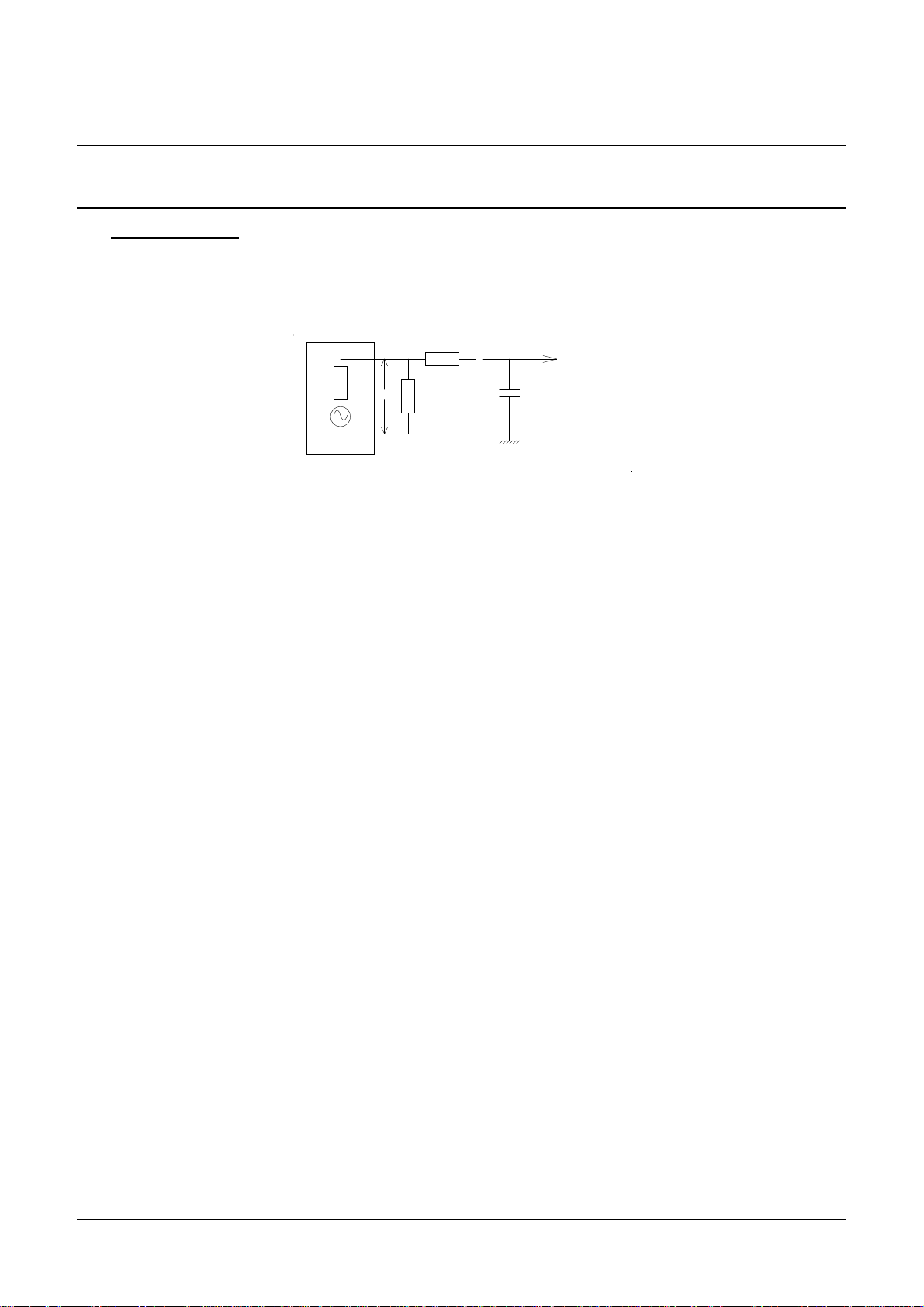
aerial as shown in Figure 2.
Aerial input voltage (Vin), for -3 dB limiting (adjustable) 3 - 20 µV
for (S+N)/N = 26 dB 2.7 µV
for 10 dB crosstalk (stereo) 70 µV
Signal-to-noise ratio over most of the signal range 64 dB
RF signal handling capability for THD < 2% at 75kHz dev. > 2 V
=25°C,fo=98MHz, f
amb
Signal gen er ator
Figure 2 Dummy aerial to test the FM mode
50
=±22.5kHz, f
dev
Vin
=1kHz unlessotherwisespecified.Dummy
mod
1204.3
Radio aerial
input (150 O hm)
55
Application Note
96029
MPX output (RMS value) at pin 47 of the TEA6822 200 mV
AM suppression over most of the signal range > 55 dB
Total Harmonic Distortion over most of the signal range. 75 kHz dev. 0.5 % (typ.)
Adjacent signal selectivity (two signal method) S
200
>45 dB
IF suppression: IF1 (72.2 MHz) > 70 dB
IF2 (10.7 MHz) > 90 dB
Search sensitivity (adjustable) Vin > 4 µV
RDS sensitivity: Traffic Announcement Vin > 12 µV
Programme Identification Vin > 15 µV
IF counter resolution 6.25 kHz
Frequency grid (Europe): Search Tuning 100 kHz
Manual Tuning 50 kHz
Repetitive Manual tuning (after .5s) 100 kHz
Frequency grid (USA): SearchTuning 200 kHz
Manual Tuning 100 kHz
Repetitive Manual tuning (after .5s) 200 kHz
20
Page 21
Philips Semiconductors
50
60
50
Signal generator
Vin
Radio aerial input
65 pF
15 pF
User Manual of High-End RDS/EON
Car Radio System CCR612 (V0.3)
AM characteristics
V
=14.4 V,T
supply
as shown in Figure 3.
Aerial input voltage (Vin),
for (S+N)/N = 26 dB MW 55 µV
=25°C, fo=999 kHz,m = 0.3, f
amb
=1 kHzunless otherwisespecified. Dummyaerial
mod
Figure 3 Dummy aerial to test the AM mode
LW 80 µV
SW t.b.f.
Application Note
96029
Signal-to-noise ratio for Vin=1mV > 55 dB
AGC range 5 mV/Vin for 10 dB variation of AF output > 60 dB
RF signal handling capability for THD < 10 % at m = 0.8 > 3 V
Total Harmonic Distortion over most of the
AGC range, m = 0.8, fmod = 1 kHz < 2 %
Total bandwidth B 3dB 4.5 kHz
Fidelity ( -3 dB ) 10 Hz - 2 kHz
IF suppression IF1 (10.7 MHz) > 70 dB
IF2 (450 KHz) > 100 dB
IF selectivity S
S
9
18
>55 dB
>60 dB
IF counter resolution 250 Hz
21
Page 22

Philips Semiconductors
User Manual of High-End RDS/EON
Car Radio System CCR612 (V0.3)
Frequency grid Europe
LW (search and manual tuning) 1 kHz
MW (search and manual tuning) 9 kHz
SW (search and manual tuning) 1 kHz
USA
MW (search and manual tuning) 10 kHz
SW (search and manual tuning) 1 kHz
Search sensitivity (adjustable) > 20 µV
Application Note
96029
22
Page 23

Philips Semiconductors
User Manual of High-End RDS/EON
Car Radio System CCR612 (V0.3)
3 SHORT SPECIFICATION
Tuning
Frequency bands:
Optionally the following frequency bands are used:
FM: 87.50 - 108.00 MHz (50/ 100 kHz steps) }
MW: 531 - 1629 kHz (9 kHz steps) } For application in Europe
LW: 144 - 288 kHz (1 kHz steps) }
SW: 5.9 - 6.2 MHz (1 kHz steps) }
FM: 87.90 - 107.90 MHz (100/ 200 kHz steps) }
MW: 530 - 1710 kHz (10 kHz steps) } For application in USA
SW: 5.9 - 6.2 MHz (1 kHz steps) }
PLL tuning principle
Manual tuning up / down
First one step, next after 0.5 seconds. Fast repetition at 12.5 times per second.
Application Note
96029
Local/Dx switching
The Local/Dx feature controls the search sensitivity. Default after switching on is always Dx.
In the TEA6811 a tuner attenuator for the FM-band is incorporated.
Search tuning up / down
Sensitivity is controlled by Local/Dx. If after one complete band sweep in Local mode no station is
found,the radioswitches automatically toDx. Duringsearch tuning therunning frequencyis displayed
and the radio is muted.
Frequency Scan
Continuous automatic search tuning, pausing for 6 seconds on every station.
AST (Automatic Store Tuning) for FM and MW band
AST switches to FM-AST or MW-AST band, searches for the6 strongest transmittersin the band and
stores them in the AST programme preset memory. In FM, duplication of PI codes will be avoided.
Programme preset memory
For each band (FM1, FM2, MW, LW, SW (49m), FM-AST and MW-AST) 6 programme presets and a
"manual" frequency are stored. In FM, additional RDS information is stored: PI code (Programme
Identification), PS name (Programme Service), AF list (Alternative Frequencies) and AF follow mode
on/off.
Whenever another band is selected, the radio reverts to the last frequency tuned to in the new band
(this can be either a preset frequency or a manually tuned frequency).
Programme preset up / down control
Programme presets can be stored and recalled by two key control (up and down) or by 6 separate
preset keys.
23
Page 24

Philips Semiconductors
User Manual of High-End RDS/EON
Application Note
Car Radio System CCR612 (V0.3)
AF follow mode
WhenAFfollowmode is on,the setwill regularlymeasure thesignalstrengthofalternativefrequencies
and compare it with the current station. If an alternative frequency offers better quality, the radio will
switch over and update the alternative frequency list. The measuring scheme is designed to cause
minimumnoticeabledisturbanceforthelistener.Theintervaltimebetweentwomeasurementsdepends
on the signal quality.
Intelligent preset programme recall
If an FM programme preset witha known PI code isrecalled, theprimary frequency and all alternative
frequenciesstoredinthe programme presetmemory areexamined.Thefrequencywith the bestsignal
qualitybroadcastingthecorrectPIcode will beselected. Only whenthe programme isnot foundon one
of the AFs, after 6 seconds a search is started for a station with a proper PI code.
TA mode
In TA mode the radio only searches for transmitters that transmit the RDS traffic programme on the
same station or on EON linked stations.The radio willautomatically start asearch when switching TA
mode on and the current station is not a traffic station.
PTY scan mode
In PTY scan mode the radio searches for transmitters that transmit the user-selected PTY code.
Dependentonthefactoryoption USA/Europe the RBDSPTY-table or theRDS PTY-tableis used.Only
English PTY messages are available.
96029
Laststatusmemory: band, frequency,PI code,AFfollowmode on/off statusand TAmodeon/offstatus
are stored in memory. This status is recalled during switch on.
RDS
Bit, block and group synchronisation. (inclusive RBDS E-block detection).
Data collection and decoding of:
- PI, Programme Identification code
- AF, Alternative Frequencies
- TP, Traffic Programme
- TA, Traffic Announcement
- PS, ProgrammeService name
- PTY, Programme TYpe
- EON, Enhanced Other Network
AF follow mode using PI and AF (see also Tuning).
Display of the programme service name in 8 alpha-numeric characters (PS name).
Display of AF, TP, TA, PTY, EON and Regional mode status via icons.
Regional mode on/off switching. When Regional mode is on, the radio will, during AF switching, only
switch over to stations with exactly the same PI-code. When Regional mode is off, the radio will also
24
Page 25

Philips Semiconductors
User Manual of High-End RDS/EON
Application Note
Car Radio System CCR612 (V0.3)
switch over to stations broadcasting regional variants of the original station. (so called "generic" or
"family"PI codes). For USA application (RBDS) the regional function will only work for PI codesabove
B000
with exactly the same PI code.
Break-inoftraffic announcements ispossible iftheTAoption is switchedon.ThePTY alarm messages
break-in always. Break in is possible even when the radio is muted or in CD-changer / cassette /
external mode.
User Control
Upto27Localcontrolkeysoneither a fixed, a detachablekeyboard or acombination. Triangular matrix
using 7 lines.
Detachable front
Optionally, the keyboard and the LCD display unit can be placed on a detachable front controlled by
a2ndI2C bus.Only 5 contacts are required to connect the detachable front (6 if it hosts also the power
key). No extra hardware is required to detect its presence.
. PI codes below B000
hex
do not have regional variants. Af switching is only allowed to stations
hex
96029
EON
If the TA option is on, switch temporarily to an other station if EON information indicates a traffic
announcementonanothernetworkevenwhentheradioismutedorinCD-changer/cassette / external
mode.
Maintain lists of alternative frequencies of other stations stored in preset memory with information
received via EON on the currently tuned station.
Displayby means ofan iconwhether EON datais received andwhether an EONtraffic announcement
is broadcast.
Display
143 Segment LCD with Umlaut (ü) characters, 1:4 multiplexed divided into:
8 Alphanumeric characters + decimal point are used to display:
- Band and frequency (Example: "FM 103.50")
- Indication "BALANCE", "FADER", "TREBLE", "BASS" and their value.
- RDS programme service name (PS) in 8 alphanumeric characters.
- RDS programme type (PTY)
- "MUTE", in case the user mutes the radio, cassette or external
- Cassette mode function such as "PLAY >", "CAS WIND", etc.
- CD-changer messages such as "CD 01.23" , "CHANGER " etc.
7 Segment display for the current programme preset number.
25
Page 26

Philips Semiconductors
User Manual of High-End RDS/EON
Application Note
Car Radio System CCR612 (V0.3)
15 Icons for display of:
- ST On when stereo pilot signal is detected and the radio is not in forced mono mode.
- AST Onwhen AST band is selected.
- SCAN On when in Frequency scan mode.
- AF On when AF follow mode is enabled (see also Tuning), flashing if no RDS data
received.
- TA On in TA mode and flashing during a traffic announcement in progress.
- TP On when a traffic station is received, flashing when the station is not a traffic station
and TA mode is on.
- PTY Onwhen a PTY code is received, flashing during PTY search.
- DOLBY On in cassette mode when dolby is on.
- MTL On in cassette mode when metal/chrome is selected.
- AMS On in cassette mode when AMS is on.
- REG On when the radio is in regional mode (see also RDS)
- EON On when EON data is received, flashing during an EON traffic announcement.
- LOC On when the radio is in Local mode (see also Tuning)
- LOUD On when Loudness is on.
- CLIP On when clipping is detected and clipping control is active.
96029
Non Volatile Memory
512 bytes EEPROM. The following information is stored in NVM:
System status e.g.: band, audio source (radio / CD-changer / cassette / external).
For each band FM1, FM2, FM-AST, MW, MW-AST, LW, SW(49m) : 6 preset frequencies, one non-
preset frequency and the last used preset number.
For each FM preset:
- PI-code
- PS Name
- AF List (9 AF’s)
- AF follow mode on/off.
Audio controls: volume, bass, treble, balance, fader and loudness.
Preprogramming EEPROM
At power-on the contents of the NVM is checked, when a non-initialized EEPROM is detected, the
EEPROM will be preprogrammed with default values.
Appendix II lists the default values written to NVM during initialization.
Sound
Volume, bass, treble, balance and fader control with VOL-UP / VOL-DOWN keys.
Analog control select key to cycle through bass, treble, balance and fader.
Mute function.
Automatic muting during tuning and AST search (silent tuning).
Break-inof trafficannouncements and PTY-alarmmessages (atincreased volume level,which isuser
programmable) when the radio is muted or in cassette / external mode.
Loudness function.
26
Page 27

Philips Semiconductors
User Manual of High-End RDS/EON
Application Note
Car Radio System CCR612 (V0.3)
Sound settings are stored at switch-off and recalled at switch-on.
"Bleep" tone to confirm user actions such as storing a programme preset, entering AST mode, etc.
Mono / stereo function.
Output pins for mute, loudness and traffic announcement, for use with conventional audio control
circuitry.
Automatic mute of radio during "Phone mute" detection.
Power-amplifier
Power-amplifiers with diagnostic facilities
*1×TDA8561Q amplifier for 4 ×12W(2Ωload) or 4 ×7 W or 2 × 24 W bridged application.(both at
4Ω load)
*1×TDA8562Q amplifier for 4 × 12W(2Ωload) or 4 × 7W(4Ωload)
*2×TDA8561Q amplifier for 4 × 24 W bridged application. (4Ω load)
Diagnostic control:
* short-circuit or too high temperature detection, display an error message
* signal clipping, via an icon and stepwise decrease of bass and or volume
Optional conventional power-amplifiers (without diagnostics) can be used such as two TDA1552Q for
4 × 22 W, one TDA1554Q for 4 × 11W(2Ωload) or 4 × 6W(4Ωload) or one TDA1552Q 2 × 22Win
a BTL stereo configuration.
96029
Options
Diode programmable
- Detachable front
- Available frequency bands
- Static on/off switch
- Frequency band limits and tuning grid for different parts of the world. This option also selects
between RDS (Europe) and RBDS (USA).
User programmable
- 2 / 4 Loudspeakers
- Loudness on / off
- TA volume level
Automatically detected
- Digital sound control chip or conventional audio control circuitry
- Loudness
- AMS }
- Dolby } Cassette deck functions
- MTL }
- Presence of the CD-changer (check during power-on)
- Availability of a power amplifier with diagnostics facilities
27
Page 28

Philips Semiconductors
User Manual of High-End RDS/EON
Application Note
Car Radio System CCR612 (V0.3)
Power connections
Continuous power supply input. Normally connected directly to the car battery. All supply power is
drawn from this supply.
Ignition key input. Normally connected to the accessory contact of the ignition switch. Used only for
switchingthe radioon/off. This inputis alsoused when the static on/offswitch optionis chosen instead
of the momentary on/off key.
Switching on/off
Recallof last system status (e.g.:frequency,band,soundcontrolsettings,RDSstatusandlastselected
audio source).
Switch on by:
- Power key, can be static or momentary.
- Ignition contact (after the set was switched off by turning the ignition contact off).
Switch off by:
- Power key, can be static or momentary.
- Ignition contact.
- Removal of detachable keyboard.
When switched on while the ignition contact is (and remains) off, the set will automatically switch off
after 60 minutes.
The radio will switch on again when switched off due to a power dip during engine start.
96029
CD-changer
Radio/CD-changer/Cassette/External mode key.
Disc up/down keys for selecting the next/previous disc.
Track up/down keys for selecting the next/previous track.
Fast forward/reverse keys for jumping some grooves forward/backward.
Shuffle on/off key, for playing the tracks in random order. (The user can make a selection between
tracks on the current disc only or tracks on all discs.)
Repeat on/off key, for repetitive play of the current track or the current disc.
Intro-scankey.When Intro-scan modeison, each trackofthecurrent disc orthefirst track ofeverydisc
(user selectable) are played for 10 seconds in successive order.
28
Page 29

Philips Semiconductors
User Manual of High-End RDS/EON
Application Note
Car Radio System CCR612 (V0.3)
Cassette
Automatically switches to cassette mode after insertion of a tape
Interfaces with a mechanically controlled cassette deck
Play/wind mode detection
Play direction detection for auto-reverse cassette decks
Cassette solenoid control
AMS pause detection for full AMS control
Radio sound during cassette winding
MTL on/off key
DOLBY on/off key
AMS on/off key
CD-changer/Cassette/Radio/External mode key
Optional source switching to externalmode (external plugis in) or always to radio mode (option diode
D6 is present) when the tape is ejected.
External audio input:
Automatically switches to external audio source when a connector is inserted.
CD-changer/External/radio/Cassette mode key.
Optional source switching to cassette mode (tape is in) or always to radio mode (option diode D6 is
present) when the external plug is removed.
96029
29
Page 30

Philips Semiconductors
1
2
3
4
5
6
7
8
9
10
11
12
14
13
15
1617181920
21
22
23
25
24
26
27
28
29
30
31
32
33
34
35
36
37
38
39
40
41
42
43
44
P1.5
P1.6
RST
P3.1
P3.2
P3.3
P3.4
P3.5
P3.6
P3.7
XTAL2
XTAL1
P2.0
P2.1
P2.2
P2.3
P2.4
P2.5
P2.6
P2.7
PSEN
ALE
EA
P0.7
P0.6
P0.5
P0.4
P0.3
P0.2
P0.1
P0.0
Vdd
P1.0
P1.1
P1.2
P1.3
P1.4
EXSTAT
SCL
SDA
P1.7
RESE T
CMTL
CDC_bu s
BLPTST
CDOLBY
KEYB5_FSDA
PSEN
ALE
EA
ON
TA
SEL1_PAUSE
DIAG
Vdd
CDIR
CINDRV
IGN
CPLYWD
LOUD
AUMUTE
CENABL
XTAL2
XTAL1
SEL0_SOLND
KEYB0
Vss
Vss
KEYB6_FSCL
RDSDAT
RDSCL K
Vss
P3.0
Vss
VssVss
Vss
Vss
Vdd
Vdd
KEYB1
KEYB2
KEYB4
HOLD
OPTROW
(P83CE528)
CCR612S
CAMS
PLL_LOCK
KEYB3
User Manual of High-End RDS/EON
Application Note
Car Radio System CCR612 (V0.3)
4 CCR612S PINNING AND INTERFACING
CCR612S is accommodated in a P83CE528 microcontroller in a 44-pins Quad Flat Package. It is
manufacturedin CMOS technology and is a derivative of the 80C51 microcontroller family. It contains 32
kbytes of ROM and 512 bytes of RAM.
For electrical characteristics of I/O pins, see the P83CE528 data sheet.
4.1 Pinning overview
Whenthe radio is equipped witha detachablekeyboard, pinsKEYB5_FSDA & KEYB6_FSCL (pins 23 &
24) are used as I2C-bus lines to the detachablekeyboard. Otherwise pin23 and pin 24 are used as scan
lines for the fixed keyboard.
96029
Figure 4 Pinning of CCR612S
In case of conventional audio sound control circuitry, pin SEL0_SOLND and SEL1_PAUSE are used to
select between the various audio sources (radio, CD-changer, cassette, external output) by means of a
dual 4 channel analogue multiplexer (e.g. HEF4052B). If a TEA632x is installed these pins can be used
for respectively solenoid control and AMS pause input control.
30
Page 31

Philips Semiconductors
User Manual of High-End RDS/EON
Application Note
Car Radio System CCR612 (V0.3)
The next tables give a description of the function of all pins.
Legend for pin types: OD Open Drain
IP InternalPull up resistor
1 Can sink 1 TTL load (or 4 LSTTL)
2 Can sink 2 TTL loads (or 8 LSTTL)
Pinning CCR612S
Pin Name I/O Type Description
1 EXSTAT I IP 1 Indicates whether external audio source is connected.
High: external audio source is not connected
Low: external audio source is connected
2 SCL I/O OD 2 Clock line of I2C bus
3 SDA I/O OD 2 Data line of I2C bus
4 RESET I Normally low. To start the microcontroller, a high pulse of
at least 20 milliseconds must be applied to this pin.
96029
A reset pulse must be applied when:
- Power is applied to the radio
- The power key is pressed while the radio is off
- The ignition contact is switched on while the radio is off
The reset input is normally connected to the reset and hold
outputs of the power stabiliser TDA3602, via a capacitor
and a diode.
5 CMTL O
6 Vss Ground
7 CAMS O
IP 1 Cassette Metal (versus Chrome/Ferro) mode
High: Ferro/Chrome selected
Low: Metal selected
I
IP 1 Automatic Music Search
If the cassette deck does not have this function, the pin
must be connected to Vdd.
High: AMS is active
Low: AMS is inactive
I
If the cassette deck does not have this function, the pin
must be connected to ground.
31
Page 32

Philips Semiconductors
User Manual of High-End RDS/EON
Application Note
Car Radio System CCR612 (V0.3)
Pinning CCR612S
Pin Name I/O Type Description
8 RDSCLK I IP 1 RDS Clock line. Connected to clock output pin of RDS
demodulator SAA6579
9 CDC_bus I IP 1 CD-changer bus. The CDC_bus is a bi-directional bus
which allows the CD-changer and the radio to exchange
commands and status information.
10 BLPTST O
11 CDOLBY O
IP 1 1. Bleep tone output signal. Normally high. This pin
outputs the bleep tones.
I
IP 1 Cassette Dolby mode
2. When pulled low externally, service mode is entered.
The microcontroller stops all I2C bus transfers after
completion of the last user action (within 0.5 sec.
except for search tuning). This feature can be used for
factory testing and programming the NVM before the
radio leaves the factory.
High: Dolby not selected
Low: Dolby selected
96029
I
12 RDSDAT I IP 1 RDS Data line. Connected to data output pin of RDS
13 SEL0_
SOLENOID
1415XTAL2
XTAL1
16 Vss Ground
O
IP 1 SEL0 (no TEA632x installed). Source selection
O
I
O
I
If the cassette deck does not have this function, the pin
must be connected to Vdd.
demodulator SAA6579.
Sel1 Sel0
0 0 CD-changer source selected
0 1 Cassette source selected
1 0 External source selected
1 1 Radio source selected
SOLENOID (TEA632x installed). Cassette solenoid
High: Solenoid in standby position
Low: Solenoid is locked
If the cassette deck does not have this function, the pin
must be connected to ground.
A 12 MHz crystal is connected between these pins,
controlling the internal clock oscillator. When an external
clock is used, it must be applied to XTAL1.
17 Vdd Power supply: + 5V
18-
24
IP 1 Keyboard scan lines. Pin assignments are different for
fixed front and detachable front. See relevant tables at the
end of this section.
32
Page 33

Philips Semiconductors
User Manual of High-End RDS/EON
Application Note
Car Radio System CCR612 (V0.3)
Pinning CCR612S
Pin Name I/O Type Description
25 HOLD I IP 1 Connected to the hold output pin of the voltage stabilizer
TDA3602. This pin is used to check for power failures.
26 /PSEN O Program Store Enable output, used when the
microcontroller runs code from an external memory. Not
used by the CCR612S system. The pin will always be high.
27 ALE O Address Latch Enable output, used when the
microcontroller accesses external memory. Not used by
the CCR612S system. This pin should not be connected.
In the EMC improved microprocessors (P83CE528) this
pin is muted.
28 Vss Ground
29 /EA I External Access input. Should be held high (with a pull-up
resistor) to ensure that the microcontroller runs from
internal program memory (ROM).
30 ON O OD 2 Controls the voltage stabiliser TDA3602
96029
31 TA O
High: Switch supply voltages off (TDA3602 in "coma"
state)
Low: Switch supply voltages on (TDA3602 in "on"
state)
OD 2 Traffic Announcement indication
High: No traffic announcement
Low: Traffic announcement or PTY alarm message in
progress
This pin can be used to raise the volume setting during
traffic announcements and PTY alarm messages in case
no digital sound control IC is used.
I
Option diode for static on/off switch detection.
33
Page 34

Philips Semiconductors
User Manual of High-End RDS/EON
Car Radio System CCR612 (V0.3)
Pinning CCR612S
Pin Name I/O Type Description
32 SEL1_
PAUSE
33 DIAG I
O
OD 2 SEL1 (no TEA632x installed). Source selection
Sel1 Sel0
0 0 CD-changer source selected
0 1 Cassette source selected
1 0 External source selected
1 1 Radio source selected
I
OD 2 Power amplifiers diagnostics input.
PAUSE (TEA632x installed). Cassette AMS pause
High: No pause detected
Low: Pause detected
If the cassette deck does not have this function, the pin
must be connected to ground.
High: Normal mode
Low: Clipping, overheated or shortcircuit.
Application Note
96029
I
34 CDIR I OD 2 Indicates the play direction of the cassette deck. Used to
35 CINDRV I OD 2 Indicates whether a tape is in the cassette drive. Used to
36 IGN I OD 2 Indicates status of ignition contact or the static on/off
37 CPLYWD I OD 2 Indicates play/wind status of cassette deck. Used to switch
If no diagnostics facilities are available this pin should be
connect to Vdd.
show the play direction on the display
High: Reverse ( <- arrow displayed)
Low: Forward ( -> arrow displayed)
switch to cassette mode when a tape is inserted.
High: No tape in drive
Low: Tape in drive
switch (when this option is chosen). Used to switch the set
on or off.
High: Ignition contact / static switch on
Low: Ignition contact / static switch off
to radio reception during winding.
High: Wind
Low: Play
38 Vdd Power supply: + 5V
34
Page 35

Philips Semiconductors
User Manual of High-End RDS/EON
Application Note
Car Radio System CCR612 (V0.3)
Pinning CCR612S
Pin Name I/O Type Description
39 Vss Ground
40 OPTROW O IP 1 Connected to the cathodes of all option diodes. During
switch on, this pin is pulled low by the microcontroller to
find out which option diodes are present.
41 PLL_LOCK I IP 1 PLL In Lock detection.
High: Tuner is in lock.
Low: Tuner is not in lock.
42 LOUD O
IP 1 Loudness control. This pin can be used to switch loudness
on/off in case no digital sound control IC is used.
High: Loudness off
Low: Loudness on
I
loudness control is not available when this pin is
connected to ground.
96029
43 AUMUTE O
44 CENABL O
IP 1 General mute control. This pin can be used to control
general audio muting in case no sound control IC is used.
High: Not muted
Low: Muted
I
I
IP 1 Cassette Enable. Controls the cassette deck motor.
I
Phone mute input
High: No phone mute request
Low: Phone mute request
Option diode available bands 1
High: Cassette motor off
Low: Cassette motor on
Option diode for detachable keyboard detection.
35
Page 36

Philips Semiconductors
User Manual of High-End RDS/EON
Car Radio System CCR612 (V0.3)
Pins 18 to 24 of CCR612 with fixed front.
Pin Name I/O Type Description
18 KEYB0 I/O IP 1 Line of the triangular keyboard matrix
19 KEYB1 I/O IP 1 Line of the triangular keyboard matrix
20 KEYB2 I/OIIP 1 Line of the triangular keyboard matrix
Option diode for tuning grid and band limits (USA / Europe
option)
21 KEYB3 I/OIIP 1 Line of the triangular keyboard matrix
Option diode for available bands.
22 KEYB4 I/O IP 1 Line of the triangular keyboard matrix
23 KEYB5 I/O IP 1 Line of the triangular keyboard matrix
24 KEYB6 I/O IP 1 Line of the triangular keyboard matrix
Application Note
96029
Thefixed keyboard (See Figure 6) is scanned every 10milliseconds. Toscan thekeyboard, thelines are
madelow -one at atime -andthen thestate of theother linesare read. Fordebouncing, akeypress must
be detected 3 times before it is accepted.
36
Page 37

Philips Semiconductors
User Manual of High-End RDS/EON
Car Radio System CCR612 (V0.3)
Pins 18-24 of CCR612 with detachable front
Pin Name I/O Type Description
18 KEYB0 I/O IP 1 Line of the triangular keyboard matrix
19 KEYB1 I/O IP 1 Line of the triangular keyboard matrix
20 KEYB2 I/OIIP 1 Line of the triangular keyboard matrix
Option diode for tuning grid and band limits (USA / Europe
option)
21 KEYB3 I/OIIP 1 Line of the triangular keyboard matrix
Option diode for available bands.
22 KEYB4 I/O IP 1 Line of the triangular keyboard matrix
These lines form a small extra triangular keyboard matrix.
(See Figure 7). This keyboard is scanned every 10
milliseconds. To scan the keyboard, the lines are made
low - one at a time - and then the state of the other lines
are read. For debouncing, a keypress must be detected 3
times before it is accepted.
Application Note
96029
23 SDA_
FRONT
24 SCL_
FRONT
This keyboard can be used optional together with the
detachable keyboard.
The power key should always be available in this
keyboard but not when the static on/off switch option is
used.
I/O IP 1 Data line of front panel I2C bus.
The detachable front has a separate I2C bus, for which
measures may be taken to reduce interference and to
improve immunity for static charges. It also isolates radio
circuitry from the externally accessible contacts.
The front panel I2C bus controls the display driver and the
8-bit bi-directional I/O expander to which the keyboard
matrix is detected.
I/O IP 1 Clock line of front panel I2C bus.
37
Page 38

Philips Semiconductors
User Manual of High-End RDS/EON
Application Note
Car Radio System CCR612 (V0.3)
4.2 Factory options
4.2.1 Diode options
The following options can be selected by means of option diodes:
Diode Pin Description
D1 44 Detachable keyboard is available. (diode present)
D2/D3 21/43 Diode D2 Diode D3 Available bands
Not present Not Present FM, MW, LW
Present Not Present FM
Not present Present FM, MW
Present Present FM, MW, LW, SW(49m)
D4 No used in CCR612S
D5 31 Static on/off switch. (diode present)
D6 Not used in CCR612S
D7 20 Tuning grid and band limits for USA application are selected (diode present).
LW band is disabled and the RBDS PTY code table is selected.
96029
1
2
3
4
5
6
7
8
9
10
11
AUMUTE
CENABLE
44
P1.3
P1.4
P1.5
P1.6
P1.7
RST
P3.0
Vss
P3.1
P3.2
P3.3
P3.4
P3.5
P3.7
P3.6
12141315161718
OPTROW
P1.0
P1.1
P1.2
CCR612S
(P83CE528)
XTAL2
XTAL1
Vss
D3
37383940414243
P0.1
P0.0
Vdd
Vss
P2.0
P2.1
P2.2
Vdd
192021
KEYB2
P0.2
P2.3
KEYB3
343536
22
P0.3
P0.4
P0.5
P0.6
P0.7
EA
Vss
ALE
PSEN
P2.7
P2.6
P2.5
P2.4
D1
D5
D2
33
32
31
TA
30
29
28
27
26
25
24
23
D7
Figure 5 Connection of Option Diodes
38
Page 39

Philips Semiconductors
User Manual of High-End RDS/EON
Application Note
Car Radio System CCR612 (V0.3)
4.2.2 Automatically detected options
CCR612S will detect the following options automatically:
Digital sound control chip.
Presence / absence of a sound control chip (TEA632x) is detected by testing its I2C bus address.
NOTE: The output pins AUMUTE,LOUDN and TAare always operational,even when a digital sound
control chip is installed. Cassette solenoid and AMS pause control functions are not available in case
no TEA632x is installed.
AMS }
DOLBY } These functions are not available if the corresponding
MTL } output pin is connected to Vdd except for pins CAMS
LOUDNESS } and LOUD which must be connected to ground.
DIAGNOSTICS }
Presence of the CD-changer (check during power-on)
4.3 I2C bus addresses
CCR612 I2C bus peripherals will be accessed at the following addresses:
96029
C4 h PLL synthesizer TEA6811V
C2 h IF system TEA6822T
80 h Sound control circuit TEA632x
A0 h NVM PCF8594
(The PCF8594 responds automatically to address A2 h for access to its upper half);
40 h I/O expander PCF8574
70 h Display driver PCF8576
4.4 The keyboard
Two different configurations are possible:
1. A fixed keyboard, directly connected to the microcontroller.
2. A detachable keyboard, using anI/O expander to connect to the microcontroller via a dedicated
I2C bus. A fixed keyboard with a limited number of keys still remains possible.
39
Page 40

Philips Semiconductors
User Manual of High-End RDS/EON
Application Note
Car Radio System CCR612 (V0.3)
4.4.1 Fixed keyboard
The fixed keyboard is scanned every 10 milliseconds. For debouncing, the same situation must be
detected 3 times before it is accepted.
Freq down Previous track/ Fast reverse
Freq up Next track / Fast forward
Preset down Disc down
Preset up Disc up
Scan Intro scan/ Disc scan
P2 Disc down
P3 Disc up
P4 Shuffle disc/ Shuffle all
P5 Repeat track/ Repeat disc
P6 Intro scan/ Disc scan
LOUD/
RESET
PRE U P/
MTL
SEL. DISP.
PRE DOWN/
DOLBY
SCAN
P2
LOCAL/
DX
FREQ
DOWN
STEREO
P4 /
AMS
P6 /
DOLBY
AF/
REG
VOL
DOWN
P5 /
MT L
AUT O /
MAN
MODE
VO L UPFREQ. UP
P1
P3
18
P2. 0 KEYB0
19
P2.1 KEYB1
20
P2.2 KEYB2
21
P2.3 KEYB3
22
P2. 4 KEYB4
23
P2. 5 KEYB5_ F SCL
24
P2. 6 KE YB6_F SDA
CCR612S
96029
PTY
TA
AST
BAND
SELEC TMUTE
POWER
Figure 6 Fixed keyboard
4.4.2 Detachable keyboard
The detachable keyboard is scanned every 20 milliseconds (10 msec. for the small fixed keyboard). For
debouncing, thesame situation must be detected 2 times (3 times for the small fixed keyboard) before it
is accepted.
Themicrocontrollerwillautomaticallydetect that thedetachable frontis removed,and willswitch theradio
off. Placing the front on the radio does not cause the radio to switch on.
40
Page 41

Philips Semiconductors
CCR612S
23
24
14
15
SDA
SCL
4
5
6
7
11
DETACHABLE
KEYBOARD
SCANNER
PCF8574
9
10
P1
P3
P4 /
AMS
P2
P6 /
DOLBY
P5 /
MTL
AUT O /
MAN
LOCAL/
DX
MODE
VOL
DOWN
FREQ
DOWN
PRE DO WN/
DOLBY
VOL UPFREQ. UP
STEREO
PRE UP/
MTL
SEL. DISP.
SELECTMUTEBAND
AST
TA
PTY
LOUD/
RESET
AF/
REG
SCAN
P2.0 KEYB0
P2.1 KEYB1
P2.2 KEYB2
P2.3 KEYB3
P2.6 KEYB6_FSCL
P2.5 KEYB5_F SDA
18
19
20
21
22
SCAN
LOUD/
RESET
FREQ
DOWN
PTY
TA
FREQ.
UP
BAND
SEL
DISP
POWER
SELECTAST
VOL DOWN
VOL U P
LOCAL/
DX
AF/
REG
P2.4 KEYB4
Freq down Previous track/Fast reverse
Freq u p Ne xt t r a ck / Fa s t f orward
Preset down Disc down
Preset up Disc up
Scan I nt r o scan/ Dis c sc an
P2 D isc do wn
P3 Disc up
P4 Shuf fle d isc / Shuff le a ll
P5 Re pe at t rack/ R ep ea t dis c
P6 In tr o sc a n/ Disc scan
User Manual of High-End RDS/EON
Car Radio System CCR612 (V0.3)
Application Note
96029
4.4.3 Keyboard options
Not all keys need to be installed. The following options are possible:
Preset select options
1. P-1 through P-6 keys.
2. PRE-UP / PRE-DOWN keys.
Figure 7 Detachable keyboard
The function AMS is available in this case.
SHUFFLE DISC, REPEAT TRACK, SHUFFLE ALL and REPEAT DISC are available now.
The function AMS is not available in this case.
SHUFFLE DISC, REPEAT TRACK, SHUFFLE ALL and REPEAT DISC are not available now.
41
Page 42

Philips Semiconductors
User Manual of High-End RDS/EON
Application Note
Car Radio System CCR612 (V0.3)
No digital sound control chip installed.
In this case, the keys VOL-UP, VOL-DOWN are not required.
The following keys areoptional. Ifomitted, the related functionality isnot available,but other functions
are not affected.
- AUTO/MANUAL (Function also available by pressing FREQ-UP and FREQ-DOWN together)
- LOUD (Loudness function also availablein user programmable options; resetfunction
not available)
- DISPLAY
- PTY
- MUTE
- MODE
- SCAN
- LOCAL/DX
By means of an option diode, a selection can be made for a momentary power key (connected to port
KEYB0 and ground) or a static on/off key (connected between port IGN and ground).
96029
4.5 Power stabilizer interface.
Forswitching the radioonand off, themicrocontrolleris linked withthevoltage stabilizercircuitTDA3602.
The pins involved in this interface are RESET, ON and HOLD.
Figure 8 shows a circuit diagram of the reset circuitry and the voltage stabilizer interface.
TheTDA3602hasanumberofdifferentstates,whichareselectedby the voltage on thestate control input
Vscon pin 4. The following states are used:
State V
OFF - Nopower
COMA > 3.6 V State when radio is off. Microcontroller supply is
RESET 1.2V < Vsc< 2.0V State during reset. Microcontroller supply is in
ON < 1.2 V State when radio is on. All supply voltages are on.
To switch the radioon, the voltage stabilizer mustbe brought in reset state.It generates a reset pulsefor
the microcontroller with its reset outputpin. Themicrocontroller programstarts, and decides whether the
radio must stay on ormust switch off again. When it must stay on, outputpin "ON" ispulled low, bringing
theTDA3602inthe"ON" state. Else,the stabilizerstays inreset state,or returns tocoma stateeventually.
sc
Description
in low current mode; other supply voltages are
off.
high current mode; other supply voltages are still
off.
42
Page 43

Philips Semiconductors
User Manual of High-End RDS/EON
Application Note
Car Radio System CCR612 (V0.3)
The following events must bring the voltage stabilizer in reset state:
Main power supplied
Ignition or static on/off switch closed
Power key pressed
Power voltage is OK again after an engine start
The reset pulse for the microcontroller must be at least 20 msec. wide, measured at the threshold level
(max. 3.5 V).
After the end of the reset pulse the power keyis sensedand the"KEYB0" outputis pulledlow tokeep the
stabilizer into the reset mode.
When the radio should stay on, (see switching on and off, paragraph 6.1), the "ON" output is pulled low
after the check of the option diodes and when the power key is released.
After approximately 400 msec., the microcontroller tests the HOLD input. If it is low, something is wrong
and the set is switched off, but internally a reset will be generated and the set will try to switch on again.
Else it is continuously monitored for supply voltage failure e.g. starting the cars engine.
Ignition Co ntac t or
static on/off
switch
BATTERY
96029
CCR612S
IGN
36
22k
100n/
for static
on/off swiitch 10µ
Figure 8 Interface with TDA3602 Power stabilizer
HOLD
Vdd
KEYB0
RESET
Vss
ON
4V7
25
18
30
47n
4
POWER
key
470n
100k
7.5A
470n
47k
120k
D1
1k
47k
160µ H
C2
1µ
100k
47k
120k
T2
T1
2200µ
33k
10k
47µ
C1
47n
4k7
Vsc
47n
5
7
4
3
HOLD
Vreg3
TDA3602
Stabilizer
State
Control
RESET
1
Vp
Power
GND
6
Vbu
Vreg1
Vreg2
VS3 +5V
standby
8
VS1 +8.5 V
2
VS2 +5V
9
680µ
47µ
47µ
Note,
The power key is a momentary push-button, closed only as long as it is pressed down.
43
Page 44

Philips Semiconductors
A
B
C
D
E
F
G
12 3
4
5678 9
P
AMS
Digit
REG
EON AST SCAN LOC AF TP ST TA PTY LOUD
MTL
CLIP
P2
A
B
C
D
E
F
G
H
IJ
KL
MN
User Manual of High-End RDS/EON
Application Note
Car Radio System CCR612 (V0.3)
4.6 LCD display.
The LCD display is a 143 segment display, with a character set that includes umlaut (ü) characters.
The display consists of the following fields:
- Text field for 8 alpha-numerical characters;
- Numerical digit for display of the preset number;
- 15 Icons for: REG,EON, AST, SCAN,LOC,AF,TP,ST,TA,PTY,LOUD,DOLBY,CLIP, MTL, AMS.
Figure 9 shows a possible layout of the LCD display
96029
Figure 9 Liquid Crystal Display (LCD)
The 143 segment display is drivenby one PCF8576 operating in 1:4 multiplexmode (4 backplanesBP0,
BP1, BP2 and BP3) and a 1/4 (4 levels) LCD bias configuration.
44
Page 45

Philips Semiconductors
PCF8576
S0
S39
BP0
BP3
BP1
SCL
I²C-bus
Vdd
OSC
+5V
SDA
A0A1A2
Vss
Vlcd
BP2
SA0
1
2345678 9
AMS
Digit
REG
EON AST SCAN LOC AF TP ST TA PTY LOUD
MTL
CLIP
P2
BP0
BP2
BP1
BP3
WP
A1
A2
Vss
Vdd
RC
SCL
SDA
+5V
I²C-Bus
1
2
3
45
6
7
8
PCF8594
User Manual of High-End RDS/EON
Application Note
Car Radio System CCR612 (V0.3)
Appendix IIdefines the connection of the segments of the display. Appendix III shows thecharacter set.
Figure 10 shows a diagram of the LCD driver interface.
96029
Figure 10 Display module for 143 segments with PCF8576
4.7 Non Volatile Memory.
Thisdeviceisa512 byte static CMOSEEPROM withI2C-businterface.Ithaslow power consumptionand
guarantee a minimum of 100,000 erase/write cycles per byte and 10 years of non volatile data retention.
Appendix I shows the layout of data in the NVM.
Figure 11 Non-Volatile Memory
45
Page 46

Philips Semiconductors
User Manual of High-End RDS/EON
Application Note
Car Radio System CCR612 (V0.3)
5 KEY FUNCTIONS
In the following table External mode is: CD-changer mode, Cassette mode or External plug mode.
Key Description
POWER When the radio is off, this key generates a reset pulse to start the
microcontroller. The voltage stabilizer is switched on, but the radio will start
playing only after the key is released.
Pressed while the radio was on, the radio is switched off. It saves all
information about its current setting, and restores the information when
switched on again.
BAND Step cyclically through the tuning bands (not accessible in Cassette & External
mode) in the order:
FM-1 -> FM-2 -> MW -> LW -> SW -> FM-1 -> ...
FM-AST -> FM-1 -> ...
MW-AST -> MW -> ...
96029
Depending on the installed band option diodes, the LW, MW and or SW bands
may be skipped. Depending on the option concerning the band limits and
tuning grid the LW band will be disabled (option set to USA).
When a new band is selected, the radio is tuned to the preset or frequency that
was last used in that band.
In option programming mode, this key toggles the current option:
2 SPKRS <-> 4 SPKRS
LOUD OFF <-> LOUD ON
TA LVL -2 <-> -1..0..+1..+2
46
Page 47

Philips Semiconductors
User Manual of High-End RDS/EON
Car Radio System CCR612 (V0.3)
Key Description
AST When pressed short (not in Cassette & External mode) :
- If the radio is in FM-1 or FM-2 band, it switches to FM-AST band.
- If the radio is in MW band, it switches to MW-AST band.
- In other bands, nothing happens.
In the new band, the radio selects the preset or frequency that was last used
in that band.
When pressed longer than 2 seconds (until the radio bleeps):
The radio switches to FM-AST or MW-AST band as described above, and
starts an AST search in that band. (Not in the LW, SW band). The TA mode
is ignored during the AST search.
In an AST search, the whole band is scanned, and the 6 strongest stations
are stored in the 6 preset memories, strongest station first.
When less than 6 stations are found, higher preset locations are not
changed. When the AST search is completed, the radio bleeps and selects
preset 1. The AST search can also be started if the radio is in cassette mode
or in external mode.
Application Note
96029
AUTO/MANUAL This key is used to switch between automatic and manual tuning mode (not in
Cassette & External Mode). When in automatic tuning mode the FREQ-UP /
FREQ-DOWN keys are pressed, the radio increases or decreases the
frequency until a station is found. In manual tuning mode the frequency runs
as long as the FREQ-UP / FREQ-DOWN key is pressed, and stops as soon as
the key is released.
The display will show the new state as either "AUTO" or "MANUAL" for 4
seconds. After that period, the band and frequency will be displayed for at
least 2 seconds.
FREQ-UP
FREQ-DOWN
These keys are used for tuning. Operation depends on the auto/manual
switch. (FREQ-UP & FREQ-DOWN keys are not accessible in Cassette &
External mode)
The preset number is removed from the display when the radio was previously
in preset mode (a preset number was displayed).
The radio will be muted during tuning.
The display will show at any moment the band and current frequency.
When the two keys are pressed together, the radio switches between
search/manual tuning just as if the AUTO/MANUAL key is pressed. This can
be used as an alternative for the AUTO/MANUAL key.
47
Page 48

Philips Semiconductors
User Manual of High-End RDS/EON
Car Radio System CCR612 (V0.3)
Key Description
(continued)
FREQ-UP
FREQ-DOWN
Automatic tuning mode:
The radio will increase/decrease the frequency until a new station is found.
At the end of the band it will wrap around and continue on the other side. If
after one bandsweep no stations are found and in Local mode the radio will
switch to Dx mode, the search then will stop after one complete sweep in Dx
mode.
Band Frequency step size
USA Europe
FM 200 kHz 100 kHz
MW 10 kHz 9 kHz
LW - 1 kHz
SW 1 kHz 1 kHz
In FM:
- When TA mode is on, the search will only stop at traffic stations.
Application Note
96029
Manual tuning mode:
The radio will increase/decrease the frequency as long as the FREQ-UP /
FREQ-DOWN key is pressed. The radio will go back to automatic tuning
mode when the FREQ-UP / FREQ-DOWN keys are not pressed within 6
seconds.
Band Frequency step size
USA Europe
First step
FM 100 50 kHz
de-mute when key released MW 10 9 kHz
LW - 1 kHz
SW 1 1 kHz
After 0.5 seconds
FM 200 100 kHz
12.5 steps/second MW 10 9 kHz
de-mute when key released LW - 1 kHz
SW 1 1 kHz
In user option programming mode, the FREQ-UP / FREQ-DOWN keys are
used to step through the available options. Each option can be toggled by the
band key.
48
Page 49

Philips Semiconductors
User Manual of High-End RDS/EON
Application Note
Car Radio System CCR612 (V0.3)
Key Description
(continued)
FREQ-UP
FREQ-DOWN
SCAN Frequency Scan. Continuous automatic search tuning, pausing for 6 seconds
INTRO SCAN CD-changer mode, short press.
CD-changer mode, short press.
In CD-changer mode a short push on the FREQ UP and FREQ DOWN keys is
used to respectively move one track up or one track down.
CD-changer mode, long press.
In CD-changer mode pushing FREQ UP or FREQ DOWN longer then two
seconds is used to respectively play the CD fast-forward or fast-backward.
on every station found.
The search direction is always search up and the algorithm is the same as for
the normal search, see keys FREQ-UP / FREQ-DOWN.
In CD-changer mode a short push on the SCAN key will start the intro scan
mode of the CD-changer. The CD-changer will now play the first ten seconds
of each track on the current CD. The intro scan mode can be cancelled by a
second short push on the SCAN key, by pushing an other CD-changer control
key or by leaving CD mode.
96029
DISC SCAN CD-changer mode, long press.
In CD-changer mode a long push on the SCAN key will start the intro disc
mode of the CD-changer. The CD-changer will now play the first ten seconds
of each available disc. The disc scan mode can be cancelled by a short push
on the SCAN key, by pushing an other CD-changer control key or by leaving
CD mode.
P1-P6
AMS
MTL
DOLBY
When pressed short, these keys select a preset programme directly. The AF
follow mode on/off state will be set according to the state stored in NVM.
When pressed longer than 2 seconds (until the radio bleeps), these keys serve
to store the current station in preset memory. In FM, the state of the AF follow
mode on/off switch is stored together with the frequency. Also the RDS PI
code, programme service name and AF list are stored.
In cassette mode, some of these keys have additional functions:
- P4 Switch the AMS function on/off. When on, the AMS icon is on.
- P5 Switch MTL mode on/off. When on, the MTL icon is on.
- P6 Switch DOLBY on/off. When on, the DOLBY icon is on.
49
Page 50

Philips Semiconductors
User Manual of High-End RDS/EON
Car Radio System CCR612 (V0.3)
Key Description
(continued)
DISC DOWN
DISC UP
SHUFFLE DISC
REPEAT TRACK
INTRO SCAN
SHUFFLE ALL
REPEAT DISC
DISC SCAN
CD-changer mode, short press.
In CD-changer mode, the keys P2, P3, P4, P5, P6 have additional functions:
- P2 Move to the next available disc
- P3 Move to an eventual previous disc
- P4 Switch the CD-changer to shuffle mode. The CD-changer will now play
the tracks on the current disc in random order. Shuffle track mode is
cancelled by shortly pressing P4 once more or by selecting an other
CD-changer mode.
- P5 Switch the CD-changer to repeat mode. The CD-changer will now repeat
playing the current track. Repeat mode can be cancelled by shortly
pressing P5 once more or by selecting an other CD-changer mode.
- P6 In CD-changer mode a short push on the P6 key will start the intro scan
mode of the CD-changer. The CD-changer will now play the first ten
seconds of each track on the current CD. The intro scan mode can be
cancelled by a second short push on the P6 key, by pushing an other
CD-changer control key or by leaving CD mode.
CD-changer mode, long press
In CD-changer mode, a long press on the keys P4, P5, P6 provides additional
functions:
- P4 Switch the CD-changer to shuffle disc mode. The CD-changer will now
play the tracks on the all available disc in random order. Shuffle disc
mode is cancelled by shortly pressing P4 or by selecting an other
CD-changer mode.
- P5 Switch the CD-changer to repeat disc mode. The CD-changer will now
repeat playing the current disc. Repeat disc can be cancelled by shortly
pressing P5 or by selecting an other CD-changer mode.
- P6 In CD-changer mode a long push on the P6 key will start the intro disc
mode of the CD-changer. The CD-changer will now play the first ten
seconds of each track on the current CD. The intro scan mode can be
cancelled by a short push on the P6 key, by pushing an other CD-changer
control key or by leaving CD mode.
Application Note
96029
50
Page 51

Philips Semiconductors
User Manual of High-End RDS/EON
Car Radio System CCR612 (V0.3)
Key Description
PRE-UP
PRE-DOWN
These keys are installed only if the keys P1 - P6 are not installed.
When pressed short, these keys are used to step to the next/previous preset
programme. The AF follow mode on/off state will be set according to the state
stored in NVM.
When pressed longer than 2 seconds (until the radio bleeps), the current
station is stored in the last selected preset number. In FM, the state of the AF
follow mode is stored together with the frequency. Also the RDS PI code,
programme service name and AF list are stored.
When PRE-UP and PRE-DOWN are pressed together, the current programme
can be stored in a preset number to be selected:
1. A blinking preset number will be displayed.
2. Press PRE-UP or PRE-DOWN to step to the desired preset number.
3. Press either PRE-UP or PRE-DOWN longer than 2 seconds (until the
radio bleeps). The station is now stored. The preset number on the
display becomes steady again.
Application Note
96029
In cassette mode, these keys have additional functions:
MTL
DOLBY
DISC UP
DISC DOWN
PTY This key is active only if the radio is in FM.
- PRE-UP Switch MTL mode on/off
When on, the MTL icon is on.
- PRE-DOWN Switch DOLBY on/off.
When on, the DOLBY icon is on.
CD-changer mode:
In CD-changer mode, the keys PRE UP and PRE DOWN P6 have additional
functions:
- PRE UP Move to the next available disc
- PRE DOWN Move to an eventual previous disc
When pressed the current received PTY code is displayed. In case no PTY
code is received, "NO PTY" is displayed.
The user can now select a PTY code with FREQ-UP / FREQ-DOWN keys.
When no key was pressed for 6 seconds, the radio returns to normal mode.
The PTY scan is started by pressing the PTY key for 2 seconds (until the radio
bleeps). A search is started for the selected PTY code.
When a PTY code is received the PTY icon is on.
When a PTY search is busy, the PTY icon is blinking.
51
Page 52

Philips Semiconductors
User Manual of High-End RDS/EON
Car Radio System CCR612 (V0.3)
Key Description
TA This key is active only if the radio is in FM.
It serves to switch TA mode on/off.
When TA mode is on, and a traffic announcement is transmitted:
- If the radio is muted, it will be de-muted for the duration of the traffic
announcement.
- If the radio was in cassette or external mode, it will switch temporarily to
radio mode.
- Temporary switch over to an EON linked station when EON detects a traffic
announcement on that other station.
- If the volume setting was very low, it will be raised temporarily. If the user
does not change the volume setting, it will return to the original value at the
end of the traffic announcement.
- The TA icon (and the EON icon in case of EON TA) will blink.
The current traffic announcement can be cancelled by pressing the TA key,
the TA mode will not be switched off. This can be useful to cancel for example
an unwanted EON traffic announcement.
Application Note
96029
The radio will automatically start a search when switching on TA mode and the
current station is not a traffic station.
52
Page 53

Philips Semiconductors
User Manual of High-End RDS/EON
Car Radio System CCR612 (V0.3)
Key Description
AF
When pressed short:
Switches AF follow mode on/off.
The state of the AF follow mode is displayed by the AF Icon:
Icon off: AF follow mode off
Icon on: AF follow mode on; RDS reception OK.
Icon blinking: AF follow mode selected, but no RDS data
When AF follow mode is on, the radio will from time to time measure the
signal strength of the alternative frequencies that come with the RDS data.
The interval between measurements depends on the signal strength of the
current station, in the order of 1 minute for strong stations to a few seconds
for weak stations. When the radio finds an alternative frequency that is - in
several successive measurements - stronger than the current frequency, it
switches over to that frequency.
Application Note
96029
received.
REGIONAL
When pressed longer than 2 seconds (until the radio bleeps):
Toggles the regional on/off status displayed via an icon.
To check whether an alternative frequency is a real alternative for the
current station, the radio compares PI codes.
- Regional mode is on:
The PI codes must be exactly identical or a SUPRA regional variant.
- Regional mode is off:
The region identification code in the PI code is ignored.
When regional mode is off, the radio may switch to any programme service
carrying a PI code equal to the current PI code. In this case the regional
identification is not taken into account. When regional mode is on, the radio
will only switch to a programme service carrying exactly the same
programme. In both cases the radio may switch to transmitters broadcasting
in Supra-regional mode. For USA application (RBDS) the regional function
will only work for PI codes above B000
have regional variants. AF switching is only allowed to stations with exactly
the same PI code.
. PI codes below B000
hex
hex
do not
53
Page 54

Philips Semiconductors
User Manual of High-End RDS/EON
Application Note
Car Radio System CCR612 (V0.3)
Key Description
DISPLAY By default (in radio mode), the display will show the programme service name
of the current station, or - when not available - the band and frequency.
The display key serves to show available information:
- Programme TYpe name
- Band and frequency
- Programme Service name
Each time this key is pressed, the display changes to the next item in the list. If
an item is not available, it is skipped.
When the display key is not pressed within 6 seconds, or when any other key
is pressed, the display returns to the default state.
DISPLAY CD-changer mode.
In CD-changer mode the key DISPLAY is used to show the time played from
the current track. The display mode will be cancelled automatically after ten
seconds.
96029
VOL-UP,
VOL-DOWN
SELECT When pressed short:
These keys are installed only if a digital sound control chip is installed.
The VOL-UP and VOL-DOWN keys increment/decrement the setting of the
current analogue function. The setting is changed with 4/8 steps per second,
as long as the key is held down, or until the end of the range has been
reached. For volume, balance and fader, each step is variable dB (8 steps per
second), for bass each step is 1.5 dB (TEA6320/6322) or 1.8 dB
(TEA6321/6323) and for treble each step is 1.5 dB (4 steps per second).
By default, volume is changed. No indication on the display is given in that
case.
With the select key, the function on which the VOL-UP and VOL-DOWN keys
operate can be changed to: bass, treble, balance or fader. (See select key
description). In these modes, the setting is shown on the display.
It changes the function on which the VOL-UP, VOL-DOWN keys operate to:
bass, treble, balance or fader. Each time the key is pressed, the next
function is selected.
The fader function is only available if the 2/4 loudspeakers option in the user
programmable options was set to "4 SPKRS".
By default, the VOL-UP and VOL-DOWN keys operate on volume. When
none of the keys select, VOL-UP or VOL-DOWN is pressed within 6
seconds, or when any other key is pressed, the default function volume is
restored. This key function is disabled if no digital sound control chip is
installed.
54
Page 55

Philips Semiconductors
User Manual of High-End RDS/EON
Car Radio System CCR612 (V0.3)
Key Description
(continued)
SELECT
When pressed longer than 4 seconds (until the radio bleeps):
User option programming mode is entered.
In this mode the user can select the next options:
- 2-Loudspeakers / 4-Loudspeakers,
(in 2-speaker mode, the fader function is not available).
(This option is skipped when no digital sound control chip is
installed).
- Loudness on/off,
(alternative for the loudness key, if loudness option is available).
- TA volume (A selection can be made of 5 different sound levels for
traffic news and PTY alarm messages This option is skipped when no
digital sound control chip is installed).
The FREQ-UP / FREQ-DOWN keys must be used to step through the
functions that can be selected.
The band key must be used to toggle an option.
Application Note
96029
The user option programming mode is left when the select key is pressed
again, when none of the keys select, FREQ-UP / FREQ-DOWN or band is
pressed for 6 seconds, or when any other key is pressed.
LOUD
RESET
MUTE This key serves to switch the "muted" state on/off.
When pressed short:
Toggles the loudness on/off state. When loudness is on, bass and treble is
added to the analog settings when the volume setting is low.
When pressed longer than 4 seconds (until the radio bleeps):
Performs an analogue reset function: bass, treble, balance and fader are set
to mid-range, and loudness is switched off.
When muted:
- All audio output is suppressed
- The text "MUTE" is displayed.
- In cassette mode the cassette player will be stopped.
- In CD-changer mode the CD-changer will be stopped.
The muted state is switched off, when the mute key is pressed again, or when
any other key is pressed. The muted state will be temporarily suspended when
the radio is in TA mode and a traffic announcement is received, or when a PTY
alarm message is received.
55
Page 56

Philips Semiconductors
User Manual of High-End RDS/EON
Application Note
Car Radio System CCR612 (V0.3)
Key Description
STEREO This key is only active in FM. It is used to force mono reception if stereo
reception has too much noise. The mono/stereo state is reset to stereo by all
user tuning operations or preset selections.
After pressing the key, the current state is displayed in the LCD text window by
means of the text "STEREO" or "MONO" for 4 seconds. If - within that period the key is pressed again, the state is toggled (only possible when a stereo
transmitter is received), and the new state is displayed - again for 4 seconds.
The stereo icon on the display shows the state of the stereo decoder. The icon
is on in case of stereo reception. The icon is off in case of mono reception or in
case forced mono is selected.
LOCAL/DX This key can be used to control an attenuator in the FM antenna circuit during
search. Attenuation may be inserted to reduce intermodulation caused by
strong adjacent stations.
By pressing the LOCAL/DX key, the current Local / Dx status is toggled. This
status is displayed via an icon.
96029
For FM, the Local / Dx switch is incorporated in the TEA6811. Putting the radio
in Local mode results in an attenuation of the aerial signal with 15 dB. For AM,
the signal levels read back from the TEA6822 are used to create the Local /Dx
functionality. In AM mode, the search stop level for Local is set 22 dB higher
than when the radio is in Dx-mode.
MODE This key is used to overrule the default selection of the audio source: radio,
CD-changer, cassette or external.
Each time the key is pressed, the next input source is selected in the order:
radio -> CD-changer -> cassette -> external
with the restrictions:
- CD-changer is selected only if the CD-changer was connected during
power-on.
- Cassette is selected only if a tape is present in the cassette deck.
- External is selected only if a connector is inserted in the external input
jack.
56
Page 57

Philips Semiconductors
User Manual of High-End RDS/EON
Application Note
Car Radio System CCR612 (V0.3)
6 FUNCTIONAL DESCRIPTION
6.1 Switching on / off
Toswitchtheradio on, areset pulsemust beappliedtothemicrocontroller. The softwarewill thenperform
a number of checks, and may either turn on all voltages, or switch the radio off again.
With a bad battery,the voltage may drop sofar that the "HOLD" outputof the voltage stabilizer goeslow,
e.g. during starting of the cars engine, and the radio switches off. The radio will switch on immediately
when the voltage returns to a normal value.
If the radio was previouslyswitched off by turning the ignition off, it will switch on when the ignition key is
turned on again.
The radio can also be switched on with the power key while ignition is off. In that case a sleep timer is
started that turns the radio off after 60 minutes unless ignition is switched on in the mean time.
The table below shows the differences between the static on/off switch and the momentary power key.
Option Pin or key Switch on Switch off
96029
Momentary
on/off key
Static on/off
switch
Valid for
both
Power key
IGN pin
Static
switch
Power
supply
Detachable
keyboard
Power key pressed.
When previous switched off
by IGN.
When switch is closed. When switch is open.
When power supply is OK
again.
Power key pressed.
When IGN pin goes low.
After 60 minutes when
switched on by power key
while IGN pin was low.
When a power failure is
detected.
When keyboard is removed.
57
Page 58

Philips Semiconductors
BAND
AST
FM-1
FM-2
FM-AST
MW
MW-A S T
LW
BAND
BAND
BAND
AST
BAND
BAND
BAND
SW
User Manual of High-End RDS/EON
Application Note
Car Radio System CCR612 (V0.3)
6.2 Tuning
6.2.1 Band switching
Band switching can be done with the AST and BAND keys (see Figure 12). In the AST bands, the AST
icon is on. Band switching is only accessible in Radio Mode.
96029
Figure 12 Band selection
6.2.2 Manual/search tuning
Figure 13 shows how to switchbetween thetuning modes. In preset mode,a presetnumber is shown on
thedisplay.In othermodes,no preset numberisshown. When leavingpresetmode, any updateofpreset
data(currentfrequency, PSname,AFlist, AF followmodebit) is storedinNVM. Switching oftuningmode
may be done either by pressing FREQ-UP and FREQ-DOWN keys together, or by pressing the AUTO /
MANUAL key. When pressing AUTO / MANUAL or FREQ-UP / FREQ-DOWN, a message "AUTO" or
"MANUAL" is shown on the display to indicate the new state.
When key FREQ-UP orFREQ-DOWN is pressed, the radiowill make one frequency step.When the key
is pressed longer than 0.5seconds, the frequency willstart to runwith a repetition rate of 12.5 steps per
second.
First tuning step
- De-mute at key release
- Frequency step size:
USA 1 - 10 100 kHz
Europe 11950kHz
SW LW MW FM
58
Page 59

Philips Semiconductors
PRE UP
FREQ DOWN
AUTO/MAN
PRESET
MODE
MANUAL
TUNING
MODE
AUTOMATIC
SEARCH
MODE
AUTO/ MAN
AUTO/MAN
6 sec
tim eout
PRE DOWN
1
2
FREQ UP
3
4 5
6
PRE UP PRE DOWN
1
2
3
4 5
6
User Manual of High-End RDS/EON
Car Radio System CCR612 (V0.3)
Repetitive steps (after 0.5 sec)
- 12.5 steps/sec
- De-mute at key release
- Frequency step size:
SW LW MW FM
USA 1 - 10 200 kHz
Europe 1 1 9 100 kHz
Application Note
96029
Figure 13 Tuning modes
Insearchtuningmode,afterpressingtheFREQ-UP/FREQ-DOWN key, the frequency starts runningand
willstop oneither a newfrequency orat thefrequency from whichthe searchwas started. Forthis search
action two criteria are taken into account:
- search sensitivity Local (high signal level) or Dx (low signal level).
- Ta mode on, the search will only stop at traffic programmes.
When the radio is in Local mode and after one band sweep no station was found, the search sensitivity
is switched to Dx. If still no valid station can be found, the radio returns to the frequency from which the
search was started.
Depending on these criteria a maximum of two band sweeps will be made, trying to offer a frequency
fulfilling the search criteria.
For FM, a Local /Dx switch isincorporated in the TEA6811. Putting the radio in Local mode results in an
attenuationoftheaerial signal with15dB.For AM, the signallevelsreadback from theTEA6822 areused
to create the Local /Dxfunctionality. In AMmode, the search stop level for Local is set 22 dB higher than
when the radio is in Dx-mode.
During a tuning action - manual or automatic - the display will show the running frequency at any time.
59
Page 60

Philips Semiconductors
User Manual of High-End RDS/EON
Application Note
Car Radio System CCR612 (V0.3)
6.2.3 Frequency scan
The frequencyscan mode enables the user to listen to all stations transmitted in the selected band (FM,
MW, LW or SW). The radio pauses for 6 seconds on every station found before search is started again.
Duringfrequency scan,TAmode isincluded in thestop criteriainthe sameway as duringnormal search.
EON traffic announcements are skipped during frequency scan mode.
Frequency scan is cancelled by every other tuning function. The radio will switch to the last valid station
when thecancelling takes place duringsearch. Frequency scan mode is only accessible when the radio
is in Radio Mode.
6.2.4 Selecting preset stations
In each band, there are 6 presets. To select a preset station:
If the radio is equipped with 6 preset selection keys (P1 - P6)
- Press short on the key of the desired station.
If the radio is equipped only with PRE-UP / PRE-DOWN keys
- Press either PRE-UP or PRE-DOWN repeatedly until the desired station is selected.
(Do not hold down the key, because then the preset store function will be executed).
If initially no preset number was displayed, the first preset selected will be the last preset number
used in the band.
96029
Selecting preset stations is only accessible in Radio Mode.
6.2.5 Storing stations in preset memory
If the radio is equipped with 6 preset selection keys (P1 - P6)
- Press key of the preset number to be stored until the radio bleeps (2 seconds).
The station is now stored.
If the radio is equipped only with PRE-UP / PRE-DOWN keys
- If the current preset number is the desired preset number:
- Press either the PRE-UP or PRE-DOWN key until the radio bleeps (2 seconds).
The station is now stored.
- If the current preset number is not the desired preset number:
- Press keys PRE-UP and PRE-DOWN at the same time.
The preset number will start to blink.
- Press either PRE-UP orPRE-DOWN repeatedlyuntil thedesired presetnumber isdisplayed.
(The tuned frequency does not change).
- Press either the PRE-UP or PRE-DOWN key until the radio bleeps (2 seconds).
The station is now stored. The preset number stops blinking.
The preset store mode is cancelled when the PRE-UP and PRE-DOWN are pressed again
together, when an other key is pressed or when no key is pressed for 6 seconds.
Storing stations in preset memory is only accessible in Radio Mode.
60
Page 61

Philips Semiconductors
User Manual of High-End RDS/EON
Application Note
Car Radio System CCR612 (V0.3)
6.2.6 AST search
To start an AST (Automatic Store Tuning) search, press the AST key until the radio bleeps (2 seconds).
Now, the following actions are taken:
1. If the radio is not in an AST band, it switches to the relevant AST band
FM-1, FM-2 -> FM-AST
MW -> MW-AST
AST is not available in the LW and SW bands.
2. The 6 strongest stations will be stored in the NVM, ignoring TA mode. The whole band is scanned
for transmitters, a maximum of two sweeps will be made, one in Local mode and if necessary one
in Dx mode). If less than 6 stations were found, the last preset memory locations are not replaced.
3. Preset-1 is selected.
During thewhole process, the radio is muted and the message "STORE"is shown on the display unless
the radio is in CD-changer / External / Cassette Mode.
96029
6.2.7 The LOCAL/DX key
The user can control the search sensitivity of the radio via the so called Local/Dx feature. In Local mode,
theradiowillonlystopatstrong stations. In Dxmode, a searchaction will alsostop at weakerstations. The
Local/Dx status is displayed via an icon. After power on, the radio will always go in Dx mode.
When the radio is in search tuning mode the tuner Local/Dx status depends on the Local/Dx setting. As
soon as the radio is in stable tuning condition the tuner attenuator status will be Dx.
6.3 CD-Changer,Cassette and external source interface
CCR612 is equipped with five different audio sources (radio, CD-changer, cassette, external plug and
bleep)each sourceis associatedwith acorresponding mode. Only one sourcecan beselected ata time.
Source selection is accomplished by the sofac or by source select pins in case no sofac is installed.
Source switching can be invoked in two ways. The first way is pushing the MODE key, this will result in
togglingthrough all available sources(Radio, CD-changer, Cassette, External plug, Radio). Furthermore
an external event can invoke the source switching ( see Figure 14). The following external events are
possible: insert cassette, eject cassette, insert external plug and remove external plug.
Automatic selections can be overruled by the MODE key.
Whenthe radioisswitched off,thesource selectstate is storedin NVM. Thesame state isselected again
when the radio is switched on.
61
Page 62

Philips Semiconductors
User Manual of High-End RDS/EON
Application Note
Car Radio System CCR612 (V0.3)
Radio
mode
connec tor out
connector in
Externa l
mode
Figure 14 Source selection by external event.
CD-changer
mode
6.3.1 The MODE key
Automatic source selection can be overruled by using the MODE key. Each time the MODE key is
pressed, the next source is selected in the order:
Radio -> CD-changer -> Cassette -> External.
tape out
tape in
Cassette
mode
96029
Cassette mode can be selected only if a tape is present in the cassette deck.
External mode can be selected only if a connector is present in the external audio jack.
6.3.2 CD-changer mode
Thepresence of a CD-changer isasserted duringthe power-on phase of the radio. TheCD-changer can
only be selected if the CD-changer was present during power-on. The CD-changer mode can only be
selected with the MODE key.
While in CD-changer mode the following key mapping applies:
TABLE Key mapping in CD-changer mode
Key short press long press
FREQ-UP NEXT TRACK FAST FORWARD
FREQ-DOWN PREVIOUS TRACK FAST REVERS
PRE-UP DISC UP
PRE-DOWN DISC DOWN
P2 DISC DOWN
P3 DISC UP
P4 SHUFFLE DISC SHUFFLE ALL
P5 REPEAT TRACK REPEAT DISC
P6 INTRO SCAN DISC SCAN
SCAN INTRO SCAN DISC SCAN
62
Page 63

Philips Semiconductors
User Manual of High-End RDS/EON
Application Note
Car Radio System CCR612 (V0.3)
6.3.3 Cassette functions
The cassette interface is based on a mechanical tape deck. When a cassette is playing, the display will
show the text "PLAY >" or "PLAY <" indicating the play direction. During fast winding, no direction
information is available. The display will show "CASWIND". Whenfast windingfor morethan 4seconds,
the set will temporarily switch to radio mode.
While in cassette mode, the keys P-4, P-5/PRE-UP and P-6/PRE-DOWN control the functions AMS
(Automatic Music Search), MTL (Metal/Chromium) and Dolby respectively. The keys toggle the
corresponding outputpins, the function itselfis executed by thecassette deck circuitry. When a function
is not available in the cassette deck, the corresponding pin must be connected to ground.
The state of the AMS, ME/CR and Dolby functions is displayed by icons. If a TEA632x is installed the
cassette solenoid and AMS pause function are available. The solenoid function takes care of playing in
the correct direction after switchingto cassette mode and together with the AMS pause function,it takes
care of controlling the AMS function. Search (in both directions) for the next music piece by detecting a
blankarea on thetape.If no TEA632xis installed (potentiometersoundcontrol) the AMSfunction and the
solenoid function are not available. If the cassette drive does not have the AMS function the CAMS pin
must be connected to ground.
6.3.4 External audio source
An external audio input is available to connect e.g. a CD player. The external input jack has a switch to
sensewhetheraconnectorisinserted.Whiletheradio is in external mode,the text "EXTERNAL" is shown
on the display. When no external audio selection is available the EXSTAT pin must be connected to
Ground.
96029
6.4 Audio control
Most of the audio control facilities are available only if a digital sound and fader control chip (Sofac) is
installed.If no digital sound control chip is used, the following signalsshould beused incombination with
potentiometer control:
- pin AUMUTE Mute status;
- pin LOUDN Loudness status;
- pin TA Traffic announcement or PTY alarm message in progress;
- pin SEL0 / SEL1 Source selection.
The volume at power on is limited to -10 dB when digital sound control is available.
63
Page 64

Philips Semiconductors
SELECT
BASS
SELECT
TREBLE
SELECT
BALAN CE
SELECT
FADER
SELECT
6 sec
tim e o u t
6 sec
tim e o u t
6 sec
timeout
6 sec
timeout
VOLUME
User Manual of High-End RDS/EON
Application Note
Car Radio System CCR612 (V0.3)
6.4.1 The SELECT key
By default, the VOL-UP and VOL-DOWN keys control the volume. To select other functions, press the
selectkey short until the desired function is shown on the display.Figure 15shows howcontrol functions
are selected using the select key. If the 2-speaker option is selected in the user programmable options,
thefader functionis not availableand thefader setting isalways mid-range.This function isdisabled ifno
digital sound control chip is installed.
Figure 15 Selection of sound control functions
6.4.2 Changing a setting
To change a setting, pressthe VOL-UP or VOL-DOWN key until the desired level is reached. As longas
a key is pressed, the bass and treble function changes with 4 steps per second and the volume, balance
andfader function willchange with 8steps per second.The tablebelowshows thecontrolrange andstep
size for the audio control functions.
96029
Function Step size
Range
TEA6320,6322/
TEA6321,6323
Volume variable mute, -61 dB, -53 dB, -47 dB, -43 dB, -39 dB, -37 dB
-35 dB, -33 dB, -31 dB, -30 dB, -29 dB, .. +19dB, +20 dB
Bass 1.5 dB/
1.8 dB
-15 dB to +15 dB /
-18 dB to +18 dB
Treble 1.5 dB -12 dB to +12 dB
Balance variable rigth: mute, -30 dB, -22, -16, -12, -8, -6, -4, -2, 0 dB
left: 0 dB, -2, -4, -6, -8, -12, -16, -22, -30 dB, mute
Fader variable front: mute, -30 dB, -22, -16, -12, -8, -6, -4, -2, 0 dB
rear: 0 dB, -2, -4, -6, -8, -12, -16, -20, -30 dB, mute
Thevolume setting isnot shownonthe display. Otherfunctionsareshown on thedisplay(e.g.BASS+6).
6.4.3 The LOUD key / RESET function
Loudness is switched on/off by pressing the LOUD key short. When loudness is on, bass and treble are
added to the audio signal, depending on the volume level. The loudness function is carried out by the
TEA632x. If no TEA632x is installed the loudness function is carried out by external loudness circuitry
controlledby theLOUDN pin. Theloudness onoff status isdisplayed viaan icon. Whenthe loudnesskey
is pressed for 4 seconds (until the radio bleeps), the reset function is executed. This function sets bass,
64
Page 65

Philips Semiconductors
User Manual of High-End RDS/EON
Application Note
Car Radio System CCR612 (V0.3)
treble, balance and fader to mid-range and will switch loudness off. The display showsthe text "RESET"
for 2 seconds.
6.4.4 The MUTE key
When the mute key is pressed, all audio output is suppressed, and the display will show the text
"MUTE". Any keypress will cancel the mute state. The audio control settings are not altered. When TA
mode is on and a traffic announcement or a PTY alarm message is broadcast, the mute state is
temporarily suspended.
6.4.5 Phone mute
When pin Aumute is pulled to ground externally by a connected car phone, the car radio sound is muted
and the display will show "PHONE".
6.4.6 Power amplifier diagnostics control
CCR612canbe equipped with power amplifiers with adiagnosticsinterface.Thisinterfaceconsistsofone
pin which is low at erroneous situations. CCR612S will continuously monitor this pin and can detect one
of the following situations:
96029
Clipping
- The bass and or volume level will be decreased depending on the amount of clipping.
- While clipping is detected and clipping control is active the clipping icon is on.
Too high temperature / short circuit
- CCR612 will display the error message "ERROR" on the LCD.
6.4.7 User programmable options
Some options can be programmed by theuser. The options are stored in NVM, andremain in effect until
reprogrammed by the user. The options are:
2 SPKRS / 4 SPKRS
Indicates how many loudspeakers are connected to the radio. If "2 speakers"is selected, the fader
function is not available, and fader setting is always mid-range.
LOUD ON / LOUD OFF
Ifnoloudnesskeyisinstalled,loudnesscanbeswitchedon/offusingthisoptionincasetheloudness
function is available.
TALVL-2/-1/0/+1/+2
The volume level during a Traffic Announcement or PTY Alarm can be set to one of 5 fixed values
varying from -12 dB to -4 dB in steps of 2 dB. When this function is selected during Traffic
Announcement or PTY Alarm the volume level will change to the level selected.
65
Page 66

Philips Semiconductors
User Manual of High-End RDS/EON
Car Radio System CCR612 (V0.3)
Figure 16 explains how user options can be programmed.
SELECT
> 4 seconds
BAND
Figure 16 Programming user options
FREQ UP
FREQ DOWN
Application Note
2 SPKRS / 4 SPKRS
LOUD ON / LOUD OFF
TA LVL
SELECT
6 sec
time o ut
EXIT
96029
6.5 RDS / RBDS functions
The RDS / RBDS functions are available only if the radio is tuned to an FM band.
6.5.1 AF follow mode
The AF follow mode mechanism is switched on/off by pressing the AF key short. When AF follow mode
is on, the AF icon is switched on. If no RDS data is received, the AF icon blinks.
In AF follow mode, the radio measures at regular intervals, (interval time depends on the signal quality),
thesignallevelatfrequencies that are mentionedin thelist ofalternative frequencies(AF’s) forthe current
station.For thesemeasurements,the receptionof the currentstation isinterruptedfor avery short period
(appr. 7 milliseconds), and it is hardly noticeable. If an alternative frequency is stronger than the current
stationforafewseconds(dependingonthesignalquality),theradioswitchestothatalternativefrequency.
It switches also ifthe quality of the currentstation becomes suddenly very poor,or if its RDS datacannot
be received. The quality of a station is a function of signal level as well as multipath condition.
The AF follow mechanism is always active when AF follow mode is on, even when the radio is muted or
is in CD-changer or cassette or external mode.
When the user starts a tuning action (band, preset, FREQ-UP / FREQ-DOWN), or when the radio is
switched off, the new frequency and the AF list are stored in NVM. These will be used later on when
selecting the preset again.
66
Page 67

Philips Semiconductors
PTY
FREQ UP
FREQ DOWN
NEWS
AFFAIRS
INFO
SPORT
EDUCATE
DRAMA
CULTURE
SCIENCE
VARIED
POP M
ROCK M
M.O.R . M
LIGHT M
CLASSIC
OTHER M
ALARM
PTY
6 Sec timeout or
other key,
cancel PTY select
mode
Start PTY Scan in up direction
RDS RB DS
NEWS
INFORM
SPORTS
TALK
ROCK
CLS ROCK
ADLT HIT
SOFT RCK
TOP 40
COUNTRY
OLDIES
SOFT
NOSTALGA
JAZZ
CLASSICL
R & B
SOFT R&B
LANGUAGE
REL MUSIC
REL TALK
PERSNLTY
PUBLIC
TEST
ALERT!
> 2 sec.
User Manual of High-End RDS/EON
Application Note
Car Radio System CCR612 (V0.3)
6.5.2 PTY functions
CCR612offersthe user thepossibility tosearchfora station witha certainuserselectedPTY code. When
key PTY is pressed,the currently received PTY codeis displayed. If no PTYcode is received the display
will show "NO PTY" . By pressing the key FREQ-UP or FREQ-DOWN, the usercan select thePTY code
of his choice. When key PTY is pressed for 2 seconds (while the radio is in the PTY selectingmode), the
radiowillstarta PTY search fortheselectedPTYcode. Figure 17 showshow toselectaprogrammetype.
Only one programme type can be selected.
96029
PTY codes "ALARM" / "TEST" / "ALERT!" can not be selected. The radio will respond to a PTY alarm
message in the same way as a TA traffic announcement, independent of TA mode. For the USA
application the RBDS PTY table is used.
During a PTY search the PTY icon blinks. When the radio receives a PTY code, the PTY icon is on.
When TA mode is on during a PTY search, the radio will first try to find a station which is a traffic station
with the correct PTY code. When no such station can be found (even not in Dx mode), the radiowill drop
Figure 17 Selecting the PTY code
67
Page 68

Philips Semiconductors
User Manual of High-End RDS/EON
Application Note
Car Radio System CCR612 (V0.3)
theTA requirement andsearchonly for astationwith thecorrectPTY code. Ifstillno stationcanbe found,
the radio will return to its original tuned frequency.
6.5.3 Traffic announcements
Traffic announcements have a special meaning only when TA mode is on.
Toswitch TAmode on/off,press theTA key.When TA mode is on, the TA icon ison. Ifthe currentstation
is not a traffic station, the TP icon blinks, and a warning bleep is generated every 30 seconds.
If TA mode is on, the next happens when a traffic announcement is broadcast:
1. IfthetrafficannouncementisdetectedviaEON,theradiowillswitchtothelinked programme service
transmitting the traffic announcement. The radio will stay at least 4 seconds on this programme
beforeswitchingbacktotheoriginalprogrammetogivethebroadcastertimetosynchronisetheRDS
TP and TA data over its network.
AF follow mode is disabled during an EON traffic announcement.
96029
2. If the radio is in CD-changer, cassette mode or in external mode, it switches temporarily to radio
mode, and the display will show the programme service name of the received station.
3. If the radio is muted, it is temporarily de-muted, and the "MUTE" message is removed from the
display.
4. If the volume was low, it is raised to the TA volume level as installed under the user options (see:
user programmable options). Also, the TA output pin is made low.
5. The TA icon blinks. In case of a traffic announcement on an EON linked station, the EON icon will
also blink.
At the end of the traffic announcement, the old situation is restored again (after an EON traffic
announcement the radio will switch back to the original station). If the user has not changed the volume
setting, it is restored to the value before the traffic announcement. If the volume level was changed, the
new value will be retained.
The current traffic announcement can be cancelled by pressing the TA key, the TA mode remains on.
6.5.4 PTY alarm broadcasts
A PTY alarm message is treated the same way as a traffic announcement. A PTY alarm message will
break-in, even when TA mode is off.
68
Page 69

Philips Semiconductors
User Manual of High-End RDS/EON
Application Note
Car Radio System CCR612 (V0.3)
7 RDS / RBDS FACILITIES.
As soon as the radio is steadily tuned to an FM station, it will start collecting RDS information. The next
items are extracted from the stream of RDS data:
- PI Programme Identification code;
- PS Programme Service name;
- PTY Programme TYpe code;
- TP TrafficProgramme bit;
- TA TrafficAnnouncement bit;
- AF AlternativeFrequency list;
- EON Enhanced Other Network information.
Most data is validated, e.g. the same data must be received twice before it is accepted as a new value.
7.1 Programme Identification code
The PI code is invisible for the user. It is used to check whether the correct station is received after a
preset is selected, or when the AF follow mechanism switches to an alternative frequency.
When a station is stored in NVM, also its PI code is stored. When the same preset is selected again,the
radio verifiesthe PI code. If the PI code is not correct, and AF follow mode is on, the radio will search for
astationwiththe right PI code,firstbyscanningall available alternativefrequencies, thenif aftera timeout
of 6 seconds the PI code is still not correct, a search tuning operation is started.
During AST Search, the PI code is used to avoid that the same programme is stored at different presets,
when it can be received on more than one frequency. For USA application (RBDS) the regional function
will only work for PI codes above B000
switching is only allowed to stations with exactly the same PI code.
. PI codes below B000
hex
do not have regional variants. AF
hex
96029
7.2 Programme Service name
Bydefault, theradiowill displaythe received ProgrammeService nameassoon asit is available.The PS
name is stored in the preset memory locations. The name is then immediately displayed when a preset
station is selected.
Tuning frequency instead of PS name is displayed when the radio is in manual tuning mode. Also, by
means of the display key, the radio can be forced to display PTY code, frequency and PS name
respectively.
7.3 Programme TYpe
PTYis acode for thekind ofprogramme thatis broadcast. Figure17 showsthe namesof PTY codesthat
are defined for RDS. CCR612 can display thePTY currentlyreceived, andit cansearch for a station with
a specificPTY code. The user can select a PTY code and start a scan for a station transmitting this PTY
code.
69
Page 70

Philips Semiconductors
User Manual of High-End RDS/EON
Application Note
Car Radio System CCR612 (V0.3)
7.4 TrafficAnnouncements
RDSdata containstwo bitscalled TP(Traffic Programme)and TA(Traffic Announcement),see the table
below for the meaning of these bits.
TP TA Meaning
0 0 No announcements, no traffic station
0 1 Traffic announcements indirect via at least one EON
referenced station, (traffic station)
1 0 Traffic announcements on this station, (traffic
station)
1 1 Traffic announcement on this station now
Theradio willstart asearch for atraffic stationwhen the TA mode isswitched onwhen the current station
is not a traffic station.
If TA mode ison, and the current stationis not a traffic station,the TP icon will blink,and a warning bleep
is generated every 30 seconds.
96029
Ifatraffic announcementisreceivedwhile TA modeison, and theradiois in CD-changer,cassettemode,
external mode or muted, this mode is temporarily overruled and the traffic announcement is passed on.
If the volume setting was very low, it is temporarily raised to get the user’s attention.
If a traffic announcement is received via EON (RDS group 14B is received indicating the PI code of the
other station transmitting thetraffic announcement), the radio willcheck itsinternal pool store and willtry
to switch over to the other station transmitting the traffic announcement. The radio will stay on this other
station for at least 4 seconds to give the broadcaster time to synchronise the RDS TP and TA data over
its network.
By pressing the TA key the current traffic announcement will be cancelled but the radio remains in TA
mode.
If during a traffic announcement the signal quality becomes too weak resulting in the fact that RDS
reception is lost, CCR612 will cancel the traffic announcement after a timeout of 2 minutes.
7.5 Alternative Frequency following
The radio will always assemble a list of alternative frequencies from the received RDS data, even when
AFfollow modeis off. Whenthe current frequencyis left(by tuning, bandswitching orby turning theradio
off), the alternative frequency list is stored in NVM if it is different from the previous stored list.
70
Page 71

Philips Semiconductors
User Manual of High-End RDS/EON
Application Note
Car Radio System CCR612 (V0.3)
When AF follow mode is on, the next actions are taken:
1. When selecting a preset, the radio will load the AF list from NVM, and measure the signal strength
of the primary frequencyand all alternativefrequencies. It will then selectthe strongest station with
the correct PI code, before the radio is de-muted.
(PI codes are compared with the value stored in the preset data in NVM.)
If no station with the correct PI code is found, after 6seconds the radio will start a searchtuning for
astation with the correct PI code. If still not found, it will accept the new station, but it willnot update
the PI code stored in NVM.
Searchtuningcanbecancelled by switching AFfollow modeoff orby pressingthe AUTO/ MANUAL
key. The radio will then return to the original frequency.
2. At regular intervals - depending on the signal strength of the current station - the signal strength of
alternativefrequenciesismeasured.Theintervalvariesfromappr.80secondswhenthe signal level
of the current station is very strong to appr. 3 seconds when it is very weak.
3. When fora certain timean AFis stronger thanthe currentfrequency, orwhen the currentfrequency
becomes suddenly unacceptable e.g. due to multipath, the radio switches to the best alternative
frequency.
When the programme service is left (by tuning, band switching or by turning the radio off), the new
frequency is stored in NVM as the primary frequency for that preset.
96029
The AF follow algorithm has provisions for special circumstances such as:
- Mountains and buildings. All signal strengths varyrapidly due to multipath distortion. Switch when
the multipath distortion level becomes unacceptable.
- Loss of RDS data or station changes PI code. Select an alternative frequency with correct PI
code.
The "quality" of a stationis a valuethat is based on signal level as well as multipath level read from
the TEA6822 by means of the I2C-bus.
7.6 EON preset update
When the tuned station transmits EON information, the alternative frequencies stored for the station
presets are updated via EON. Only those alternative frequency lists of station presets can be updated
whose PI codes match one of the PI codes transmitted via EON. Whether or not regional variants of the
PI code are taken into account depends on the status of the regional selection. If the regional selection
is switched on, the transmitted PI code must exactly match the PI code to update.
If after travelling any distance while tuned to a programme service, a user selects a preset for another
station which is cross-referenced by EON-information, CCR612 has to find an acceptable frequency for
the new selected station in the new area, without resorting to a PI search. This should occur regardless
of the distance travelled, assuming of course that the station is transmitted in the new area.
71
Page 72

Philips Semiconductors
User Manual of High-End RDS/EON
Application Note
Car Radio System CCR612 (V0.3)
APPENDIX I NVM layout and initialisation
Words (16 bits) are stored with the most significant byte first (in lowest address).
Ordering of the bits in a byte or word:
Bit 0 is the least significant (rightmost) bit
Bit 7 is the most significant (leftmost) bit of a byte
Bit 15 is the most significant (leftmost) bit of a word
Layout of NVM
sub
address
00 Checksum Checksum of two NVM check code bytes:
01 Volume 00H = mute, 01H = -61 dB 3CH = +20 dB
function meaning / encoding
NVM check code byte(0) + NVM check code byte(1) + 2
96029
02 Bass 00H = -15 dB 0AH = mid-range 14H = +15 dB(6320/2)
00H = -18 dB 0AH = mid-range 14H = +18 dB(6321/3)
03 Treble 00H = -12 dB 08H = mid-range 10H = +12 dB
04 Balance 00H = right muted 09H = mid range 11H = left -30 dB
01H = right -30 dB 12h= left muted
05 Fader 00H = front muted 09H= mid range 11H = rear -30 dB
01H = front -30 dB 12H = rear muted
06 system status bit 0 0 = radio mode 1 = external mode
bit 1 0 = not cassette mode 1 = cassette mode
bit 2 0 = external plug in 1= external plug not in
bit 3 0 = tape in drive 1 = tape not in drive
bit 4 0 = Dolby off 1 = Dolby on
bit 5 0 = AMS off 1 = AMS on
bit 6 0 = Me/Cr off 1 = Me/Cr on
bit 7 0 , not used
07 system status bit 0 0 = loudness off 1 = loudness on
bit 1 0 = 2-speakers 1 = 4-speakers
bit 2 0, not used
bit 3 0 = TA mode off 1 = TA mode on
bit 4 0 = Regional mode off 1 = Regional mode on
bit 5 0 = PTY mode off 1 = PTY mode on
bit 6 0 = no CD-changer 1 = CD-changer mode
bit 7 0 = no External source 1 = External source mode
72
Page 73

Philips Semiconductors
User Manual of High-End RDS/EON
Car Radio System CCR612 (V0.3)
Layout of NVM
sub
address
08 system status bit 0/1/2 Band 000 = FM1
function meaning / encoding
bit 3 0 = NV PS name is not ok 1 = NV PS name is ok
bit 4,5,6 TA volume level 6 5 4
-8dB 000
-6dB 001
-4dB 010
-12 dB 0 1 1
-10 dB 1 0 0
Application Note
96029
001 = FM2
010 = FM-AST
011=MW
100 = MW-AST
101=LW
110=SW
7 Unused
09-0A NVM check code BCD encoded (1 nibble per digit). Most significant digit in leftmost
position
0B-0E presets 0B high nibble FM1 low nibble FM2
0C high nibble FM-AST low nibble MW
0D high nibble MW-AST low nibble LW
0E SW
Each nibble: 1-6 last used preset
0 not in preset mode
0F-38 PI codes 0F - 1C FM-1
1D - 2A FM-2
2B - 38 FM-AST
For each band: 00,01 PI code for manual/search tuned
frequency
02,03 PI code for preset-1
........
0C,0D PI code for preset-6
73
Page 74

Philips Semiconductors
User Manual of High-End RDS/EON
Car Radio System CCR612 (V0.3)
Layout of NVM
sub
address
39-F5 AF lists 39 - 77 FM-1
F6 - 157 Preset
function meaning / encoding
78 - B6 FM-2
B7 - F5 FM-AST
For each band: 00- 08 AF list for manual/search tuned
0F6 - 103 FM-1
Frequencies
104 - 111 FM-2
112 - 11F FM-AST
120 - 12D MW
12E - 13B MW-AST
13C - 149 LW
14A - 157 SW
For each band: 00,01 manual/search tuned frequency
Application Note
96029
frequency
09 - 11 AF list for preset-1
.........
36 - 3E AF list for preset-6
02,03 frequency for preset-1
........
0C,0D frequency for preset-6
Encoding of frequency:
FM: freq = (<value> * 50 kHz) + 87.5 MHz
bit 15 of each frequency word contains follow mode bit
MW: freq = (<value> * 1 kHz) + 522 kHz
LW: freq = (<value> * 1 kHz) + 144 kHz
SW: freq = (<value> * 1 kHz) + 5.9 MHz
158 - 1FF PS names 158 - 18F FM-1
190 - 1C7 FM-2
1C8 - 1FF FM-AST
For each band: 00..07 PS name for manual/search tuned
08..0F PS name for preset-1
.......
30..37 PS name for preset-6
frequency
74
Page 75

Philips Semiconductors
User Manual of High-End RDS/EON
Car Radio System CCR612 (V0.3)
NVM initialisation values
sub address function meaning / encoding
00 Checksum 02H, Checksum(0+0+2)
01 Volume 1DH, Maximal switch on volume
02 Bass 0AH= mid-range
03 Treble 08H = mid-range
04 Balance 09H = mid-range
05 Fader 09H = mid-range
06 system status 0CH
bit 0,1 0 = radio mode
bit 2 1 = external plug not in
bit 3 1 = tape not in drive
bit 4 0 = Dolby off
bit 5 0 = AMS off
bit 6 0 = Me/Cr off
bit 7 0 ,not used
Application Note
96029
07 system status 00H
bit 0 0 = loudness off
bit 1 0 = 2-speakers
bit 2 0 , not used
bit 3 0 = TA mode off
bit 4 0 = Regional mode off
bit 5 0 = PTY mode off
bit 6 0 = no CD-changer mode
bit 7 0 = no external plug mode
08 system status 00H
bit 0/1/2 Band 000 = FM1
bit 3 1 = NV PS name is ok
bit 4/5/6 TA level -8dB = 000
09-0A security code 00H, 00H, Set to ’0000’
0B-0E presets 00H, for each band and preset nr 0 is selected
0F-38 PI codes 00H, for each band and preset PI code is 0000
39-F5 AF lists 00H, for each band and preset AF list is filled with 00
75
Page 76

Philips Semiconductors
User Manual of High-End RDS/EON
Application Note
Car Radio System CCR612 (V0.3)
NVM initialisation values
sub address function meaning / encoding
F6 - 157 Preset
Frequencies
158 - 1FF PS names 00H, for each band and preset PS Name is 00 (No PS Name)
00H
for each band and preset Frequency is 0000
FM = 87.5 MHz
MW = 522 KHz
LW = 144 KHz
SW = 5.9 MHz
96029
76
Page 77

Philips Semiconductors
User Manual of High-End RDS/EON
Application Note
Car Radio System CCR612 (V0.3)
APPENDIX II Segment addresses for 143 segment display
Segment addresses for the used (143) segments. Note that BP0 and BP3 are swapped.
PCF8576 pin Segment line BP3 BP1 BP2 BP0
LCD pin Segment line BP0 BP1 BP2 BP3
1 S0 . . REG EON
2S11E1I1F1P
3 S2 1C 1B 1L AST
4 S3 . 2E 2F SCAN
5 S4 2N 2J 2L LOC
6 S5 . 2C 2B AF
7S63E3I3F3P
8S73C3B3LTP
96029
9 S8 . 4E 4F .
10 S9 4N 4J 4L ST
11 S10 . 4C 4B .
12 S11 5E 5I 5F 5P
13 S12 5C 5B 5L TA
14 S13 . 6E 6F PTY
15 S14 6N 6J 6L .
16 S15 6C DP(= P2) 6B .
17 S16 7N 7J 7B .
18 S17 . 7C 8F .
19 S18 8E 8I 8K 8P
20 S19 . 8C 8B .
21 S20 9C 9G 9B LOUD
22 S21 CLIP AMS MTL [)(]
23 S22 9D 9E 9F 9A
24 S23 8D 8N 8J 8L
25 S24 8M 8H 8G 8A
26 S25 7D 7H 7L 7G
27 S26 7M 7I 7K 7A
77
Page 78

Philips Semiconductors
User Manual of High-End RDS/EON
Car Radio System CCR612 (V0.3)
PCF8576 pin Segment line BP3 BP1 BP2 BP0
LCD pin Segment line BP0 BP1 BP2 BP3
28 S27 7E 7F . 7P
29 S28 6D 6H 6G 6A
30 S29 6M 6I 6K 6P
31 S30 5D 5N 5J 5G
32 S31 5M 5H 5K 5A
33 S32 4D 4H 4G 4A
34 S33 4M 4I 4K 4P
35 S34 3D 3N 3J 3G
36 S35 3M 3H 3K 3A
37 S36 2D 2H 2G 2A
38 S37 2M 2I 2K 2P
Application Note
96029
39 S38 1D 1N 1J 1G
40 S39 1M 1H 1K 1A
41 BP0
42 BP1
43 BP2
44 BP3
78
Page 79

Philips Semiconductors
20 21 22 23 24 25 26 27
28 29
2A 2B
2C 2D
2E
2F
30 31 32 33 34 35 36 37
38 39
3A 3B
3C 3D
3E 3 F
40 41 42 43 44 45 46 47
48 49
4A 4B
4C 4D
4E 4 F
50 51 52 53 54 55 56 57
58 59
5A 5B
5C 5D
5E 5 F
60 61 62 63 64 65 66 67
68 69
6A 6B
6C 6D
6E 6 F
70 71 72 73 74 75 76 77
78 79
7A 7B
7C 7D
7E 7 F
80 81 82 83 84 85 86 87
88 89
8A 8B
8C 8D
8E 8 F
90 91 92 93 94 95 96 97
98 99
9A 9B
9C 9D
9E 9 F
A0 A1 A2 A3 A4 A5 A6 A7
A8 A9
AA A B
AC AD
AE
AF
B0 B1 B2 B3 B4 B5 B6 B7
B8 B9
BA B B
BC BD
BE
BF
C0 C1 C2 C3 C4 C5 C6 C7
C8 C9
CA CB
CC CD
CE
CF
D0 D1 D2 D3 D4 D5 D6 D7
D8 D9
DA DB
DC DD
DE
DF
E0 E1 E2 E3 E4 E5 E6 E7
E8 E9
EA EB
EC ED
EE
EF
F0 F1 F2 F3 F4 F5 F6 F7
F8 F9 FA FB FC
FD
FE FF
User Manual of High-End RDS/EON
Car Radio System CCR612 (V0.3)
APPENDIX III LCD Display Character Set.
Application Note
96029
Figure 18 LCD Character Set
79
Page 80

Philips Semiconductors
User Manual of High-End RDS/EON
Car Radio System CCR612 (V0.3)
APPENDIX IV CIRCUIT DIAGRAMS
Application Note
96029
80
Page 81

Philips Semiconductors
User Manual of High-End RDS/EON
Car Radio System CCR612 (V0.3)
dummy page for MAIN BOARD PART 1A
Application Note
96029
81
Page 82

Philips Semiconductors
User Manual of High-End RDS/EON
Car Radio System CCR612 (V0.3)
dummy page for MAIN BOARD PART 1B
Application Note
96029
82
Page 83

Philips Semiconductors
User Manual of High-End RDS/EON
Car Radio System CCR612 (V0.3)
dummy page for MAIN BOARD PART 1C
Application Note
96029
83
Page 84

Philips Semiconductors
User Manual of High-End RDS/EON
Car Radio System CCR612 (V0.3)
dummy page for MAIN BOARD PART 2A
Application Note
96029
84
Page 85

Philips Semiconductors
User Manual of High-End RDS/EON
Car Radio System CCR612 (V0.3)
dummy page for MAIN BOARD PART 2B
Application Note
96029
85
Page 86

Philips Semiconductors
User Manual of High-End RDS/EON
Car Radio System CCR612 (V0.3)
dummy page for MAIN BOARD PART 3
Application Note
96029
86
Page 87

Philips Semiconductors
User Manual of High-End RDS/EON
Car Radio System CCR612 (V0.3)
dummy page for FRONT BOARD PART FP-1A
Application Note
96029
87
Page 88

Philips Semiconductors
User Manual of High-End RDS/EON
Car Radio System CCR612 (V0.3)
dummy page for FRONT BOARD PART FP-1B
Application Note
96029
88
Page 89

Philips Semiconductors
User Manual of High-End RDS/EON
Car Radio System CCR612 (V0.3)
dummy page for ICE MODULE EURO 1
Application Note
96029
89
Page 90

Philips Semiconductors
User Manual of High-End RDS/EON
Car Radio System CCR612 (V0.3)
dummy page for CCR612 mainboard pcb top
Application Note
96029
90
Page 91

Philips Semiconductors
User Manual of High-End RDS/EON
Car Radio System CCR612 (V0.3)
dummy page for CCR612 mainboard pcb bottom
Application Note
96029
91
Page 92

Philips Semiconductors
User Manual of High-End RDS/EON
Car Radio System CCR612 (V0.3)
dummy page for ICE module pcb
Application Note
96029
92
Page 93

Philips Semiconductors
User Manual of High-End RDS/EON
Car Radio System CCR612 (V0.3)
dummy page for front panel top
Application Note
96029
93
Page 94

Philips Semiconductors
User Manual of High-End RDS/EON
Car Radio System CCR612 (V0.3)
dummy page for SUB BOARD PACS
Application Note
96029
94
 Loading...