

Page 1

1
CONTENTS
BV7980
In-Dash AM/FM DVD/MP3/CD Receiver
With 4.3 Widescreen TFT Monitor
With Front Panel USB Port
Safety Information......................................................................................
Disc Notes .................................................................................................
Installation .................................................................................................
Panel Angle Adjustment ..............................................................................
Electric Connection ....................................................................................
Remote Control ..........................................................................................
Basic Operation ........................................................................................
Setup .........................................................................................................
Specifications ...........................................................................................
Trouble Shooting ......................................................................................
.....................................................................
Scroll Caption Operation ..........................................................................
Video Quality Adjustment .........................................................................
Rear View Camera .................................................................................
MPEG4 Player ........................................................................................
USB Operation .......................................................................................
On-Screen Display Function ...................................................................
Multi-Audio Language Function ..............................................................
Multi-Subtitle Language Function ...........................................................
Multi-Angle Function .............................................................................
Title Menu Function ...............................................................................
General Setup ........................................................................................
Speaker Setup .......................................................................................
Dolby Digital Setup ................................................................................
Preferences Setup .................................................................................
Defaults Table ........................................................................................
MP3/WMA/JPEG Disc Play
AUX Operation .......................................................................................
15
15
15
16
16
16
17
17
18
18
18
18
19
21
21
22
23
2
3
4
7
8
9
11
19
24
25
Page 2

2
SAFETY INFORMATION
CAUTION:
WARNING:
REGION MANAGEMENT INFORMATION:
THIS DVD PLAYER IS A CLASS I LASER PRODUCT. HOWEVER THIS DVD
PLAYER USES A VISIBLE/INVISIBLE LASER BEAM WHICH COULD CAUSE .
HAZARDOUS RADIATION EXPOSURE IF DIRECTED. BE SURE TO OPERATE
THE DVD PLAYER CORRECTLY AS INSTRUCTED.
USE OF CONTROLS OR ADJUSTMENTS OR PERFORMANCE OF
PROCEDURES OTHER THAN THOSE SPECIFIED HEREIN MAY RESULT IN
HAZARDOUS RADIATION EXPOSURE.DO NOT OPEN COVERS AND DO NOT
REPAIR YOURSELF. REFER SERVICING TO QUALIFIED PERSONNEL.
TO REDUCE THE RISK OF FIRE OR ELECTRIC SHOCK, DO NOT EXPOSE THIS
EQUIPMENT TO RAIN OR MOISTURE.
TO REDUCE THE RISK OF FIRE OR ELECTRIC SHOCK, AND ANNOYING
INTERFERENCE, USE ONLY THE RECOMMENDED ACCESSORIES.
THIS DEVICE IS INTENDED FOR CONTINUOUS OPERATION.
This product incorporates copyright protection technology that is protected
by method claims of certain U.S. Patents and other intellectual property rights
owned by Macrovision Corporation and other rights owners.Use of this
copyright protection technology must be authorized by Macrovision Corporation,
and is intended for home and other limited viewing uses only unless
otherwise authorized by Macrovision Corporation. Reverse engineering or
disassembly is prohibited.
This DVD Player is designed and manufactured to respond to the Region
Management Information that is recorded on a DVD disc. If the Region number
described on the DVD disc does not correspond to the Region number of this
DVD Player, this DVD Player cannot play this disc.
2
Page 3
DISC NOTES
Preparing New Discs with
Edges
Rough
A new disc may have rough edges on
its inside and outside edges. If a disc
with rough edges is used, the disc may
be not seated properly and the player
will not play the disc. Therefore, remove
all rough edges in advance by using
a ball point pen or pencil as shown
below. To remove the rough edges,
press the side of the pen or pencil
against the inside and outside edges
of the disc.
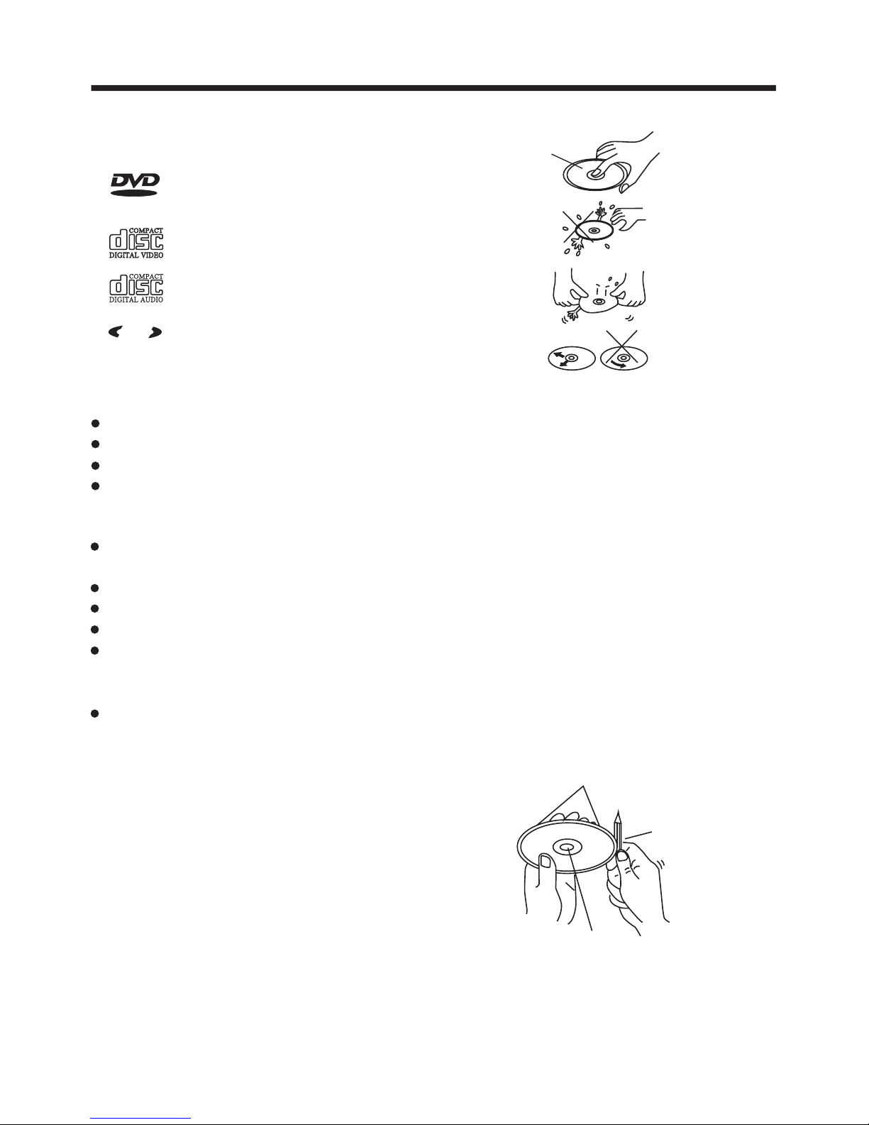
Disc formats supported by this
player
Rough spots
on
outside edge
Ball point pen
or pencil
Rough spots
on inside
edge
Disc Cleaning
Use a dry soft cloth to wipe the surface.
If the disc is quite dirty, use a soft cloth
slightly moistured with isopropyl (rubbing)
alcohol. Never use solvents such as
benzine, thinner or conventional record
cleaners as they may mar the surface of
the disc.
Handling and Cleaning
Dirt, dust, scratches and warping of
discs may prevent operation.
Do not warp discs.
A disc should always be kept in its
case when not in use to prevent from
being damaged.
Do not place discs in the following
places:
1.Direct sunlight
2.Dirty, dusty and damp areas
3.Near car heaters
4.On the seats or dashboard
Do not put stickers on discs
Avoid scratching discs.
Discs which cannot be played
with this player
DVD-ROM
DVD-R/DVD-RAM
CDV
CD-G
3
VIDEO
MPM
P
3
CD-RW
DVD
12 cm disc
(Single-sided disc only)
Video CD
12 cm disc
CD
12 cm disc
MP3
12 cm disc
Label side
up
Do not touch
the
underside
of the disc
Do not
bend
Wipe the disc from
center
toward the outside
edge
Page 4
INSTALLATION
4
Choose a mounting location where the unit will not interfere with the normal
driving function of the driver.
Before final installation of the unit, connect the wiring temporarily and make sure
all connected properly and the unit and the system work properly.
Use only the parts included with the unit to ensure proper installation. The use
unauthorized parts may cause malfunctions.
Consult with your nearest dealer if installation requires the drilling of holes or
modifications to the vehicle.
Install the unit where it does not get in the driver's way and cannot injure the
passenger if there is a sudden stop .
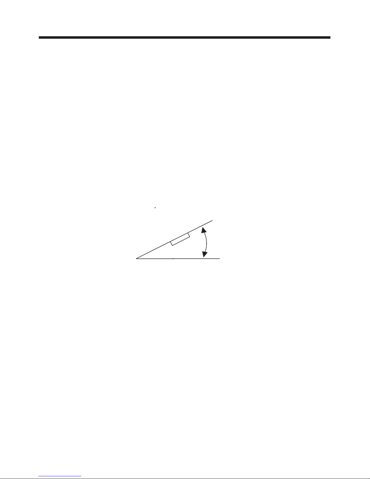
If installation angle exceeds 30 from horizontal, the unit might not give its
best performance.
Avoid installing the unit where it would be subject to high temperature, such
direct sunlight, or from hot air from the heater, or where it would be
dirt or excessive vibration.
This unit can be properly installed either from "Front" (conventional DIN
or "Rear" (DIN Rear-mount installation, utilizing threaded
the unit chassis). For details, refer to the following
illustrated installation methods.
NOTES:
DIN FRONT/REAR-MOUNT
it is
of
other
as from
subject to dust,
Front-mount)
screw holes at the sides of
30
Page 5
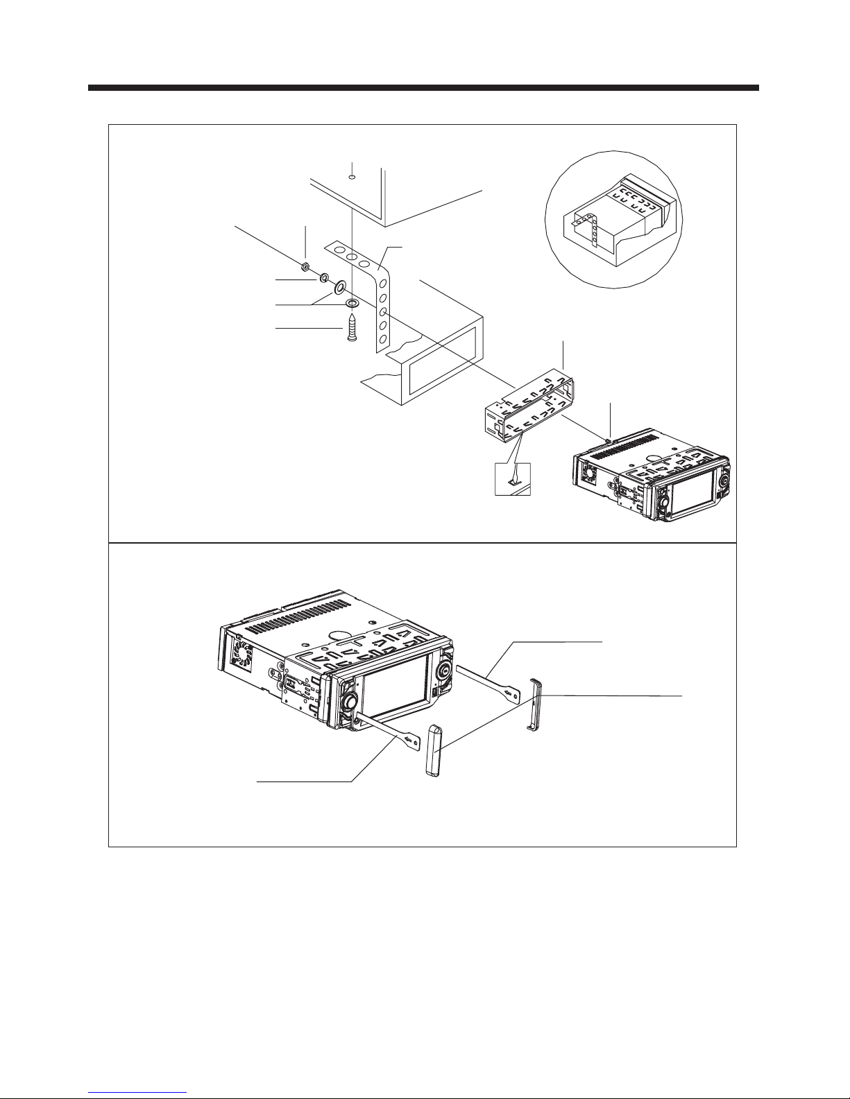
INSTALLATION
5
REMOVAL KEY
REMOVAL KEY
PLASTIC COVER
DASH BOARD
METAL MOUNTING
STRAP
HEX NUT
SPRING WASHER
PLAIN WASHER
TAPPING SCREW
CONSOLE
SLIDE BRACKET
HOUSING
HEX BOLT
To remove the unit, first remove the plastic covers from each side.
Then insert the two REMOVAL KEYS into the slots at the left and right
side of the chassis as shown in the drawing. This will release the unit from
its mounting sleeve and permit you to slide it out.
Page 6
6
INSTALLATION
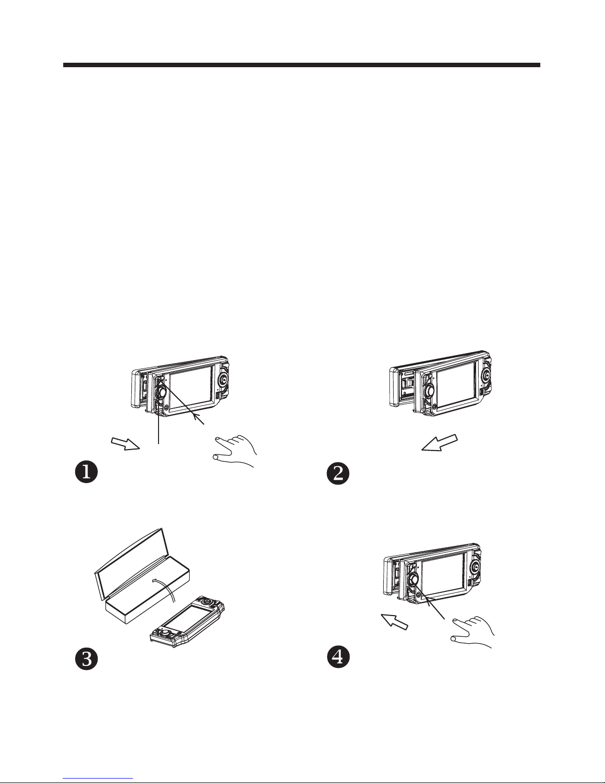
How To Remove and Install The Front Panel
When detaching or reattaching the control panel, be careful not to damage the
connectors on the back of the control panel and on the panel recess on main unit .
Detaching the Front Panel
Install the Front Panel
Before detaching the control panel, be sure to turn off the power.
1.
2.
3.
Press the PWR button (2) briefly to switch the device ON.
Press the release button in the upper left corner of the front panel.(Figure 1. )
Once the left side is released, slide it slightly to the left to disengage it and lift it off.
( Figure 2. )
Always store the panel in its protective case to avoid scratches and damage to the
connectors on the rear. (Figure 3. )
To reinstall the panel, insert the right side of the panel first, then gently press the left
side until you feel a "click.” (Figure 4. )
Page 7
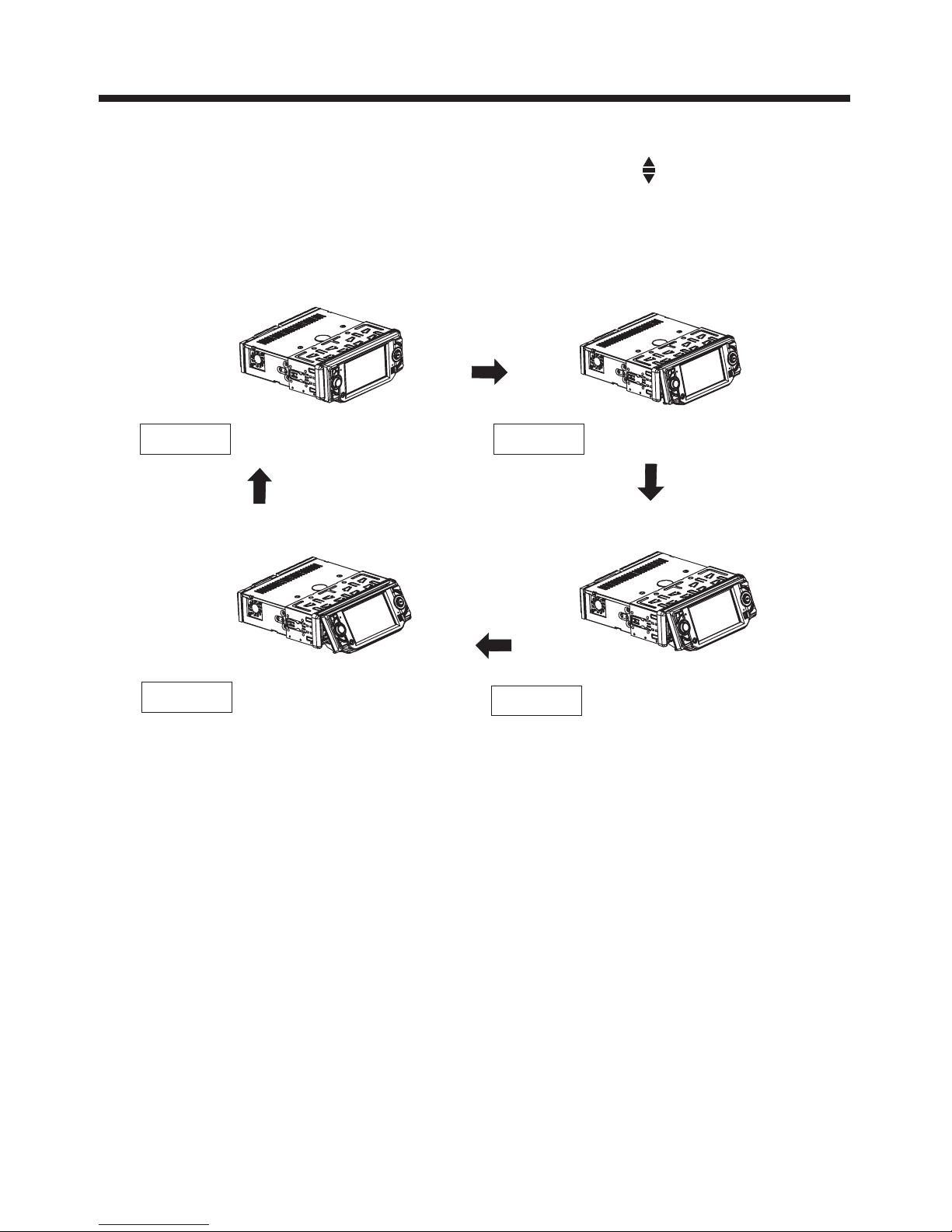
PANEL ANGLE ADJUSTMENT
7
Caution:
Never put your finger behind the control panel.
To change the viewing angle of the display, press the (angle) button
repeatedly to select the desired angle as show below:
CHANGING THE CONTROL PANEL ANGLE
Angle 3
Angle 4
Angle 1 Angle 2
Page 8
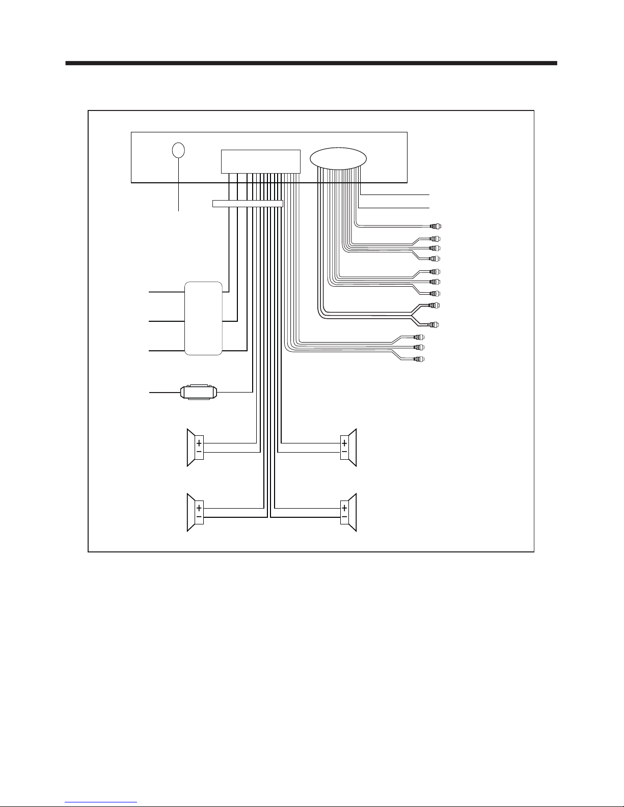
WIRING CONNECTIONS
8
Note:
The (B-) parking brake wire must be connected in order for video images to
appear on the monitor. If the wire has not been correctly connected,
the message “PARKING BRAKE” appears on the monitor.
(This wire must be connected to the (-) negative side of the parking brake system
of your vehicle. Once you engage the parking brake system, you will be allowed
to watch the video.)
VIDEO IN YELLOW
RCH IN RED
LCHINWHITE
GREY SUBWOOFER
VIDEO OUT 2 YELLOW
COAXIAL OUT BROWN
WHITE
(B+)12V
REAR CAMERA SWITCH
GREEN
YELLOW
AUX(optional)
RCA CABLE
REAR CAMERA INPUT
(B-)PARKING BRAKE
FRONT RCA WHITE L
RCH RED
LCH WHITE
FRONT RCA RED R
VIDEO OUT 1 YELLOW
REAR RCA OUTPUT
CABLE (optional)
FRONT RCA OUTPUT
CABLE
(FOR RCA LINE OUT VERSION ONLY)
GREY
GREY/BLACK
FRONT
Rch SPK.
VIOLET
VIOLET/BLACK
WHITE
WHITE/BLACK
GREEN
GREEN/BLACK
REAR
Lch SPK.
AUTO
ANTENNA
BLUE
FUSE
GROUND(B-)
MEMORY
BACK-UP(B+)
IGNITION
SWITCH(B+)
ANTENNA CONNECTOR
RED
YELLOW
BLACK
MAIN UNIT
REAR
Rch SPK.
FRONT
Lch SPK.
CHOKE
BOX
ISO CONNECTOR
Page 9

REMOTE CONTROL
9
1.CLK
2.MODE
3.STOP
4.SETUP
Press this button to view the clock time. Press again to return to normal
display mode.
Press repeatedly to cycle through the various modes:
RADIO>DISC>AUXIN.
Press once to pause playback. Press PLAY/PAUSE to resume playback.
Please note: if you press STOP twice, playback will start at the beginning
of the disc.
Press this button to open the SETUP menu.
In Radio mode, press this button to change between Mono and Stereo
reception modes (when a station is weak, sometimes switching to Mono
will improve sound quality). In Disc Playback mode, pressing this button
opens the AUDIO setup menu for making changes to the way the
soundtrack is reproduced.
In DVD Disc Playback mode, pressing this button will allow you to change
the subtitle language on discs which have this as an option. In Radio
mode, press this button to change the radio reception sensitivity in
stations are near or far.
Pressing this button will open a menu presenting you with the playback
repeat options available for that kind of disc.
Press this button to begin playback at a moment in the program you
designate. Use the number buttons to enter the data that is needed.
Press these buttons to skip ahead or back one track.
Press this button repeatedly to cycle through the various audio and video
adjustments you can make: VOLUME, BASS, TREBLE, BALANCE,
FADER, COLOR, BRIGHTNESS, CONTRAST and TINT.
Use these controls to adjust the volume level.
Use these buttons to navigate the various menus present in the product.
Press this button briefly to display the root level directory of a DVD disc.
Press and hold this button to turn on or off the SUBWOOFER output.
In Radio mode, press this button repeatedly to switch between the five
radio bands: FM1 > FM2 > FM3 > AM1 > AM2. In Disc Playback modes,
Press this button to see information about the disc currently in play.
Press to turn the unit on or off.
In Disc Playback mode, press to pause playback. Press again to start
where playback stopped. In Radio mode (when RDS mode is engaged),
press this button to make a selection within the PTY stations available.
Press this button to turn off the audio. Press again to restore the sound
to its prior volume level.
(Note: In DVD
mode, press continually the twice to skip back one)
6. SUBTITLE
LOCAL/DISTANT
7.REPEAT
8.GOTO
9. and
10.SEL
11. VOL+/VOL-
12. / / /
13.MENU
SUB WOOFER
14.BAND(OSD)
15.POWER
16.PLAY/PAUSE
17.MUTE
5.MO/ST(AUDIO)
17
15
19
13
14
7
2
6
11
18
3
16
5
20
1
21
26
9
12
10
4
8
25
23
22
24
Page 10

REMOTE CONTROL
10
Using the Remote Control
When you use the remote, be sure to be no more than six feet from the IR receiver
on the unit, and within 30º to the left or right of the IR window. Beyond these ranges,
the remote control may not communicate properly with the unit.
Preparing the Remote Control
1. Press the release catch on the battery drawer in the direction shown in the picture
below ( ) . Then with your fingertip pull the drawer out ( ).
2. Take careful note of the polarity of the battery before you remove it.
The (+) terminal must be UP as shown in the picture below ( ).
3. Insert a new battery, and push in the battery drawer until you feel a "click." ( )
Inserting the Battery
1
2
3
4
20.ANGLE MARK
BUTTON
21.EQ
23.ENTER
24. 0-9 NUMBER
BUTTONS
25.+10 BUTTON
26. RADIO PRESET BUTTONS
18.TITLE/PBC
(Playback Control
mode),
AP (Auto-Program
mode).
When playing a DVD, pressing this button will open the TITLE
menu which is recorded on the DVD. When playing a VCD disc,
press this button to create a PBC (Playback Control) menu for
the disc to assist in making playback selections. In Radio mode,
press and hold this button to start the Auto-Program mode,
during which the tuner will scan for all strong stations and assign
them to the radio preset buttons.
Press this button to adjust the screen viewing angle (see page 7).
For DVD discs which have alternate viewing angles encoded,
when you see the "angle mark" symbol advising you that these
angles are available, press this button to see them.
Press repeatedly to cycle through the different equalizer curve
presets you may wish to use for enhanced listening.
In Disc Playback mode, press for fast forward/reverse playback.
This button is used to confirm selections and settings within
many of the menus in the OSD system.
These buttons are used for numeric entry in many different
menus. In addition, in Radio Mode (when RDS is engaged),
0servesastheTAbuttonand9servesastehAFbutton.
This button is used with the other number buttons for use with
two-digit number entries.
19.
22. and
Page 11

BASIC OPERATION
11
1.REL (RELEASE)BUTTON
Press this button to release the front panel for removal.
See page 6 for removal instructions.
3.VOL+/ VOL- knob
In normal mode, this knob is used to increase or decrease the volume. It is also
used as an UP/DOWN knob when audio or video settings are being adjusted
when accessed using the SELECT button.
Tint Contrast Bright Color
Volume Bass Treble Balance Fader
4.SELECT KNOB
To access the available adjustment settings for audio and video, press this knob
repeatedly to cycle through and select them:
FM MW LW
For 3 Bands (Europe)
FM MW
For 2 Bands (Europe)
FM AM
For 2 Bands (USA)
5. BAND BUTTON
In Radio mode, press this button repeatedly (or the BAND button on the remote
control) to cycle through and select the desired radio band:
6. TA and AF FUNCTIONS (using the SELECT knob)
TA Function
In Radio mode (when RDS is enabled), briefly press the SELECT knob up in the
direction of the TA/AF markings. This will turn on the Traffic Alert system, which
automatically plays a traffic alert station when alerts are announced. When there
are no alerts, the radio returns to normal mode.
1123
16
2
17
6
7
4
11
1814
8
5
9
10
13
15
CH
X
SEL
CH 1-6
MU/PTY
2. (POWER On/Off) BUTTON
Press this button to turn the unit On or Off.
Page 12

BASIC OPERATION
12
AF Function
Press and hold the SELECT knob for more than two seconds in the direction of
the TA/AF markings to turn on the Alternate Frequency function. When is on,
the radio will continuously monitor the frequency and will switch to another one
if the signal is stronger.
Pressing and holding for a longer time will open a selection menu for setting up
the specific behaviors of the system when AF function is enabled.
7. APS, DISPLAY FUNCTIONS (using the SELECT knob)
In Radio mode, press the SELECT knob briefly down, in the direction of
the APS/DISP markings, to scan and play all the presets in radio bands in order.
If you like one of them, press the knob again to stop the scanning.
In Radio mode, press and hold the SELECT knob down, in the direction of
the APS/DISP markings, for about two seconds for the tuner to automatically
scan the current AM or FM frequency band and assign the strongest stations
found to the six preset buttons. To set up the presets for a different band,
press the BAN D button as need to move to that band, and again press and hold
the SELECT knob for about two seconds to have the tuner auto-scan and setup
the presets for that band.
In Disc Playback mode, press and hold the SELECT knob down, in the direction
of the APS/DISP markings, for about two seconds, to turn off the display image
(sound will stay on). Repeatedly press the SELECT knob to step through
the BACKGROUND COLOR options.
Scan Function
Automatic Preset Setup
Display ON/OFF Function
9. ANGLE (Screen position)
This button allows you to change the angle of the screen module in four steps.
Press this button repeatedly to cycle through the different positions.
8. MUTE PTY BUTTON
Press this button to turn off the audio. Press again to restore the volume to the
prior level. You can also disable the MUTE function by turning the VOL +/- knob .
In RDS Radio mode, press this button repeatedly to step through the different
station categories (such as NEWS, INFO, SPORTS, etc). When you have selected
the category, the radio searches for stations in that category.
10. PLAY/PAUSE, CH 1-6 (RADIO PRESET) BUTTON
In Disc Playback mode, press this button to pause playback. Press again to
resume playback.
In Radio Mode
Press this button repeatedly to preset station. With this system a total of 30
stations can be stored in the memory . Each band store up to six preset stations.
The stations might be FM1, FM2, FM3, AM1 (MW1) and AM2 (MW2)
band. The operation as below :
Page 13

BASIC OPERATION
13
Normal Playback 2x 4x 8x 16x
11.UP/DOWN BUTTONS (using the SELECT knob)
In Disc (or USB) Playback mode, briefly press the SELECT knob up or down to
skip forward or back one track. Press and hold up for more than two seconds to
begin Fast Forward (or down for Fast Reverse) mode. Press the button again
as needed, to cycle thru the range of available speeds.
In Radio mode, briefly push the SELECT knob up or down to manually tune the
radio in single steps. Press and hold for two seconds for the radio to seek the
next station automatically.
13. (EJECT) button
To insert a disc, press this button. The panel will swing downward, exposing the
slot. Insert the disc, label side facing up, until the mechanism senses its presence
and draws the disc in. The panel will automatically return to its previous position.
14. RESET button
Pressing the RESET button (with a ball point pen or similar object) is done
at these times:
a. After initial installation, when all wiring is completed.
b. If the buttons or display do not operate properly.
c. An ERROR symbol appears on the display.
12. MODE BUTTON
Use this button to select an input mode by pressing repeatedly until the proper
one is found:
AUXIN>RADIO>DISC
If you are in USB Playback mode and want to select DISC mode, press the STOP
button and then the GO TO button.
- store in memory
press and hold the desired memory location for several seconds, the current
listening station will be stored into the number location.
- retrieve a preset station
press it button repeatedly to retrieve a station which had been stored in the
memory in advance the chosen number is shown on display.
15. IR sensor
16. AUX INPUT JACK
For information about using an AUX IN audio source, please see page 15.
17. USB PORT
For information about connecting a USB device, please see page 17.
Page 14

BASIC OPERATION
14
3/INT BUTTON
In CD Playback mode, press this button to start the Intro Scan function.
The player will play the first six seconds of a track and then skip to the next and
do the same, and so on. If you hear a song you wish to continue listening to,
press the button again. (Please note: this button does not have this function
in MP3 playback mode).
REPEATALL
CHAPTER REPEAT ON TITLE REPEAT ON
DVD:
REP-ONE REP-ALL
VCD/CD/MP3:
REPEAT BUTTON
Pressing the repeat button repeatedly allows you to cycle through and select one
of the REPEAT modes available as follows:
In VCD Playback mode, press and hold this button to display the following menu:
SELECT DIGEST TYPE:
TRACK DIGEST
DISC INTERVAL
TRACK INTERVAL
Use the UP, DOWN, LEFT and RIGHT arrows on the remote to select an item,
and press ENTER to confirm.
In DVD Playback mode, press and hold this button to display the following menu:
SELECT DIGEST TYPE:
TITLE DIGEST
CHAPTER DIGEST
TITLE INTERVAL
CHAPTER INTERVAL
Use the UP, DOWN, LEFT and RIGHT arrows on the remote to select an item,
and press ENTER to confirm.
4/RANDOM BUTTON
In Disc Playback mode, press this button to begin playback of all the tracks on the
disc in RANDOM order. To return to normal playback mode, press again.
ADDITIONAL FUNCTIONS ONLY PRESENT ON REMOTE CONTROL
In VCD, CD or MP3 Playback mode, pressing this button will select and play the
first track or chapter on the disc. (Please note: this button does not have this
function in DVD mode).
1/TOP BUTTON
Page 15

BASIC OPERATION
15
MP3/WMA/JPEG DISC PLAYBACK
When you insert a disc which contains MP3, WMA or JPEG files, the different file
types are detected, and a list of the files are produced, as shown in the diagram
below.
00:56 04:07
003/112
Repeat one
Mp3
Mp3
Mp3
..............
K
P
woman
1
new
ton
The upper half of the display provides
information for the file which is highlighted
in the lower half. For example, in the screen
below, the selected track is #3 of a total
of 112 available, its total playing time
is 4:07, and the currently elapsed playing
time is 56 seconds. The presence of the
PLAY button indicates that the playback is
stopped or paused, and you can use
the UP or DOWN buttons to select it (and
press ENTER) to begin playing the song.
The lower part of the screen shows the track list and the file type, and you can use
the UP and DOWN buttons to navigate the list.
REPEAT Function
In the upper part of the screen there is also an indication of whether or not a
REPEAT function is in play, and if so, what type it is . Press the REPEAT button to
cycle through (and press ENTER to confirm) the desired program from
the following:
REPEAT ONE (repeats the same song over and over)
REPEAT ALL (plays all songs on the disc, then repeats the entire disc over and over)
SKIP AHEAD/BACK
In Playback mode, use the or buttons to skip ahead or back one item in the list.
FAST FORWARD/FAST REVERSE PLAYBACK
In Playback mode, press and hold the SELECT knob to the right or left ( towards
the UP or DOWN markings) for more than two seconds to move to FAST FORWARD
or FAST REVERSE play. You can also briefly press the UP or DOWN buttons on the
remote to accomplish this.
AUX INPUT JACK
The front panel AUX IN jack is an excellent way to bring in audio from the
headphone output jack of MP3 music players such as the iPod and other players.
1). Please connect the external device with stereo jack plug the AUX IN socket.
2). Press the MOD button to select the AUX IN connection.
3). Rotate the VOL+/- button you can change the volume level.
SCROLL CAPTION ADJUSTMENT
You can adjust your desired scroll caption , the method of the operation as follow:
a). Press and hold the SETUP button (for about 2 seconds) on the remote control,
the adjustment scroll bar will display on the screen .
b). Use the VOL+/- to select among of the “A, B, C ....X, Y, Z, and blank ”, and use
the / button on the front panel to ahead/back (proceed/cancel) , and then
press the SETUP button briefly to confirm . (Press it button longer
again to renew . )
In Radio mode:
Page 16

16
BASIC OPERATION
Tint Contrast Bright Color
Volume Bass Treble Balance Fader
VIDEO QUALITY ADJUSTMENT
In any video display mode, press the SELECT knob repeatedly to cycle through
and select the various audio and video parameters you may wish to adjust:
The video adjustments are made using a scale of 0-32.
REAR VIEW CAMERA
If you have properly installed and connected a rear-view camera, when you shift
your car into reverse gear the monitor will automatically begin displaying the view
from the camera (Please note that the image is ONLY displayed on the built-in
monitor. Connected external monitors will continue to show the current program).
BRAKE CONNECTION SAFETY FEATURE
As a safety feature, this system includes a wiring connection to the parking brake.
The system can only display a picture on the built-in monitor (which can be
distracting to the driver) when the parking brake has been applied. If you attempt
to view a video when the parking brake is OFF, no picture will be displayed, and
the warning message "PARKING BRAKE" will flash on the screen.
(Please note that this warning will only appear when the parking brake wire is
connected in the vehicle.)
MPEG4 DISC PLAYBACK
MPEG4 disc is playing as the format
of FILE . For example:
/
In stop mode , use / on the
remote control to select the item ,
then press ENTER button to confirm.
Pressing REPEAT button repeatedly can
select three kinds of repeat play mode.
REP-ONE:
Play the same song over and over again.
REPEAT ALL:
Play all songs in the current directory in sequence, over and over again.
DISC REPEAT:
Play all songs in the discover and over again.
In the playback, use or to skip an item ahead or back.
In the playback, swing the SEL knob in the direction of / button on front panel
and keep more than 2 seconds or short press on the remote control to rapid
forward/reverse.
00:56 04:07
001/001
Repeat one
..............
MAY-AUG
C14-Long-fright
Page 17

BASIC OPERATION
(USB connect line)
USB port
USB Operation
Following the diagram below, connect
your USB device to the front panel USB
port. If it is properly connected, the
device will be mounted and start
playing automatically.
TO PREVENT DAMAGE TO THE USB
DEVICE, DO NOT REMOVE OR
DISCONNECT IT DURING PLAYBACK.
It is also a good practice to remove
the USB drive during disc playback.
Important Note:
In USB Playback mode
REPEAT
REPEAT
Use the UP, DOWN, RIGHT or LEFT
buttons to navigate to and select files
to play, and press ENTER to begin
playback (or viewing, in the case of
JPEG files). To skip to the next or
last track, press the or buttons.
Press the or buttons for Fast
Forward or Fast Reverse playback.
play modes are also available
by repeatedly pushing until
the desired mode is found.
Changing From USB to DISC Playback
Modes
Changing From DISC to USB Playback
Modes
If you are in USB Playback mode and
wish to begin playback of a disc already
in the player, press the STOP button
once. Then press the GOTO button
and the player will switch to DVD/VCD/
CD/MP3 Playback mode.
If the disc present in the player is an
MP3 disc, press the STOP button once
and press the GOTO button to USB
playback.
If the disc present in the player is an
DVD or VCD or CD disc, press the
STOP button twice and press the
GOTO button to USB playback.
17
TITLE ELAPSED
TT 01/01 CH 01/38 0:02:06
d.Press OSD a fourth time:
c. Press OSD a third time:
b. Press OSD again:
TITLE REMAIN
TT 01/01 CH 01/38 3:24:36
CHAPTER ELAPSED
TT 01/01 CH 01/38 0:02:56
CHAPTER REMAIN
TT 01/01 CH 01/38 0:04:32
A.Press OSD once:
b.Press OSD a second time:
c.Press OSD a third time:
d.Press OSD a fourth time:
SINGLE ELAPSED
TRACK 01/16 00:49
SINGLE REMAIN
TRACK 01/16 02:45
TOTAL ELAPSED
TRACK 01/16 00:60
TOTAL REMAIN
TRACK 01/16 78:46
In the following example, we are looking
at the content information of a VCD,
SVCD or CD disc:
Pressing OSD for MP3 discs does not
display as much information. The
information simple switches back and
forth as follows:
SINGLE ELAPSED SINGLE REMAIN
Press the OSD button during Disc
Playback to display information about
the current disc. Pressing repeatedly
will show you different data, as shown
below. In this example, we are looking
at the contents of a DVD disc.
DVD example:
a. Press OSD once:
On-Screen Display Function
Page 18

BASIC OPERATION
18
MONO LEFT MONO RIGHT
STEREO
MIXED MONO
AUDIO BUTTON
Multiple Audio Soundtrack Languages
on DVD discs:
Some DVD discs offer a choice of
audio soundtrack languages.
For such discs, pressing AUDIO during
playback will show you the available
languages and how to change the
language.
Sound Settings for CD and VCD discs
Pressing AUDIO during VCD or CD
playback permits you to change the
audio mode as follows:
TITLE/PBC (Playback Control
Mode) BUTTON
For DVD discs, pressing the TITLE
button brings up the TITLE MENU
which has been recorded on the disc.
For VCD discs, pressing this button
will turn on the PBC (Playback Control)
mode. In this mode, the player will
create a directory of the files on the
disc from which you can select and
confirm items you wish to play.
Press it again to turn off PBC mode.
SUBTITLE BUTTON
Multiple Subtitle Languages on DVD
discs:
Some DVD discs offer a choice of
subtitle languages. For such discs,
pressing SUBTITLE during playback
will show you the available languages
and how to change the language.
ANGLE BUTTON
Some DVD disc producers include
scenes which offer additional viewing
angles.
If a DVD has these, when those scenes
appear an ANGLE MARK symbol will
appear on the screen. If you wish to
see the alternate viewing angles at
that time, press the ANGLE button.
Page 19

SETUP
19
Video
Material
Normal
Pan Scan
TV Screen
Letter-box
Wide(16:9)
4:3
Set TV Display Mode
-----General setup page----
Angle Mark
Last Memory
TV Display
Spdif Output
OSD Lang
Captions
Normal/PS
Normal/LB
Wide
Screen Saver
DOLBY
ABOUT SETUP MENUS
Go To General Setup Page
-----General setup page----
Angle Mark
Last Memory
TV Display
Screen Saver
SPDIF Output
OSD Lang
Captions
LB
ON
ENG
ON
ON
ON
SPDIF/RAW
DOLBY
DOLBY
()1 ()2 ()3 ()4
(1). GENERAL SETUP
(2). SPEAKER SETUP
(3). DOLBY DIGITAL SETUP
(4). PREFERENCES SETUP
Use the LEFT or RIGHT arrow button
to select the desired setup menu and
press ENTER to confirm.
In the following description, we begin
with the GENERAL SETUP menu.
When you press SETUP on the remote
control, the SETUP screen will be
displayed. At the top of the screen are
four icons, representing:
Press button on the remote
control to display the SETUP menu ,
Select the preferred item by using the
/ / / buttons, and press the
ENTER button to confirm.
SETUP
Overview Of The Main Menu
The GENERAL SETUP menu includes
settings adjustment options for the
following:
TV DISPLAY: These settings are used
to adjust the TV image aspect ratio to
match the connected TV screen. While
most TV programs are produced in 4:3
format, most DVDs and other programs
are not.
For those programs, viewed on a 4:3 TV,
you can choose either Normal/PS
(Pan and Scan) or Normal/LB
(Letterbox), depending on your taste.
Normal P/S will cut off the right and left
sides of the program, but will display it
at full height. Normal/LB will reduce the
image size so that the full width fits the
screen, leaving blank black bars at the
top and bottom.
When you are connected to a widescreen
monitor, always choose the Widescreen
setting. If not, the image will not fit the
screen properly.
Page 20

3.OSD LANGUAGE SETUP
Select the preferred OSD language using
the / buttons.
20
5.CAPTIONS SETUP
Activate the CAPTIONS feature by
selecting ON.
2.ANGLE MARK DISPLAY SETUP
If it is set to ON, when a DVD disc which
has been produced with alternate
viewing angles is played, (the “angle
mark”) will appear on the screen. if it is
set to OFF, the mark will not appear.
4.SPDIF OUTPUT
This is to activate the audio output from
SPDIF OFF mode to SPDIF/RAW mode
to SPDIF/PCM mode.
Set Angle Mark
-----General setup page----
Angle Mark
Last Memory
TV Display
SPDIF Output
OSD Lang
Captions
ON
OFF
Screen Saver
DOLBY
Setup SPDIF
-----General setup page----
Angle Mark
Last Memory
TV Display
SPDIF Output
OSD Lang
Captions
SPDIF OFF
SPDIF/RAW
SPDIF/PCM
Screen Saver
DOLBY
-----General setup page----
Angle Mark
Last Memory
TV Display
SPDIF Output
OSD Lang
Captions
Set OSD Language
Spanish
German
French
English
Portuguese
Italian
Screen Saver
DOLBY
Closed Caption
-----General setup page----
Angle Mark
Last Memory
TV Display
SPDIF Output
Captions
ON
OFF
Screen Saver
OSD Lang
DOLBY
SETUP
Page 21

21
SPEAKER SETUP
DOLBY DIGITAL SETUP
DYNAMIC RANGE CONTROL
Select DRC and adjust the dynamic range
of a Dolby Digital encoded program. There
are 8 steps between full compression and
off compression.
Screen Saver
-----General setup page----
Angle Mark
Last Memory
TV Display
SPDIF Output
OSD Lang
Captions
ON
OFF
Screen Saver
DOLBY
DOWNMIX
LT/RT
STEREO
Set Downmix Mode
-----Speaker Setup Page----
DOLBY
Set Last Memory State
-----General setup page----
Angle Mark
Last Memory
TV Display
SPDIF Output
OSD Lang
Captions
ON
OFF
Screen Saver
DOLBY
Set DRC OFF
FULL
6/8
4/8
OFF
2/8
-----Dolby Digital Setup----
DYNAMIC
DOLBY
SETUP
6.SCREENSAVER SETUP
If the screen displays a static image for too
long, some "burn-in" may occur, leaving a
permanent trace of the image behind. To avoid
this, turn ON the SCREENSAVER item. After
a short period of inactivity on the monitor, the
unit will substitute a moving image to avoid
burn-in.
LAST POSITION MEMORY SETUP
This player is capable of remembering the
moment in your disc playback you were at
when you turn the unit off. If LAST MEMORY
is turned ON, when you turn the player back
on again, it will resume playback at that
memorized location in the program.
DOLBY DOWNMIX
Many DVD discs are recorded using a surround sound recording technology called Dolby
AC3 5.1. When such a disc is played in a normal 2- or 4-channel playback unit like this one,
the surround sound must be "downmixed" to
stereo. In this case, choose "stereo," unless
the output from this unit is connected to a
mobile Dolby surround sound system. In that
case, choose LT/RT.
Page 22

22
PREFERENCES SETUP
2.AUDIO LANGUAGE SETUP
Select the preferred AUDIO soundtrack
language using the cursor buttons.
3.SUBTITLE LANGUAGE SETUP
Select the preferred SUBTITLE
language using the cursor buttons.
4.DISC MENU LANGUAGE SETUP
Select the preferred DISC MENU
language using the cursor buttons.
Set TV standard
-----Preference Page----
Audio
Default
TV Type
Password
Disc Menu
Subtitle
Parental
AUTO
NTSC
PAL
DOLBY
Audio
Default
TV Type
Password
Disc Menu
Subtitle
Parental
-----Preference Page----
Spanish
German
French
English
Portuguese
Italian
Preferred Subtitle Language
OFF
DOLBY
Audio
Default
TV Type
Password
Disc Menu
Subtitle
Parental
-----Preference Page----
Spanish
German
French
English
Portuguese
Italian
Preferred Menu Language
DOLBY
SETUP
1. TV TYPE SETUP
This player is capable of playing discs
recorded in either PAL or NTSC formats.
Make the selection based on whether you
are connecting the unit to a PAL TV or an
NTSC TV. You can also set the unit to
AUTO (autoselect). The disadvantage to
autoselect is that each time you turn the
unit on it checks to see what kind of
monitor is connected, which causes a
small delay and some flickering of the
display image which you may find
unpleasant.
Audio
Default
TV Type
Password
Disc Menu
Subtitle
Parental
-----Preference Page----
Spanish
German
French
English
Portuguese
Italian
Preferred Audio Language
DOLBY
Page 23

23
5.PARENTAL
Select suitable parental guidance with
the cursor buttons and confirm it by
pressing the ENTER button.
7.DEFAULTS
Selecting the DEFAULT item and
confirming RESET will return ALL
personal settings you have made,
including radio and TV presets, to the
factory default settings.
Audio
Default
TV Type
Password
Disc Menu
Subtitle
Parental
-----Preference Page----
Set Parental Control
1KID SAF
2G
3PG
4PG13
5PGR
6R
OFF
7NC 17
8 ADULT
DOLBY
Change Password
Audio
Default
TV Type
Password
Disc Menu
Subtitle
Parental
CHANGE
-----Preference Page----
DOLBY
Audio
Default
TV Type
Password
Disc Menu
Subtitle
Parental
-----Preference Page----
Load Fcatory Setting
RESET
DOLBY
DEFAULTS TABLE
GENERAL SETUP
SPEAKER SETUP
DOLBY DIGITAL
PREFERENCES
TV DISPLAY
ANGLE MARK
SPDIF OUPUT
OSD LANGUAGE
CAPTIONS
LAST MEMORY
DOWNMIX
DYNAMIC
TV TYPE
AUDIO
SUBTITLE
DISC MENU
PARENTAL
PASSWORD
NORMAL/LB
ON
ON
ENGLISH
ON
STEREO
AUTO
ENGLISH
OFF
ENGLISH
8 ADULT
1379
ON
OFF
SCR SAVER
SPDIF/RAM
SETUP
6.PASSWORD SELECTION
The password must be used to make changes
to the Parental Control menu above. The
factory default password is 1379. To change
this password, press change. You will be
asked for the current password. Once you
have entered it, you have the opportunity to
change it. Then, when you enter the Parental
Control menu, you will be required to use this
new password in order to make any changes.
Page 24

Supply Voltage: 12V DC (11V-15V)
Current Consumption: Less than10 A
Signal System: Compositive video 1.0Vp-p 75
Discs Played: (1) DVD-VIDEO Disc
5"(12 cm) single-sided, single-layer
5"(12 cm) single-sided, double-layer
(2) Compact Disc (CD-DA, VIDEO CD)
5"(12cm) disc
Audio Signal Output: 2CH and 4CH line out
Characteristics: (1) Frequency Response 20 Hz - 20 KHz
(2) S/N Ratio 90 dB (JIS)
(3) Wow and Flutter Below measurable limits
For 3 Bands For 2 Bands For 2 Bands
(Europe) (Europe) (U.S.A.)
FM FM FM
Frequency Coverage: 87.5 to108 MHz 87.5 to108 MHz 87.5 to107.9 MHz
Intermediate Frequency: 10.7 MHz 10.7 M z 10.7 MHz
Sensitivity (S/N = 30 dB): 15
MW MW AM
Frequency Coverage: 522 to1620 KHz 522 to1620 KHz 530 to1710 Khz
450 K z 450 KHz 450 KHz
Sensitivity (S/N = 20 dB): 40 dBu 40 dBu 40 dBu
LW (Optional)
Frequency Coverage: 144 to290 Khz
450 KHz
Sensitivity (S/N = 20 dB): 45 dBu
H
dBu 15 dBu 15dBu
Intermediate Frequency: H
Intermediate Frequency:
NOTE: Specifications are subject to change without notice.
SPECIFICATION
24
Color System:
Monitor Screen Size:
Number of Pixels:
4.3 Inch Wide Screen
1152 X 234 pixels
Page 25

Before going through the check list, check wiring connection. If any of the problems
persist after check list has been made, consult your nearest service dealer.
TROUBLE SHOOTING
25
The disc has been
inserted upside down.
Remove and re-insert the front panel,
making sure it is properly seated.
Clean the connector on the back of the
rear panel with a clean cotton swab
and isopropyl (rubbing) alcohol. If the
above does not resolve the problem,
press the RESET button.
The car ignition switch is
not on.
If the power supply is properly
connected to the car accessory
terminal,switch the ignition key
to
"ACC".
The fuse is blown.
Replace the fuse.
There is already a disc in
the player.
Remove the disc before putting
in another.
Insert the disc with the label
facing upward.
Be sure to insert discs
label side UP.
Clean the disc or try to play a
new one.
Temperature inside the
car is too high.
Permit the vehicle interior to cool
down before using the player.
The built-in microcomputer is not operating
properly due to noise.
The antenna cable is not
connected.
Insert the antenna cable firmly
The signals are too weak.
Select a station manually
SYMPTOM POSSIBLE CAUSE SOLUTION
The color system is
set incorrectly.
No screen image
appears.
The unit is not connected
to the parking brake
detection switch.
Properly connect the parking
brake wire to the unit.
The parking brake is not
engaged.
For safety reasons no television or
video images are displayed while
the vehicle is moving.
Engaging the parking brake will
enable images to be displayed.
Buttons and/or
display do not work
properly, or not
at all.
The radio does
not work.
Disc can not be
loaded or ejected
No power
The picture color
is poor or faint.
The disc format and the TV
formats are mismatched
(conflict of NTSC and PAL).
Check and make sure the disc
format and TV format are the
same.
JPEG disc can
not be played
back.
No JPEG files are
recorded on the disc.
JPEG files are not
recorded in a compliant
formant.
Re-record the disc in a compliant
application. You may need to
read the instructions for your
disc recording software.
Use a disc with JPEG files.
The screen image
is black and white
when you expect
color.
Be sure the proper TV system
settings are selected and color
adjustments are appropriate.
 Loading...