

Page 1
Owner’s Manual
Thank you, and congratulations on your choice of the BOSS BR-1600CD Digital Recording Studio.
Before using this unit, carefully read the sections entitled: “USING THE UNIT SAFELY” and “IMPORTANT
NOTES” (Owner’s manual p. 2–3; p. 4–5). These sections provide important information concerning the proper
operation of the unit. Additionally, in order to feel assured that you have gained a good grasp of every feature
provided by your new unit, Basic Operation and Owner’s manual should be read in its entirety.
The manuals should be saved and kept on hand as a convenient reference.
■
How to use this manual
The BR-1600CD Owner’s manual consists of two volumes “
“
Basic Operation
” explains the sequence of turning on this unit, recording, playback, mixing down and
Basic Operation
” and “
Owner’s Manual
.”
making an original Audio CD. To use the BR-1600CD, please read this book first.
“
Owner’s Manual
” covers the functions which are not mentioned in “Basic Operation.” Please read it for
finer settings and more sophisticated use of the BR-1600CD.
■
Printing conventions in this manual
• Text or numerals enclosed in square brackets [ ] indicate buttons.
[PLAY]
[CURSOR]
• Reference such as (p. **) indicate pages in this manual to which you can refer.
PLAY button
CURSOR button
Advanced
Use
Section 2
Effects
Using
Section 3
Rhythm
Using
CD-R/RW Drive
Section 4
Using the
Section 5
Using
MIDI
Copyright © 2003 BOSS CORPORATION
All rights reserved. No part of this publication may be reproduced in any form without the written permission of BOSS CORPORATION.
Section 6
Using
USB
Convenient
Functions
Section 7
Other
AppendicesSection 1
Page 2
USING THE UNIT SAFELY
Used for instructions intended to alert
the user to the risk of death or severe
injury should the unit be used
improperly.
Used for instructions intended to alert
the user to the risk of injury or material
damage should the unit be used
improperly.
* Material damage refers to damage or
other adverse effects caused with
respect to the home and all its
furnishings, as well to domestic
animals or pets.
001
• Before using this unit, make sure to read the
instructions below, and the Owner’s Manual.
...........................................................................................................
002c
• Do not open (or modify in any way) the unit or its
AC adaptor.
...........................................................................................................
003
• Do not attempt to repair the unit, or replace parts
within it (except when this manual provides
specific instructions directing you to do so). Refer
all servicing to your retailer, the nearest Roland
Service Center, or an authorized Roland
distributor, as listed on the “Information” page.
...........................................................................................................
004
• Never use or store the unit in places that are:
• Subject to temperature extremes (e.g., direct
sunlight in an enclosed vehicle, near a heating
duct, on top of heat-generating equipment); or
are
• Damp (e.g., baths, washrooms, on wet floors);
or are
• Humid; or are
• Exposed to rain; or are
• Dusty; or are
• Subject to high levels of vibration.
...........................................................................................................
007
• Make sure you always have the unit placed so it is
level and sure to remain stable. Never place it on
stands that could wobble, or on inclined surfaces.
...........................................................................................................
The symbol alerts the user to important instructions
or warnings.The specific meaning of the symbol is
determined by the design contained within the
triangle. In the case of the symbol at left, it is used for
general cautions, warnings, or alerts to danger.
The symbol alerts the user to items that must never
be carried out (are forbidden). The specific thing that
must not be done is indicated by the design contained
within the circle. In the case of the symbol at left, it
means that the unit must never be disassembled.
The ● symbol alerts the user to things that must be
carried out. The specific thing that must be done is
indicated by the design contained within the circle. In
the case of the symbol at left, it means that the powercord plug must be unplugged from the outlet.
008c
• Be sure to use only the AC adaptor supplied with
the unit. Also, make sure the line voltage at the
installation matches the input voltage specified on
the AC adaptor’s body. Other AC adaptors may
use a different polarity, or be designed for a
different voltage, so their use could result in
damage, malfunction, or electric shock.
..........................................................................................................
008e
• Use only the attached power-supply cord. Also,
the supplied power cord must not be used with
any other device.
..........................................................................................................
009
• Do not excessively twist or bend the power cord,
nor place heavy objects on it. Doing so can
damage the cord, producing severed elements and
short circuits. Damaged cords are fire and shock
hazards!
..........................................................................................................
010
• This unit, either alone or in combination with an
amplifier and headphones or speakers, may be
capable of producing sound levels that could
cause permanent hearing loss. Do not operate for
a long period of time at a high volume level, or at
a level that is uncomfortable. If you experience
any hearing loss or ringing in the ears, you should
immediately stop using the unit, and consult an
audiologist.
..........................................................................................................
011
• Do not allow any objects (e.g., flammable material,
coins, pins); or liquids of any kind (water, soft
drinks, etc.) to penetrate the unit.
2
..........................................................................................................
Page 3
012b
• Immediately turn the power off, remove the AC
adaptor from the outlet, and request servicing by
your retailer, the nearest Roland Service Center, or
an authorized Roland distributor, as listed on the
“Information” page when:
• The AC adaptor, the power-supply cord, or the
plug has been damaged; or
• If smoke or unusual odor occurs
• Objects have fallen into, or liquid has been
spilled onto the unit; or
• The unit has been exposed to rain (or otherwise
has become wet); or
• The unit does not appear to operate normally or
exhibits a marked change in performance.
..........................................................................................................
013
• In households with small children, an adult
should provide supervision until the child is
capable of following all the rules essential for the
safe operation of the unit.
..........................................................................................................
014
• Protect the unit from strong impact.
(Do not drop it!)
..........................................................................................................
015
• Do not force the unit’s power-supply cord to share
an outlet with an unreasonable number of other
devices. Be especially careful when using
extension cords—the total power used by all
devices you have connected to the extension
cord’s outlet must never exceed the power rating
(watts/amperes) for the extension cord. Excessive
loads can cause the insulation on the cord to heat
up and eventually melt through.
..........................................................................................................
016
• Before using the unit in a foreign country, consult
with your retailer, the nearest Roland Service
Center, or an authorized Roland distributor, as
listed on the “Information” sheet.
..........................................................................................................
023
• DO NOT play a CD-ROM disc on a conventional
audio CD player. The resulting sound may be of a
level that could cause permanent hearing loss.
Damage to speakers or other system components
may result.
..........................................................................................................
101b
• The unit and the AC adaptor should be located so
their location or position does not interfere with
their proper ventilation.
..........................................................................................................
102c
• Always grasp only the plug on the AC adaptor
cord when plugging into, or unplugging from, an
outlet or this unit.
..........................................................................................................
103b
• At regular intervals, you should unplug the AC
adaptor and clean it by using a dry cloth to wipe
all dust and other accumulations away from its
prongs. Also, disconnect the power plug from the
power outlet whenever the unit is to remain
unused for an extended period of time. Any
accumulation of dust between the power plug and
the power outlet can result in poor insulation and
lead to fire.
..........................................................................................................
104
• Try to prevent cords and cables from becoming
entangled. Also, all cords and cables should be
placed so they are out of the reach of children.
..........................................................................................................
106
• Never climb on top of, nor place heavy objects on
the unit.
..........................................................................................................
107c
• Never handle the AC adaptor or its plugs with
wet hands when plugging into, or unplugging
from, an outlet or this unit.
..........................................................................................................
108b
• Before moving the unit, disconnect the AC
adaptor and all cords coming from external
devices.
..........................................................................................................
109b
• Before cleaning the unit, turn off the power and
unplug the AC adaptor from the outlet.
..........................................................................................................
110b
• Whenever you suspect the possibility of lightning
in your area, disconnect the AC adaptor from the
outlet.
..........................................................................................................
118
• Should you remove the ground terminal, make
sure to put it in a safe place out of children's reach,
so there is no chance of it being swallowed
accidentally.
..........................................................................................................
120
• Always turn the phantom power off when
connecting any device other than condenser
microphones that require phantom power. You
risk causing damage if you mistakenly supply
phantom power to dynamic microphones, audio
playback devices, or other devices that don't
require such power. Be sure to check the specifications of any microphone you intend to use by
referring to the manual that came with it.
(This instrument’s phantom power: +48 V DC, 7 mA Max)
..........................................................................................................
3
Page 4

IMPORTANT NOTES
291a
In addition to the items listed under “USING THE UNIT SAFELY” on page 2–3, please read and observe the following:
Power Supply
301
• Do not connect this unit to same electrical outlet that is
being used by an electrical appliance that is controlled by
an inverter (such as a refrigerator, washing machine,
microwave oven, or air conditioner), or that contains a
motor. Depending on the way in which the electrical
appliance is used, power supply noise may cause this unit
to malfunction or may produce audible noise. If it is not
practical to use a separate electrical outlet, connect a
power supply noise filter between this unit and the
electrical outlet.
302
• The AC adaptor will begin to generate heat after long
hours of consecutive use. This is normal, and is not a
cause for concern.
307
• Before connecting this unit to other devices, turn off the
power to all units. This will help prevent malfunctions
and/or damage to speakers or other devices.
Placement
351
• Using the unit near power amplifiers (or other equipment
containing large power transformers) may induce hum. To
alleviate the problem, change the orientation of this unit; or
move it farther away from the source of interference.
352a
• This device may interfere with radio and television
reception. Do not use this device in the vicinity of such
receivers.
352b
• Noise may be produced if wireless communications
devices, such as cell phones, are operated in the vicinity of
this unit. Such noise could occur when receiving or initiating a call, or while conversing. Should you experience
such problems, you should relocate such wireless devices
so they are at a greater distance from this unit, or switch
them off.
353
• Observe the following when using the unit’s floppy disk
drive. For further details, refer to “Before Using CD-R/
RW Discs” (p. 7).
• Do not place the unit near devices that produce a
strong magnetic field (e.g., loudspeakers).
• Install the unit on a solid, level surface.
• Do not move the unit or subject it to vibration while
the drive is operating.
354a
• Do not expose the unit to direct sunlight, place it near
devices that radiate heat, leave it inside an enclosed
vehicle, or otherwise subject it to temperature extremes.
Excessive heat can deform or discolor the unit.
355b
• When moved from one location to another where the
temperature and/or humidity is very different, water
droplets (condensation) may form inside the unit. Damage
or malfunction may result if you attempt to use the unit in
this condition. Therefore, before using the unit, you must
allow it to stand for several hours, until the condensation
has completely evaporated.
Maintenance
401a
• For everyday cleaning wipe the unit with a soft, dry cloth
or one that has been slightly dampened with water. To
remove stubborn dirt, use a cloth impregnated with a
mild, non-abrasive detergent. Afterwards, be sure to wipe
the unit thoroughly with a soft, dry cloth.
402
• Never use benzine, thinners, alcohol or solvents of any
kind, to avoid the possibility of discoloration and/or
deformation.
Repairs and Data
452
• Please be aware that all data contained in the unit’s
memory may be lost when the unit is sent for repairs.
Important data should always be backed up on a storage
device (
via USB
During repairs, due care is taken to avoid the loss of data.
However, in certain cases (such as when circuitry related
to memory itself is out of order), we regret that it may not
be possible to restore the data, and Roland assumes no
liability concerning such loss of data.
e.g., CD-R/RW disk or external computer connected
), or written down on paper (when possible).
Additional Precautions
551
• Please be aware that the contents of memory can be
irretrievably lost as a result of a malfunction, or the improper
operation of the unit. To protect yourself against the risk of
loosing important data, we recommend that you periodically
save a backup copy of important data you have stored in the
unit’s memory on a storage device (e.g., CD-R/RW disk or
external computer connected via USB).
552
• Unfortunately, it may be impossible to restore the contents
of data that was stored hard disk once it has been lost.
Roland Corporation assumes no liability concerning such
loss of data.
553
• Use a reasonable amount of care when using the unit’s
buttons, sliders, or other controls; and when using its jacks
and connectors. Rough handling can lead to malfunctions.
554
• Never strike or apply strong pressure to the display.
556
• When connecting / disconnecting all cables, grasp the
connector itself—never pull on the cable. This way you
will avoid causing shorts, or damage to the cable’s
internal elements.
558a
• To avoid disturbing your neighbors, try to keep the unit’s
volume at reasonable levels. You may prefer to use
headphones, so you do not need to be concerned about
those around you (especially when it is late at night).
559a
• When you need to transport the unit, package it in the box
(including padding) that it came in, if possible. Otherwise,
you will need to use equivalent packaging materials.
4
Page 5

IMPORTANT NOTES
561
• Use only the specified expression pedal (EV-5, FV-500L, or
FV-500H; sold separately). By connecting any other
expression pedals, you risk causing malfunction and/or
damage to the unit.
562
• Use a cable from Roland to make the connection. If using
some other make of connection cable, please note the
following precautions.
• Some connection cables contain resistors. Do not use
cables that incorporate resistors for connecting to this
unit. The use of such cables can cause the sound level
to be extremely low, or impossible to hear. For information on cable specifications, contact the manufacturer of the cable.
982
• No data for the music that is played will be output from
MIDI OUT.
Handling CD-ROMs
801
• Avoid touching or scratching the shiny underside
(encoded surface) of the disc. Damaged or dirty CD-ROM
discs may not be read properly. Keep your discs clean
using a commercially available CD cleaner.
Copyright
851
• Unauthorized recording, distribution, sale, lending, public
performance, broadcasting, or the like, in whole or in part,
of a work (musical composition, video, broadcast, public
performance, or the like) whose copyright is held by a
third party is prohibited by law.
852a
• When exchanging audio signals through a digital
connection with an external instrument, this unit can
perform recording without being subject to the restrictions
of the Serial Copy Management System (SCMS). This is
because the unit is intended solely for musical production,
and is designed not to be subject to restrictions as long as
it is used to record works (such as your own compositions) that do not infringe on the copyrights of others.
(SCMS is a feature that prohibits second-generation and
later copying through a digital connection. It is built into
MD recorders and other consumer digital-audio
equipment as a copyright-protection feature.)
853
• Do not use this unit for purposes that could infringe on a
copyright held by a third party. We assume no responsibility whatsoever with regard to any infringements of
third-party copyrights arising through your use of this
unit.
About the License Agreement
• The BR-1600CD and its CD-R/RW capability are designed
to allow you to reproduce material to which you have
copyright, or material which the copyright owner has
granted you permission to copy. Accordingly, reproduction of Music CD or other copyrighted material
without permission of the copyright owner avoiding
technical prohibiting features of second-generation and
later copying like SCMS or others constitutes copyright
infringement and may incur penalties even in case such
reproduction is for your own personal use and enjoyment
(private use). Consult a copyright specialist or special
publications for more detailed information on obtaining
such permission from copyright holders.
Disclaimer of liability
• BOSS/Roland will take no responsibility for any “direct
damages,” “consequential damages,” or “any other
damages” which may result from your use of the BR1600CD. These damages may include but are not limited
to the following events which can occur when using the
BR-1600CD.
• Any loss of profit that may occur to you
• Permanent loss of your music or data
• Inability to continue using the BR-1600CD itself or a
connected device
204
The explanations in this manual include illustrations
that depict what should typically be shown by the
display. Note, however, that your unit may incorporate a newer, enhanced version of the system (e.g.,
includes newer sounds), so what you actually see in
the display may not always match what appears in
the manual.
...........................................................................................................
204
* Microsoft and Windows are registered trademarks of
Microsoft Corporation.
206e
* The screen shots in this document are used in compliance
with the guidelines of the Microsoft Corporation.
206j
* Windows® is known officially as: “Microsoft®
Windows® operating system.”
207
* Apple and Macintosh are registered trademark of Apple
Inc.
209
* Mac OS is a trademark of Apple Inc.
220
* All product names mentioned in this document are trade-
marks or registered trademarks of their respective owners.
...........................................................................................................
5
Page 6

Precautions Regarding the Hard Disk
The BR-1600CD contains an internal hard disk. This device is of an extremely high-precision design, and it can be easily damaged
if not used and handled correctly. To ensure that the hard disk is being handled properly, you must adhere to the following:
Important Performance and Image Data
Once a hard disk fails to function normally, all data that has been stored on it could be destroyed.
●
All hard disks eventually wear out. Individual differences among hard disks and the conditions under which they are used
have a considerable effect on a hard disk's lifespan. Some devices can be used continuously for many years, while in rare
cases, others break down after a period of several months. We recommend that you consider the hard disk not as a permanent
storage site, but as a place to store data temporarily. We also recommend that you back up important performance and image
data onto the external media that is supported by your device.
For instructions on how to make such backups, refer to “Storing of songs and other hard-disk data to CD-R/RW discs (Backup)” (p. 204).
Note that Roland assumes no liability whatsoever, including monetary compensation, for the loss of any recorded content in
the event of the malfunction of, or physical damage to the hard disk, or for any direct or incidental damages resulting from
the loss of such data.
Precautions Regarding Setup and Use
Certain hard disk setup procedures and usage conditions may result in the corruption of recorded data, malfunctioning, or
physical damage to the disk, so be sure to observe the following precautions.
●
Do not subject the hard disk to vibration or shock, especially while the unit is in operation. Failure to observe this precaution
can result in the hard disk being permanently damaged.
Conditions to be avoided:
• Lifting or moving the BR-1600CD while the power is turned on.
• Transporting the BR-1600CD unprotected in an automobile trunk.
• Knocking the BR-1600CD against table edges when it is being moved.
• Positioning the BR-1600CD close to drums during performances.
• Positioning the BR-1600CD close to amplifiers for guitars and other musical instruments during performances.
●
Do not set up the unit in any location where it may be affected by vibration from external sources, or on any surface that is
not stable and level.
●
If the device includes a cooling fan, ensure that the fan and the side panel air vents remain unobstructed.
●
Do not block the ventilation holes provided in the case as this can result in the temperature inside the BR-1600CD rising, and
this will drastically reduce the hard disk's lifespan.
●
Do not use the unit in conditions of high temperature and humidity or in any location subject to rapid temperature changes.
●
Do not unplug the power cord or switch off any circuit breakers in the circuit to which the unit is connected while the power is turned on.
●
Do not move the unit while the power is turned on or immediately after turning off the power. When transporting the unit,
first turn off the power and confirm that the display screen has gone off, disconnect the power plug, then wait at least two
minutes before moving the device.
●
When you need to transport the unit, package it in the box (including padding) that it came in, if possible. Otherwise, you will
need to use equivalent packaging materials.
Emergency Procedures
* The following procedures are to be used as emergency measures only, and are not recommended for normal operation.
If the device fails to respond to operational commands or does not complete operations, turn off the power. If the power does not
shut off following normal shutdown procedures (Basic Operation; p. 9), disconnect the power plug.
If the unit does not operate normally when the power is turned on again, it may mean that the hard disk has been damaged. In
such instances, consult your dealer or the nearest Roland Service Center. Note, however, that it may not be possible to recover any
data from the hard disk once it has been lost.
In addition, even if the hard disk appears to be operating correctly, carry out a Surface Scan (p. 270) to confirm that it has not been damaged.
6
Page 7

Before Using CD-R/RW Discs
Two different types of recordable disc can be used with the
BR-1600CD—namely, CD-R discs and CD-RW discs.
What is a CD-R disc?
CD-R (Compact Disc Recordable) is a CD to which data can
be written. It is not possible to erase or move the data that
has been written.
This type of disc should be used to create audio CDs that will
be played on standard CD players. Playback of CD-RW discs
will not be possible on this type of equipment. In addition,
even if you have created an audio CD using a CD-R disc,
playback will only be possible on players that support the
playback of recordable discs.
What is a CD-RW disc?
CD-RW (Compact Disc ReWritable) is a CD that can be
written and erased. As a result, this type of recordable disc
can be used again and again.
While you can create audio CDs using CD-RW discs, it will
not be possible to play these CDs on a standard CD player.
(You will, however, be able to play these discs using the BR-
1600CD's CD-R/RW drive.)
●
To avoid the risk of malfunction and/or damage, insert
only CD-R/RW discs into the disc drive. Never insert
any other type of disc. Avoid getting paper clips, coins,
or any other foreign objects inside the drive.
●
Do not touch the lens.
●
When the lens is dirty, clean the lens with a commercial
lens blower.
●
If a write error occurs, carry out cleaning using a
commercially available CD-RW drive lens cleaner.
* Note that some commercially available cleaners are intended
for CD-R drives, while others are intended for CD-RW drives.
Be sure to select a cleaner for CD-RW drives.
* Never use commercially available cleaner intended for
standard CD players. This type of cleaner cannot be used to
clean the BR-1600CD's write lens.
* Even if the recommended type of CD-R/RW disc is used in a
perfectly normal CD-R/RW drive, the possibility of write
errors cannot be completely eliminated. Please be aware that
this type of problem can still occur as a result of variations in
CD-R/RW drives and CD-R/RW disc manufacturing
differences.
Handling the CD-R/RW Disc Drive
●
Before being shipped, a cardboard insert was placed in
the disk drive to protect it from vibration during
transport. When you turn on the unit, press the EJECT
button to remove this material before you use the CD-R/
RW drive. This material should be saved, and reinserted
whenever the unit is transported.
●
Install the unit on a solid, level surface in an area free from
vibration. If the unit must be installed at an angle, be sure
the installation does not exceed the permissible range.
●
Avoid using the unit immediately after it has been
moved to a location with a level of humidity that is
greatly different than its former location. Rapid changes
in the environment can cause condensation to form
inside the drive, which will adversely affect the
operation of the drive and/or damage CD-R/RW discs.
When the unit has been moved, allow it to become
accustomed to the new environment (allow a few hours)
before operating it.
●
Avoid using the CD-R/RW drive in locations with high
temperatures. Failure to observe this precaution can
result in the drive becoming unable to operate correctly
or in write errors. In addition, this type of environment
can also reduce the lifespan of the CD-R/RW drive.
Handling CD-R/RW Discs
* In addition to the following precautions, please also read the
instructions provided with the CD-R/RW discs.
●
DO NOT play a CD-R/RW disc (CD-R/RW disc on
which song data has been backed up) on a conventional
audio CD player. The resulting sound may be of a level
that could cause permanent hearing loss. Damage to
speakers or other system components may result.
●
Upon handling the discs, please observe the following.
❍
Do not touch the recorded surface of the disc.
❍
Do not use in dusty areas.
❍
Do not leave the disc in direct sunlight or an enclosed
vehicle.
●
Keep the disc in the case.
●
Remove any disk from the drive before powering up or down.
7
Page 8
Before Using CD-R/RW Discs
Emergency Eject Hole
Compatibility of CD-R/RW
discs and drives
●
Ensure that the recommended type of CD-R/RW discs
are always used. Failure to observe this precaution can
lead to an increase in the frequency of write errors.
●
Even when the recommended type of disc is used, there
is still a possibility that write errors can occur. Please be
aware that this type of problem can still result from
variations in CD-R/RW drives and CD-R/RW disc
manufacturing differences.
●
The usage of discs with printable labels is not
recommended, even if these discs are of the
recommended type. Certain storage conditions can cause
discs with printable labels to warp, and write errors can
occur as a result.
When you insert a CD-R/RW disc to
built in CD-R/RW drive...
When you insert a CD-R/RW disc to built in CD-R/RW
drive, lock the CD-R/RW disc at correct position according
to “Insert a CD-R/RW disc” below. Please be careful to lock a
CD-R/RW disc correctly. Unless, it is possible that the disc
tray is stuck and unable to remove a CD-R/RW disc.
Inserting a CD-R/RW disc
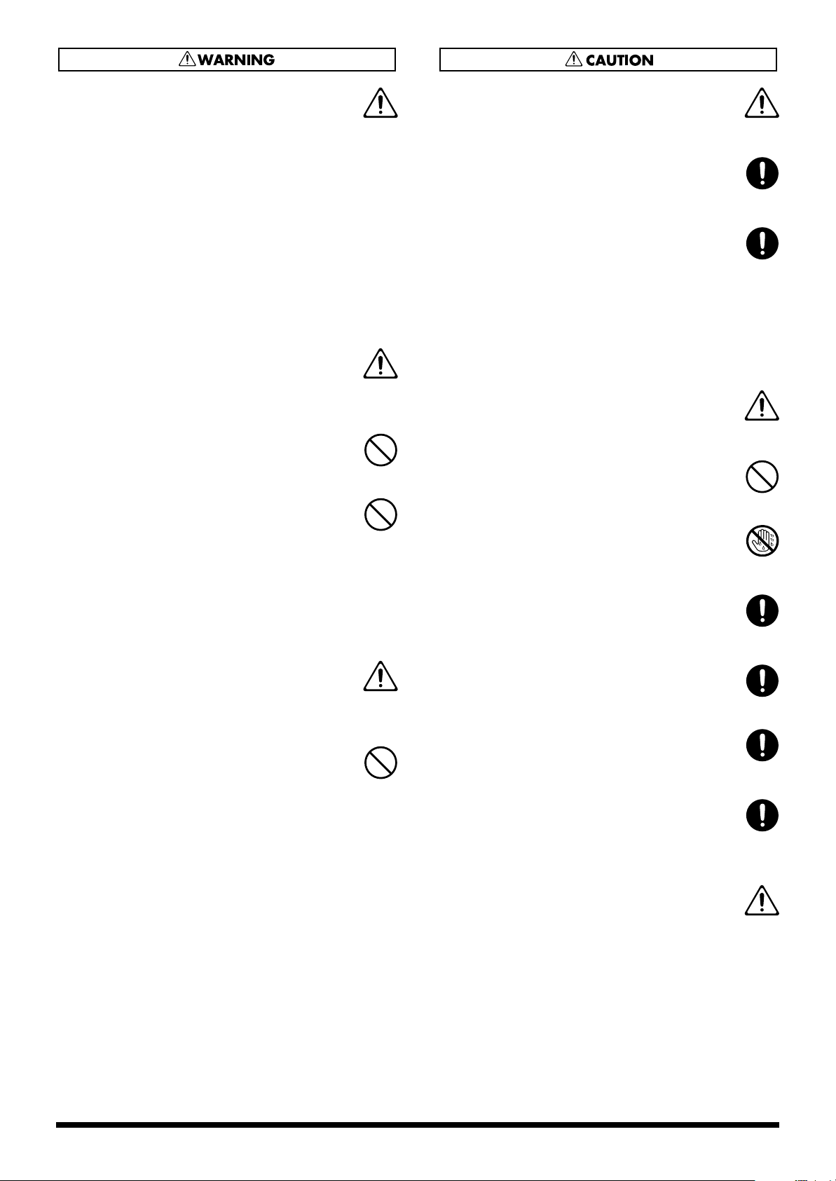
Removing a CD-R/RW disc
1.
Hold the stopper downward and remove a CD-R/RW
disc from outer rim.
fig.CD eject
If a disc tray does not open
If the power is turned off with the disc still in the drive (such
as due to a power failure), the disc tray cannot be opened by
pressing the eject button. In this case, you can insert a piece
of wire to force the tray open.
fig.Hole
Make sure the BR-1600CD’s power has been turned OFF
before attempting to use the emergency eject hole. If you
insert something while the power is on, the disc could get
damaged, or unexpected problems may occur.
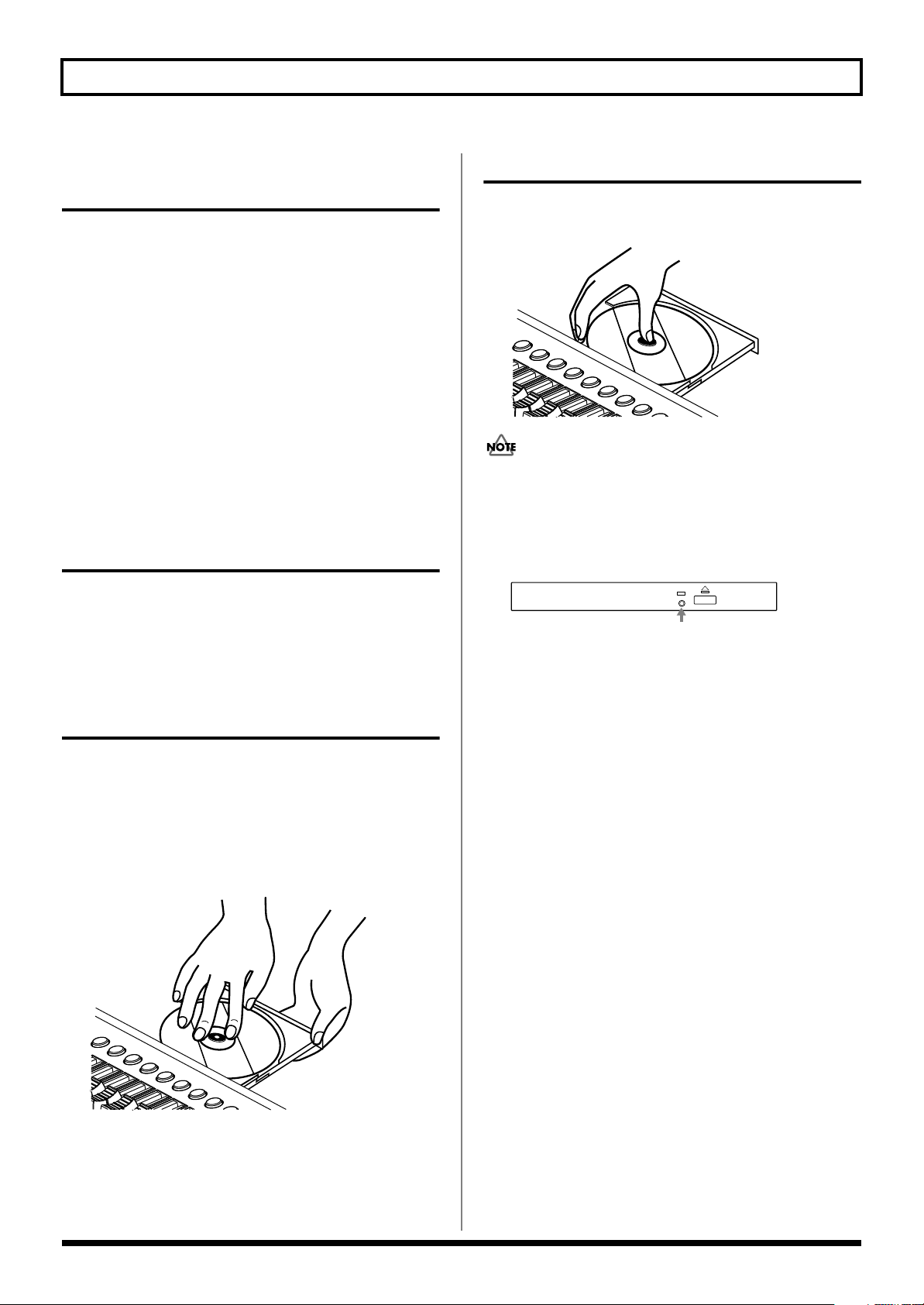
1.
Press the eject button and open a disc tray.
2.
Pull out a disc tray.
3.
Locate the position of center hole of CD-R/RW disc at
stopper of CD-R/RW drive.
4.
Press the CD-R/RW disc downward. The CD-R/RW
disc will be locked by 3 clips of the stopper.
fig.CD set
* As a certain amount of force must be applied for insertion,
always confirm that the CD-R/RW disc has been correctly
inserted. Failure to properly and fully insert a disc can result
in an inability to carry out writing correctly.
5.
Press disc tray until it is locked in the BR-1600CD.
8
Page 9
About the CD-ROM “Discrete Drums”
A CD-ROM is supplied with the BR-1600CD.
The CD-ROM includes a variety of drum phrases created by Discrete Drums.
These professionally recorded drum parts are saved as Loop Phrases that can easily be imported directly into the BR-1600CD and
used in your songs.
Drum phrases are categorized and sorted under each folder in .WAV format files.
The BR-1600CD allows you to easily use these phrases by using the Loop Phrase Import function.
This CD-ROM is not an Audio CD. This CD-ROM should not be played with a consumer audio CD player. If it is, very loud
noises can be generated and audio equipment such as CD players, amplifiers or speakers can be damaged!!
Since all the data included in this CD-ROM has already been factory-installed in the User bank of the Loop Phrase area of the BR-
1600CD, you can easily use the Loop Phrase functions and add the audio to your tracks without using this CD-ROM.
However, in case you initialize your hard disk drive in the BR-1600CD, or accidentally erase the User Loop Phrases, you can
recover all of the factory-installed Loop Phrases by importing them from this CD-ROM.
To import Loop Phrases from this CD-ROM, refer to “Create Loop Phrase” in “Section 3 Using Rhythm.” (“Using wave
data on a CD-ROM/R/RW disc (Loop Phrase Import)” (p. 180))
For more information about the factory-installed Loop Phrases in the User Bank, which are the original WAV files on this CD-
ROM, please refer to “User Loop Phrase List” (separate sheet).
9
Page 10

Contents
USING THE UNIT SAFELY......................................................................2
IMPORTANT NOTES ...............................................................................4
Precautions Regarding the Hard Disk ..................................................6
Before Using CD-R/RW Discs ................................................................7
About the CD-ROM “Discrete Drums” ..................................................9
Introduction to the BR-1600CD............................................................22
Main Features............................................................................................................................ 22
Panel Descriptions................................................................................24
Control Surface......................................................................................................................... 24
CD-R/RW drive .......................................................................................................................... 30
Display ....................................................................................................................................... 31
Rear Panel ................................................................................................................................. 32
Front Panel ................................................................................................................................ 34
Extra information on jacks and connectors .......................................35
Input jacks and connectors ..................................................................................................... 35
GUITAR/BASS jack...................................................................................................................... 35
INPUT 1/MIC 1 jack..................................................................................................................... 35
INPUT 2/MIC 2 jack..................................................................................................................... 35
INPUT 3/MIC 3 jack through INPUT 8/MIC 8 jack ...............................................................35
DIGITAL IN connector................................................................................................................. 35
Output jacks and connectors .................................................................................................. 36
LINE OUT jacks............................................................................................................................. 36
DIGITAL OUT connector............................................................................................................. 36
PHONES 1 and PHONES 2 jack ................................................................................................. 36
MIDI connectors........................................................................................................................ 36
MIDI IN connector........................................................................................................................ 36
MIDI OUT connector.................................................................................................................... 36
USB connector.......................................................................................................................... 37
Power supply ............................................................................................................................ 37
DC IN (AC adaptor) jack.............................................................................................................. 37
Common operations and display items..............................................38
Top screen................................................................................................................................. 38
Current position........................................................................................................................ 38
FUNCTION buttons ([F1] through [F4])................................................................................... 38
PAGE SCROLL buttons............................................................................................................ 39
Scroll Bar................................................................................................................................... 39
Cursor ........................................................................................................................................ 39
TIME/VALUE dial....................................................................................................................... 40
VALUE 1/PAN, VALUE 2, VALUE 3, and VALUE 4 knobs ..................................................... 40
10
Page 11

Contents
Section 1 Advanced Use ...............41
Re-recording only the portion that is mistaken (Punch In/Out) .......42
Manual punch in and punch out.............................................................................................. 42
Performing manual punch in and punch out using [REC]..................................................... 42
Performing manual punch in and punch out using a foot switch......................................... 43
Auto punch in and punch out.................................................................................................. 43
Specifying the section to be re-recorded.................................................................................... 43
Performing auto punch in and punch out................................................................................. 44
Repeating recording in a specific section (Loop Recording)............................................... 45
Specifying the section to be repeated......................................................................................... 45
Specifying the section to be recorded......................................................................................... 45
Performing loop recording ..........................................................................................................45
Using V-Tracks......................................................................................46
Switching V-Tracks................................................................................................................... 46
Assigning names to V-Tracks (Track Name).......................................................................... 47
Changing the V-Track to be written to an audio CD (the Final Mastering Track) ............... 47
Placing markers in your song (Marker) ..............................................48
Basic marker operations.......................................................................................................... 48
Positioning a marker..................................................................................................................... 48
Clearing markers........................................................................................................................... 48
Moving to markers........................................................................................................................ 48
Editing markers......................................................................................................................... 49
Moving markers ............................................................................................................................ 49
Naming a marker .......................................................................................................................... 49
Assigning an audio-CD song division to a marker.................................................................. 49
Changing scenes assigned to markers ....................................................................................... 50
Stopping automatically at a marker (Marker Stop) ................................................................. 50
Registering and recalling mixer settings (Scene)..............................51
Registering, recalling, and deleting scenes........................................................................... 51
Recalling a scene without changing track volumes.............................................................. 51
Recalling scenes automatically during recording or playback (Auto Scene)
Setting an Auto Scene.............................................................................................................. 52
Clearing an Auto Scene ........................................................................................................... 52
Disabling Auto Scene............................................................................................................... 53
Setting Auto Scene control of effects and track EQ ............................................................. 53
....52
Finding the start or end of a section of audio (Scrub/Preview)........54
Using Scrub to find the start of a section of audio ............................................................... 54
Changing the scrubbing direction .......................................................................................... 55
Using Scrub and Preview to find the end of a section of audio........................................... 55
Enabling Preview .......................................................................................................................... 55
Using Scrub and Preview............................................................................................................. 55
11
Page 12

Contents
Editing a recorded performance (Track Edit).....................................56
Precautions when editing tracks............................................................................................. 56
Copying audio data (Track Copy) ........................................................................................... 56
Moving audio data (Track Move) ............................................................................................. 58
Exchanging audio data (Track Exchange) ............................................................................. 60
Inserting a blank space between audio data (Track Insert).................................................. 61
Deleting audio data and closing the resulting gap (Track Cut)............................................ 62
Erasing audio data (Track Erase)............................................................................................ 63
Maximizing the volume levels of data recorded to the tracks
(Normalize) ............................................................................................65
Organizing your songs.........................................................................67
Displaying song details (Song Information) .......................................................................... 67
Copying songs (Song Copy) ................................................................................................... 68
Erasing songs (Song Erase).................................................................................................... 69
Making the most of hard disk capacity (Song Optimize) ...................................................... 70
Protecting a song (Song Protect)............................................................................................ 71
Protecting a song (Song Protect) ................................................................................................. 71
Removing song protection........................................................................................................... 71
Naming a song (Song Name)................................................................................................... 72
Saving your song (Song Save)................................................................................................ 72
Section 2 Using Effects .................. 73
Makeup of BR-1600CD effects .............................................................74
Using insert effects...............................................................................76
Effect patches and banks ........................................................................................................76
Makeup of effect patches......................................................................................................... 77
Modifying insert effect settings............................................................................................... 77
Changing the sound of insert effects using the VALUE knobs.............................................. 78
Changing parameters assigned to VALUE knobs.................................................................... 78
Changing effect block connections ............................................................................................. 79
Switching compressors, equalizers, and low-cut filters between stereo and mono ......... 80
Saving insert effect settings (Effect Patch Write).................................................................. 81
Copying insert effect settings (Effect Patch Copy) ............................................................... 82
Changing insert effect connections........................................................................................ 82
Using an expression pedal ...................................................................................................... 84
Insert effect algorithm list ....................................................................85
BANK: GUITAR ......................................................................................................................... 85
1. COSM OD GUITAR AMP ....................................................................................................... 85
2. ACOUSTIC SIM ........................................................................................................................ 85
3. BASS SIM.................................................................................................................................... 85
4. COSM COMP GUITAR AMP.................................................................................................. 86
5. ACOUSTIC GUITAR................................................................................................................ 86
12
Page 13

Contents
6. BASS MULTI.............................................................................................................................. 86
7. COSM BASS AMP..................................................................................................................... 86
8. COSM COMP BASS AMP........................................................................................................ 87
BANK: MIC................................................................................................................................. 87
9. VOCAL MULTI ......................................................................................................................... 87
10. VOICE TRANSFORMER .......................................................................................................87
11. COSM VOCAL COMP ........................................................................................................... 87
12. MIC MODELING .................................................................................................................... 88
BANK: STEREO ........................................................................................................................ 88
13. STEREO MULTI ...................................................................................................................... 88
14. LO-FI BOX................................................................................................................................ 88
BANK: SIMUL ............................................................................................................................ 88
15. VO+GT.AMP ...........................................................................................................................88
16. VO+AC.SIM............................................................................................................................. 89
17. VO+ACOUSTIC ...................................................................................................................... 89
BANK: MULTI-CHANNEL ......................................................................................................... 89
18. 8CH COMP EQ........................................................................................................................ 89
Insert effect parameter functions ........................................................90
Acoustic Guitar Simulator .......................................................................................................90
Acoustic Processor .................................................................................................................. 90
3 Band Equalizer....................................................................................................................... 91
4 Band Equalizer....................................................................................................................... 91
Bass Simulator.......................................................................................................................... 92
Bass Cut Filter .......................................................................................................................... 92
Chorus ....................................................................................................................................... 92
2x2 Chorus ................................................................................................................................ 92
Compressor............................................................................................................................... 93
COSM Comp/Limiter (COSM Compressor/Limiter) ............................................................... 94
COSM Overdrive/Distortion ..................................................................................................... 94
COSM PreAmp&Speaker.......................................................................................................... 95
De-esser..................................................................................................................................... 96
Defretter..................................................................................................................................... 96
Delay .......................................................................................................................................... 97
Distance..................................................................................................................................... 97
Doubling .................................................................................................................................... 97
Enhancer ................................................................................................................................... 98
Flanger....................................................................................................................................... 98
Foot Volume .............................................................................................................................. 98
Humanizer ................................................................................................................................. 98
Limiter........................................................................................................................................ 99
Low Cut Filter............................................................................................................................ 99
Lo-Fi Box ................................................................................................................................... 99
Mic Converter.......................................................................................................................... 100
Noise Suppressor ................................................................................................................... 100
Octave...................................................................................................................................... 100
Pan ........................................................................................................................................... 101
Phaser...................................................................................................................................... 101
Pickup Simulator .................................................................................................................... 101
13
Page 14

Contents
Pitch Shifter............................................................................................................................. 102
Preamp..................................................................................................................................... 103
Ring Modulator ....................................................................................................................... 104
Short Delay.............................................................................................................................. 104
Slow Gear ................................................................................................................................ 104
Speaker Simulator .................................................................................................................. 104
Sub Equalizer .......................................................................................................................... 105
Tremolo.................................................................................................................................... 105
Tremolo/Pan ............................................................................................................................ 105
Uni-V ........................................................................................................................................ 105
Vibrato ..................................................................................................................................... 106
Voice Transformer .................................................................................................................. 106
Wah .......................................................................................................................................... 106
Using track-specific compressors and equalizers ..........................108
Compressors and equalizers................................................................................................. 108
Compressor and equalizer connections .............................................................................. 108
Adjusting the sound of compressors and equalizers ......................................................... 109
Adjusting a compressor ............................................................................................................. 109
Selecting tracks to be compressed ............................................................................................ 110
Switching compressors between stereo and mono (Stereo Link) ........................................110
Adjusting a three-band equalizer .............................................................................................110
Switching equalizers between stereo and mono (Stereo Link) ............................................ 111
Using loop effects...............................................................................112
About loop effects .................................................................................................................. 112
About loop effect connections .............................................................................................. 112
Basic loop effect operations.................................................................................................. 113
Adjusting the sound of loop effects.......................................................................................... 113
Adjusting reverb.......................................................................................................................... 113
Adjusting chorus ......................................................................................................................... 114
Adjusting delay ...........................................................................................................................114
Adjusting doubling..................................................................................................................... 115
Fixing the pitch of vocals/
Adding a backing chorus to vocals (Vocal Tool Box) .....................116
The Vocal Tool Box ................................................................................................................ 116
Makeup of the Vocal Tool Box............................................................................................... 116
Vocal Tool Box patches ......................................................................................................... 117
Fixing the pitch of vocals (Pitch Correction) ....................................................................... 117
Setting the correction method for vocal pitch (Pitch Correction Edit).............................. 118
Applying a backing chorus to vocals (Harmony Sequence) .............................................. 119
Inserting rests in a backing chorus ...................................................................................... 120
Setting the application method for backing choruses (Harmony Sequence Edit) ........... 120
Saving Vocal Tool Box settings (Patch Write) ..................................................................... 121
Copying Vocal Tool Box settings (Patch Copy) .................................................................. 122
14
Page 15

Contents
Recreating the characteristics of
different monitor speakers (Speaker Modeling) ..............................123
Makeup of Speaker Modeling ................................................................................................ 123
Connecting external monitor speakers ................................................................................ 123
Speaker Modeling patches .................................................................................................... 124
Using Speaker Modeling ........................................................................................................ 124
Turning off Speaker Modeling.................................................................................................. 124
Modifying Speaker Modeling settings .................................................................................. 124
Saving Speaker Modeling settings (Patch Write) ................................................................ 125
Copying Speaker Modeling settings (Patch Copy).............................................................. 126
Speaker Modeling parameter functions............................................127
SP Modeling (speaker modeling) .......................................................................................... 127
Bass Cut Filter ........................................................................................................................ 128
Low Freq Trimmer .................................................................................................................. 128
High Freq Trimmer.................................................................................................................. 128
Limiter...................................................................................................................................... 128
Using the Mastering Tool Kit .............................................................129
The Mastering Tool Kit ........................................................................................................... 129
Makeup of the Mastering Tool Kit ......................................................................................... 129
Modifying Mastering Tool Kit settings (Edit) ....................................................................... 130
Saving Mastering Tool Kit settings (Patch Write)................................................................ 131
Copying Mastering Tool Kit settings (Patch Copy) ............................................................. 131
Performing automatic fade-in and fade-out (Auto Fade In/Out)......................................... 132
Performing automatic fade-in (Auto Fade In) ........................................................................132
Performing automatic fade-out (Auto Fade Out)................................................................... 133
Mastering Tool Kit parameter functions ...........................................134
Equalizer.................................................................................................................................. 134
Bass Cut Filter ........................................................................................................................ 135
Enhancer ................................................................................................................................. 135
Input ......................................................................................................................................... 135
Expander ................................................................................................................................. 135
Compressor............................................................................................................................. 136
Mixer ........................................................................................................................................ 136
Limiter...................................................................................................................................... 136
Output ...................................................................................................................................... 136
Effect parameters assigned to VALUE knobs.................................137
15
Page 16

Contents
Section 3 Using Rhythm .............. 145
Makeup of Drum/Bass/Loop Phrase .................................................146
Drums ...................................................................................................................................... 146
Bass ......................................................................................................................................... 146
Loop Phrases .......................................................................................................................... 147
Rhythm arrangements........................................................................148
Pattern mode and Arrangement mode ................................................................................. 148
Using drums ........................................................................................149
Setting the track type ............................................................................................................. 149
Playing drum sounds ............................................................................................................. 149
Selecting a drum kit................................................................................................................ 150
Selecting drum patterns......................................................................................................... 150
Changing the drum pattern tempo........................................................................................ 151
Setting the tempo using [TAP].................................................................................................. 151
Creating drum patterns ......................................................................152
Preparing for recording.......................................................................................................... 152
Creating drum patterns using real-time recording.............................................................. 153
Practicing before recording (Rehearsal)................................................................................... 154
Recording in perfect time (Quantize)....................................................................................... 154
Creating drum patterns using step recording ..................................................................... 155
Correcting drum patterns (Microscope) ............................................................................... 157
Changing the drum pattern’s groove (Swing)...................................................................... 159
Changing a drum pattern’s name.......................................................................................... 160
Copying drum patterns .......................................................................................................... 160
Deleting drum patterns .......................................................................................................... 161
Loading drum patterns from the CD-R/RW drive (SMF Import) ......................................... 161
Using bass...........................................................................................163
Setting the track type ............................................................................................................. 163
Playing bass............................................................................................................................ 163
Selecting bass sounds........................................................................................................... 164
Selecting bass patterns ......................................................................................................... 164
Specifying bass pattern chords ............................................................................................ 165
Changing the bass pattern’s tempo...................................................................................... 165
Creating bass patterns .......................................................................166
Preparing for recording.......................................................................................................... 166
Creating bass patterns using real-time recording............................................................... 167
Practicing before recording (Rehearsal)................................................................................... 168
Recording in perfect time (Quantize)....................................................................................... 168
Creating bass patterns using step recording ...................................................................... 169
Correcting bass patterns (Microscope)................................................................................ 170
Changing the bass pattern’s groove (Swing) ...................................................................... 172
Changing a bass pattern’s name .......................................................................................... 173
16
Page 17

Contents
Copying bass patterns ........................................................................................................... 173
Deleting bass patterns ........................................................................................................... 174
Loading bass patterns from the CD-R/RW drive (SMF Import) .......................................... 174
Using Loop Phrases ...........................................................................176
Setting the track type ............................................................................................................. 176
Playing Loop Phrases ............................................................................................................ 176
Selecting a Loop Phrase ........................................................................................................ 177
Changing the Loop Phrase tempo ........................................................................................ 178
Setting the tempo using [TAP].................................................................................................. 178
Creating Loop Phrases.......................................................................179
Using a portion of an audio track.......................................................................................... 179
Using wave data on a CD-ROM/R/RW disc (Loop Phrase Import) ..................................... 180
Reading all files at once.............................................................................................................. 181
Specifying and modifying the source loop phrase (Time Modify) ..................................... 182
Modifying Loop Phrase settings ........................................................................................... 183
Assigning Loop Phrases to track buttons ........................................................................... 184
Copying Loop Phrases........................................................................................................... 184
Erasing Loop Phrases............................................................................................................ 185
Setting the Universal Beat for Drums, Bass, and Loop Phrases ...186
Using rhythm arrangements ..............................................................187
Selecting a rhythm arrangement........................................................................................... 187
Changing the rhythm arrangement tempo ........................................................................... 187
Setting the tempo using [TAP].................................................................................................. 188
Creating rhythm arrangements .........................................................189
Assembling drum and bass patterns.................................................................................... 189
Canceling pattern allocations................................................................................................ 189
Inserting patterns ................................................................................................................... 190
Inputting chords ..................................................................................................................... 190
Changing and moving chords ............................................................................................... 191
Deleting chords....................................................................................................................... 191
Inserting chords...................................................................................................................... 191
Assembling Loop Phrases..................................................................................................... 192
Canceling Loop Phrase allocations ...................................................................................... 193
Inserting Loop Phrases.......................................................................................................... 193
Copying a Loop Phrase from a rhythm arrangement to an audio track............................ 193
Modifying all of the loop phrases in the current rhythm arrangement (Arrangement Modify)
Naming and saving rhythm arrangements........................................................................... 196
Copying a rhythm arrangement ............................................................................................ 196
Deleting a rhythm arrangement............................................................................................. 197
....... 195
Setting tempos and beats for individual measures (Tempo Map/Beat Map)
Setting tempos for individual measures (Tempo Map) ....................................................... 198
Setting beats for individual measures (Beat Map) .............................................................. 199
...198
17
Page 18

Contents
Using a metronome ............................................................................200
Setting the track type ............................................................................................................. 200
Playing a metronome ............................................................................................................. 200
Selecting metronome sounds ............................................................................................... 201
Selecting outputs for the metronome................................................................................... 201
Section 4 Using the CD-R/RW Drive
.. 203
Using the CD-R/RW drive to exchange data.....................................204
Storing of songs and other hard-disk data to CD-R/RW discs (Backup) .......................... 204
Backing up a song (Song Backup) ............................................................................................ 204
Backing up user data (User Backup) ........................................................................................ 205
Backing up all data on the hard disk (HDD Backup) ............................................................ 206
Reading songs and other backup data back into the hard disk (Recover)....................... 207
Reading backup songs back into the hard disk (Song Recover) ..........................................207
Reading backup user data back into the hard disk (User Recover)..................................... 208
Reading backed-up hard disk contents back into the hard disk (HDD Recover) .............209
Copying and writing waveform data .................................................210
Copying waveform data from a computer to the audio tracks (WAV/AIFF Import).......... 210
Copying audio track waveform data to computers (WAV/AIFF Export) ............................ 211
Playing SMFs using external MIDI instruments (SMF Player) ............................................ 213
Erasing data from a CD-RW disc........................................................................................... 214
Setting the time until the CD-R/RW drive stops (CD Hold Time)........................................ 215
Convenient functions for audio CD creation....................................216
Precautions ............................................................................................................................. 216
Setting the time between songs (Pre-Gap) .......................................................................... 216
Erasing CD-RW discs (CD-RW Erase) .................................................................................. 217
Enabling playback on CD players (Finalize) ........................................................................ 218
Importing songs from CDs to audio tracks (Audio CD Import).......................................... 219
Section 5 Using MIDI................... 221
MIDI fundamentals ..............................................................................222
What is MIDI? .......................................................................................................................... 222
MIDI connectors...................................................................................................................... 222
MIDI channels.......................................................................................................................... 222
MIDI Implementation Charts .................................................................................................. 222
Playing drum and bass patterns on external MIDI sound module
Drum sounds and note numbers .......................................................................................... 224
Synchronizing external MIDI sequencers and rhythm machines...225
Synchronizing a MIDI device to the rhythm’s tempo using the MIDI timing clock........... 225
18
............223
Page 19

Contents
Synchronizing a MIDI sequencer to the playback time using MTC ................................... 226
Changing the TIME field display.............................................................................................. 228
Synchronizing a MIDI device by recording its tempo changes on the BR-1600CD (Sync Track)
Setting the starting time of synchronization (Sync Offset) ................................................ 230
.......... 228
Controlling MMC-compatible devices from the BR-1600CD...........231
Controlling track volumes via MIDI (MIDI Fader) .............................232
Turning MIDI Fader on and off............................................................................................... 232
Setting the MIDI channel for MIDI Fader............................................................................... 233
Confirming the current fader positions ................................................................................ 233
Inputting drum and bass patterns
from a MIDI keyboard (MIDI Recording)............................................234
Using MIDI to Control the Switching
of the Insert Effects (Effects Program Change) ...............................235
Controlling external video devices from the BR-1600CD (V-LINK)
What is V-LINK?...................................................................................................................... 236
What can V-LINK do? ............................................................................................................. 236
Connecting V-LINK devices................................................................................................... 236
Using V-LINK........................................................................................................................... 236
Changing V-LINK function assignments .............................................................................. 237
Recording and playing V-LINK control operations ............................................................. 238
Recording control operations .................................................................................................... 238
Playing recorded control operations........................................................................................ 238
Erasing recorded control operations ........................................................................................ 238
...........236
Section 6 Using USB....................239
Before Using USB (Overview)............................................................240
Operations that can be performed via USB ......................................................................... 240
Compatible OS ........................................................................................................................ 240
Connecting a computer.......................................................................................................... 241
Structure of data on the BR-1600CD’s hard disk................................................................. 241
Backing up the BR-1600CD’s data ....................................................242
With Windows ......................................................................................................................... 242
With Macintosh ....................................................................................................................... 243
Reading backup data
back into the BR-1600CD from the PC (Recover) ............................245
With Windows ......................................................................................................................... 245
With Macintosh ....................................................................................................................... 246
19
Page 20

Contents
Saving BR-1600CD track data
in WAV/AIFF format (WAV/AIFF Export) ...........................................248
With Windows ......................................................................................................................... 248
With Macintosh ....................................................................................................................... 250
Loading WAV/AIFF files
in BR-1600CD tracks (WAV/AIFF Import)..........................................252
With Windows ......................................................................................................................... 252
With Macintosh ....................................................................................................................... 253
Section 7 Other Convenient Functions
.....255
Tuning instruments (Tuner) ...............................................................256
Setting the reference pitch .................................................................................................... 256
Tuning...................................................................................................................................... 256
Automatically adjusting the input volume balance (Level Calibration)
Automatically adjusting the volume balance....................................................................... 258
Restoring the original volume balance................................................................................. 258
Manually adjusting the input volume balance ..................................................................... 259
.....258
Muting individual inputs.....................................................................260
Inputting audio with no loss of quality (Digital In Assign)..............261
Creating a master tape protected from digital copying ..................262
Changing the content of the level meter display (Pre/Post Fader)
...........263
Using condenser microphones (Phantom Power)...........................264
Mixing audio-device output
with the BR-1600CD’s output (Audio Sub Mix) ................................266
Initializing all BR-1600CD settings (Initialize) ..................................267
Performing hard disk operations ......................................................269
Viewing information about the hard disk (Hard Disk Information) .................................... 269
Initializing the hard disk (Disk Initialize)............................................................................... 270
Initializing only one of multiple partitions............................................................................ 271
20
Page 21

Contents
Appendices ................................273
Troubleshooting..................................................................................274
Error Messages ...................................................................................277
Operation of the INPUT SELECT buttons .........................................280
Internal connection diagrams for each INPUT SELECT condition .................................... 281
When [GUITAR/BASS] is selected .......................................................................................... 281
When [VOCAL] is selected........................................................................................................ 282
When [SIMUL] is selected.......................................................................................................... 282
When [MULTI-TRACK] is selected.......................................................................................... 283
When [STEREO TRACKS] is selected ...................................................................................... 284
REC MODE (Recording Mode) Operations .......................................285
Internal connection diagrams for each recording mode .................................................... 286
When INPUT or BOUNCE is selected .....................................................................................286
When MASTERING is selected................................................................................................. 287
MIDI Implementation...........................................................................288
Specifications......................................................................................295
Index.....................................................................................................297
21
Page 22

Introduction to the BR-1600CD
■
Main Features
■
Ease of use
The BR-1600CD has been designed so that even
beginners will be able to use it in the same way as a
standard tape recorder. In addition, it features a large
LCD screen for the presentation of all types of
information in graphic format. Regardless of whether
you want to record your band, put together a demo, or
create a finished audio CD, you will be able to put the
BR-1600CD to use as soon as you take it out of the box.
Novices and experts alike can fully enjoy the thrilling
world of digital recording using this advanced digital
audio workstation.
■
Digital processing of audio
In addition to a digital mixer and a digital hard-disk
recorder, the BR-1600CD also features a programmable
drum and bass sequencer and comes with a full
complement of digital effects. All the steps needed for
professional-level music recording, such as the editing of
recorded performances, track bouncing, the application
of effects, and mix-down can be carried out completely
within the digital domain, thus ensuring that there will
be no degradation in the quality of your audio.
■
CD-quality digital sound
The BR-1600CD records and plays back digital audio at a
sampling rate of 44.1 kHz and with an uncompressed
linear bit depth of 16 bits—exactly the same as
commercially available music CDs. Thanks to this, you
can record musical performances with no loss of audio
quality whatsoever.
■
16-track simultaneous playback
The BR-1600CD digital audio workstation features 8
tracks for mono recording and playback in addition to 8
tracks for recording and playback in stereo; furthermore,
all 16 of these tracks can be played back at the same time.
■
8-track simultaneous recording
Equipped with 8 independent input channels, the BR1600CD can simultaneously record the input from each
of these channels onto 8 independent audio tracks—an
excellent feature when you are recording drums or other
performances using multiple microphones.
■
V-Tracks
Each of the BR-1600CD’s audio tracks provides 16 VTracks (or virtual tracks), allowing you to record as
many as 256 (16 x 16) different performances. If, for
example, you want to record multiple takes of a guitar
solo so that the best can be chosen later on, this feature
allows you to do so with ease.
A host of digital effects
The BR-1600CD provides you with a full range of
powerful effects for many different situations. In specific
terms, Insert Effects are used during recording, Loop
Effects work like standard send/return effects, the
Mastering Tool Kit allows you to master finished songs,
the Vocal Tool Box cleans up vocal tracks, and Speaker
Modeling allows you to hear how your songs would
sound on different speaker systems. With this arsenal at
your disposal, you will be able to make professionalsounding recordings using just the BR-1600CD—without
having to rely on external effects processors. In addition
to COSM amplifier modelings inherited straight from
the BOSS GT-6, the Insert Effects feature a wealth of
other modelings and effects algorithms. And rather than
being restricted to use with guitars alone, the Insert
Effects also provide wide-ranging support for 8-track
simultaneous recording, microphone modeling, and
many other applications. What’s more, the Loop Effects
include spatial effects such as chorus, delay and reverb,
which are vital for proper stereo mixdown.
■
Vocal Tool Box for better-sounding
vocals
The BR-1600CD’s Vocal Tool Box empowers you with
the ability to fix incorrect pitches in recorded vocal
performances and to automatically apply vocal
harmonies to your vocal tracks.
■
Mastering Tool Kit for professionalsounding CDs
The Mastering Tool Kit integrated into the BR-1600CD
allows you to make final adjustments to the volume and
other characteristics of mixed songs. Featuring an
equalizer and limiter in addition to a 3-band compressor,
this tool kit makes it easy to balance the volume and
power of songs before they are written to an audio CD.
■
Powerful editing functions
With the BR-1600CD, you can copy, move, and erase
audio, and perform many other editing operations that
are only possible with full digital recorders. For example,
you could repeat a certain four-measure drum pattern
over and over to create a break-beats sound;
alternatively, you could easily position the exact same
chorus section at the beginning and end of a song.
What’s more, the BR-1600CD uses a process known as
Non-Destructive Editing to store the data from before a
edit, and as a result, you can use functions known as
Undo and Redo to cancel and restore edits.
“Rectifying recording mistakes (Undo/Redo)” (Basic
Operation; p. 42)
22
Page 23
■
Saving of mixer settings
The term Scene is used to describe a batch of BR-1600CD
mixer and effect settings, and up to 100 scenes can be set
up and stored for each song. Accordingly, these settings
can be conveniently recalled whenever you are
balancing volumes during mix-down, comparing the
sound of different effects, or performing other similar
operations. In addition, another BR-1600CD function
known as Auto Scene allows registered scenes to be
recalled automatically during playback.
“Registering and recalling mixer settings (Scene)” (p. 51)
■
Rapid relocation of the current position
The BR-1600CD’s Marker function allows you to position
as many as 100 different markers at various points
within your song. For example, if you position markers
at the end of the intro, the beginning of the guitar solo,
and other similar points, you will be able to jump to
these points in an instant whenever you want to listen to
the corresponding sections again. You can also assign
names to any or all of these markers, and this proves
extremely helpful during involved editing sessions.
“Placing markers in your song (Marker)” (p. 48)
■
PCM Drum/Bass
A PCM Drum/Bass (p. 146) capable of sequencing drum
and bass patterns has been integrated into the BR1600CD, and you will find this extremely useful
whenever you need to put together songs based on
phrases or other ideas that can come to you at any time.
Once you have chosen the drum and bass patterns that
best suit your idea, you can easily set the tempo to the
right speed. What’s more, you can also combine different
drum and bass patterns to create a rhythm-section
performance with interesting variations at appropriate
points during your song, and the PCM Drum/Bass also
allows you to set up chord progressions for the bass part.
Once you have played and recorded tracks along with
the BR-1600CD’s PCM Drum/Bass, it will then be very
easy to perform edits at measure positions.
Introduction to the BR-1600CD
■
Loop phrase functionality
The BR-1600CD lets you import commercially available
loop phrase data using the CD- R/RW drive and then
save this data on the internal hard disk. The tempo for
these loop phrases can then be freely set to the required
speed so that they can be played in sync with your
recorded tracks. Using this function, you can easily
create songs by layering performances over break beats
or other rhythm patterns.
■
Creation of audio and backup CDs
The BR-1600CD comes with its own CD-R/RW drive
already installed, and you can use this to easily create
audio CDs by burning your finished songs onto CD-R
discs. In addition, the CD-R/RW drive also allows you
to use CD-R/RW discs to conveniently back up songs
and song data.
Before you use the CD-R/RW drive, it is important that
you first of all read “Before Using CD-R/RW Discs” (p.
7).
■
Chromatic tuner
Featuring a chromatic tuner covering the range from C1
to B6, the BR-1600CD allows you to quickly tune any
guitar or bass guitar connected to it (p. 256).
■
Automatic level calibration
Using a function called Level Calibration, the BR1600CD Digital Recording Studio can detect and
automatically balance the volumes of its various input
(p. 258).
“Section 3 Using Rhythm” (p. 145)
23
Page 24
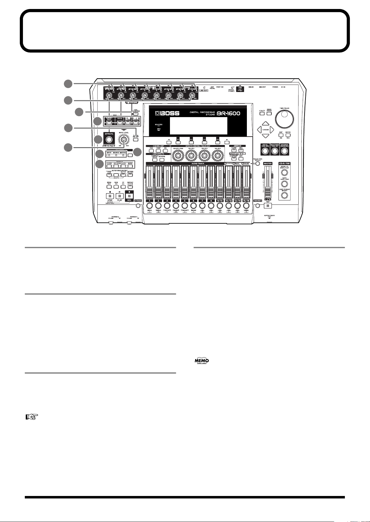
Panel Descriptions
Control Surface
fig.05-01a
2
1
3
4
7
5
6
9
10
8
1. INPUT SENS knobs
These knobs are used to adjust the sensitivity of the
corresponding input jacks. Note that the INPUT SENS 1
knob also adjusts the sensitivity of the GUITAR/BASS jack.
2. PEAK indicators
These indicators allow you to confirm whether or not the
audio being input via the corresponding input jack is
distorting, and they do this by lighting up when the volume
reaches the distortion level of -6 dB. Use the INPUT SENS
knobs to adjust the input sensitivity in such a way that each
PEAK indicator only lights up occasionally when the
corresponding instrument is being played hard.
3. LEVEL CALIBRATION button
When a number of instruments are connected to different
input jacks, you can use [LEVEL CALIBRATION] to
automatically adjust and balance the corresponding input
volumes.
“Automatically adjusting the input volume balance
(Level Calibration)” (p. 258)
4. INPUT SELECT buttons
Use these buttons to select the input source (input jack) that
you wish to record. The indicater of the selected button will
light. If a lit INPUT SELECT button is pressed, it will turn off
and the corresponding input source(s) will be muted.
GUITAR/BASS:
This button is used to select either the GUITAR/BASS jack
for recording guitar or bass or the INPUT 1/MIC 1 jack for
recording from a line-in or a microphone. Note that the
GUITAR/BASS jack will be selected automatically when an
instrument is connected to it.
* When either [GUITAR/BASS] or [VOCAL] is alone selected,
Adaptive Focus (AF) will be activated for recording.
What is AF method (Adaptive Focus method)?
Adaptive Focus is a unique Roland technology that
allows the signal noise (S/N) ratios of AD and DA
converters to be vastly improved.
VOCAL:
This button is used to select the INPUT 2/MIC 2 jack for
recording from a line-in or a microphone.
SIMUL:
SIMUL mode is activated by holding down [GUITAR/BASS]
and pressing [VOCAL]. In this condition, either the
GUITAR/BASS or the INPUT 1/MIC 1 jack will be selected
together with the INPUT 2/MIC 2 jack. In other words, two
inputs will be simultaneously selected. Note that the
GUITAR/BASS jack will be selected automatically when an
instrument is connected to it.
24
Page 25
Panel Descriptions
MULTI-TRACK:
All input sources are selected in MULTI-TRACK mode.
When this mode is used, each source will be recorded on the
corresponding track (i.e., 1 through 8 or 9/10 through 15/16).
STEREO TRACKS:
All input sources are selected in STEREO TRACKS mode. In
this case, the audio from the input sources will be mixed in
stereo and then recorded on the track selected for recording.
If you wish to read more about the operation of the INPUT
SELECT buttons, refer to “Operation of the INPUT SELECT
buttons” (p. 280).
5. EFFECTS button
Use this button to select an insert effects’ patch (p. 74) and to
call up the screen for editing effects settings and the like.
6. INPUT LEVEL knob
Adjusts the volume of all input sources, and the volumes
determined using this knob are the actual volumes that will
be recorded on tracks.
When either [MULTI-TRACK] or [STEREO TRACKS] has
been selected from INPUT SELECT, you can use this knob to
adjust the overall volume while maintaining the balance of
volumes set up for the various input sources.
7. TUNER ON/OFF button
Use this button to turn the tuner (p. 256) on and off.
8. REC MODE (recording mode) button
This is used to prepare the BR-1600CD for recording. In
addition, it also allows you to select one of the following
three recording modes:
INPUT:
Allows you to record the instruments and microphones
connected to the input jacks. The units is normally used in
this mode.
9.
REC MODE (recording mode) indicators
Allow you to confirm which recording mode is currently
selected. Whenever you change the recording mode using
the REC MODE button, the INPUT, BOUNCE, or
MASTERING indicator will light up accordingly.
10. MARKER
The MARKER section is used to make settings for the marker
function.
MARK button:
Use this button to position a marker at any point within your
song. Each time this button is pressed, the BR-1600CD will
place a marker at the current position.
Markers are numbered in sequence from the beginning of the
song. In addition, you can also assign names to individual
markers. If a marker has been placed at the current position,
the corresponding number will appear in the display’s
Marker box; if no marker has been placed here, the Marker
box will show the number of the last marker before the
current position. Appropriately placed markers allow you to
quickly confirm which section of the song is being played.
“Placing markers in your song (Marker)” (p. 48)
SEARCH button:
Use this button to jump back to the previous marker before
the current position.
SEARCH button:
Use this button to jump forward to the next marker after the
current position.
CLEAR button:
Use this button to delete markers. Specifically, the marker
currently being shown in the display’s Marker box will be
deleted when this button is pressed.
BOUNCE:
Allows you to mix the audio from several tracks and to
record it on one or two different tracks.
MASTERING:
Allows you to master your finished songs using the BR1600CD’s Mastering Tool Kit.
If you wish to read more about the various recording modes,
refer to “REC MODE (Recording Mode) Operations” (p. 285).
25
Page 26
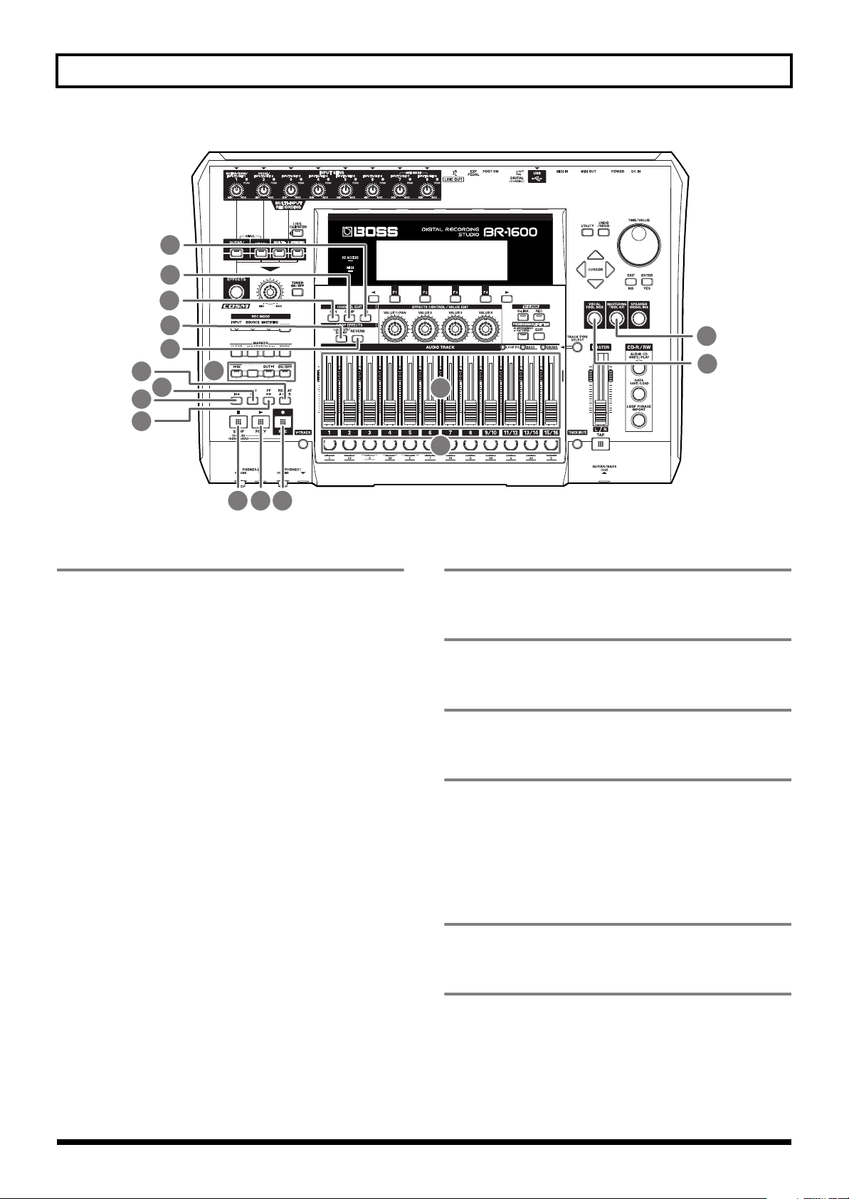
Panel Descriptions
fig.05-01b
21
20
19
22
23
15
11
13
12
14
16 17 18
11. AUTO PUNCH IN/OUT
The AUTO PUNCH IN/OUT section is used to make settings
for the auto punch in/out function.
ON/OFF button:
This button is used to turn the auto punch function on and
off. The button’s indicator will light up when auto punch is
on.
IN button:
Sets the punch-in position. When pressed, the current
position is registered as the punch-in position and the
button’s indicator lights up. Once a punch-in position has
been registered, you can jump to this position at any time by
pressing [IN].
OUT button:
Sets the punch-out position. When pressed, the current
position is registered as the punch-out position and the
button’s indicator lights up. Once a punch-out position has
been registered, you can jump to this position at any time by
pressing [OUT].
27
26
24
25
12. ZERO button
Press to jump to the very beginning of the song.
13. REW button
The song will rewind while you hold down this button.
14. FF button
The song will fast-forward while you hold down this button.
15. REPEAT button
Selects a section of your song to listen to repeatedly (“Playing
back repeatedly (Repeat Function)” (Basic Operation; p. 17)).
This function is useful when you want to record several
times using punch-in and punch-out (p. 42) before saving the
best performance.
16. STOP button
This button stops song playback or recording.
DELETE button:
Deletes the current punch-in or punch-out position. To do
this, hold down [DELETE] and then press either [IN] or
[OUT] to delete the corresponding auto punch position.
When the [IN] or [OUT] setting is cleared in this way, its
indicator will be turned off.
26
17. PLAY button
Starts playback of your song. Alternatively, if [REC] has been
pressed and its indicator is flashing, you can also start
recording by pressing [PLAY]. During playback or recording,
this button’s indicator will light up in green.
Page 27

Panel Descriptions
18. REC (record) button
This is the BR-1600CD’s record button, and in addition to
normal recording, it is also used to perform manual punch-in
and punch-out. This button’s indicator will turn red and
begin to flash when the BR-1600CD is standing by to start
recording, and this will change to a steady red when
recording is actually started.
19. PAN button
This calls up a screen that allows settings to be made for the
pan (i.e., the left-right position) of each playback track and
input source (Basic Operation; p. 46).
20. COMP (compressor) button
This calls up a screen for setting of each track’s compressor
parameters so that variations in volume may be suppressed
(p. 109).
21. EQ (equalizer) button
This calls up a screen that allows setting of each track’s
equalizer parameters so that the sound of the corresponding
track can be adjusted (p. 110).
22. CHORUS/DELAY button
25. Track buttons 1–8, 9/10–15/16
Track buttons 1 through 8 and 9/10 through 15/16 are used to
select tracks for recording or for the setting of parameters.
Furthermore, they can also be used to select drum and/or bassguitar sounds when you are creating a drum pattern or a bass
pattern. Since tracks 9/10 through 15/16 are fixed as stereo
tracks, a single button simultaneously selects both tracks in the
stereo pair. When a track has been selected for recording, its
track button will turn red and start to flash, and when recording
is started, this will change to a steady red lighting pattern. Then,
when recording has ended, the track button will flash in orange
and green. The relationship between the type of illumination
and the track status is as follows:
Off:
The track contains no audio data (i.e., it has not been
recorded on).
Steady green:
The track contains (recorded) audio data.
Flashing green:
The track contains (recorded) audio data but is currently
muted.
Flashing red:
The track has been selected for recording and the BR-1600CD
is in standby mode for recording.
This calls up either a screen for setting of the send level from
each track to the loop effects chorus/delay, or a screen that
allows selection of chorus or delay effects and the setting of
parameters for these effects (p. 114).
23. REVERB button
This calls up either a screen for setting of the send level from
each track to the loop effect reverb, or a screen that allows
reverb parameters to be set (p. 113).
24. AUDIO TRACK MIXER faders 1–8,
9/10–15/16
These faders are used to control the volumes of the
corresponding tracks during playback.
Since tracks 9/10 through 15/16 are fixed as stereo tracks, a
single fader controls the volume of both tracks in the stereo
pair simultaneously. In addition, the faders for tracks 11/12
through 15/16 are also used to control the volume of rhythm
arrangement components such as loop phrases, bass, and
drums.
Steady red:
The track is being recorded to.
Flashing orange and green:
The track contains recorded audio data and is currently
selected for recording.
Flashing orange:
The track contains recorded audio data, is selected for
recording, but is currently muted.
26. VOCAL TOOL BOX button
Use this button to turn the Vocal Tool Box on and off, and
also to call up a screen for setting of its parameters.
“Fixing the pitch of vocals/Adding a backing chorus to
vocals (Vocal Tool Box)” (p. 116)
27. MASTERING TOOL KIT button
Use this button to turn the Mastering Tool Box on and off,
and also to call up a screen for setting of its parameters.
In this manual, the term “track faders” is used to refer to
the AUDIO TRACK MIXER faders.
“Using the Mastering Tool Kit” (p. 129)
27
Page 28
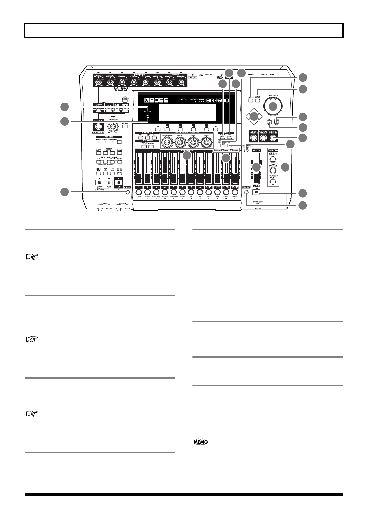
Panel Descriptions
fig.05-01c
48
47
34
28. SPEAKER MODELING button
Use this button to turn the Speaker Modeling on and off, and
also to call up a screen for setting of its parameters.
30 32
39
29 31
40
41
42
43
44
28
36
38
37
45 46
33
35
32. EDIT button
Used to input and set parameters for Drum, Bass, Loop
Phrase and rhythm arrangements (p. 145).
“Recreating the characteristics of different monitor
speakers (Speaker Modeling)” (p. 123)
29. V-LINK button
The V-Link function is used to control external video
equipment, and this button turns it on and off. In addition,
you can also press [V-LINK] to call up a setting screen for VLink parameters.
“Controlling external video devices from the BR-1600CD
(V-LINK)” (p. 236)
V-LINK REC (V-Link recording) button
30.
If you are using the V-Link function to control external video
equipment, this button allows you to replay and/or playback
video-control operations.
“Controlling external video devices from the BR-1600CD
(V-LINK)” (p. 236)
When [ARRANGEMENT/PATTERN] is lit up:
Press [EDIT] to call up a screen for creating rhythm
arrangements and editing the relevant parameters.
When [ARRANGEMENT/PATTERN] is not lit:
Press [EDIT] to call up a screen for creating drum and/or
bass patterns and editing the relevant parameters.
33. TAP button
By tapping this button along with your song, you can set the
tempo for the Drum, Bass and Loop Phrases (p. 151).
34. V-TRACK button
Calls up a screen for selecting V-Tracks (p. 46).
35. TRACK MUTE button
If you hold down [TRACK MUTE] and press a track button
that is currently lit in green, the corresponding track will be
muted (or silenced) during playback. You can then perform
the same procedure once again to cancel muting. While a
track is muted, its track button will flash in green (Basic
Operation; p. 20).
31. ARRANGEMENT/PATTERN button
Use this button to switch between Arrangement mode and
Pattern mode for rhythm arrangements. For more detailed
information regarding these modes, refer to p. 148.
28
• If a track being recorded is muted, the BR-1600CD will
automatically cancel muting when recording has ended.
• Track Mute is not enabled for tracks other than those
whose Track Type is set to AUDIO (p. 149). The Track
Mute is also cancelled with the track type is changed.
Page 29
Panel Descriptions
36. TRACK TYPE SELECT button
Calls up a screen for selecting track types. Tracks 11/12
through 15/16 can each be set to one of two track types—
namely, tracks used for recording audio or tracks used for
rhythm arrangement components such as Loop Phrases, Bass,
and Drums. Possible settings for these tracks are as follows:
Track 11/12
Track 13/14
Track 15/16
“Section 3 Using Rhythm” (p. 145)
Audio track or Loop Phrase track
Audio track or Bass track
Audio, drum or metronome track
37. TRACK TYPE indicators
These indicators allow you to confirm the current track types
for Tracks 11/12 through 15/16.
Unlit
Audio track
Audio track
Audio track
Track 11/12
Track 13/14
Track 15/16
Lit
Loop Phrase
Bass
Drum or metronome
43. ENTER/YES button
Press this button to confirm a selection or a value being
entered.
44. EXIT/NO button
Press this to return to the previous screen or to reject an
operation.
45. MASTER fader
Controls the overall volume of your song.
46. CD-R/RW
AUDIO CD WRITE/PLAY button
This button is used when you want to create or play an audio
CD.
DATA SAVE/LOAD button
Use this button whenever you want to save recorded songs
to a CD-R/RW disc or to reload the saved songs to the BR1600CD.
38. VALUE knobs
When the icons for these knobs are displayed on-screen, use
these knobs to change setting values. In addition, use these
knobs to control the video on external video equipment
when you are using V-Link.
39. UTILITY button
Calls up a wide range of functions such as track editing,
organization of songs, and the like.
40. UNDO/REDO button
Use this button to restore your song’s previous condition by
canceling the last audio recording or editing operation. In
addition, pressing [UNDO/REDO] a second time restores
the canceled audio or edit (“Rectifying recording mistakes
(Undo/Redo)” (Basic Operation; p. 42)).
41. TIME/VALUE dial
This dial is normally used to move the current position
within the song (i.e., to perform fast forward or rewind).
However, it is also used to modify values of the various
function settings.
LOOP PHRASE IMPORT button
Use this button to import break-beats and various other
types of Loop Phrase.
47. MIDI indicator
This indicator will light up whenever the BR-1600CD
receives MIDI data via the MIDI IN connector.
48. HD ACCESS indicator
This indicator will light up whenever the BR-1600CD is
reading or writing on the hard disk.
You should never turn off the power while this indicator
is lit. Failure to observe this precaution can result in any
or all of the data on the hard disk being permanently
damaged or lost completely.
42. CURSOR buttons
Press these buttons to move the cursor in the corresponding
direction.
29
Page 30
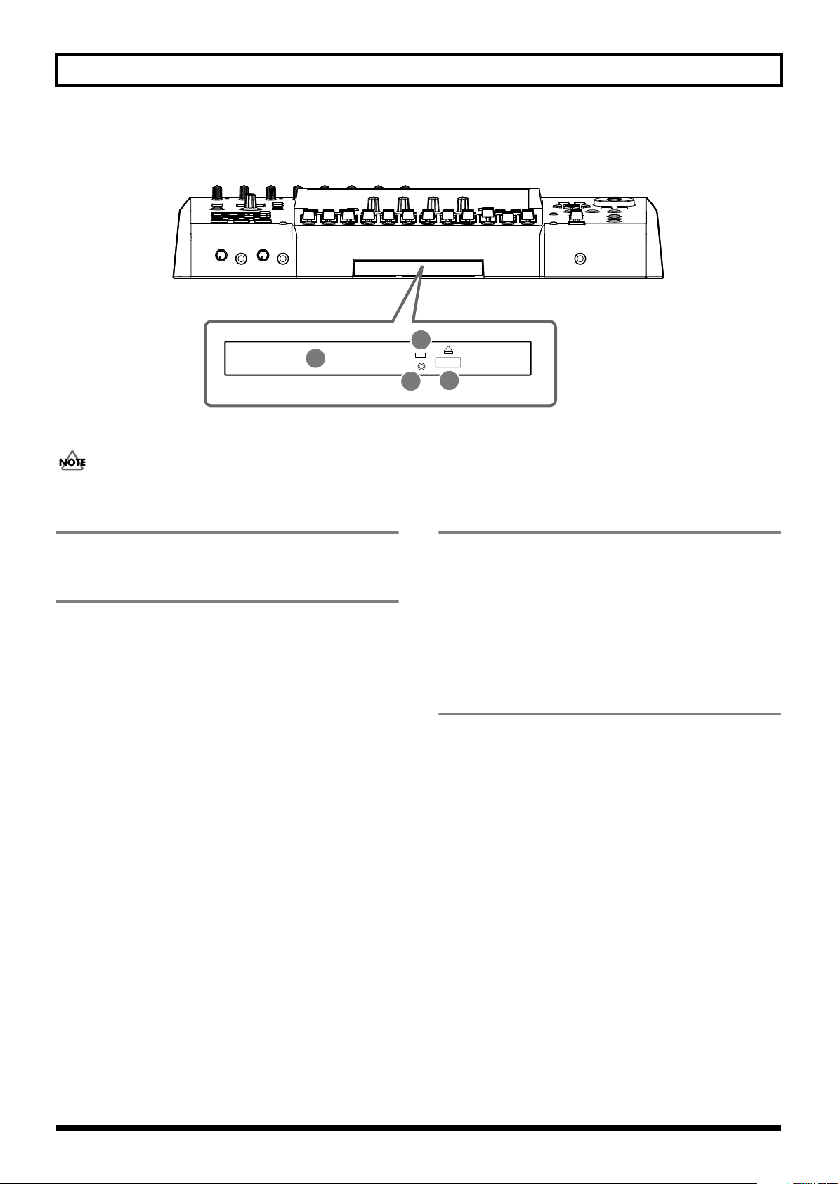
Panel Descriptions
CD-R/RW drive
fig.05-02
2
1
3
4
The BR-1600CD uses this drive unit to read from, write to, and play CD-R/RW discs.
Before you use the CD-R/RW drive, it is important that you first of all read “Before Using CD-R/RW Discs” (p. 7).
1. Disc tray
Place the CD-R/RW discs on this tray.
2. Access indicator
This indicator will light up whenever data is being read from
or written to a CD-R/RW disc.
3. EJECT button
Press this button to eject a CD-R/RW disc from the drive
unit. Note that it will only be possible to eject the CD-R/RW
disc while the BR-1600CD is powered up.
If you need to eject the disc after the power has been turned
off, turn the BR-1600CD back on and then press the EJECT
button. If excessive force is used to extract a disc, you risk
causing damage to the drive.
4. Emergency eject hole
This hole is used when the disc tray must be opened in an
emergency.
It must not, therefore, be used on a regular basis and should
be treated as a last resort only when the disc cannot be
ejected in any other way (p. 8).
30
Page 31

Display
fig.05-03
Panel Descriptions
1
7
Displays the menu screen, parameter setting screen, or other information, depending on the type of settings being made.
If the screen content is difficult to see, refer to “Adjusting the display’s contrast” (Basic Operation; p. 10).
1. Song Name
This box displays the name of the currently selected song. If
protection has been turned on for the song (Song Protect: p.
71), the letter “ ” will also be displayed.
2. Metronome icon
This icon is displayed when the metronome is being used.
3 4 5 6 2
8
9
6. Frames
This box displays the current position in terms of the number
of frames. At the time of purchase, the number of frames per
second will initially be set to 30 (non-drop). This represents
one type of MIDI Time Code (MTC) specification, and if you
want to operate the BR-1600CD and other MIDI devices in
synchrony with each other, all must be set to the exact same
MTC specification.
3. Marker
This box displays the number of the marker at the current
position. If no marker has been placed at this position, the
number of the last marker before the current position is
shown. If, however, the current position is in front of Marker
No. 001 or if no markers have been registered, “- - -” will be
displayed here.
4. Measure
This box displays the current position in the song in terms of
measures and beats. The measures are shown on the left; the
beats, on the right.
5. Time
This box displays the current position in terms of hours,
minutes, and seconds.
“Synchronizing external MIDI sequencers and rhythm
machines” (p. 225)
7. Information
The Information box displays various items of song data
(such as effect patch, marker names, tempo, chord, and the
remaining time available for recording).
8. Input/Track level meters
This area provides a graphic display of the volume levels,
both of instruments connected to input jacks and of recorded
tracks. At the time of purchase, these level meters will be set
to show the volume levels after the corresponding audio has
passed through the INPUT LEVEL knob or the track faders
(i.e., the post-fader volume levels).
If you would like the level meters to show the volumes
before passing through the faders (i.e., the pre-fader volume
levels), refer to “Changing the content of the level meter
display (Pre/Post Fader)” (p. 263).
9. Master level meter
This level meter provides a graphic display of the overall
stereo volume after audio has passed through the MASTER
fader.
31
Page 32

Panel Descriptions
Rear Panel
fig.05-04
1
2
3
4 6 95
10
7
8
1314
1. POWER switch
Use this switch to turn the BR-1600CD on and off (Basic
Operation; p. 8).
2. DC IN (AC adaptor) jack
Connect the BR-1600CD’s AC adaptor to this jack.
In order to prevent accidents, avoid using any AC adaptor
other than the AC adaptor supplied with this unit.
3. Cord hook
Loop the AC adaptor’s cord around this hook in order to
prevent its plug from being pulled out accidentally. If the AC
adaptor should be disconnected while you are using the BR1600CD, there is a danger of important audio data being
permanently lost.
4. MIDI IN connector
The BR-1600CD receives MIDI data via this connector.
Connect the MIDI OUT connector of external MIDI devices
such as sequencers to this connector using a MIDI cable.
“MIDI connectors” (p. 36)
“Section 5 Using MIDI” (p. 221)
5. MIDI OUT connector
11 12
6. USB connector
Plug a USB cable into this connector when you want to
exchange data between the BR-1600CD and a PC.
“USB connector” (p. 37)
“Section 6 Using USB” (p. 239)
7. DIGITAL IN connector
This coaxial-type connector is used to input digital audio
signals into the BR-1600CD. Connect it the digital output of a
BOSS GT-8, a CD player, or another similar device to allow
digital audio to be input.
“DIGITAL IN connector” (p. 35)
“Inputting audio with no loss of quality (Digital In
Assign)” (p. 261)
8. DIGITAL OUT connector
This coaxial-type connector is used to output digital audio
signals from the BR-1600CD, and its output is identical to
that of the LINE OUT jack. You can use the DIGITAL OUT
connector to record the BR-1600CD’s output on CD-R or MD
recorders. In addition, it can also be used to make
connections with amplifiers, speakers, and other devices
with digital inputs.
The BR-1600CD transmits MIDI data via this connector.
Connect the MIDI IN connector of external MIDI devices
such as rhythm machines, sequencers, and sound modules to
this connector using a MIDI cable.
“MIDI connectors” (p. 36)
“Section 5 Using MIDI” (p. 221)
32
“DIGITAL OUT connector” (p. 36)
Page 33

Panel Descriptions
9. FOOT SW jack
Use this jack to connect a separately sold foot switch (such as
the Roland DP-2 or BOSS FS-5U). With a foot switch
connected, you can use it to carry out remote-control
operations such as the start and stop of playback or punchin/out.
“Using a foot switch” (Basic Operation; p. 12)
10. EXP PEDAL jack
Use this jack to connect a separately sold expression pedal
(such as the Roland EV-5 or BOSS FV-500L/FV-500H). When
connected, an expression pedal allows you to use the internal
effects processor’s pedal wah and other similar effects.
“Using an expression pedal” (p. 84)
11. LINE OUT jacks
The LINE OUT jacks are used to output an analog audio
signal. Connect these jacks to a device such as a CD-R, MD,
or tape recorder to make an analog recording of the BR1600CD’s output.
12. INPUT/MIC jacks (1 through 8)
These input jacks and connectors are used with line sources
and microphones. Each input can accept two different types
of connections—namely, an unbalanced connection using the
1/4” phone mono jack, and a balanced connection using the
XLR connector. In addition, phantom power at +48 V can be
supplied via the XLR connectors.
“Using condenser microphones (Phantom Power)” (p. 264)
• If a connection is made to both the 1/4” phone mono
jack and the XLR connector, priority will be given to the
1/4” phone mono jack.
• The INPUT 1/MIC 1 jack (or XLR connector) and the
GUITAR/BASS jack share the same internal circuitry,
and when a connection has been made to both of these
input jacks, the GUITAR/BASS jack will be selected
automatically.
13. Security Slot ( SECURITY LOCK)
http://www.kensington.com/
“LINE OUT jacks” (p. 36)
If necessary, you can make a setting that mixes the
signals being input via INPUT 7/MIC 7 and INPUT 8/
MIC 8 with the signal being output via the LINE OUT
jacks. (Audio Sub Mix: p. 266)
Depending on the circumstances of a particular setup,
you may experience a discomforting sensation, or
perceive that the surface feels gritty to the touch when
you touch this device, microphones connected to it, or
the metal portions of other objects, such as guitars.
This is due to an infinitesimal electrical charge, which is
absolutely harmless. However, if you are concerned
about this, connect the ground terminal (see figure )
with an external ground. When the unit is grounded, a
slight hum may occur, depending on the particulars of
your installation.
If you are unsure of the connection method, contact the
nearest Roland Service Center, or an authorized Roland
distributor, as listed on the “Information” sheet.
Unsuitable places for connection
• Water pipes (may result in shock or electrocution)
• Gas pipes (may result in fire or explosion)
• Telephone-line ground or lightning rod (may be
dangerous in the event of lightning)
14
33
Page 34

Panel Descriptions
Front Panel
fig.05-05
4
5
3
1. GUITAR/BASS jack
This high-impedance input jack is used to directly connect
guitar or bass.
The INPUT 1/MIC 1 jack (or XLR connector) and the
GUITAR/BASS jack share the same internal circuitry,
and when a connection has been made to both of these
input jacks, the GUITAR/BASS jack will be selected
automatically.
2. PHONES 1 jack
Use this jack to connect separately sold headphones.
3. PHONES 1 VOLUME knob
Adjusts the volume for headphones connected to the
PHONES 1 jack.
12
4. PHONES 2 jack
Use this jack to connect a second set of separately sold
headphones.
5. PHONES 2 VOLUME knob
Adjusts the volume for headphones connected to the
PHONES 2 jack.
34
Page 35

Extra information on jacks and connectors
Input jacks and connectors
These jacks and connectors are used to input audio to the BR1600CD.
GUITAR/BASS jack
This high-impedance input jack (1/4” phone plug type) is
used to directly connect guitar or bass.
You can use this jack whenever INPUT SELECT [GUITAR/
BASS], [MULTI-TRACK], or [STEREO TRACKS] is currently
turned on. Note that this input uses the same internal
circuitry as the INPUT 1/MIC 1 jack and its volume can be
adjusted using the INPUT SENS 1 knob. When an instrument
is connected to the GUITAR/BASS jack, this input source
will be given priority and the INPUT 1/MIC 1 jack will be
deactivated. If you want to use the BR-1600CD’s guitar bank
effects as an insert effect for a guitar or bass, connect the
instrument to this jack, and then press INPUT SELECT
[GUITAR/BASS].
When a guitar or bass is connected, noise may be
generated if its pickup is moved close to the BR-1600CD.
In addition, a similar type of noise can also occur if the
instrument is located close to fluorescent lights, a CRT, a
PC, or any other type of electronic device. This noise
occurs when the instrument picks up magnetic noise
generated in electronic devices via its pickup, and if it
becomes noticeable, move the pickup away from the
electronic device.
INPUT 2/MIC 2 jack
These inputs (1/4” phone plug and XLR connector types) are
used with line sources and microphones. The 1/4” phone
plug type jack is used to input unbalanced signals; the XLR
type connector, to input balanced signals. In addition, the
XLR connector can also supply phantom power.
You can use this input whenever INPUT SELECT [VOCAL],
[MULTI-TRACK], or [STEREO TRACKS] is currently turned on.
If you want to use the BR-1600CD’s MIC bank effects as an
insert effect for a vocal mic, connect the microphone to this
input, and then press [VOCAL] from INPUT SELECT.
INPUT 3/MIC 3 jack through INPUT 8/MIC 8 jack
These inputs (1/4” phone plug and XLR connector types) are
used with line sources and microphones. The 1/4” phone
plug type jack is used to input unbalanced signals; the XLR
type connector, to input balanced signals. In addition, the
XLR connector can also supply phantom power.
You can use this input whenever INPUT SELECT [MULTITRACK] or [STEREO TRACKS] is currently turned on.
Note that the INPUT 7/MIC 7 and INPUT 8/MIC 8 jacks can
also be used to input audio signals for an Audio Sub Mix.
Whenever Audio Sub Mix is turned on, the audio signals
being input via the INPUT 7/MIC 7 and INPUT 8/MIC 8
jacks will be output directly via the MASTER track L/R.
“Mixing audio-device output with the BR-1600CD’s
output (Audio Sub Mix)” (p. 266)
INPUT 1/MIC 1 jack
These inputs (1/4” phone plug and XLR connector types) are
used with line sources and microphones. The 1/4” phone
plug-type jack is used to input unbalanced signals; the XLR
type connector, to input balanced signals. In addition, the
XLR connector can also supply phantom power.
You can use this input whenever INPUT SELECT [GUITAR/
BASS], [MULTI-TRACK], or [STEREO TRACKS] is currently
turned on.
Note that this input uses the same internal circuitry as the
GUITAR/BASS jack, and when an instrument is connected to
the GUITAR/BASS jack, that input source will be given
priority and the INPUT 1/MIC 1 jack will be deactivated.
DIGITAL IN connector
This coaxial-type connector is used to input digital audio to
the BR-1600CD. Connect the digital audio output of a CD
player, BOSS GT-8, or BOSS GS-10 to this connector if you
want to record from that device with no deterioration of
sound quality as would occur in analog lines.
Only digital audio data of the S/PDIF format can be input via this
connector; furthermore, the data must have a sample rate of 44.1
kHz and a bit depth of 16 or 24 bits. The destination for audio
entering via the DIGITAL IN connector is determined by system
parameter settings. Note that the INPUT SENS knobs cannot be
used to adjust the volume of the audio being input via this
connector. To do this, either adjust the volume of the digital device
providing the audio signal or use the BR-1600CD’s INPUT LEVEL
knob or LEVEL CALIBRATION function.
It is important to note that standard audio cables cannot be
used with the DIGITAL IN connector and that a
commercially available digital-audio cable or video cable
should be used for this purpose.
35
Page 36

Extra information on jacks and connectors
Output jacks and connectors
These jacks and connectors are used to output audio from the
BR-1600CD.
LINE OUT jacks
The LINE OUT jacks (stereo RCA phono plug type) are used
to output audio in stereo and at line level. The BR-1600CD’s
playback audio, performance of drum, bass, Loop Phrase,
and monitored input will all be mixed into this output signal.
In addition, playback from the CD-R/RW drive built into the
BR-1600CD will also be output here. Use the LINE OUT jacks
to make connections with external audio amplifiers.
Note that the audio output via the LINE OUT jack is also
output via the PHONES 1 jack.
DIGITAL OUT connector
This coaxial-type connector is used to output digital audio
signals, and its output is identical to that of the LINE OUT
jack.
Since digital signals do not suffer from the same type of
deterioration as occurs in analog lines, they can be recorded
without degradation in the quality of your audio on external
digital audio devices such as CD-R, MD, and DAT recorders.
In addition, if you are using Roland DS-30A Bi-Amp Monitor
to monitor your sound, audio signals can be output to the
speakers via this connector.
It is important to note that standard audio cables cannot be
used with the DIGITAL OUT connector and that a
commercially available digital-audio cable or video cable
should be used for this purpose.
MIDI connectors
The BR-1600CD features both MIDI OUT and MIDI IN
connectors in order that MIDI data may be transmitted and
received.
MIDI IN connector
This 5-pin DIN type connector is used to receive MIDI data
from other MIDI devices such as rhythm machines and
sequencers. Connect the MIDI OUT connector of the external
device to this connector using a MIDI cable.
MIDI OUT connector
This 5-pin DIN type connector is used to transmit MIDI data
from the BR-1600CD. Connect the MIDI IN connector of
external MIDI devices such as rhythm machines, sequencers,
and sound modules to this connector using a MIDI cable.
In order to ensure that the BR-1600CD operates correctly,
do not create such a loop by, for example, connecting a
single MIDI cable between its MIDI IN and MIDI OUT
connectors. A MIDI loop is created when MIDI data
transmitted from a MIDI OUT connector is returned
without modification to the MIDI IN connector in the
same system, and this can cause devices to operate
abnormally.
PHONES 1 and PHONES 2 jack
Allow you to connect a pair of headphones (with a 1/4”
phone stereo plug).
36
Page 37

Extra information on jacks and connectors
USB connector
This B-type connector is used to connect with a host
computer. (USB: Universal Serial Bus)
The BR-1600CD is compatible with USB version 1.1. By
connecting it with the USB connector of a PC using a
commercially available USB cable, you can transfer song
data, .wav files and other similar information between the
PC and the BR-1600CD. In addition, this also allows you to
backup song data and the like on your PC’s hard disk.
“Section 6 Using USB” (p. 239)
When a connection is made using USB, you will be able
to access the data on the BR-1600CD’s hard disk from
your PC. Accordingly, there is an increased danger of
accidentally damaging or deleting the BR-1600CD data.
Extra special care must be taken in such a situation as
data damaged or lost in this way cannot be restored.
Please also note that BOSS/Roland will accept no
responsibility for the repair of damaged data or for
compensation for lost or damaged data.
The BR-1600CD can be used neither as a USB host nor a
USB hub. As a result, you will not be able to use the USB
connector to access external hard disks, CD-R/RW
drives, or other similar types of USB device.
Furthermore, this USB connector cannot be used with an
audio interface or the like.
Power supply
DC IN (AC adaptor) jack
Connect the BR-1600CD’s AC adaptor to this jack.
In order to prevent accidents, avoid using any AC
adaptor other than the AC adaptor supplied with this
unit. Failure to observe this precaution can result in the
outbreak of fire or electrical shock. Note also that usage
of any other type of AC adaptor can result in the
permanent damage of the BR-1600CD itself, the hard
disk, or the CD-R/RW drive. It is important, therefore,
that the appropriate care be taken.
If you disconnect the AC adaptor while the BR-1600CD
is reading from or writing to its hard disk (i.e., when the
HD ACCESS indicator is lit), the hard disk will be
irrepairably damaged. If a hard disk is damaged in this
way, you will be no longer able to use it for recording,
playback, song saving, or song loading; furthermore,
there is a high probability that valuable data will be lost.
Be sure, therefore, to loop the AC adaptor’s cord around
the cord hook to prevent it being accidentally pulled out
during operation of the BR-1600CD.
37
Page 38

Common operations and display items
Marker number
Measure
Beat
Hour Frame
minute
Second Sub Frame
Cursor
Top screen
fig.06-01d
Tempo
Name of Mark at Current Position
Selected Effect Patch Name
Song Name Current Position
Remaining Recording Time
Chord
Level Meters
Displayed shortly after the power is turned on, this is the
main BR-1600CD screen. Among other important
information, the top screen presents the name of the
currently selected song, the current position within the song,
the level meters, and remaining recording time on the hard
disk.
Regardless of the screen that you are currently in, you will
always be able to return to this screen by pressing [EXIT/
NO] several times (although you may sometimes have to
wait until the BR-1600CD completes the current process).
Unless otherwise specified, all procedures described in this
manual will require you to return first of all to the top screen.
Mastering Mode Top Screen
Current position
fig.06-02d
In Mastering mode only, the top screen changes to the screen
like that shown to the left.
The current position within the song is indicated in terms of
time at the top right of the display. In addition, this position
is also indicated in terms of measures and beats to the left of
this time value.
The displayed time is based on MIDI Time Code (MTC), and
as such, it is presented in terms of hours, minutes, seconds,
frames, and sub-frames. Note that different devices use
different MTC specifications.
If you want to synchronize the BR-1600CD with another
MIDI device using MTC, you will first of all need to set both
to the same MTC specification. At the time of purchase, the
number of frames per second will initially be set to 30 (nondrop) on the BR-1600CD. (p. 227)
FUNCTION buttons ([F1] through [F4])
fig.06-04
38
Function buttons
[F1] through [F4] are called the FUNCTION buttons. At the
bottom of the display, you will find the names of the
functions that are assigned within the current screen to each
of these buttons.
If an explanation from this manual were to refer to “[F1]
(WRITE)”, you would know that pressing [F1] would select
the “WRITE” function as displayed immediately above the
button.
Page 39

PAGE SCROLL buttons
fig.06-06
Common operations and display items
When “ ” and/or “ ” is displayed on the left and right of
the screen, respectively, it will indicate that the BR-1600CD
could not fit all of the relevant content on-screen and that
some content is hidden in the direction of the arrow. The
PAGE SCROLL buttons [ ] and [ ] are used to
display this hidden content. Press [ ] to scroll the screen
to the left, and press [ ] to scroll the screen to the right.
Although you can also scroll the screen by holding down
Scroll Bar
fig.06-01d
Cursor
fig.06-03
(Left) (Right)
Page scroll buttons(Left) (Right)
Scroll bar
(Up)
(Down)
[ ] or [ ] from CURSOR, this can be done much quicker
using the PAGE SCROLL buttons.
When you see a scroll bar at the right of the screen, it means
that the BR-1600CD could not fit all of the relevant content in
one screen, and there is additional content hidden at the top
or the bottom.
The white portion of the scroll bar represents the entire
display content, and the black portion represents the range of
that content that is currently being displayed.
The view the hidden content, press [ ] or [ ] from
CURSOR to move the display area up or down, respectively.
When the display area is moved up, the black area in the
scroll bar will also move up, and when the display area is
moved down, the black area moves down.
The BR-1600CD’s cursor is represented either as an inverted
character, a frame, or an underline in a section of the screen
that allows settings to be made. When represented as a knob
icon, the knob is shown in black.
If the current screen contains a number of such sections, you
can use [CURSOR] to move between the corresponding
setting items.
In addition, when you press and hold down [CURSOR], the
on-screen cursor will move continuously in the
corresponding direction.
If you need to speed up the motion of the cursor, press and
hold the CURSOR arrow for the required direction of
movement, and then press the CURSOR arrow for the
opposite direction. This action will cause the cursor to move
more quickly around the screen.
Example: To move the cursor quickly to the right
Press and hold CURSOR [ ], and then press [ ].
Example: To move the cursor quickly downward
Press and hold CURSOR [ ], and then press [ ].
39
Page 40

Common operations and display items
TIME/VALUE dial
fig.06-05
The TIME/VALUE dial is used to change the cursor position,
values, or characters. In the case of values, these are
increased when the dial is turned clockwise, and reduced
when the dial is turned counterclockwise.
VALUE 1/PAN, VALUE 2, VALUE 3, and VALUE 4 knobs
fig.06-07
These knobs can be used to change the values of parameters
indicated by knob icons ( ) on-screen.
Turn clockwise to increase a value and counterclockwise to
decrease it.
In addition, you can also use these knobs to make large changes in
pattern and loop phrase numbers when a pattern selection screen
for rhythm patterns, bass patterns, or loop phrases is displayed.
40
Page 41

Section 1 Advanced Use
Section 1
Advanced
Use
41
Page 42

Re-recording only the portion that is mistaken (Punch In/Out)
You may occasionally make a mistake during a recording, or
the performance may not turn out the way the musician
intended. In such cases, you can use functions known as
punch in and punch out to re-record specific parts of the
performance. Specifically, punch in refers to an action where
recording is started while listening to playback of a track,
and punch out refers to the reverse situation where recording
is stopped but playback of the track can still be heard. In
other words, you punch in at the start of the section you
want to re-record, and you punch out at the end of that
section.
fig.10-01
Playback PlaybackRecording
Time
Start
[PLAY] [REC] [REC] [STOP]
• If you are still not happy with the track after re-
recording with punch in and punch out, you can use
Undo (Basic Operation; p. 42) to restore the track to its
original condition.
• Even if a portion of a track has been re-recorded using
punch in and punch out, the replaced audio data will
remain on the BR-1600CD’s hard disk. If this data will
not be used again, Song Optimization (p. 70) allows you
to delete it together with other unneeded data, thus
ensuring that you make the most of the hard disk’s
storage capacity.
The BR-1600CD supports two different types of punch in/
out procedures—namely, manual punch in/out and auto
punch in/out.
Punch-in
Punch-out
Stop
Performing manual punch in and punch out using [REC]
The following section will describe using manual punch in
and punch out to re-record a portion of Track 1, which was
recorded earlier.
1.
Press the TRACK [1].
This track button will start to flash orange and green.
2.
Move the fader for Track 1 to the position shown
below.
fig.10-02
3.
Confirm that [ON/OFF] from AUTO PUNCH is not lit
up.
If this button is lit, it will need to be pressed to turn it off.
4.
Start playback of your song and use the INPUT LEVEL
knob to adjust the volume of the input to an
appropriate level.
If you want to mute Track 1 during playback, hold down
[TRACK MUTE] and press the track button for this track.
You can then perform the same procedure once again to
cancel muting.
Listen to both the recorded audio and the input to
compare their volumes. If necessary, use the INPUT
LEVEL knob to adjust the volume of the input so it is
identical to that of the recording.
5.
When the volume levels have been matched, confirm
that Track 1 is not being muted before proceeding.
Manual punch in and punch out
Use [REC] or a foot switch to activate punch in and punch
out. If you are both playing the instrument and operating the
BR-1600CD, it can often be difficult to press [REC] at the
right time. In such a case, a foot switch (such as the optional
Roland DP-2 or BOSS FS-5U) can be used to activate punch
in and punch out conveniently by foot.
42
6.
Move to a position before where you want to start rerecord and press [PLAY] to start playback.
7.
When playback reaches the beginning of this section,
press [REC] to punch in and start recording.
To punch out after recording, press either [REC] or
[PLAY].
[REC] can be used to punch in and punch out
repeatedly, and if any other sections need to be rerecorded, you can use the same procedure described
above without having to stop playback.
8.
Press [STOP] when re-recording has been completed.
9.
Listen to the performance with the re-recorded section.
Make sure that you move the current position to a point
before the re-recorded section before starting playback.
If necessary, use the fader for Track 1 to adjust its
volume.
Page 43

Re-recording only the portion that is mistaken (Punch In/Out)
Performing manual punch in and punch out using a foot switch
If you intend to use a foot switch (such as the optional
Roland DP-2 or BOSS FS-5U) to activate punch in and punch
out, it should be connected to the BR-1600CD at this time.
Use the following procedure to set the appropriate action for
the foot switch jack.
1.
Press [UTILITY].
The Utility Menu screen will appear.
fig.12-12d
2.
Move the cursor to the SYSTEM icon and press
[ENTER/YES].
Alternatively, you can press [F1] (SYSTEM) if the
SYSTEM icon is currently displayed.
The System screen will appear.
fig.10-03d
Auto punch in and punch out
The BR-1600CD supports a function known as Auto Punch In/
Out, which will automatically activate punch in and punch out
at specified locations within a song. This function is extremely
useful in situations where punch in and punch out must be
activated at exactly the right time, and where you need to
concentrate on your performance, not the pressing of buttons.
Specifying the section to be rerecorded
In order to activate punch in and punch out automatically,
you will first of all need to set up the punch in and punch out
positions as described below.
●
Registering the punch in position
1.
Move the current position to the point at which you
want the BR-1600CD to activate punch in and press
AUTO PUNCH IN/OUT [IN].
The current position will now be registered as the
position for punch in, and [IN] will light up to indicate
that a punch in position has been registered.
fig.10-05
Section 1
3.
Move the cursor to “Foot Switch” and select PUNCH
IN/OUT using the TIME/VALUE dial.
fig.10-04d
4.
Press [EXIT/NO] several times to return to the top
screen.
5.
Start the recorder.
6.
Operate the foot switch.
Each time the foot switch is depressed, the BR-1600CD
either punches in or punches out.
* Once a punch in position has been registered, you can jump to
this position at any time by pressing [IN].
* If you want to cancel this position and/or register a new point
for punch in, hold down [DELETE] and press [IN]. The punch
in position will be cleared and [IN] will turn off.
●
Registering the punch out position
2.
Move the current position to the point at which you
want the BR-1600CD to activate punch out and press
AUTO PUNCH IN/OUT [OUT].
The current position will now be registered as the
position for punch out, and [OUT] will light up to
indicate that a punch out position has been registered.
fig.10-06
* Once a punch out position has been registered, you can jump
to this position at any time by pressing [OUT].
43
Page 44

Re-recording only the portion that is mistaken (Punch In/Out)
* If you want to cancel this position and/or register a new point
for punch out, hold down [DELETE] and press [OUT]. The
punch out position will be cleared and [OUT] will turn off.
* Note that the punch in and punch out positions must be at
least 0.5 seconds apart. Accordingly, the punch out position
cannot be set up within 0.5 seconds of the punch in position.
If you want to activate punch in and punch out at
marker positions, first of all move the current position to
the marker for punch in and press [IN]. Then, move to
the marker for punch out and press [OUT]. For a
description of the procedure for moving to marker
positions, refer to “Moving to markers” (p. 48).
Performing auto punch in and punch out
For this example, we will use auto punch in and punch out to
re-record a portion of Track 1, which was recorded earlier.
1.
Press the TRACK [1].
This track button will start to flash orange and green.
2.
Move the fader for Track 1 to the position shown
below.
fig.10-02
3.
Confirm that AUTO PUNCH IN/OUT [ON/OFF] is not lit up.
If this button is lit, it will need to be pressed to turn it off.
4.
Start playback of your song and use the INPUT LEVEL
knob to adjust the volume of the input to an
appropriate level.
5.
When the volume levels have been matched, confirm
that Track 1 is not being muted before proceeding.
6.
Move to a position before where you want to start rerecord and press AUTO PUNCH IN/OUT [ON/OFF].
This button will light up to indicate that auto punch in/
out has been turned on.
7.
Press [REC] to prepare the BR-1600CD for recording
and then press [PLAY].
Punch in will be activated automatically at the beginning
of the section to be re-recorded so that you can perform
your part without having to worry about pressing
buttons. Similarly, when the end of this section has been
reached, the BR-1600CD will automatically activate
punch out and continue normal playback.
8.
Press [STOP] when re-recording has been completed.
9.
Listen to the performance with the re-recorded section.
Make sure that you move the current position to a point
before the re-recorded section before starting playback.
If necessary, use the fader for Track 1 to adjust its
volume. You can press [IN] at this time to jump straight
to the punch in position.
44
10.
To clear the settings for the auto punch in/out section,
hold down [DELETE], press [IN] or [OUT].
Page 45

Re-recording only the portion that is mistaken (Punch In/Out)
Repeating recording in a specific section (Loop Recording)
When the BR-1600CD’s repeat function is used in
combination with punch in and punch out, the recorded
section will be played back automatically so you can hear
what you have recorded. In addition, if you find that you are
not happy with your recording, simply press [REC] without
stopping playback to re-record once again. The combination
of auto punch in/out with the repeat function in this way is
referred to as Loop Recording.
For more detailed information regarding the repeat
function, refer to “Playing back repeatedly (Repeat
Function)” (Basic Operation; p. 17).
Specifying the section to be repeated
Before you start recording, you will first of all have to set up
the start and end points of the section to be repeated.
At this time, it is important that you set up the section in
such a way that it contains the section to be re-recorded (i.e.,
the section between the punch in and punch out positions). If
the repeat section does not fully enclose the re-record section,
recording may not start as required at the specified position
or it may end abruptly in the middle of the re- record section.
fig.10-07
Repeat
Recording
Repeat Start
(A)
Punch-in Punch-out Repeat end
Specifying the section to be recorded
Use “Auto punch in and punch out” (p. 43) to register the
positions where the punch-in and punch-out are to be
performed.
PlaybackPlayback
Time
(B)
Performing loop recording
As an example, the following section will describe usage of
the repeat function together with auto punch in and punch
out to re-record a portion of Track 1, which was recorded
earlier.
1.
Press the TRACK [1].
This track button will start to flash orange and green.
2.
Move the fader for Track 1 to the position shown
below.
fig.10-02
3.
Press AUTO PUNCH IN/OUT [ON/OFF].
This button will light up to indicate that auto punch in/
out has been turned on.
4.
Start playback of your song using the repeat function
and use the INPUT LEVEL knob to adjust the volume
of the input to a suitable level.
5.
With repeat playback in progress, press [REC] just
before the punch-in position.
The BR-1600CD automatically switches to record mode
at the punch-in position; recording stops automatically
at the punch-out position, and the BR-1600CD reverts to
playback mode.
After repeating, confirm the results just recorded.
If you were unable to get the recording to sound the way
you wanted, press [REC] and record the passage over
again.
If you press [REC] within the segment between the
punch-in and punch-out positions, the BR-1600CD
immediately switches to record mode at that point, then
automatically stops recording at the punch-out position.
6.
Press [STOP] when re-recording has been completed.
Press [REPEAT]. This button will turn off, indicating that
playback will not be repeated.
Section 1
7.
Press AUTO PUNCH IN/OUT [ON/OFF].
This button will turn off, indicating that the auto punch
in/out has been deactivated.
45
Page 46

Using V-Tracks
Although the BR-1600CD is a 16-track multi-track recorder,
you can select any one of sixteen V-Tracks for each of these
tracks. In this way, you can use the BR-1600CD as if it were
actually a 256-track multi-track recorder. In other words, V-
Tracks can be used to make multiple recordings of guitar
solos, vocals, etc. without having to delete any of these takes,
and this ensures that the best performance can be selected
later on. What’s more, you can also choose the best parts
from takes on a number of different V-Tracks and combine
them onto a single track.
“Editing a recorded performance (Track Edit)” (p. 56)
Switching V-Tracks
1.
Press [V-TRACK].
The V-Track screen will appear.
fig.11-01d
The currently selected track is shown on the top left of the
display, together with the number of the V-Track that is
selected for it. In addition, the name of the currently
selected V-Track is shown on the middle left of the display.
( ): Currently selected V-Track (containing
recorded audio data)
( ): Currently selected V-Track (not containing
recorded audio data)
( ): V-Track containing recorded audio data
( ): V-Track not containing recorded audio data
( ): The V-Track from Track 9/10 last used for
mastering (Final Mastering Track)
2.
Move the cursor to the track containing the V-Track
you want to change.
fig.11-02d
In addition to the cursor, the track buttons can also be used to
directly choose the track whose settings are to be changed.
3.
Use the TIME/VALUE dial to change the V-Track setting.
The “ ” is displayed when the V-Track containing
recorded audio data is selected.
fig.11-03d
4.
When you have finished selecting V-Tracks, press
[EXIT/NO] to return to the top screen.
5.
If you wish to store the currently selected V-Tracks,
save the current song (p. 72).
• If V-Tracks are changed during playback, this
playback will be interrupted momentarily. Note,
however, that this is normal and does not indicate a
malfunction.
• You cannot use the track buttons in the V-Track
screen to select tracks to be recorded.
46
Page 47

Using V-Tracks
Assigning names to V-Tracks (Track Name)
Names can be assigned to any or all of the BR-1600CD’s 256
V-Tracks. Although a name corresponding to the Input Select
(i.e., Track Name) used for a V-Track is assigned
automatically when it is initially recorded to, you can easily
edit this name later on.
1.
Press [V-TRACK].
The V-Track screen will appear.
fig.11-01d
2.
Use [CURSOR] and the TIME/VALUE dial to choose
the V-Track that you are going to name.
fig.11-05d
Changing the V-Track to be written to an audio CD (the Final Mastering Track)
When in Mastering mode, the symbol [ ] will be
automatically placed on the right of the V-Track from Track
9/10 that was most recently used for mastering. This V-Track
is referred to as the Final Mastering Track. This V-Track is
automatically selected for writing to a CD-R/RW disc during
the creation of an audio CD, and you can speed up the entire
process by setting the final mastering track correctly.
For more detailed information regarding mastering,
refer to “Adjusting volume and compression for CD
writing (Mastering Tool Kit)” (Basic Operation; p. 58).
Although the final mastering track is set automatically when
mastering is carried out, you can change this to any other V-
Track later on. Use the following procedure to do so.
1.
Press [V-TRACK].
The V-Track screen will appear.
fig.11-07d
Section 1
In addition to the cursor, the TRACK buttons can also be
used to directly choose the track selected.
The name of the currently selected V-Track is shown on
the middle left of the display.
3.
Move the cursor to the letter in the name that you want
to change, and then use the TIME/VALUE dial to select
a new letter.
fig.11-06d
4.
When you have finished editing names, press [EXIT/
NO] to return to the top screen.
5.
If you wish to store the edited names, save the current
song (p. 72).
2.
Move the cursor to the “MASTER V-TRACK,” and
then use the TIME/VALUE dial to select the final
mastering track.
fig.11-08d
3.
If you wish to store the new setting for the final
mastering track, save the current song (p. 72).
Only V-Tracks from Track 9/10 can be set as the
final mastering track.
47
Page 48

Placing markers in your song (Marker)
The BR-1600CD’s Marker function allows you to place
markers at the required points in a song. You can then jump
quickly to any registered marker position by simply
indicating its number. In addition, this function also proves
extremely useful during the editing process. Up to 100
markers can be positioned within a song, and these are
numbered 1 to 100 from the beginning of the song. For this
reason, whenever a new marker is positioned between two
pre-existing markers, the number of all subsequent markers
will increase by one. For example, numbers will change as
follows when a new marker is inserted after Marker No. 2.
fig.12-01
Marker 1Marker
Marker 1Marker 2Marker
In addition, you can also assign names to individual markers.
For more detailed information, refer to “Naming a marker”
(p. 49).
2
Marker 3Marker
3
Marker 4Marker
4
Time
5
Time
Basic marker operations
Positioning a marker
Press [MARK] to place a marker at the current song position.
fig.12-02
Note that markers must be at least 0.1 seconds apart.
Accordingly, it will not be possible to position a new
marker within 0.1 seconds of a pre-existing marker.
Clearing markers
The marker box of the display will indicate the marker
located earlier than the current position.
Press [CLEAR] if you want to delete this marker.
fig.12-03
Moving to markers
Use the SEARCH buttons to move forwards or backwards to
the next nearest marker. Alternatively, if you press the
CURSOR [ ] while on the following screen (i.e., the top
screen), you will be able to change the marker number
shown in the display’s Marker box.
fig.12-04
Marker number
Use the TIME/VALUE dial to select the number of the
marker you want to move to.
48
Page 49

Placing markers in your song (Marker)
Editing markers
Moving markers
1.
Press [UTILITY].
The Utility Menu screen will appear.
fig.12-12d
2.
Move the cursor to the MARKER icon and press
[ENTER/YES].
If the MARKER icon is not currently being shown on the
display, use the [ ] and [ ] PAGE SCROLL
buttons to move to the page containing this icon.
The Marker screen will appear.
fig.12-05d
Naming a marker
A name (Marker Name) can be assigned to any marker from
the Marker screen.
1.
On the Marker screen, move the cursor to “No.” and
then use the TIME/VALUE dial to select the number of
the marker to be named.
fig.12-08d
2.
Move the cursor to “Name”, and then use [CURSOR]
and the TIME/VALUE dial to change the marker name.
fig.12-09d
Assigning an audio-CD song division to a marker
Section 1
3.
Use the TIME/VALUE dial to select the number of the
marker you want to edit.
fig.12-06d
4.
Move the cursor to “Location”, and then use the TIME/
VALUE dial to specify a position for that marker.
fig.12-07d
Measure Time
If you move the cursor to the measure display, you will
be able to specify a marker position in terms of
measures. Alternatively, you can move the cursor to the
time display to move the marker based on the song time.
When writing stereo tracks to an audio CD, you can use a
special procedure to position markers within a track so that
these markers can indicate the song division points on the
finished CD. This method of creating audio CDs is referred
to as Disc At Once By Marker.
For more detailed information regarding Disc At Once By
Marker, refer to “Dividing long tracks and writing as multiple
songs (Disc At Once By Marker)” (Basic Operation; p. 66).
When on the Marker screen, even normal markers that you have
already positioned can be designated as song division markers.
1.
On the Marker screen, move the cursor to “No.” and
then use the TIME/VALUE dial to select the number of
the marker to be designated as a song division.
2.
Move the cursor to “CD Track” and select “ON” using
the TIME/VALUE dial.
fig.12-10d
The selected marker will be designated as a song
division marker for the audio CD. At the same time, the
name to be displayed for the corresponding song on the
audio CD (i.e., CD01 to CD99) is automatically set as the
marker name.
49
Page 50

Placing markers in your song (Marker)
Note that if a marker that has already been named is
designated as a song division marker, the original name
will be deleted.
3.
Save the current song (p. 72).
• Be sure to save your song before creating an audio
CD. Settings will not be stored until your song is
saved, and this can result in song divisions not being
recognized correctly during the writing process.
• A maximum of 99 songs can be written to a single
audio CD. If you try to set a song division marker
that will result in this number being exceeded, the
message “Marker Memory Full!” will be displayed
and you won’t be able to set it.
• Audio CD standards require that a CD track be at
least four second long. CD track markers that define
a CD track lasting less than four seconds are
disregarded when the CD is being created.
Stopping automatically at a marker (Marker Stop)
The BR-1600CD can be made to automatically stop recording
or playback at marker positions. If the operation (i.e.,
recording or playback) is then restarted, it will continue to
the next marker, where it will again be stopped
automatically.
1.
Press [UTILITY].
The Utility Menu screen will appear.
fig.12-12d
2.
Move the cursor to the SYSTEM icon and press
[ENTER/YES].
Alternatively, you can press [F1] (SYSTEM) if the
SYSTEM icon is currently displayed.
The System screen will appear.
fig.10-03d
Changing scenes assigned to markers
The BR-1600CD allows you to assign scenes to markers so
that they can be recalled automatically during playback. This
operation is referred to as Auto Scene.
For more detailed information regarding Auto Scene,
refer to “Recalling scenes automatically during
recording or playback (Auto Scene)” (p. 52).
The allocation of scenes to markers can be modified from the
Marker screen at any time.
1.
On the Marker screen, move the cursor to “No.” and
then use the TIME/VALUE dial to select the number of
the marker in question.
2.
Move the cursor to “Scene” and select the number of the
scene to be assigned using the TIME/VALUE dial.
fig.12-11d
The selected scene will be assigned to the marker.
3.
Move the cursor to “Marker Stop” and select “ON”
using the TIME/VALUE dial.
fig.12-14d
If you set this to “OFF”, the Marker Stop function will be
deactivated.
3.
If you wish to store the modified settings, save the
current song (p. 72).
If you do not save the song, your settings will not be stored.
50
Page 51

Registering and recalling mixer settings (Scene)
The BR-1600CD allows you to register up to 100 batches of
mixer and effect settings per song. Each of these batches of
settings is referred to as a Scene, and they can be quickly and
easily recalled whenever needed.
For example, if you wish to compare different mix balances
during mixdown, it is convenience to register each of the
different mixer setting as a scene.
In addition, you can also assign scenes to markers (p. 48) to
have them recalled automatically during recording or
playback, and this function is referred to as Auto Scene.
Registering, recalling, and deleting scenes
1.
Press [UTILITY].
The Utility Menu screen will appear.
fig.12-12d
To delete:
Press [F2] (DELETE).
The asterisk (*) indicating a registered scene will
disappear to show that the scene is no longer registered.
5.
Press [EXIT/NO] several times to return to the top screen.
6.
If you wish to store the scene settings, save the current
song (p. 72).
Recalling a scene without changing track volumes
When you recall a scene, the track volumes change to the
levels stored in that scene, but the positions of the faders
remain the same. As a result, fader positions and actual
volumes will no longer match. However, the following
procedure can be used in situations where you want to recall
a scene without changing the track volumes from those
matching the current fader positions.
1.
Move to the Scene screen.
Section 1
2.
Move the cursor to the SCENE icon and press [ENTER/YES].
Alternatively, you can press [F3] (SCENE) if the SCENE
icon is currently displayed.
The Scene screen will appear.
fig.13-02d
3.
Use the TIME/VALUE dial to select the number of the
scene to be registered, recalled, or deleted.
fig.13-03d
If you select the number of a scene that has already been
registered, an asterisk (*) will be displayed before the
number to inform you of this fact.
4.
Register, recall, or delete a scene.
To recall:
Press [F4] (CALL).
To register:
Press [F3] (SAVE).
An asterisk (*) indicates that a scene has already been
registered. If you select such a scene, it will be
overwritten using the current settings.
2.
Move the cursor to “Track Level” and select “FADER”
using the TIME/VALUE dial.
fig.13-04d
Track Level
This setting determines how track volumes will be
treated when a scene is recalled.
SCENE:
When a scene is recalled, the track volumes will change
to the levels stored in that scene. As a result, it is quite
possible that the front panel’s fader positions will no
longer match the actual track volumes.
FADER:
Even if a scene is recalled, the track volumes will stay at
the levels matching the positions of the front panel’s
faders.
3.
Press [EXIT/NO] several times to return to the top screen.
4.
If you wish to store the modified settings, save the
current song (p. 72).
If you do not save the song, your settings will not be
stored.
51
Page 52

Recalling scenes automatically during recording or playback (Auto Scene)
The BR-1600CD allows you to assign scenes to markers so
that they can be recalled automatically when recording or
playback reaches the corresponding marker positions.
Referred to as Auto Scene, this function makes it possible for
track faders, effects, etc. to be controlled automatically.
Setting an Auto Scene
1.
With the top screen displayed, move to the position in the
song where you want settings to be changed automatically.
2.
Hold down [STOP] and press [MARK].
A new marker will be created at the current position.
Also at this time, a new scene will be created and
assigned to the marker. All settings for track faders,
effects, and the like will be stored in this scene.
In addition, an “S” will appear in the Marker name area
on the top screen to indicate that a scene has been
assigned to the marker.
fig.13-05
3.
Press [ZERO] to return to the beginning of the song and
then press [PLAY] to start playback.
When playback reaches the position of the new marker,
the scene that you have assigned to it will be
automatically recalled. In addition, an “S” will appear in
the top screen’s Marker name area.
Automatic recalling of scenes is not restricted to
playback and recording; in fact, scenes are recalled
automatically whenever the current position is moved to
the position of the corresponding marker, even if
playback is stopped at the time. It is important to note
that not all parameter settings stored in a scene will be
restored when it is recalled automatically. Settings are
restored for the following parameters.
• Faders for Tracks 1 through 15/16
• Track mute
• The MASTER fader
• Pan (for Tracks 1 through 15/16)
• Compressors and limiters
• EQ (for Tracks 1 through 15/16) (p. 74)
• Insert effects (p. 74), Vocal Tool Box (p. 75), Speaker
Modeling (p. 75), Mastering Tool Kit (p. 75)
• Chorus/delay sends (for Tracks 1 through 15/16)
• Reverb sends (for Tracks 1 through 15/16)
* Settings can be made to indicate whether or not EQ and effect
parameters will be restored by Auto Scene (p. 53). This is set
to OFF in the factory settings.
4.
If you wish to store the modified settings, save the
current song (p. 72).
The allocation of scenes to markers for Auto Scene
can be modified later on. For more detailed
information regarding the modification of scene
assignments, refer to “Changing scenes assigned to
markers” (p. 50).
• A maximum of 100 markers can be created in a single song,
and this includes both markers with scenes assigned and
those without. Furthermore, a maximum of 100 scenes can
be registered. If you try to create a marker or scene that will
result in the corresponding limit being exceeded, the
message “Marker Memory Full!” or “Scene Memory Full!”
will be displayed and this action will not be possible.
• When a new marker and scene are created as described
in Step 2, the lowest available number will be assigned to
this new scene.
• Markers cannot be created within 100 ms of one another.
In such instances, first clear the existing marker, and
then carry out Step 2 (p. 48).
• When a scene is recalled, there may be a delay of several
hundredths of a second before the stored settings are
actually applied to your song. Please note that this delay
is intentional and is intended to prevent noise being
generated as a result of sudden changes in parameters.
• If you do not save the song as indicated in Step 4, your
settings will not be stored.
Clearing an Auto Scene
1.
Press MARKER [SEARCH ] or [SEARCH ] to
move to the marker with the scene assignment you
wish to clear.
This marker will be shown in the display’s Marker box.
2.
Press MARKER [CLEAR].
The current marker will be cleared together with the
scene that was assigned to it.
If a scene has also been assigned to some other marker,
the scene itself won’t be erased; only the current marker
will be erased.
52
Page 53

Recalling scenes automatically during recording or playback (Auto Scene)
Disabling Auto Scene
Auto Scene can actually hinder your work in certain
situations if settings are automatically restored while you are
manually operating track faders and the like.
In such cases, use the following procedure to disable Auto
Scene and prevent it from changing your settings.
1.
Press [UTILITY].
The Utility Menu screen will appear.
fig.12-12d
2.
Move the cursor to the SYSTEM icon and press
[ENTER/YES].
Alternatively, you can press [F1] (SYSTEM) if the
SYSTEM icon is currently displayed.
The System screen will appear.
fig.10-03d
Setting Auto Scene control of effects and track EQ
Use the following procedure to allow or forbid the control of
effects (i.e., insert effects, Vocal Tool Box, Speaker Modeling,
and Mastering Tool Kit) and of track EQ by Auto Scene.
1.
Press [UTILITY].
The Utility screen will appear.
2.
Move the cursor to the SYSTEM icon and press
[ENTER/YES].
Alternatively, you can press [F1] (SYSTEM) if the
SYSTEM icon is currently displayed.
The System Parameter screen will appear.
3.
Move the cursor to “Effects” or “Track Equalizer” and
select “ON” or “OFF” using the TIME/VALUE dial.
fig.10-03d
Section 1
3.
Move the cursor to “Auto Scene” and select “OFF”
using the TIME/VALUE dial.
Auto Scene will now be disabled.
fig.13-07d
To enable Auto Scene once again, return the above
setting to “ON.”
4.
If you wish to store the modified settings, save the
current song (p. 72).
Take care not to forget if “Auto Scene” is set to
“OFF” when saving a song, or Auto Scene will not
function afterwards. We recommend returning this
setting to “ON” as often as possible when saving
songs.
ON:
OFF:
4.
If you wish to store the modified settings, save the
current song (p. 72).
• When playback reaches a location where a marker
has been set, the scene assigned to the marker is
called up automatically, and the settings change to
those recorded in the scene, including the track EQ
and effects patch parameters.
• Be sure to note that application of the effects in the
performance may be delayed from several hundred
milliseconds to one second from the point at which
the marker is set.
• Patch switching will be possible for similar types of
effects (for example, patches from insert effects), but
not for different types. In addition, this type of
change will not be possible for different insert effect
connections (p. 82).
• Depending on the sounds used in a performance
recorded on a track, noise may be audible when the
EQ is being adjusted.
Control by Auto Scene is allowed.
Control by Auto Scene is forbidden.
53
Page 54

Finding the start or end of a section of audio (Scrub/Preview)
SCRUB
TO
Time
Now Time
PREVIEW
TO
PREVIEW
FROM
Sound Data
SCRUB
FROM
The Scrub function:
When you are editing a song, you will often need to know
exactly where a section of audio starts or exactly where to set
up the punch in position for the automatic start of recording.
the BR-1600CD provides a convenient Scrub function that
you can use to locate these positions.
When you play back your song using Scrub, an extremely
short section of audio (i.e., 45 ms) either immediately before
or immediately after the current position will be played back
repeatedly. Furthermore, when Scrub is combined with
another function known as Preview, you can search for
breaks between phrases using a longer repeat time (i.e., 1.0 s).
The Preview function
Preview is a function that allows you to play the one-second
section of audio either before or after the current position.
By combining Preview and Scrub, you can move the current
position in small increments to easily locate breaks between
phrases.
For more detailed information regarding the usage of
Preview, refer to “Using Scrub and Preview to find the end of
a section of audio” (p. 55).
Using Scrub to find the start of a section of audio
1.
Hold down [STOP] and press [PLAY].
[PLAY] will start flashing and scrubbing will begin.
The level meter for the currently selected track will also
be shown on the display at this time.
In addition, the track that is currently being scrubbed
will be indicated at the top of the screen.
The BR-1600CD will display either [ ] (SCRUB TO) or
[ ] (SCRUB FROM) beside “SCRUB” to indicate
whether scrubbing is being performed to or from the
current position. For more detailed information
regarding changing of this scrubbing direction, refer to
“Changing the scrubbing direction.”
fig.14-01d
2.
Press the TRACK button for the track you want to
scrub.
3.
Move the current position little by little using the
TIME/VALUE dial, searching for the point at which the
next phrase begins (i.e., the start of the section of
audio).
4.
When you have located the start of the section of audio,
press [STOP] to stop scrubbing.
In order that this point may be easily found again later
on, it is a good idea to press [MARK] at this time to place
a marker at the current position.
Muting of all tracks will be canceled whenever you
use the Scrub function.
54
Page 55

Finding the start or end of a section of audio (Scrub/Preview)
Changing the scrubbing direction
The BR-1600CD allows you to perform scrubbing either to or
from the current position.
Use the following procedure to change this scrubbing
direction.
fig.14-02
1
4
2, 3
1.
Press [UTILITY].
The Utility Menu screen will appear.
fig.12-50d
Using Scrub and Preview to find the end of a section of audio
Enabling Preview
You must first of all set up the BR-1600CD to use the Preview
function.
1.
Press [UTILITY].
2.
Move the cursor to the SCRUB/PRV. icon and press
[ENTER/YES].
Alternatively, you can press [F4] (SCRUB/PRV.) if the
SCRUB/PREVIEW icon is currently displayed.
The Scrub/Preview screen will appear.
3.
Move the cursor to “Preview Switch” and select “ON”
using the TIME/VALUE dial.
fig.14-04d
The Preview function will be enabled.
Section 1
2.
Move the cursor to the SCRUB/PRV. icon and press
[ENTER/YES].
Alternatively, you can press [F4] (SCRUB/PRV.) if the
SCRUB/PREVIEW icon is currently displayed.
The Scrub/Preview screen will appear.
fig.14-003d
3.
Move the cursor to “Scrub FROM/TO” and use the
TIME/VALUE dial to change the scrubbing direction.
FROM:
Scrubbing is performed from the current position.
TO:
Scrubbing is performed to the current position.
4.
Press [EXIT/NO] several times to return to the top
screen.
4.
Press [EXIT/NO] several times to return to the top screen.
Using Scrub and Preview
1.
Hold down [STOP] and press [PLAY].
[PLAY] will start flashing and scrubbing will begin.
2.
While scrubbing, press either [REW] or [FF].
If you press [REW], the one-second period of audio in front
of the current position will be played (PREVIEW TO); if
you press [FF], the one-second period of audio after the
current position will be played (PREVIEW FROM).
3.
Use Scrub and Preview to find the end of the section of audio.
4.
Move the current position little by little using the
TIME/VALUE dial, searching for the point at which the
phrase ends (i.e., the end of the section of audio).
If you press [REW] at this time, you can check whether
or not the phrase cuts in suddenly during playback.
5.
When you have located the end of the section of audio,
press [STOP] to stop scrubbing.
In order that this point may be easily found again
later on, it is a good idea to press [MARK] at this
time to place a marker at the current position.
55
Page 56

Editing a recorded performance (Track Edit)
START END TO TimeFROM
C
C'
The BR-1600CD allows you to edit the makeup of your song
using a host of functions such as the copying or moving of
sections of audio within a track or to different tracks.
Precautions when editing tracks
Remember to always save your song if you want to store the track
edits that you have made. In the BR-1600CD, edited track data is
only temporarily stored on the hard disk, and unless the
corresponding song is saved, it will be lost when the power is
turned off or a new song is loaded.
If audio data exists at the copy or move destination, it will be
overwritten.
Be sure to set the length of audio to be copied or moved to more
than 0.5 seconds. If a section of audio of less than this length is
copied or moved, you will not be able to hear it upon playback.
Please ensure that no audio of less than 0.5 seconds in length is left
behind after a move, insert, delete, or erase operation. If a section
of audio of less than this length is created in front of or behind this
type of edit, you will not be able to hear it upon playback.
Example 1: Copying to the same track twice
fig.15-01
AA'A"
START END TO Time
Example 2: Copying to a different track twice
fig.15-02
B
B' B"
START END TO Time
Example 3: Copying audio data using “FROM”
fig.15-03
Copying audio data (Track Copy)
The Track Copy function allows you to copy a specified
section of audio data to a new location.
In addition, you can copy audio data to multiple tracks in a single
operation, and you can also copy data repeatedly, creating a sequence
of identical audio sections starting at the specified location.
This function allows you to create songs quickly and
conveniently when, for example, you want to reuse a
recorded phrase from a certain track or when you want to
repeat the same phrase again and again.
When copying audio data, you will normally want the start
of the copied section to be aligned with the destination that
you specify. However, it may sometimes be necessary to
align a point somewhere along the section of copied audio
data with this destination point. The BR-1600CD allows you
to copy data in this way using the “FROM” parameter.
For example, if you are copying an effect sound comprising a
ticking bomb followed by an explosion, you will probably
want to align the start of the explosion sound with the
specified destination. Normally, you would have to calculate
the length of time from the start of the sound effect until the
explosion before you could determine the correct copy
destination. With this function, however, you can specify the
start point of the explosion in the original data using
“FROM,” and the copy destination where you want the
explosion to be heard using “TO.” As a result, it is easy to
copy the entire sound effect with the explosion positioned
exactly where you want it.
1.
Press [UTILITY].
The Utility Menu screen will appear.
fig.12-12d
2.
Move the cursor to the TRACK icon and press [ENTER/YES].
Alternatively, you can press [F3] (TRACK) button if the
TRACK icon is currently displayed.
The Track screen will appear.
fig.15-05d
3.
Move the cursor to the COPY or COPY + INS icon and
press [ENTER/YES].
COPY
fig.15-06d
56
Page 57

Editing a recorded performance (Track Edit)
COPY + INS (insert)
fig.15-07d
The Track Copy screen will appear, allowing you to
select the tracks and V-Tracks to be used as the copy
source and destination.
If you select COPY + INS, an empty space of the required
length will first of all be inserted at the copy destination,
and then the source audio will be copied.
Example 4: Copying audio data with COPY + INS
fig.15-08
A
A'
START/FROM
If you are using COPY + INS, it will not be possible to specify
the same track as the source and destination of copying.
4.
Use [CURSOR] and the TIME/VALUE dial to choose
the tracks and V-Tracks to be used as the copy source
and destination.
If a name has been assigned to the selected track, it will
be displayed at this time.
fig.15-09d
END TO
Time
If you want to cancel the copy for a specific track, turn the
TIME/VALUE dial counterclockwise until a question
mark (?) is displayed. Copying will not be performed for
any line containing one or more question marks.
As Tracks 9/10 through 15/16 are stereo tracks, it will
not be possible to select either of their mono tracks
independent of the other.
6.
Move the cursor to the right half of the screen and
specify the copy range and copy destination positions.
fig.15-21d
Pressing [F1] (DISP.FMT.) at this time will allow you to
select how positions will be specified (i.e., by measure,
time, or marker).
The following parameters should now be set.
START (Start point):
This parameter is used to specify the start point of the
audio data to be copied.
END (End point):
This parameter is used to specify the end point of the
audio data to be copied.
TO (To point):
This parameter is used to specify the basic destination point.
TIMES (copy time):
This parameter is used to specify the number of copies to
be made (between 1 and 99).
FROM (From point):
This parameter is used to specify the point within the
source audio data to be aligned with the To point.
Normally, this is set to the same value as the Start point.
Section 1
5.
If you want to copy audio on other tracks using the same
settings (for range, position, etc.), move the cursor to the
position shown below and turn the TIME/VALUE dial.
fig.15-20d
You will now be able to specify other tracks as the source
and destination of other copy operations.
In this case, it is not possible to specify a copy destination
track that coincides with another copy source track.
• If time values are used to specify the above points and you then
switch the specification method to measures or markers, a plus
(+) character may be displayed to warn that the indicated
positions and actual positions are not the same. If you want to
specify points using measures or markers, this discrepancy can
be eliminated by using the TIME/VALUE dial to make settings
in each of the relevant screens.
• If you want to set the copy range as extending from the
start to the end of the song, press [F3] (SELECT ALL).
7.
When you have made all of the necessary settings,
press [F4] (GO).
The audio data will now be copied, and when the
message “Complete!” appears, it indicates that this
operation has been completed.
8.
Press [EXIT/NO] several times to return to the top screen.
57
Page 58

Editing a recorded performance (Track Edit)
Moving audio data (Track Move)
The Track Move function allows you to move a specified
section of audio data to a new location.
When audio data has been moved from its original position,
a blank space will be left behind.
You can also use this function to move audio data from a
number of tracks in a single operation.
When moving audio data, you will normally want the start
of the relocated section to be aligned with the destination
that you specify. However, it may sometimes be necessary to
align a point somewhere along the section of relocated audio
data with this destination point. The BR-1600CD allows you
to move data in this way using the “FROM” parameter.
For example, if you are moving an effect sound comprising a
ticking bomb followed by an explosion, you will probably
want to align the start of the explosion sound with the
specified destination. Normally, you would have to calculate
the length of time from the start of the sound effect until the
explosion before you could determine the correct destination.
With this function, however, you can specify the start point
of the explosion in the original data using “FROM,” and the
destination where you want the explosion to be heard using
“TO.” As a result, it is easy to move the entire sound effect
with the explosion positioned exactly where you want it.
1.
Press [UTILITY].
The Utility Menu screen will appear.
fig.12-12d
2.
Move the cursor to the TRACK icon and press [ENTER/
YES].
Alternatively, you can press [F3] (TRACK) if the TRACK
icon is currently displayed.
The Track Menu screen will appear.
fig.15-05d
3.
Move the cursor to the MOVE or MOVE + INS icon and
press [ENTER/YES].
MOVE
fig.15-27d
Example 1: Moving data within a specific track
fig.15-22
AA
START/FROM
END TO Time
Example 2: Moving data to a different track
fig.15-23
B
B
START/FROM
END TO Time
Example 3: Moving data using “FROM”
fig.15-24
C
C
MOVE + INS (insert)
fig.15-28d
The Track Move screen will appear, allowing you to
select the tracks and V-Tracks to be used as the source
and destination.
If you select MOVE + INS, an empty space of the
required length will first of all be inserted at the
destination, and then the source audio will be moved.
START END TO Time
FROM
58
Page 59

Editing a recorded performance (Track Edit)
Example 4: Moving audio data with MOVE + INS
fig.15-29
A
6.
Move the cursor to the right half of the screen and
specify the move range and destination positions.
fig.15-32d
A'A'
START/FROM
END TO
Time
If you are using MOVE + INS, it will not be possible to
specify the same track as the source and destination.
4.
Use [CURSOR] and the TIME/VALUE dial to choose
the tracks and V-Tracks to be used as the source and
destination.
fig.15-30d
If a name has been assigned to the selected track, it will
be displayed at this time.
5.
If you want to move audio on other tracks using the
same settings (for range, position, etc.), move the cursor
to the position shown below and turn the TIME/
VALUE dial.
fig.15-31d
You will now be able to specify other tracks as the source
and destination of other move operations.
In this case, it is not possible to specify a destination
track that coincides with another source track.
If you want to cancel the move for a specific track, turn
the TIME/VALUE dial counterclockwise until a
question mark (?) is displayed.
Pressing [F1] (DISP.FMT.) at this time will allow you to
select how positions will be specified (i.e., by measure,
time, or marker).
The following parameters should now be set.
START (Start point):
This parameter is used to specify the start point of the
audio data to be moved.
END (End point):
This parameter is used to specify the end point of the
audio data to be moved.
TO (To point):
This parameter is used to specify the basic destination
point.
FROM (From point):
This parameter is used to specify the point within the
source audio data to be aligned with the To point.
Normally, this is set to the same value as the Start point.
• If time values are used to specify the above points and
you then switch the specification method to measures or
markers, a plus (+) character may be displayed to warn
that the indicated positions and actual positions are not
the same. If you want to specify points using measures
or markers, this discrepancy can be eliminated by using
the TIME/VALUE dial to make settings in each of the
relevant screens.
• If you want to set the move range as extending from the
start to the end of the song, press [F3] (SELECT ALL).
7.
When you have made all of the necessary settings,
press [F4] (GO).
The audio data will now be moved, and when the
message “Complete!” appears, it indicates that this
operation has been completed.
Section 1
• A move operation will not be performed for any line
containing one or more question marks.
• As Tracks 9/10 through 15/16 are stereo tracks, it will
not be possible to select either of their mono tracks
independent of the other.
8.
Press [EXIT/NO] several times to return to the top
screen.
59
Page 60

Editing a recorded performance (Track Edit)
Exchanging audio data
4.
(Track Exchange)
The Track Exchange function allows you to exchange the all
recorded data between two different tracks.
Example: Exchanging all data between Tracks 1 and 2
fig.15-33
Track 1
A
Track 2
D
Track 1
D
Track 2
A
B
B
C
E
E
C
fig.15-37d
5.
fig.15-38d
Use [CURSOR] and the TIME/VALUE dial to choose
the tracks and V-Tracks between which you want to
exchange audio data.
If a name has been assigned to the selected track, it will
be displayed at this time.
If you want to exchange audio data between other
tracks, move the cursor to the position shown below
and turn the TIME/VALUE dial.
Time
1.
Press [UTILITY].
The Utility Menu screen will appear.
fig.12-12d
2.
Move the cursor to the TRACK icon and press [ENTER/YES].
Alternatively, you can press [F3] (TRACK) if the TRACK
icon is currently displayed.
The Track Menu screen will appear.
fig.15-05d
3.
Move the cursor to the EXCHANGE icon and press
[ENTER/YES].
Alternatively, you can press [F1] (EXCHANGE) if the
EXCHANGE icon is currently displayed.
The Track Exchange screen will appear, allowing you to
select the tracks and V-Tracks to be used as the exchange
source and destination.
fig.15-36d
You will now be able to specify other tracks as the source
and destination of another exchange operation.
In this case, it is not possible to specify a destination
track that coincides with another source track.
If you want to cancel the exchange of data between
specific tracks, turn the TIME/VALUE dial
counterclockwise until a question mark (?) is displayed.
• Data exchange will not be performed for any line
containing one or more question marks.
• As Tracks 9/10 through 15/16 are stereo tracks, it will
not be possible to select either of their mono tracks
independent of the other.
6.
When you have made all of the necessary track
selections, press [F4] (GO).
The audio data will now be exchanged, and when the
message “Complete!” appears, it indicates that this
operation has been completed.
7.
Press [EXIT/NO] several times to return to the top
screen.
60
Page 61

Editing a recorded performance (Track Edit)
Inserting a blank space between audio data (Track Insert)
The Track Insert function allows you to insert a blank space
at a specific location. If you want to add a new phrase to the
middle of a section of audio data, use this function to add a
blank space of the same length as the new phrase, and then
record the phrase into this space.
fig.15-39
Blank
LENGTH
1.
Press [UTILITY].
The Utility Menu screen will appear.
fig.12-12d
2.
Move the cursor to the TRACK icon and press [ENTER/YES].
Alternatively, you can press [F3] (TRACK) if the TRACK
icon is currently displayed.
The Track Menu screen will appear.
fig.15-05d
TimeTO
fig.15-43d
5.
If you want to insert a blank space into other tracks
using the same settings (for position, length, etc.), move
the cursor to the position shown below and turn the
TIME/VALUE dial.
fig.15-44d
You will now be able to specify other tracks for insertion
of the same blank space. If you want to cancel the
insertion for a specific track, turn the TIME/VALUE dial
counterclockwise until a question mark (?) is displayed.
• Insertion will not be performed for any line containing
one or more question marks.
• If you want to insert the same blank space into all V-
Tracks or all tracks, turn the TIME/VALUE dial
clockwise until “*” is selected.
• If you want to select all V-Tracks from all tracks, select
“*- *.”
• As Tracks 9/10 through 15/16 are stereo tracks, it will
not be possible to select either of their mono tracks
independent of the other.
Section 1
3.
Move the cursor to the INSERT icon and press
[ENTER/YES].
Alternatively, you can press [F2] (INSERT) if the INSERT
icon is currently displayed.
The Track Insert screen will appear, allowing you to
select the track and V-Track where the blank space will
be inserted.
fig.15-42d
4.
Use [CURSOR] and the TIME/VALUE dial to choose the
track and V-Track where you want to insert a blank space.
If a name has been assigned to the selected track, it will
be displayed at this time.
6.
Move the cursor to the right half of the screen and specify
the position and length of the blank space to be inserted.
fig.15-45d
Pressing [F1] (DISP.FMT.) at this time will allow you to
select how the position will be specified (i.e., by measure,
time, or marker).
The following parameters should now be set.
START (Start point):
This parameter is used to specify the position at which
the blank space will be inserted.
LENGTH:
This parameter is used to specify the length of the blank space.
61
Page 62

Editing a recorded performance (Track Edit)
If a time value is used to specify the Start point and you
then switch the specification method to measures or
markers, a plus (+) character may be displayed to warn that
the indicated position is not the same as the actual position.
If you are specifying these items as measure locations, you
can eliminate this discrepancy by using the TIME/VALUE
dial in measures screen to specify the location.
7.
When you have made all of the necessary settings,
press [F4] (GO).
The blank space will be inserted, and when the message
“Complete!” appears, it indicates that this operation has
been completed.
8.
Press [EXIT/NO] several times to return to the top screen.
Deleting audio data and closing
3.
Move the cursor to the CUT icon and press [ENTER/YES].
Alternatively, you can press [F4] (CUT) if the CUT icon
is currently displayed.
fig.15-49d
The Track Cut screen will appear, allowing you to select the
track and V-Track from which audio data is to be deleted.
4.
Use [CURSOR] and the TIME/VALUE dial to choose the
track and V-Track containing the unwanted audio data.
If a name has been assigned to the selected track, it will
be displayed at this time.
fig.15-50d
the resulting gap (Track Cut)
The Track Cut function allows you to delete audio data from
a specified range, and when audio data is deleted in this
way, the section of audio data positioned behind it is moved
forwards to fill the resulting gap.
fig.15-46
A
TimeSTART END
1.
Press [UTILITY].
The Utility Menu screen will appear.
fig.12-12d
2.
Move the cursor to the TRACK icon and press [ENTER/YES].
Alternatively, you can press [F3] (TRACK) if the TRACK
icon is currently displayed.
The Track Menu screen will appear.
fig.15-05d
5.
If you want to delete audio data from other tracks using
the same settings (for range, etc.), move the cursor to the
position shown below and turn the TIME/VALUE dial.
fig.15-51d
You will now be able to specify other tracks for deletion of
audio data over the same range. If you want to cancel the
deletion for a specific track, turn the TIME/VALUE dial
counterclockwise until a question mark (?) is displayed.
• Deletion will not be performed for any line containing
one or more question marks.
• If you want to delete audio data from all V-Tracks or all tracks,
turn the TIME/VALUE dial clockwise until “*” is selected.
• Alternatively, if you want to select all V-Tracks from all
tracks, select “*- *.”
• As Tracks 9/10 through 15/16 are stereo tracks, it will
not be possible to select either of their mono tracks
independent of the other.
6.
Move the cursor to the right half of the screen and
specify the deletion range.
62
Page 63

Editing a recorded performance (Track Edit)
fig.15-52d
Pressing [F1] (DISP.FMT.) at this time will allow you to
select how the positions will be specified (i.e., by
measure, time, or marker).
The following parameters should now be set.
START (Start point):
This parameter is used to specify the start point of the
audio data to be deleted.
END (End point):
This parameter is used to specify the end point of the
audio data to be deleted.
• If time values are used to specify the above points and
you then switch the specification method to measures or
markers, a plus (+) character may be displayed to warn
that the indicated positions and the actual positions are
not the same. If you want to specify points using
measures or markers, this discrepancy can be eliminated
by using the TIME/VALUE dial to make settings in each
of the relevant screens.
• If you want to set the deletion range as extending from
the start to the end of the song, press [F3] (SELECT ALL).
7.
When you have made all of the necessary settings,
press [F4] (GO).
The audio data will now be deleted, and when the
message “Complete!” appears, it indicates that this
operation has been completed.
Erasing audio data (Track Erase)
The Track Erase function allows you to erase audio data from
a specified range; however, when audio data is erased in this
way, the section of audio data positioned behind it is not
moved forwards to fill the resulting gap.
fig.15-53
A
START END Time
1.
Press [UTILITY].
The Utility Menu screen will appear.
fig.12-12d
2.
Move the cursor to the TRACK icon and press [ENTER/YES].
Alternatively, you can press [F3] (TRACK) if the TRACK
icon is currently displayed.
The Track Menu screen will appear.
fig.15-05d
Section 1
8.
Press [EXIT/NO] several times to return to the top
screen.
3.
Move the cursor to the ERASE icon and press [ENTER/YES].
Alternatively, you can press [F1] (ERASE) if the ERASE
icon is currently displayed.
fig.15-56d
The Track Erase screen will appear, allowing you to
select the track and V-Track from which audio data is to
be erased.
63
Page 64

Editing a recorded performance (Track Edit)
4.
Use [CURSOR] and the TIME/VALUE dial to choose
the track and V-Track containing the unwanted audio
data.
If a name has been assigned to the selected track, it will
be displayed at this time.
fig.15-57d
5.
If you want to erase audio data from other tracks using
the same settings (for range, etc.), move the cursor to
the position shown below and turn the TIME/VALUE
dial.
fig.15-58d
You will now be able to specify other tracks for the
removal of audio data over the same range.
If you want to cancel the erase operation for a specific
track, turn the TIME/VALUE dial counterclockwise
until a question mark (?) is displayed.
The following parameters should now be set.
START (Start point):
This parameter is used to specify the start point of the
audio data to be erased.
END (End point):
This parameter is used to specify the end point of the
audio data to be erased. If you want to set the erase
range as extending from the start to the end of the song,
press [F3] (SELECT ALL).
7.
When you have made all of the necessary settings,
press [F4] (GO).
The audio data will now be erased, and when the
message “Complete!” appears, it indicates that this
operation has been completed.
8.
Press [EXIT/NO] several times to return to the top
screen.
• Erase will not be performed for any line containing one
or more question marks.
• If you want to erase audio data from all V-Tracks or all
tracks, turn the TIME/VALUE dial clockwise until “*” is
selected.
• Alternatively, if you want to select all V-Tracks from all
tracks, select “*- *.”
• As Tracks 9/10 through 15/16 are stereo tracks, it will
not be possible to select either of their mono tracks
independent of the other.
6.
Move the cursor to the right half of the screen and
specify the erase range.
fig.15-59d
Pressing [F1] (DISP.FMT.) at this time will allow you to
select how the positions will be specified (i.e., by
measure, time, or marker).
64
Page 65

Maximizing the volume levels of data recorded to the tracks (Normalize)
What Normalize does:
The maximum values for wave data handled in
digital recording are predetermined. Since
exceeding these levels even slightly causes the
sound to become distorted, recording levels are
normally set so that the sound does not distort.
However, this lowers the overall volume of the
recorded data.
fig.sssss
But there is a process that digitally calculates the
recorded data in order to extend the waveforms to
the maximum values for the wave data being
treated. This process is called “normalization.”
After normalization, the waveform looks like this:
fig.sssss
This allows you to ensure you are getting full
volume within the allowable range of values for the
data you are working with.
Furthermore, even if any other tracks have been
recorded at relatively low volume levels, you can
use this function to increase volume later on.
The Normalize function raises the volume of prerecorded
track data to the highest level possible.
1.
Press [UTILITY]
The Utility Menu screen will appear.
fig.12-12d
2.
Move the cursor to the TRACK icon and press [ENTER/YES].
Alternatively, you can press [F3] (TRACK) if the TRACK
icon is currently displayed.
The Track Menu screen will appear.
fig.15-05dI
3.
Move the cursor to the NORMALIZE icon and press
[ENTER/YES].
Alternatively, you can press [F3] (NORMALIZE) if the
NORMALIZES icon is currently displayed.
The Normalize screen will appear.
fig.15-72d
Section 1
4.
Select the track you want to normalize with the TIME/
VALUE dial.
fig.15-72ad
You can select mono or stereo tracks. With stereo tracks
selected, you can increase the volume level while
maintaining the balance between the left and right
tracks.
5.
Move the cursor to the right half of the screen and
specify the start point and end point for the segment
you want to normalize using [CURSOR] and the TIME/
VALUE dial.
The Normalize Time Setting screen will appear.
fig.15-73d
65
Page 66

Maximizing the volume levels of data recorded to the tracks (Normalize)
• Set a minimum length of 0.5 seconds for the segment
to be normalized. No sound will play back if the
segment is shorter than 0.5 seconds.
• The sound is interrupted for an instant (about
twenty milliseconds) immediately before and after
the normalized segment. For this reason, we
recommend setting the start and end points at
locations where this will not be noticed, such as
during breaks in performances.
• If normalization is run with the “PERCENT:” setting
of 100%, note that the sound during playback may
become distorted when the volume is raised further,
such as when effects are used.
• If there is wave data in the normalized segment that
approaches the maximum amplitude, even for an
instant, then you cannot expect to achieve much
with the normalize effect. This tendency is especially
pronounced with sounds such as drums in which
the amplitude of their loudest passages differ
greatly from other sections. Be sure to keep this in
mind.
• If after normalization you load another song or turn
off the BR-1600CD without saving the current song,
the results of normalization will be lost.
If you are normalizing the entire track from beginning to
end, press [F3] (SELECT ALL).
6.
Use [CURSOR] to move the cursor to “PERCENT” then
set the normalization volume with the TIME/VALUE
dial.
fig.15-74d
PERCENT:
This parameter sets the amplitude (1 to 100%) with
respect to the digital maximum. When set to 100%, the
amplitude of the wave data is digitally converted to the
maximum value that can be handled. A setting of 50%
cuts the amplitude in half.
7.
Press [F4] (GO).
“Track: Normalize...” appears in the screen, and
normalization begins. The process is finished when
“Complete!” is displayed.
If you don’t like the results of the normalization, you can
undo them (Basic Operation; p. 42).
8.
Save the song to store the results of the normalization
in memory (p. 72).
66
Page 67

Organizing your songs
2, 3
4
1
Displaying song details (Song Information)
Use Song Information to display the following information
for the currently selected song.
●
Song number
●
Song name
●
Song protection (on or off)
●
Whether recording or editing has been carried out
●
Disk memory used for the song
Disk memory is displayed in units of 1 MB (i.e., 1,048,576
bytes) and should be treated as a general guide rather
than an exact figure.
fig.16-01
3.
Move the cursor to the INFO icon and press [ENTER/
YES].
Alternatively, you can press [F1] (INFO) if the INFO icon
is currently displayed.
The Song Information screen will appear.
fig.16-04d
No.:
Shows the song’s number.
Name:
Shows the song’s name.
If song protection is turned on, “PROTECTED” will be
displayed here.
If the song is recorded or edited, “EDITED” will be
displayed here.
Size:
Shows the disk memory used for the current song (in
MB).
Section 1
1.
Press [UTILITY].
The Utility Menu screen will appear.
fig.12-12d
2.
Move the cursor to the SONG icon and press [ENTER/
YES].
Alternatively, you can press [F2] (SONG) if the SONG
icon is currently displayed.
The Song Menu screen will appear.
fig.16-03d
4.
Press [EXIT/NO] several times to return to the top
screen.
67
Page 68

Organizing your songs
• The message “Save Current?” may appear if you
have recorded new audio data, performed editing,
modified mixer settings in the current song. If you
want to save the current mixer settings, etc., before
copying, press [ENTER/YES]; if this will not be
necessary, press [EXIT/NO]. If Song Copy is used
without first of all saving the current song, any
changes made since the last time it was saved,
including recorded audio data, edits, mixer settings,
and the song patch selection will be lost. It is
important, therefore, that the appropriate care be
taken.
• If the message “Disk Full!” appears during the copy
process, it will indicate that there is insufficient
space on the hard disk to save the copied song. In
such a case, you will not be able to copy your song
until you have deleted unwanted data from the hard
disk.
Copying songs (Song Copy)
Songs that you have saved on your hard disk can be copied
to create new songs.
fig.16-05
4
1
5
2, 3
4.
Move the cursor to the song to be copied and press [F4]
(GO).
The message “Sure?” will appear.
fig.16-09d
5.
Press [ENTER/YES].
Copying of the selected song will now begin.
The lowest unused song number will be assigned to the
song newly created in the copy process.
When copying has finished, the message “Complete!”
will appear and the display will automatically return to
the top screen.
1.
Press [UTILITY].
The Utility Menu screen will appear.
fig.12-12d
2.
Move the cursor to the SONG icon and press [ENTER/
YES].
Alternatively, you can press [F2] (SONG) if the SONG
icon is currently displayed.
The Song Menu screen will appear.
fig.16-03d
3.
Move the cursor to the COPY icon and press [ENTER/
YES].
Alternatively, you can press [F3] (COPY) if the COPY
icon is currently displayed.
A list of the songs currently stored on the hard disk will
appear.
In addition, an asterisk (*) is used to indicate the song
that is currently loaded.
fig.16-08d
68
Page 69

Erasing songs (Song Erase)
The message “Save Current?” may appear if you
have recorded new audio data, performed editing,
modified mixer settings, or changed the effects’ song
patch (p. 76, p. 117, p. 124, Basic Operation; p. 58) in
the current song. If you want to save the current
mixer settings, song patch, etc., before erasing a
different song, press [ENTER/YES]; if this will not
be necessary, press [EXIT/NO]. If Song Erase is used
without first of all saving the current song, any
changes made since the last time it was saved,
including recorded audio data, edits, mixer settings,
and the song patch selection will be lost. It is
important, therefore, that the appropriate care be
taken.
Use this function to erase songs from your hard disk.
fig.16-05
4
Organizing your songs
4.
Move the cursor to the song to be erased and press [F4]
(GO).
The message “Erase Song OK?” will appear.
fig.16-13d
1
1.
Press [UTILITY].
The Utility Menu screen will appear.
fig.12-12d
2.
Move the cursor to the SONG icon and press [ENTER/
YES].
Alternatively, you can press [F2] (SONG) if the SONG
icon is currently displayed.
The Song Menu screen will appear.
fig.16-03d
5
2,3
5.
Press [ENTER/YES].
The selected song will be erased.
If you erase the song that is currently loaded, the BR1600CD will select and load the song with the lowest
song number.
If no songs remain on the hard disk, a new song will be
created automatically.
Section 1
3.
Move the cursor to the ERASE icon and press [ENTER/
YES].
Alternatively, you can press [F4] (ERASE) if the ERASE
icon is currently displayed.
A list of the songs currently stored on the hard disk will
appear.
In addition, an asterisk (*) is used to indicate the song
that is currently loaded.
fig.16-12d
69
Page 70

Organizing your songs
2,3
4
1
• In certain cases, a relatively long period of time will
be required for song optimization to be completed;
however, this is normal and does not indicate a
malfunction. Please do not turn off the BR-1600CD
during the song optimization process. The amount
of time required will depend on the amount of data
contained in the song and the degree to which
editing has been carried out.
• If the BR-1600CD is turned off forcibly during the
song optimization process by, for example, pulling
out the AC adaptor’s plug, there is a possibility that
the audio data contained in all songs—not just the
song being optimized—will be irreparably
damaged.
• Song optimization also clears the song’s edit history,
and for this reason, you will not be able to use the
Undo function for any edits carried out before this
process. It is also important to note that if you use
Undo after saving a song that has just been
optimized, all audio data will be deleted.
Making the most of hard disk capacity (Song Optimize)
When you overwrite or erase audio data by overdubbing,
punch in/out recording, or track editing, this audio data will
not actually be deleted from the BR-1600CD’s hard disk. In
certain cases, the amount of hard disk space used to store this
unneeded audio data may become quite large, and you will
not be able to record as much new audio data as you would
expect.
Use the Song Optimize function to increase the amount of
free space on your hard disk by permanently erasing this
type of unneeded data.
fig.16-05
3.
Move the cursor to the OPTIMIZE icon and press
[ENTER/YES].
Alternatively, you can press [F1] (OPTIMIZE) if the
OPTIMIZE icon is currently displayed.
The message “Optimize Song?” will appear.
fig.16-16d
4.
Press [ENTER/YES].
The song optimization process will now begin, and
when the message “Complete!” appears, it indicates that
this has been completed.
1.
Press [UTILITY].
The Utility Menu screen will appear.
fig.12-12d
2.
Move the cursor to the SONG icon and press [ENTER/
YES].
Alternatively, you can press [F2] (SONG) if the SONG
icon is currently displayed.
The Song Menu screen will appear.
fig.16-03d
70
Page 71

Organizing your songs
2,3
4
1
Protecting a song (Song Protect)
Even if you have saved an important song to the BR-1600CD’s
hard disk, there is always a possibility that you can
accidentally overwrite audio data and loose irreplaceable
recordings. However, you can use the Song Protect function to
ensure that valuable audio data is protected from being
overwritten.
The message “Save Current?” may be displayed during
the following process. This occurs when the current song
contains audio data, edits, or settings that have not been
saved, and you should press [ENTER/YES] if you want
to save these now. If this will not be necessary, press
[EXIT/NO]. It is important to note, however, that if you
do not save the song at this time, all such audio data,
edits, and settings will be lost and the song will be
restored to its last saved condition.
Protecting a song (Song Protect)
fig.16-05
fig.16-03d
3.
Move the cursor to the PROTECT icon and press
[ENTER/YES].
Alternatively, you can press [F2] (PROTECT) if the
PROTECT icon is currently displayed.
The message “Protect On?” will appear.
fig.16-20d
4.
Press [ENTER/YES].
The current song will be protected.
Up to this point, the message “Save Current?” is
displayed when recorded and edited material is added
to songs. If you want to turn on the Song Protect
function after saving changes to a recording or settings,
press [ENTER/YES] to undo the changes to the
recording or settings, or press [EXIT/NO] to turn on the
protection.
Section 1
1.
Press [UTILITY].
The Utility Menu screen will appear.
fig.12-12d
2.
Move the cursor to the SONG icon and press [ENTER/
YES].
Alternatively, you can press [F2] (SONG) if the SONG
icon is currently displayed.
The Song Menu screen will appear.
When finished, the message “Complete!” will appear
and the display will automatically return to the top
screen.
When a song has been protected in this way, the song
protection mark ( ) will be shown on the display.
Removing song protection
1.
Carry out Steps 1 through 3 as described above in
“Protecting a song.”
The message “Protect Off?” will appear.
fig.16-21d
2.
Press [ENTER/YES].
Protection will be removed from the current song.
When this process has finished, the message
“Complete!” will appear and you’ll automatically be
returned to the top screen.
3.
If you wish to store the Protect Off setting, save the
current song (p. 72).
71
Page 72

Organizing your songs
Naming a song (Song Name)
When you create a new song, the BR-1600CD will automatically
name it “SONG 001” or something similar. If all songs are named in
this way, however, it will be difficult to tell them apart. It is
recommended that you name your songs appropriately so that they
can be conveniently managed later on.
fig.16-05
1
4
5
2,3
1.
Press [UTILITY].
The Utility Menu screen will appear.
fig.12-12d
5.
Press [EXIT/NO] several times to return to the top
screen.
Saving your song (Song Save)
Note, however, that the BR-1600CD stores the following
when songs are saved.
●
Audio data
●
Mixer settings
●
The Insert Effects’ song patch (i.e., S001 through S050*)
* S001 through S100 in the case of the Guitar Bank
* S001 through S010 in the case of the Multi Channel Bank
●
The Vocal Tool Box’s song patch (i.e., S01 through S10)
●
The Mastering Tool Kit’s song patch (i.e., S01 through S19)
The Speaker Modeling’s song patch (i.e., S01 through S33)
●
●
Rhythm Arrangement settings (i.e., S001 through S010)
●
Loop Phrase sequence (i.e., S001 through S050)
●
Bass pattern (i.e., S000 through S999)
●
Drum pattern (i.e., S000 through S999)
●
Loop Effect settings (i.e., S001 through S050)
●
3 Band EQ and Compressor settings
●
Tuner settings
●
Utility settings (with the exception of LCD contrast,
phantom, sub mixer and Digital In Assign)
2.
Move the cursor to the SONG icon and press [ENTER/YES].
Alternatively, you can press [F2] (SONG) if the SONG
icon is currently displayed.
The Song Menu screen will appear.
fig.16-03d
3.
Move the cursor to the NAME icon and press [ENTER/
YES].
Alternatively, you can press [F1] (NAME) if the NAME
icon is currently displayed.
The Song Name screen will appear.
fig.16-25d
4.
Move the cursor to the character you want to change
and select a new character using the TIME/VALUE dial.
1.
With the top screen displayed, hold down [STOP] and
press [REC].
The message “Save Current?” will appear.
fig.16-30d
2.
Press [ENTER/YES]. (If you do not want to save, press
[EXIT/NO].)
The message “Storing Current...” will appear on the
screen and saving of the song will begin. When saving
has been completed, the message “Complete!” will
appear.
In addition to the above method, songs can also be
saved from the Utility screen. Please refer to “Saving
your song from the Utility screen” (Basic Operation;
p. 57).
72
Page 73

Section 2 Using Effects
Section 2
Using
Effects
73
Page 74

Makeup of BR-1600CD effects
The BR-1600CD contains the following types of effects.
What is COSM (Composite Object Sound Modeling)?
●
Insert effects (p. 76)
Insert effects are applied to input audio and are capable of
changing the sound in a wide range of different ways. By
changing the way an insert effect is connected, you can have
it be applied not only to the input audio, but also to a track’s
playback or to the Master output. Furthermore, a host of
different insert effects can be chosen to match the instrument
or input in question.
GUITAR/BASS effects:
These effects are used with audio from guitars and bass
guitars. In addition to COSM amp modeling and COSM
overdrive for electric guitars, the BR-1600CD features
acoustic guitar simulators, bass guitar simulators, and many
other effects for a range of different purposes.
MIC effects:
These effects are used with audio from solo vocal microphones.
The BR-1600CD features COSM compressors, COSM
microphone modeling, de-esser, and a variety of other MIC
effects that will prove very useful when recording from
microphones.
Technology that virtually reconstructs an actually
existing structure or material using a different means is
called “modeling” technology. COSM is proprietary
Roland technology that creates new sounds by
combining various sound modeling technologies.
●
Track-specific equalizers and
compressors (p. 108)
These effects are applied to the playback from individual tracks
so that sounds can be made more compatible with each other.
Compressors:
This type of effect is used to suppress variations in volume. If
the volume of a track fluctuates widely, you can make it more
uniform using a compressor. In addition, when compressors
are applied heavily, they can suppress the dynamic volume
variations that are characteristic of musical instruments, thus
allowing you to create distinctive new sounds.
Compressors can be used on either 1 through 8 tracks or
9/10 through 15/16 tracks.
SIMUL effects:
These effects are used to record a guitar track and a vocal
track simultaneously. For this reason, they allow effects for
electric guitar or acoustic guitar to be used at the same time
as vocal effects.
In terms of guitar effects, you can make use of amplifier
modeling, acoustic guitar simulators, acoustic processors,
and many other algorithms.
And in terms of vocal effects, compressors, equalizers, noise
suppressors, delay, and the like have been made available.
Note that when SIMUL effects are used, the guitar effect will
be applied to the INPUT 1/MIC 1 audio source; the vocal
effect, to the INPUT 2/MIC 2 audio source.
MULTI-CHANNEL effects:
These effects are used independently and simultaneously on
8 input sources. In order to provide for situations where you
are recording from a number of different microphones, the
BR-1600CD features eight-channel equalizers, compressors
and low-cut filters.
STEREO effects:
As the name suggests, these effects are applied to stereo
inputs. The STEREO bank features stereo compressors, Lo-Fi
processor, ring modulators, and a range of other effects.
Three-band equalizers:
This type of effect is used to modify the tone of an audio
signal. To do this, it separates the range of frequencies that
make up a sound into low, mid, and high bands, allowing the
volume of each of these bands to be adjusted independently.
Three-band equalizers (or EQs) can be used on all tracks (i.e.,
1 through 8 and 9/10 through 15/16). Note also that the EQs
for Tracks 9/10 through 15/16 are stereo effects.
●
Loop effects (p. 112)
Applied to playback from tracks and to input audio being
monitored, loop effects are used to add a sense of
spaciousness and depth. The following types of loop effects
are available on the BR-1600CD.
Reverb:
By adding reverberation to a sound, this effect imbues the
sound with a sense of spaciousness and depth.
Chorus:
A chorus effect copies the original (direct) sound, changes its
pitch slightly, and then adds this back to the original to make
it swell or feel more like a stereo sound.
74
Page 75

Makeup of BR-1600CD effects
Delay:
A delay is a little bit like an echo. It can add a sense of
spaciousness and depth to the sound. In addition, when this
effect is applied to instruments that play melodies, it can
make their performance sound smoother or can add an extra
bounce to their rhythm.
Doubling:
This effect sets up a tiny time deviation (or delay) between the
left and right sides of a signal to give the sound a stereo feel.
●
Vocal Tool Box (p. 116)
The Vocal Tool Box is used with the playback from tracks on
which solo vocal performances have been recorded, and it
allows you to correct variations in pitch and to add a backing
chorus.
The following two effects can be selected from the Vocal Tool
Box.
Pitch Correction
The pitch correction function allows you to correct the
pitches of vocal performances recorded on a track in real
time and in units of semitones.
Harmony Sequence
This effect adds a backing chorus to the playback of a vocal
performance recorded on a track based on the chord
sequence specified for your rhythm arrangement (p. 148).
If this effect is applied to a track not containing a solo
vocal performance, it will not be possible to achieve the
desired result.
●
Mastering Tool Kit (p. 129)
The BR-1600CD’s Mastering Tool Kit is used during the
creation of an audio CD to improve the quality of the
finished songs by balancing volumes and compression levels.
When commercially available CDs are originally created,
data is written to them in such a way that the loudest point in
each song is close to the maximum volume that can be
recorded on the CD. A good balance among the volumes of
different performances is the most important factor in
allowing data to be written in this way. However, a special
process known as Mastering is generally carried out to adjust
the overall volume. The Mastering Tool Kit provided in the
BR-1600CD allows you carry out this special processing
simply and quickly.
A good balance of the volumes of different performances is
the most important factor when creating audio CDs that
sound loud and powerful. If performances have not been
mixed and balanced well, no amount of processing using
the Mastering Tool Kit will produce the desired effect.
●
Speaker Modeling (p. 127)
This effect allows the acoustical characteristics of various
types of monitor speakers to be modeled for playback.
In professional recording studios, recorded audio is played
through various types and sizes of monitor speakers so that
the sound from each can be compared, and this ensures that
the final mix-down will sound good on any type of speaker.
Even if you only use one set of monitor speakers with the BR-
1600CD, the Speaker Modeling effect allows you to compare
the sound of different speakers in the same way.
Section 2
Supported combinations of effects
Loop effects can always be used together with any
track's compressor or EQ.
Of the insert effects, the Vocal Tool Box, the Mastering
Tool Box, and Speaker Modeling, only one of them can
be used at a time.
75
Page 76

Using insert effects
GUITAR
Bank
P01–100
U01–100
S01–100
GUITAR / BASS
STEREO
Bank
P01–50
U01–50
S01–50
STEREO TRACKS
MIC
Bank
P01–50
U01–50
S01–50
VOCAL
SIMUL
Bank
P01–50
U01–50
S01–50
SIMUL
MULTI-CHANNEL
Bank
P01–10
U01–10
S01–10
MULTI-TRACK
This section will provide a description of the methods for
changing and saving the various parameters for insert effects.
Rather than being restricted to usage only during recording,
the BR-1600CD’s insert effects can also be used with a
specific track during playback or with the mix created from
various tracks. For more detailed information, refer to
“Changing insert effect connections” (p. 82).
Effect patches and banks
The specific effect used as an insert and the parameters set
for this effect are changed by selecting what is called as an
Effect Patch. The BR-1600CD contains a wide range of preset
effect patches that have been set up for guitars, vocals, and
many other instruments. These patches are grouped by input
source, and each grouping is referred to as a Bank. The
makeup of banks is as follows:
fig.31-00
Whenever you press INPUT SELECT buttons, the
appropriate bank of effects will be automatically selected.
For example, when you press [GUITAR/BASS], a patch from
the Guitar bank will be automatically loaded, and when you
press [VOCAL], a patch from the MIC bank will be
automatically selected. The relationship between INPUT
SELECT buttons and the selected bank is as follows:
[GUITAR/BASS] Guitar bank
[VOCAL] MIC bank
[SIMUL] Simul bank
[MULTI-TRACK] Multi-channel bank
[STEREO TRACKS] Stereo bank
Furthermore, each of these banks contains various different
patches, as shown below.
User patches
Guitar bank U001 through U100
MIC bank U001 through U050
Simul bank U001 through U050
Multi-channel bank U001 through U010
Stereo bank U001 through U050
User patches are stored on the BR-1600CD’s hard disk, and
their settings can be modified and saved. As a result, you
will be able to access these patches from any song. If you
have created an effect patch that you also want to use in a
different song, you should save it as a user patch.
Song patches
Guitar bank S001 through S100
MIC bank S001 through S050
Simul bank S001 through S050
Multi-channel bank S001 through S010
Stereo bank S001 through S050
Song patches can be modified and saved in the same way as
user patches; however, their data is stored on the hard disk
as part of the song that they are used in. As a result, these
patches prove extremely useful when you want each song to
maintain the specific effect settings that were used during
recording of its tracks.
At the time of purchase, the user patches in each of the
BR-1600CD’s effect banks will contain the same settings
as the corresponding preset patches. Furthermore, when
you create a new song (Song New), the song patches in
each effect bank will be set up by copying the
corresponding user patches.
Preset patches
Guitar bank P001 through P100
MIC bank P001 through P050
Simul bank P001 through P050
Multi-channel bank P001 through P010
Stereo bank P001 through P050
Preset patches contain data that has been set up in advance,
and it will not be possible to write new settings to them.
76
Page 77

Using insert effects
Makeup of effect patches
An effect patch is a named set of data that specifies the
various audio parameters for a single effect algorithm.
Meanwhile, each effect algorithm consists of a series of effect
blocks that have been combined in a manner that achieves
the algorithm’s purpose. For example, the COSM OD
GUITAR AMP algorithm is configured as follows:
Example: COSM OD GUITAR AMP algorithm
fig.31-01a
OD•DS: COSM Overdrive / Distortion
AMP•SP: COSM Amp Modeling
EQ: 4-band Equalizer
:
As another example, let’s look at the 8CH COMP EQ
algorithm that is used when recording from eight inputs
simultaneously. This algorithm is configured as follows:
Example: 8CH COMP EQ algorithm
fig.31-01bÅ@(Algorithm diagram)
Modifying insert effect settings
To create a new effect, find the preset patch that is closest to
what you are looking for, and then change the settings to get
the sound just right. When you are saving a preset patch with
modified settings, you should save it as a user patch or a
song patch.
1.
Press [EFFECTS].
The Effects Patch screen will appear.
fig.31-01d
Patch number
Bank
2.
Move the cursor to the patch number field and select a
patch using the TIME/VALUE dial.
When you move the cursor to the bank field and turn the
TIME/VALUE dial, you will be able to select a bank
other than that specified with the INPUT SELECT
button.
Section 2
L.CUT1-8: Low-cut Filters
COMP1-8: Compressors
EQ1-8: Three-Band Equalizers
In total, the BR-1600CD contains 18 such algorithms.
3.
Press [F2] (EDIT).
The Effects Edit screen will appear.
fig.31-02d
The left half of this screen will display the way in which
effect blocks are connected in this patch; the right half
will display the parameter settings for the effect block
currently highlighted by the cursor.
4.
Move the cursor to the effect block you want to edit.
fig.31-02ad
If the TIME/VALUE dial is turned counterclockwise at
this time, the solid lines indicating the effect block at the
current cursor position will switch to dotted lines,
indicating that the corresponding effect has been turned
off. Similarly, if the TIME/VALUE dial is turned
clockwise, the dotted lines will switch back to solid lines,
indicating that the effect has been turned on.
77
Page 78

Using insert effects
Patch number
Bank
Patch number
Bank
5.
Press [F3] (=>PRM.).
The cursor will jump to the parameter area on the right
of the screen, and you will now be able to change the
parameter settings.
fig.31-03d
6.
Move the cursor to the parameter whose setting you
want to change and select a new value using the TIME/
VALUE dial.
7.
If you also want to edit other effect blocks, press [F2]
(BLOCK<=) to move the cursor to the left of the screen,
and then repeat Steps 4 and 5.
Note that you can press CURSOR [ ] or [ ] while on a
parameter setting screen to jump to the parameter setting
screen for the next effect block to the left or right, respectively.
The value knobs VALUE 1 through VALUE 4 can now be
used to directly edit the values of the corresponding
parameters.
1.
Press [EFFECTS].
The Effects Patch screen will appear.
fig.31-01d
2.
Move one of the value knobs VALUE 1 through
VALUE 4.
The icon for that knob will change in response to this
movement. In addition, the value of the parameter
assigned to the knob will also change, and this will
modify the sound of the effect accordingly.
8.
Press [EXIT/NO] to return to the Effects Patch screen.
fig.31-04d
In order to indicate that the effect settings have been
temporarily changed, the bank number will be displayed
as “*TMP.” If you select a different patch, load a different
song, or turn off the BR-1600CD while “TMP” is being
displayed, all of the patch settings will return to their
previous condition. As it may not be possible to restore
these settings, the appropriate care should be taken.
9.
To save your modified settings, carry out the procedure
described in “Saving insert effect settings (Effect Patch
Write)” (p. 81).
Changing the sound of insert effects using the VALUE knobs
The following four knob icons are displayed on the insert
effects' patch screen.
fig.31-60
Parameters
3.
To save the modified sound, carry out the procedure
described below in “Saving insert effect settings (Effect
Patch Write)” (p. 81).
Changing parameters assigned to VALUE knobs
Use the following procedure to change the effect parameters
that are assigned to each of the VALUE knobs.
1.
Press [EFFECTS].
The Effects Patch screen will appear.
fig.31-01d
2.
Move the cursor to the text above the icon whose
parameter assignment is to be changed.
fig.31-61d
Value
The text above each icon indicates the parameter that has
been assigned to it, and the text below each icon indicates the
current value of that parameter.
78
3.
Select the parameter to be assigned using the TIME/
VALUE dial.
4.
To save the settings, carry out the procedure described
below in “Saving insert effect settings (Effect Patch
Write)” (p. 81).
Page 79

The parameters that can be assigned will depend on
Patch number
Bank
the selected effect algorithm. For more detailed
information, refer to “Effect parameters assigned to
VALUE knobs” (p. 137).
Changing effect block connections
When you have selected the COSM OD GUITAR AMP
effects algorithm, you will be able to freely modify the way in
which the algorithm's internal effect blocks are connected. As
a result, you will be able to try out a wide range of different
effect sequences in the same way as if you were using
compact pedal effects and audio cables.
In order to change sequences in this way, you will first of all
need to select a patch using the COSM OD GUITAR AMP
algorithm.
1.
Press [EFFECTS].
The Effects Patch screen will appear.
fig.31-01d
Using insert effects
4.
Using [CURSOR], move the “▲” to the new connection
position.
fig.31-53d
If you want to cancel the operation, press [EXIT/NO] or
[F1] (CANCEL).
5.
Press [ENTER/YES] or [F2] (INSERT).
The effect block will be connected at the new position.
fig.31-54d
6.
If you want to reposition any of the other effect blocks,
repeat Steps 3 through 5.
7.
To save your modified connections, carry out the
procedure described in “Saving insert effect settings
(Effect Patch Write)” (p. 81).
Section 2
2.
Press [F2] (EDIT).
The Effects Edit screen will appear.
fig.31-02d
3.
Move the cursor to the effect block whose connection
sequence is to be modified, and then press [F2] (MOVE).
The effect block's icon will change and “▲” will appear
at the current connection position.
fig.31-52d
79
Page 80

Using insert effects
When Stereo Link is turned on, the parameters for
each of the adjacent effect blocks will use the same
values, and when one of these parameters is
modified, the same parameter from the
corresponding adjacent effect will be automatically
and simultaneously modified.
5.
Switching compressors, equalizers, and low-cut filters between stereo and mono
When the 8CH COMP EQ algorithm has been selected, you
will be able to set the effect blocks for adjacent inputs (e.g.,
INPUT 1 and INPUT 2, or INPUT 3 and INPUT 4) to stereo
operation (Stereo Link).
As a result, the BR-1600CD allows you to apply exactly the
same effect to stereo sounds that are input on a left and right
channel.
1.
Start off by selecting a patch that uses the 8CH COMP
EQ algorithm.
2.
Press [EFFECTS].
The Effects Patch screen will appear.
fig.31-01d
Patch number
Press [F2] (LINK ON).
Stereo Link will turn on and the display for [F2] will
change to (LINK OFF).
fig.31-55d
6.
Press [F2] (LINK OFF) if you want to turn Stereo Link
off.
Stereo Link will turn off and the display for [F2] will
change to (LINK ON).
fig.31-56d
Bank
3.
Press [F2] (EDIT).
The Effects Edit screen will appear.
fig.31-102d
4.
Move the cursor to the effect for which Stereo Link is to
be turned on.
fig.31-54ad
To turn on Stereo Link for INPUT 1 and INPUT 2, move
the cursor to an effect block displayed on a row with
either 1 or 2 on the left-hand side.
Similarly, to turn on Stereo Link for INPUT 7 and INPUT
8, move the cursor to an effect block displayed on a row
with either 7 or 8 on the left-hand side.
7.
To save the Stereo Link settings, carry out the
procedure described in “Saving insert effect settings
(Effect Patch Write)” (p. 81).
80
Page 81

Using insert effects
Saving insert effect settings (Effect Patch Write)
Modified effect settings are saved by writing them together
with a new patch name.
1.
Press [F1] (NAME) on the Effects Edit screen.
fig.31-05d
2.
Move the cursor to the characters in the patch name you
want to change and select new characters using the
TIME/VALUE dial.
At this time, the FUNCTION buttons operate as follows.
[F1] (INSERT):
An empty space of one character in length will be
inserted.
[F2] (DELETE):
A single character will be deleted.
[F3] (123...):
The character type will switch to numbers.
[F4] (A<=>a):
The character type will toggle between uppercase and
lowercase.
TO:
This field sets the effect patch to which your new settings
are to be written. Whenever you call up the Effects Patch
Write/Copy screen, the cursor will be automatically
positioned here. Note that you can also move the cursor
to the bank field and turn the TIME/VALUE dial to
select a new destination bank.
6.
Press [F4] (GO).
The effect patch will be written. When finished, the
message “Complete!” will appear and the display will
automatically return to the Effects Patch screen. If you
selected a different destination bank than that specified
with the INPUT SELECT button, this new bank selection
will be maintained after writing has been completed.
7.
Press [EXIT/NO] several times to return to the top
screen.
Section 2
3.
Press [EXIT/NO] to return to the Effects Edit screen.
4.
Press [F4] (WRITE/COPY).
The Effects Patch Write/Copy screen will appear.
fig.31-06d
5.
Move the cursor to the “TO:” field and select a
destination patch using the TIME/VALUE dial.
fig.31-07d
FROM:
This field should be left unchanged at
“*TMP(CURRENT)” If a different message is displayed,
however, move the cursor to this field and turn the
TIME/VALUE dial counterclockwise to restore
“*TMP(CURRENT).”
81
Page 82

Using insert effects
Patch number
Bank
Copying insert effect settings (Effect Patch Copy)
The BR-1600CD’s function for copying patches proves
extremely useful when you want to create a number of effect
patches with slightly different settings.
1.
Press [F4] (WRITE/COPY) on the Effects Edit screen.
The Effects Patch Write/Copy screen will appear.
fig.31-06d
2.
Move the cursor to the “FROM:” field and select the
effect patch to be copied using the TIME/VALUE dial.
FROM:
This field selects the effect patch to be copied. Although
“*TMP(CURRENT)” may be displayed in this field when
you call up the Effects Patch Write/Copy screen after
modifying patch settings, this may be freely changed.
Note that you can also move the cursor to the bank field
and turn the TIME/VALUE dial to select a source bank.
Changing insert effect connections
Whenever you create a new song, the insert effects will be
initially inserted into the input channels, and this is done to
ensure that performances can be monitored and recorded
with the effects applied. You can, however, modify this
connection pattern if so required. By changing the insert
effect connections as described below, you can set up the BR-
1600CD for use in various different situations.
1.
Press [EFFECTS].
The Effects Patch screen will appear.
fig.31-01d
2.
Press [F3] (LOCATION).
The Effects Location screen will appear.
fig.31-10d
3.
Move the cursor to the “TO:” field and select a
destination patch using the TIME/VALUE dial.
TO:
This field selects the patch to be overwritten by copying.
Whenever you call up the Effects Patch Write/Copy
screen, the cursor will be automatically positioned here.
Note that you can also move the cursor to the bank field
and turn the TIME/VALUE dial to select a new
destination bank.
4.
Press [F4] (GO).
The effect patch will be copied. When finished, the
message “Complete!” will appear and the display will
automatically return to the Effects Patch screen.
If you selected a different destination bank than that set by
pressing the INPUT SELECT button, this new bank selection
will be maintained after copying has been completed.
5.
Press [EXIT/NO] several times to return to the top screen.
It is important to remember that the destination patch
will be completely overwritten by the patch specified
with “FROM:”. Care should be taken to ensure that
important patches are not accidentally overwritten in
this way.
3.
Change the connection using the TIME/VALUE dial.
Refer to “About insert effect connections.”
fig.31-11d
4.
Press [ENTER/YES] to close the message.
5.
Press [EXIT/NO] several times to return to the top
screen.
6.
If you wish to store the modified connections, save the
current song (p. 72).
If you load another song or turn off the BR-1600CD
without saving the current song, your changes will be
lost.
82
Page 83

Using insert effects
About insert effect connections
You can select any of the following connection patterns for
the insert effects.
INPUT 1–INPUT 8, INPUT 1/2–INPUT 7/8,
INPUT 1-8, INPUT MIX (NORMAL):
This setting inserts the effect into the corresponding input channel(s).
This is the standard connection pattern, and it allows you to monitor and
record performances after they have passed through the insert effects.
INPUT 1–INPUT 8, INPUT 1/2–INPUT 7/8,
INPUT 1-8, INPUT MIX (REC DRY):
This setting also inserts the effect into the corresponding input
channel(s). Although you’ll be able to monitor your input
sources after they’ve passed through the insert effects with this
type of connection, the corresponding performances will be
recorded dry—in other words, without the insert effects being
applied. After recording these dry performances, you will then
be able to experiment with different effects on your tracks to
find out which ones best suit the overall sound of your song.
TRACK 1–TRACK 8, TRACK 1/2–TRACK 15/16,
TRACK 1-8, TRACK 9-16:
This setting inserts the effect into the corresponding tracks.
You can use this type of connection to apply insert effects to
the playback from the selected tracks.
MASTER:
This setting inserts the effect in the Master output. With this
type of connection, you can adjust the sound of the complete
song during mix-down, apply special acoustic effects, and
process the final output sound in many other ways.
The available types of connection will depend on the current
Input Select condition and on the algorithm that is used in
the currently selected effect patch.
When connecting to inputs:
If the Input Select condition is changed immediately after
Song New is performed, the underlined connections will be
automatically selected.
Input Select
condition
[GUITAR/
BASS]
[VOCAL]
Available connections
INPUT 1
(NORMAL)
INPUT 1 (REC DRY)
* Only CH1 is connected to INPUT 1 in the case of
the 8CH COMP EQ algorithm.
INPUT 2 (NORMAL)
INPUT 2 (REC DRY)
* Only CH1 is connected to INPUT 1 in the case of
the 8CH COMP EQ algorithm.
[SIMUL]
[MULTITRACK]
[STEREO
TRACKS]
When connecting to the Track output:
Available connections
When algorithm other than “8CH COMP EQ” is selected
TRACK 1–8, TRACK 1/2–15/16
When algorithm “8CH COMP EQ” is selected
TRACK 1–8, TRACK 9–16
When connecting to the Master channel output:
Although the Master channel output is always available for
selection, in the case of the 8CH COMP EQ algorithm, only
CH1 and CH2 are connected to the corresponding left
channel and right channel, respectively.
INPUT 1/2 (NORMAL)
INPUT 1/2 (REC DRY)
* Only CH1 and CH2 are connected to INPUT 1
and INPUT 2, respectively, in the case of the 8CH
COMP EQ algorithm.
When algorithm other than “8CH COMP EQ” is selected
INPUT 1 (NORMAL)–INPUT 8 (NORMAL)
INPUT 1/2 (NORMAL)–INPUT 7/8 (NORMAL)
INPUT 1 (REC DRY) –INPUT 8 (REC DRY)
INPUT 1/2 (REC DRY)–INPUT 7/8 (REC DRY)
When algorithm “8CH COMP EQ” is selected
INPUT 1-8 (NORMAL)
INPUT 1-8 (REC DRY)
When algorithm other than “8CH COMP EQ” is selected
INPUT 1 (NORMAL)–INPUT 8 (NORMAL)
INPUT 1/2 (NORMAL)–INPUT 7/8 (NORMAL)
INPUT MIX (NORMAL)
INPUT MIX (REC DRY)
When algorithm “8CH COMP EQ” is selected
INPUT 1-8 (NORMAL)
INPUT MIX (NORMAL)*
INPUT MIX (REC DRY)*
* CH1 and CH2 from the 8CH COMP EQ
algorithm are connected to the left channel and
right channel, respectively, after stereo mixing.
Whenever you insert effects into Track 1 through 8 or Track
1/2 through 15/16, the audio will pass through these
effects between the compressors and equalizers (p. 108).
Section 2
Track
INSERT
EFFECTS
Chorus/Delay
Send
CHORUS/
Track Pan
EQUALIZERCOMPRESSOR
REVERB
Reverb Send
DELAY
L
MIX
R
L
MIX
R
L
MIX
R
83
Page 84

Using insert effects
Expression Pedal
(Roland EV-5)
Using an expression pedal
When you connect an expression pedal (such as the Roland
EV-5 or BOSS FV-500L/FV-500H) to the rear panel’s EXP
PEDAL jack, you will be able control certain effect
parameters using your feet.
fig.53-00
• It is important that you use the specified type of
expression pedal (such as the separately available
Roland EV-5 or BOSS FV-500L/FV-500H). Connection of
any other product can cause the BR-1600CD to
malfunction.
• Both the Roland EV-5 and BOSS FV-500L/FV-500H have
a minimum volume setting of 0.
Depending on effect settings, the following operations can be
carried out using an expression pedal. Refer to the indicated
pages for more detailed information regarding setting
methods.
• Wah pedal (“Wah” (p. 106)
• Volume pedal (“Foot Volume” (p. 98))
• Pitch Shifter pedal (“Pitch Shifter” (p. 102))
• Vibrato pedal (“Vibrato” (p. 106))
84
Page 85

Insert effect algorithm list
The algorithms (the available effects and their connection
order) that can be used as an insert effect are shown below.
The algorithms that can be selected will differ for each bank. To
select the algorithm that you wish to use, first select the effect bank
that includes that algorithm, and then refer to the separate “Effect
Patch List” and select a patch that uses the desired algorithm.
For details on selecting banks and patches, refer to
“Modifying insert effect settings” (p. 77).
If you would like to know more about each effect, refer to
“Insert effect parameter functions” (p. 90).
BANK: GUITAR
1. COSM OD GUITAR AMP
This multi-effect is used with electric guitars. Utilizing COSM
Amplifier Modeling and COSM Overdrive/Distortion as
featured on the BOSS GT-6, this effect allows you to recreate a
host of distortion and guitar amplifier sounds. In addition, the
BR-1600CD also allows you to freely change the way in which
this algorithm's internal effect blocks are connected.
fig.31-12
2. ACOUSTIC SIM
This is a multi-effect designed for electric guitars. It allows
you to use an electric guitar to produce sounds similar to
those of an acoustic guitar.
fig.31-13
Acoustic Guitar Simulator
Compressor
4Band Equalizer
Noise Suppressor
Foot Volume
Modulation
- Flanger
- Chorus
- Phaser
- Pitch Shifter
- Doubling
- Tremolo/Pan
Delay
Section 2
COSM Overdrive/Distortion
COSM PreAmp&Speaker
Equalizer/Wah
- 4Band Equalizer
- Wah
Noise Suppressor
Foot Volume
FX
- Compressor
- Limiter
- Acoustic Guitar Simulator
- Pickup Simulator
- Tremolo
- Slow Gear
- Defretter
- Phaser
- Flanger
- Pitch Shifter
- 2x2 Chorus
- Pan
- Vibrato
- Uni-V
- Short Delay
- Humanizer
- Ring Modulator
- Sub Equalizer
Delay
Chorus
3. BASS SIM
This simulates the sound of a bass, and you can use it to
obtain the sound of a bass while playing an electric guitar.
* You should avoid playing chords when using the Bass
Simulator.
fig.31-14
Bass Simulator
Compressor/Defretter
- Compressor
- Defretter
Noise Suppressor
Foot Volume
Modulation
- Flanger
- Chorus
- Phaser
- Pitch Shifter
- Doubling
- Tremolo/Pan
85
Page 86

Insert effect algorithm list
4. COSM COMP GUITAR AMP
This is a multi-effect designed for electric guitars. In addition
to a COSM compressor/limiter, it uses a preamp and speaker
simulator to produce characteristic amp sounds.
fig.31-15
COSM Comp/Limiter
PreAmp
Speaker Simulator
4Band Equalizer/Wah
- 4Band Equalizer
- Wah
Noise Suppressor
Foot Volume
Delay
5. ACOUSTIC GUITAR
This is a multi-effect designed for acoustic guitars. Even
when an electric-acoustic is connected at line level, this
provides a warm sound similar to that obtained through a
microphone.
fig.31-16
6. BASS MULTI
This is a multi-effect designed for bass, and it is suitable for
creating standard bass sounds.
fig.31-17
Compressor/Defretter
- Compressor
- Defretter
Octave
Enhancer
4Band Equalizer/Wah
- 4Band Equalizer
- Wah
Noise Suppressor
Foot Volume
Modulation
- Flanger
- Chorus
- Phaser
- Pitch Shifter
- Doubling
- Tremolo/Pan
Delay
Acoustic Processor
Compressor
4Band Equalizer
Noise Suppressor
Delay
7. COSM BASS AMP
This is a multi-effect designed for bass. It features an amp
sound created using a preamp and speaker simulator.
fig.31-18
Compressor
PreAmp
Speaker Simulator
4Band Equalizer/Wah
- 4Band Equalizer
- Wah
Noise Suppressor
Foot Volume
Modulation
- Flanger
- Chorus
- Phaser
- Pitch Shifter
- Doubling
- Tremolo/Pan
Delay
86
Page 87

Insert effect algorithm list
8. COSM COMP BASS AMP
This is a multi-effect designed for bass.
In addition to a COSM compressor/limiter, it uses a preamp
and speaker simulator to produce characteristic amp sounds.
fig.31-19
COSM Comp/Limiter
PreAmp
Speaker Simulator
4Band Equalizer/Wah
- 4Band Equalizer
- Wah
Noise Suppressor
Foot Volume
Delay
BANK: MIC
10. VOICE TRANSFORMER
This is a multi-effect designed for vocals. It allows you to
produce unique effects using a voice transformer.
fig.31-21
Voice Transformer
Noise Suppressor
Foot Volume
Modulation
- Flanger
- Chorus
- Phaser
- Pitch Shifter
- Doubling
- Tremolo/Pan
Delay
11. COSM VOCAL COMP
This is a multi-effect designed for vocals. The COSM
compressor/limiter is perfect for creating basic sounds.
fig.31-22
Section 2
9. VOCAL MULTI
This is a multi-effect designed for vocals. It provides the
basic effects needed for vocal parts.
fig.31-20
Compressor
De-esser
Enhancer
4Band Equalizer
Noise Suppressor
Foot Volume
Modulation
- Flanger
- Chorus
- Phaser
- Pitch Shifter
- Doubling
- Tremolo/Pan
Delay
COSM Comp/Limiter
De-esser
Enhancer
4Band Equalizer
Noise Suppressor
Foot Volume
Delay
87
Page 88

Insert effect algorithm list
12. MIC MODELING
This modifies the sound recorded using a conventional
dynamic mic, lapel mic, or direct line, making it sound as
though it had been recorded using an expensive condenser
mic or a special studio mic.
The mic simulator can also simulate proximity effects.
fig.31-23
Mic Converter
Bass Cut Filter
Distance
Limiter
BANK: STEREO
13. STEREO MULTI
This algorithm connects seven types of effects, all in full
stereo.
fig.31-24
14. LO-FI BOX
This allows you to simulate the sound of audio being played
on an AM radio, the sound of old records played on an old-
fashioned gramophone, and even extreme sound
degradation produced by Lo-Fi digital.
fig.31-25
Lo-Fi Box
Noise Suppressor
BANK: SIMUL
15. VO+GT.AMP
This algorithm is for use when simultaneously recording a
vocal part and electric guitar.
You can create an amp sound for the guitar using a preamp
and speaker simulator.
fig.31-26
Compressor
Ring Modulator
4Band Equalizer/Wah
- 4Band Equalizer
- Wah
Noise Suppressor
Foot Volume
Modulation
- Flanger
- Chorus
- Phaser
- Pitch Shifter
- Doubling
- Tremolo/Pan
Delay
(MIC)
Compressor
4Band Equalizer
Noise Suppressor
Delay
(GUITAR)
Compressor
PreAmp
Speaker Simulator
Noise Suppressor
Delay
88
Page 89

Insert effect algorithm list
16. VO+AC.SIM
This algorithm is for use when simultaneously recording a
vocal part and electric guitar.
It allows you to make the electric guitar sound like an
acoustic guitar.
fig.31-27
(MIC)
Compressor
4Band Equalizer
Noise Suppressor
Delay
(GUITAR)
Acoustic Guitar Simulator
Compressor
Noise Suppressor
Delay
BANK: MULTI-CHANNEL
18. 8CH COMP EQ
This algorithm is used when recording up to 8 microphones
simultaneously, and it provides all of the basic effects needed
to make great simultaneous recordings.
fig.31-29
Section 2
Low-Cut Filter
Compressor
3Band Equalizer
17. VO+ACOUSTIC
This algorithm is for use when simultaneously recording a
vocal part and acoustic guitar.
You can create a warm sound for the guitar and make it
sound as if a mic were being used, even when an electric-
acoustic is connected using a direct line.
fig.31-28
(MIC)
Compressor
Noise Suppressor
(GUITAR)
Acoustic Processor
Compressor
Noise Suppressor
89
Page 90

Insert effect parameter functions
ENHANCE:
The trademarks listed in this document are the property
of their respective companies. Said companies are not
affiliated with BOSS and have neither licensed nor
authorized the BOSS BR-1600CD. Their trademarks are
used solely to identify equipment whose sound is
simulated by the BR-1600CD.
Acoustic Guitar Simulator
An acoustic guitar with a more responsive attack. With this setting,
the guitar will retain a higher degree of presence in almost any
situation.
PIEZO:
Simulates the sound you would get from a pickup installed on an
electric-acoustic guitar. With this setting, a certain amount of
compression will be applied during the attack.
Top-Hi -100–+100
This adjusts the level of the direct sound from the strings—in other
words, it adjusts the harmonic content.
This simulates the sound of an acoustic guitar. It allows you
to use an electric guitar to produce sounds similar to those of
an acoustic guitar.
It will be easier to achieve the desired effect if you set the
pickup selector of your guitar to the front position.
* This effect can be used when “COSM OD GUITAR AMP,”
“ACOUSTIC SIM,” or “VO+AC.SIM” algorithms are selected.
Effect On/Off OFF, ON
This parameter turns the acoustic guitar simulator effect on and off.
Level 0–100
This adjusts the volume of the acoustic guitar simulator.
■
When “COSM OD GUITAR AMP”
algorithm is selected
* This effect can be used when FX “FX Select” parameter is set to “AC.”
Top 0–100
This adjusts the interference to the strings made by the top plate.
That is, it adjusts the attack sense or harmonic contents.
Body 0–+100
This adjusts the resonance of the sound caused by the body. That is,
it adjusts the softness and fatness of the sound which is the typical
characteristics of acoustic guitars.
■
When “ACOUSTIC SIM” or
“VO+AC.SIM” algorithm is selected
Pickup Type SINGLE, HUMBUCK
Set this to the type of pickup on the guitar being played.
Top-Mid -100–+100
This adjusts the way in which the top plate affects the strings—in
other words, it adjusts the sense of attack.
Body -100–+100
This adjusts the resonance generated by the body—in other words, it
adjusts the softness and fatness of the sound to simulate the typical
characteristics of acoustic guitars.
* If Top-Hi, Top-Mid, and Body are all set to “-100,” there will be no
sound.
Acoustic Processor
This processor allows you to change the sound produced by
the pickup on an electric-acoustic guitar, creating a richer
sound similar to that obtained with a microphone placed
close to the guitar. Best results will be achieved when stereo
output is used.
Effect On/Off OFF, ON
This parameter turns the acoustic processor effect on or off.
Body 0–100
This adjusts the resonance generated by the body—in other words, it
adjusts the softness and fatness of the sound to simulate the typical
characteristics of acoustic guitars.
Mic Distance 0–100
This adjusts the simulated distance between the acoustic guitar and
the microphone used to capture its sound.
Character
This selects one of four sound types.
STD (STANDARD):
A normal acoustic guitar.
JUMBO:
An acoustic guitar with a body that is bigger than that of the
STANDARD guitar. This guitar has a more powerful bass sound.
90
Level 0–100
This adjusts the overall volume of the acoustic processor.
Page 91

Insert effect parameter functions
3 Band Equalizer
This is the 3-band equalizer.
* This effect can be used when “8CH COMP EQ” algorithm is selected.
High Type SHLV, PEAK
Sets the equalizer type for the high range.
SHLV:
This selects the shelving type equalization.
PEAK:
This selects the peaking type equalization.
High Gain -20–+20 dB
This parameter sets the gain (amount of boost or cut) for the high-
range equalizer.
High Freq 800 Hz–16.0 kHz
This parameter sets the frequency for the high range equalizer.
High Q 0.5–16.0
This parameter sets the range of change in gain for the frequency set
by “High Freq.” A larger value results in a narrower range of
change.
This parameter is only valid when “High Type” has been set to “PEAK.”
4 Band Equalizer
This is the 4-band equalizer.
* This effect can be used in the “COSM OD GUITAR AMP,” “BASS
MULTI,” “COSM BASS AMP” or “STEREO MULTI” algorithm
when 4 Band Equalizer/Wah “Effect Type” parameter is set to “EQ.”
Effect On/Off OFF, ON
This parameter turns the equalizer on or off.
Low Gain -20–+20 dB
This parameter sets the gain (amount of boost or cut) for the low
range equalizer.
Low-Mid Freq 100 Hz–10.0 kHz
This parameter sets the central frequency for the low-midrange
equalizer.
Low-Mid Q 0.5–16.0
This parameter sets the range of change in gain for the frequency set
by “Low-Mid Freq” A larger value results in a narrower range of
change.
Low-Mid Gain -20–+20 dB
This parameter sets the gain (amount of boost or cut) for the low-
midrange equalizer.
Section 2
Mid Gain -20–+20 dB
This parameter sets the gain (amount of boost or cut) for the
midrange equalizer.
Mid Freq 200 Hz–4.0 kHz
This parameter sets the central frequency for the midrange equalizer.
Mid Q 0.3–16.0
This parameter sets the range of change in gain for the frequency set
by “Mid Freq.” A larger value results in a narrower range of change.
Low Type SHLV, PEAK
Sets the equalizer type for the low range.
SHLV:
This selects the shelving type equalization.
PEAK:
This selects the peaking type equalization.
Low Gain -20–+20 dB
This parameter sets the gain (amount of boost or cut) for the low
range equalizer.
Low Freq 40 Hz–800 Hz
This parameter sets the frequency for the low range equalizer.
Hi-Mid Freq 100 Hz–10.0 kHz
This parameter sets the frequency for the high-midrange equalizer.
Hi-Mid Q 0.5–16.0
This parameter sets the range of change in gain for the frequency set
by “Hi-Mid Freq” A larger value results in a narrower range of
change.
Hi-Mid Gain -20–+20 dB
This parameter sets the gain (amount of boost or cut) for the high-
midrange equalizer.
High Gain -20–+20 dB
This parameter sets the gain (amount of boost or cut) for the high-
range equalizer.
Level -20–+20 dB
This sets the overall volume level after equalization.
Low Q 0.3–16.0
This parameter sets the range of change in gain for the frequency set
by “Low Freq.” A larger value results in a narrower range of change.
This parameter is only valid when “Low Type” has been set to “PEAK.”
91
Page 92

Insert effect parameter functions
Bass Simulator
This simulates the sound of a bass guitar. You can use it to
recreate the sound of a bass guitar while playing an electric
guitar. Note that you should avoid playing chords when
using the Bass Simulator.
Effect On/Off OFF, ON
This parameter turns the bass simulator effect on or off.
■
When “COSM OD GUITAR AMP”
algorithm is selected
Mode MONO, STEREO
Selection for the chorus mode.
MONO:
This chorus effect outputs the same sound from both L and R.
STEREO:
This is a stereo chorus effect that adds different chorus sounds to L and R.
Character LOOSE, TIGHT
This sets the bass tone characteristic. LOOSE produces the sound of a
thicker string gauge.
Level 0–100
This adjusts the overall volume of the bass simulator.
Bass Cut Filter
This filter cuts out vocal pop and other unwanted lower
range noise. In this, it simulates the bass cut switch found on
certain microphones.
Effect On/Off OFF, ON
This setting turns the Bass Cut Filter on or off.
Freq Thru, 20–2000 Hz
Thru will generally be used; however, you can use this parameter to
adjust the frequency if the attack contains an unwanted low-band
component.
Chorus
This effect adds a sound with a subtly shifted pitch to the
direct sound, which gives the final output sound greater
breadth and depth. Best results will be achieved when stereo
output is used.
Effect On/Off OFF, ON
This parameter turns the chorus effect on or off.
Pre Delay 0.0 ms–40.0 ms
Adjusts the time needed for the effect sound to be output after the
direct sound has been output. By setting a longer pre delay time, you
can obtain an effect that sounds like more than one sound is being
played at the same time (doubling effect).
Hi Cut Freq 700 Hz–11.0 kHz, Flat
This allows you to get a mild effect sound by cutting the high-end
component above the set frequency.
When “Flat” is selected, the high cut frequency will have no effect.
■
When algorithm other than “COSM OD
GUITAR AMP” is selected
* This effect can be used when the Modulation “Effect Type” parameter is
set to “CHORUS.”
Pre Delay 0.5–50.0 ms
Adjusts the time needed for the effect sound to be output after the
direct sound has been output.
2x2 Chorus
Two separate stereo chorus units are used for the low-
frequency and high-frequency ranges in order to create a
more natural chorus sound.
* This effect can be used in the “COSM OD GUITAR AMP” algorithm
when FX “FX Select” parameter is set to “2CE.”
Xover Freq 100 Hz–4.00 kHz
This parameter sets the frequency at which the frequency components of
the direct sound are divided into bass and treble bands.
Rate 0–100
This adjusts the rate of the chorus.
Depth 0–100
This adjusts the depth of the chorus.
Effect Level 0–100
This parameter adjusts the overall volume of the effect sound.
92
Low Rate 0–100
This adjusts the speed of the chorus effect for the low frequency range.
Low Depth 0–100
This adjusts the depth of the chorus effect for the low frequency range. If
you wish to use this as a doubling effect, use a setting of “0.”
Low Pre-Dly 0.0 ms–40.0 ms
This adjusts the time from when the low frequency range direct sound is
output until the effect sound is output. Extending the pre-delay will
produce the sensation of multiple sounds (doubling effect).
Low Level 0–100
This adjusts the volume of the low frequency range.
Page 93

Insert effect parameter functions
High Rate 0–100
This adjusts the speed of the chorus effect for the high frequency
range.
High Depth 0–100
This adjusts the depth of the chorus effect for the high frequency
range. If you wish to use this as a doubling effect, use a setting of
“0.”
High Pre-Dly 0.0 ms–40.0 ms
This adjusts the time from when the high frequency range direct
sound is output until the effect sound is output. Extending the pre-
delay will produce the sensation of multiple sounds (doubling
effect).
High Level 0–100
This adjusts the volume of the high frequency range.
Compressor
This effect can be used to produce a long sustain sound by
evening out volume levels in the input signal.
■ When “COSM OD GUITAR AMP”
algorithm is selected
* This effect can be used in the “COSM OD GUITAR AMP” algorithm
when FX “FX Select” parameter is set to “CS.”
On/Off OFF, ON
This parameter turns the compressor effect on or off.
Sustain 0–100
This adjusts the range (or time) over which the low-level signals are
boosted. Larger values will produce a longer sustain.
Attack 0–100
This adjusts the strength of the attack. Larger values will result in a
sharper attack, creating a more clearly defined sound.
Knee SOFT, MEDIUM, HARD
This parameter affects the way in which compression is applied (i.e.,
the knee) in the vicinity of the threshold.
SOFT:
With this knee setting, compression is applied gently and is
gradually increased as the level of the audio signal approaches the
threshold.
MEDIUM:
With this knee setting, compression is applied a little gently and is a
little gradually increased as the level of the audio signal approaches
the threshold.
HARD:
With this knee setting, no compression whatsoever is applied until
the level of the audio signal reaches the threshold, and once the
threshold has been crossed, compression will be applied fully in
accordance with the ratio setting.
Ratio 2.0: 1–40.0: 1, INF: 1
This adjusts the compression ratio. Higher ratios produce a stronger
compression effect.
Attack 0–100
This parameter adjusts the amount of time it takes for the
compression ratio set by “Ratio” to be reached once the input level
exceeds the set threshold level and compression begins. The larger
the value set here, the more rapidly compression will be applied.
Release 0–100
This adjusts the time it takes for compression to be removed once the
signal level drops below the threshold. Lower values cause the
compression to be released more rapidly, making it easier to
distinguish the sound from successively played strings.
Level 0.0 dB–24.0 dB
This adjust the volume of the effect sound.
■ When algorithm other than “8CH COMP
EQ” is selected
Section 2
Tone -50 –+50
Adjusts the tone.
Level 0–100
Adjusts the overall volume of the effect.
■ When “8CH COMP EQ” algorithm is
selected
On/Off OFF, ON
This parameter turns the compressor effect on or off.
Threshold -48 dB–0 dB
Adjust this parameter to match the input signal. Compression will be
applied to input levels in excess of this level. The smaller the value
set here, the lower the level at which the compressor kicks in.
On/Off OFF, ON
This parameter turns the compressor effect on or off.
Sustain 0–100
This adjusts the range (or time) over which the low-level signals are
boosted. Larger values will produce a longer sustain.
Attack 0–100
This adjusts the strength of the attack. Larger values will result in a
sharper attack, creating a more clearly defined sound.
Level 0.0 dB–24.0 dB
This adjust the volume of the effect sound.
93
Page 94

Insert effect parameter functions
COSM Comp/Limiter (COSM Compressor/Limiter)
This effect can be used to produce a long sustain sound by
evening out volume levels in the input signal. In addition,
you can also use it as a limiter to suppress only peaks in the
volume and prevent distortion.
A limiter is an effect that prevents distortion by suppressing
input signals in excess of a specific value (i.e., the threshold).
You can also get the same effect achieved with a compressor
by setting the threshold to a low value.
The BR-1600CD uses COSM technology to model four types
of compressor/limiter effects, which combine the functions
of a compressor and a limiter.
Effect On/Off OFF, ON
Sets the compressor/limiter to ON or OFF.
Type
Selects the compressor/limiter type.
BOSSCmp
D-Comp
Rack160
VtgRack
Attack 0–100
(Active when BOSSCmp or D-Comp is selected.)
This parameter adjusts the strength of the picking attack produced
when the strings are played. Larger values will result in a sharper
attack, creating a more clearly defined sound.
Sustain 0–100
(When set to BOSSCmp, D-Comp)
Boosts low-level signals, adjusting the time over which sounds are
sustained. Higher values deepen the effect, resulting in a longer
sustain.
Threshold 0–100
(Active when Rack160 is selected.)
Adjust this parameter to match the input signal from your bass.
Compression will be applied to input levels in excess of this level.
The smaller the value set here, the lower the level at which the
limiter kicks in.
Input 0–100
(Active when VtgRack is selected.)
This parameter controls the input level. Increasing the value will
produce a deeper effect.
Models the BOSS CS-3 compact effects
processor.
Models the MXR dyna comp.
Models the dbx 160x.
Models the UREI 1178.
Attack Time 0–100
(Active when VtgRack is selected.)
This parameter adjusts the amount of time it takes for the
compression ratio set by “Ratio” to be reached once the input level
exceeds the set threshold level and compression begins. The larger
the value set here, the more rapidly compression will be applied.
Release Time 0–100
(Active when VtgRack is selected.)
This adjusts the time it takes for compression to be removed once the
signal level drops below the threshold. Higher values cause the
compression to be released more rapidly, making it easier to
distinguish the sound from successively played strings.
Tone -50–+50
(Active when BOSSCmp is selected.)
This parameter adjusts the tone. Higher values cause the high
frequencies to be boosted more, and this results in a harder sound.
Level 0–100
Adjusts the overall volume of the effect.
COSM Overdrive/Distortion
This effect distorts the sound to create long sustain
Effect On/Off OFF, ON
Turns the Overdrive/Distortion effect on or off.
Type
Selects the type of distortion.
BLUES OD
TURBO OD
BOOSTER
DISTORT
AMERCAN
GUV DS
OD-1
TSCREAM
DST+
60S FUZ
OCT FUZ
MUF FUZ
MT-2
R-MAN
HVY MTL
This is a crunch sound of the BOSS BD-
2.
This is the high-gain overdrive sound of
the BOSS OD-2.
This is a booster that works very well
with COSM amps.
This gives a basic, traditional distortion
sound.
This models a Proco RAT.
This models an Marshall GUV’ NOR.
This is the sound of the BOSS OD-1.
This models an Ibanez TS-808.
This models an MXR DISTORTION+.
This models a FUZZFACE.
This models an ACETONE FUZZ.
This models an Electro-Harmonix Big
Muff π.
This is the sound of the BOSS MT-2.
This models a ROCKMAN.
This creates a heavier distortion sound.
Ratio (Rack160) 1:1–20:1, inf:1 (VtgRack) 4:1–20:1
(When set to Rack160, VtgRack)
This adjusts the limiter compression ratio. Higher ratios produce a
stronger compression effect.
Drive 0–100
Adjusts the depth of distortion.
Bass -50–+50
Adjusts the tone for the low frequency range.
94
Page 95

Insert effect parameter functions
Treble -50–+50
Adjusts the tone for the high frequency range.
Level 0–100
Adjusts the overall volume of the overdrive/distortion sound.
COSM PreAmp&Speaker
COSM technology plays an indispensable role in simulating
the distinguishing characteristics of various guitar amps in
the “Preamp” section, and is also used to simulate various
speaker sizes and cabinet constructions in the “Speaker
Simulator.”
Effect On/Off OFF, ON
Turns the Preamp/Speaker Simulator effect on or off.
Type
This sets the type of the guitar preamp. The distortion and tone
characteristics of each amp are as shown below:
JC-120
JAZZCMB
FULLRNG
CLEANTW
PROCRNC
TWEED
CRUNCH
BLUES
STKCRNC
VO DRV
VO LEAD
VO CLEAN
MCH DRV
MCH LEAD
FAT MCH
BG LEAD
BG DRV
BG RHY
MS (1)
MS (1+2)
MS HI-G
RF RED
RF ORNG
The sound of the Roland JC-120.
The sound suited to jazz.
This is a sound with flat response.
This models a Fender Twin Reverb.
This models a Fender Pro Reverb.
This models a Fender Bassman 4 x 10” Combo.
This is a crunch sound that can produce
natural distortion.
This is a sound suited to blues.
This is a crunch sound with high gain.
This models the drive sound of a VOX AC-
30TB.
This models the lead sound of the VOX AC-
30TB.
This models the clean sound of the VOX AC-
30TB.
This models the sound input to left input on a
Matchless D/C-30.
This models the sound input to right input on
a Matchless D/C-30.
This models the sound of a MATCHLESS with
a modified high gain.
This models the lead sound of the MESA/
Boogie combo amp.
This models a MESA/Boogie with TREBLE
SHIFT SW on.
This models the rhythm channel of a MESA/
Boogie.
This models the sound input to Input I on a
Marshall 1959.
This models the sound of a Marshall 1959 with
Inputs I and II connected in parallel.
This models the sound of a Marshall with a
modified midrange boost.
This models the lead channel of a MESA/
Boogie Dual Rectifier.
This models the rhythm channel of a MESA/
Boogie Dual Rectifier.
RF VNTG
SLDN
DRV STK
LEADSTK
5150DRV
MTL STK
MTLLEAD
This models a MESA/Boogie Rectifier with
VINTAGE SW on.
This models a Soldano SLO-100.
This is a drive sound with high gain.
This is a lead sound with high gain.
This models the lead channel of a Peavey EVH
5150.
This is a drive sound suited to metal.
This is a lead sound suited to metal.
Gain 0 –100
Adjusts the distortion of the amp.
Bass 0 –100
Adjusts the tone for the low frequency range.
Middle 0–100
Adjusts the tone for the middle frequency range.
Treble 0–100
Adjusts the tone for the high frequency range.
Presence 0–100
Adjusts the tone for the ultra high frequency range.
* If you have selected “VO DRV,” “VO LEAD,” “VO CLEAN,” “MCH
DRV,” “MCH LEAD,” or “FAT MCH” as the type, raising the
presence will cut the high range (the value will change from 0 to -100).
Level 0 –100
Adjusts the overall volume of the entire preamp.
* Be careful not to raise the Level setting too high.
Bright OFF, ON
Turns the bright setting on or off.
OFF:
No brightness is added.
ON:
Brightness is added to create a lighter, crisper tone.
* This will not be displayed for certain Type settings.
Gain SW LOW, MIDDLE, HIGH
Adjusts the distortion generated by the amp, with the level
increasing in sequence for LOW, MIDDLE, and HIGH.
* The sound of each type is created with the assumption that gain is set to
MIDDLE. It is normal, therefore, to use this setting.
Speaker SW OFF, ON
Turns the speaker simulator on or off.
Section 2
95
Page 96

Insert effect parameter functions
Speaker Type
1x10”
1x12”
2x12”
4x12”
8x12”
ORG
This is a compact open-back speaker
cabinet with one 10-inch speaker.
This is a compact open-back speaker
cabinet with one 12-inch speaker.
This is a general open-back speaker cabinet with two 12-inch speakers.
This is an optimal speaker cabinet for a
large enclosed amp with four 12-inch
speakers.
This is a double stack of two cabinets,
each with four 12-inch speakers.
This is the built-in speaker of the amp
you selected with “Type.”
Mic Setting CENTER, 1 cm–10 cm
This simulates the microphone position. “CENTER” simulates the
condition that the microphone is set in the middle of the speaker
cone. “1-10 cm” means that the microphone is moved away from the
center of the speaker cone.
Mic Level 0–100
Adjusts the volume of the microphone.
Direct Level 0–100
Adjusts the volume of the direct sound.
* When the FULLRNG type of preamp has been selected, “Mic Level”
should be set to 100, and “Direct Level” should be set to 0.
Amb Pre-Dly 0.5 ms–50.0 ms
This parameter adjusts the delay between the original sound and the
output of ambience (i.e., room reflections).
Amb Size 5.0 m–15.0 m
This parameter adjusts the sound of the ambience by varying the
room size. Larger values produce longer ambience and increase the
sense of spaciousness.
Amb Density 0–10
This parameter adjusts the density of the ambience. Larger values
produce a denser sound.
De-esser
This effect is useful for reducing sibilance (or harsh ‘S’
sounds) produced by vocalists.
Effect On/Off OFF, ON
This parameter turns the de-esser effect on or off.
Sibilant Level 0–100
This adjusts the sensitivity with respect to the input volume, and it
controls the way in which the effect is applied.
Level 0–100
Adjusts the overall volume of the effect.
Defretter
This effect simulates the sound of a fretless bass.
Effect On/Off OFF, ON
This parameter turns the defretter effect on or off.
Sensitivity 0–100
This controls the input sensitivity of the defretter. Adjust this
parameter until your guitar’s harmonic changes sound natural.
Attack 0–100
This parameter controls the attack of the defretter. Increasing the value
will cause the harmonics to change more slowly, thus producing a
relatively attack-less sound, similar to that of a fretless bass.
Depth 0–100
This controls the ratio of harmonics. Increasing the value will increase the
harmonic content and therefore will create a more unusual sound.
■
When “COSM OD GUITAR AMP”
algorithm is selected
Tone -50–+50
Adjusts the amount of blurring between the notes.
Amb HF Damp DARK, NORMAL, BRIGHT
This parameter adjusts the tone of the ambience.
DARK:
High frequencies decay relatively quickly, producing a darker
sounding ambience.
NORMAL:
This setting produces ambience with a standard sound.
BRIGHT:
High frequencies decay relatively slowly, producing a brighter
sounding ambience.
Amb Level 0–100
Adjusts the volume of ambience.
96
Resonance 0–100
Adds a characteristically resonant quality to the sound.
Effect Level 0–100
Adjusts the volume of the defretter sound.
Direct Level 0–100
Adjusts the volume of the direct sound.
■
When algorithm other than “COSM OD
GUITAR AMP” is selected
Level 0–100
Adjusts the volume of the defretter sound.
Page 97

Insert effect parameter functions
Delay
This effect creates a thicker sound by applying a delayed
sound to the direct sound.
Effect On/Off OFF, ON
This parameter turns the delay effect on or off.
Type SINGLE, PAN
This parameter selects the type of delay to be used.
SINGLE:
A simple delay.
Pan:
The delayed sound is panned across the left and right channels. This
type of delay will be effective when stereo output is used.
Feedback 0–100
This parameter adjusts the amount of feedback. Changing the
amount of feedback also causes the number of individual repetitions
of the delayed sound to change.
Effect Level 0–120
Adjusts the overall volume of the delay sound.
■ When “COSM OD GUITAR AMP”
algorithm is selected
Delay Time 0 ms–1800 ms
This parameter adjusts the delay time (i.e., the interval for which
sound is delayed).
Distance
Microphones often exhibit a boost in the volume of the lower
frequencies when they are positioned close to the sound
source, and this is referred to as proximity effect.
The Distance effect is used to simulate this phenomenon.
Effect On/Off OFF, ON
This setting turns Distance on or off.
Prox.Fx -12 dB–+12 dB
This parameter is used to adjust the proximity effect, as described above.
Adjustment in the [+] direction will move the microphone closer to the
sound source; adjustment in the [-] direction, away from the sound source.
Time 0–3000 cm
This simulates the time difference occurring as a result of distance
from the sound source.
Doubling
By adding a slightly time-delayed sound to the direct sound,
a doubling effect gives the impression that multiple sources
are being played together. Best results will be achieved when
stereo output is used.
* This effect can be used when the Modulation “Effect Type” parameter is
set to “DOUBL’N.”
Effect On/Off OFF, ON
This parameter turns the doubling effect on or off.
Section 2
Tap Time 0%–100% (Type = Pan)
Adjusts the delay time of the right channel delay. This setting adjusts
the R channel delay time relative to the L channel delay time
(considered as 100%).
Delay Time 0.5–50.0 ms
This parameter adjusts the delay time (i.e., the interval for which
sound is delayed).
Separation -100–+100
Hi Cut Freq 700 Hz–11.0 kHz, Flat
This sets the frequency at which the high cut filter begins to take
effect. This allows you to get a mild effect sound by cutting the high-
end component above the set frequency.
When it is set to “Flat,” the high cut frequency is off or has no effect.
■
When algorithm other than “COSM OD
This parameter adjusts the diffusion—in other words, the panning of
the direct sound and the effect sound to left and right. This will be
effective when stereo output is used.
Effect Level 0–120
This adjusts the overall volume of the delay sound.
GUITAR AMP” is selected
Delay Time SINGLE: 1–1400 ms, PAN: 1–700 ms
This parameter adjusts the delay time (i.e., the interval over which
sound is delayed).
97
Page 98

Insert effect parameter functions
Enhancer
By adding sounds that are out-of-phase with the direct
sound, this effect enhances the definition of the sound and
makes it more present in the mix.
Effect On/Off OFF, ON
This parameter turns the enhancer effect on or off.
Sensitivity 0–100
Adjusts the manner in which the enhancer will be applied with
respect to input signals.
Frequency 1.0–10.0 kHz
Adjusts the frequency at which the enhancer will begin to be applied.
The effect will be noticeable in frequencies above the frequency set here.
Mix Level 0–100
Adjusts the amount of phase-shifted sound of the range set by
“Frequency” that is to be mixed with the input.
Low Mix Level 0–100
Adjusts the amount of phase-shifted sound in the low-frequency
range that is to be mixed with the input. The extent of this low-
frequency range is fixed.
Level 0–100
Adjusts the overall volume of the enhanced sound.
■
When “COSM OD GUITAR AMP”
algorithm is selected
Effect Level 0–100
This adjusts the volume of the flanger sound.
Direct Level 0–100
This adjusts the volume of the direct sound.
Foot Volume
Specify the volume between effects. By using an expression
pedal to control the foot volume, you can smoothly change
the volume of the output sound. For a detailed explanation,
see “Using an expression pedal” (p. 84).
Foot Volume On/Off OFF, ON
Switches the foot volume on or off.
Humanizer
This can create human vowel-like sounds.
* This effect can be used in the “COSM OD GUITAR AMP” algorithm
when FX “FX Select” parameter is set to “HU.”
Flanger
This algorithm produces a flanging effect, which makes a
sound seem as if it is twisting.
* If the “COSM OD GUITAR AMP” algorithm is selected, this effect can
be used if “FL” is selected for the “FX Select” of the FX. If other than
“COSM OD GUITAR AMP” algorithm is selected, this effect can be
used if “FLANGER” is selected for the “Effect Type” of the Modulation.
Effect On/Off OFF, ON
This parameter turns the flanger effect on or off.
Rate 0–100
Determines the rate of the flanging effect.
Depth 0–100
Determines the depth of the flanging effect.
Manual 0–100
This parameter adjusts the center frequency at which the effect will
be applied.
Resonance 0–100
Determines the amount of resonance (or feedback). Increasing this
value will emphasize the flanging effect, producing a more unusual
sound.
Vowel1
This selects the first vowel.
Vowel2
This selects the second vowel.
A, E, I, O, U
A, E, I, O, U
Rate 0–100
This adjusts the cycle for changing the two vowels.
Depth 0–100
This adjusts the depth of the effect.
Manual 0–100
This determines the point where the two vowels are switched. When it is
set to “50,” vowel 1 and vowel 2 are switched in the same length of time.
When it is set to lower than “50,” the time for vowel 1 is shorter. When it
is set to higher than “50,” the time for vowel 1 is longer.
Level 0–100
This adjusts the volume of the humanizer sound.
Separation 0–100
This parameter adjusts the diffusion. Large values produce greater
diffusion, and this will be effective when stereo output is used.
98
Page 99

Insert effect parameter functions
Limiter
A limiter is an effect that prevents distortion by suppressing
input signals in excess of a specific value (i.e., the threshold).
Effect On/Off OFF, ON
This parameter turns the limiter effect on or off.
■
When “COSM OD GUITAR AMP”
algorithm is selected
Threshold 0–100
Adjust this parameter to match the input signal. Limiting will be
applied to input levels in excess of this level.
Release 0–100
This adjusts the time it takes for limiting to be removed once the
signal level drops below the threshold.
Tone -50–+50
Adjusts the tone.
Level 0–100
Adjusts the overall volume of the effect.
■
When algorithm other than “COSM OD
GUITAR AMP” is selected
Threshold -60–0 dB
Adjust this parameter to match the input signal. Limiting will be
applied to input levels in excess of this level.
Attack 0–100
Adjusts the time it takes for the effect to become active once the
input level exceeds the threshold level.
Release 0–100
This adjusts the time it takes for limiting to be removed once the
signal level drops below the threshold.
Detect HPF THRU, 20–2000 Hz
Adjusts the cutoff frequency for level detection. When “Thru” is
selected, this will operate as a conventional limiter.
Level -60–+24 dB
Adjusts the overall volume of the effect.
Lo-Fi Box
This effect is used to produce a lo-fi sound.
Effect On/Off OFF, ON
This parameter turns the lo-fi box effect on or off.
Effect Type
Select the operating mode for the lo-fi box.
RADIO:
The audio will sound as if it is being played on an AM radio.
By adjusting “Tuning,” you can simulate the transient sounds that
would occur as you adjust the radio’s tuning frequency.
PLAYER:
The audio will sound as if it is being played on a gramophone. Needle
noise caused by scratches and dust on the record is also simulated.
DIGITAL:
This setting allows you to create a lo-fi sound by lowering the sample
rate and/or decreasing the number of bits. A bank of series-connected
real-time modify filters allow the sound to be freely reshaped.
■
When “RADIO” or “PLAYER” is selected
Tuning 0–100
This parameter is used with the RADIO setting. It simulates the transient
sounds that would occur as you adjust the AM radio’s tuning frequency
Wow Flutter 0–100
This parameter is used with the PLAYER setting. It simulates the wow
and flutter that occur when the speed of the turntable is not constant.
Noise 0–100
This parameter is used to simulate noise.
Filter 0–100
This parameter adjusts the filter.
D:E Balance 100:0–0:100
This adjusts the balance of the direct and effect volumes.
■
When “DIGITAL” is selected
Pre Filter OFF, ON
This filter reduces the amount of digital distortion. When turned off, it
allows you to create an intense lo-fi sound that includes digital distortion.
Section 2
Low Cut Filter
This filter is used to eliminate unwanted low-band sounds such as
microphone pop noises.
Effect On/Off OFF, ON
Turns the low cat filter on and off.
Invert OFF, ON
This parameter switches the microphone phase between OFF (phase
same as input) and ON (phase is opposite of input).
Freq 40–800 Hz
This parameter adjusts the cutoff frequency of the low-cut filter.
Sample Rate OFF, 1/2–1/32
This parameter allows you to modify the sampling rate.
Bit OFF, 15–1
Modifies the number of data bits. When turned off, the number of
data bits will remain unchanged.
If an extremely low number of bits is selected, certain input sources
may result in loud noises being input, even when there is no input
sound. In such a case, raise the noise suppressor’s threshold.
Post Filter OFF, ON
This filter reduces the amount of digital distortion produced by the
lo-fi. By turning this off, you can create an extremely lo-fi sound.
99
Page 100

Insert effect parameter functions
Effect Level 0–100
Adjusts the overall volume of the lo-fi sound.
Direct Level 0–100
Adjusts the volume of the direct sound.
Modify Filter
This parameter selects the filter type.
OFF
LPF
BPF
HPF
No modify filter will be used.
A low-pass filter will be used.
A band-pass filter will be used.
A high-pass filter will be used.
Cutoff Freq 0–100
This parameter adjusts the cutoff frequency.
Resonance 0–100
This parameter adjusts the resonance.
Gain 0– +24 dB
Adjusts the volume level of the sound that has passed through the
modify filter.
Mic Converter
This effect can convert the characteristics of an inexpensive
general-purpose microphone into those of an expensive
studio microphone (i.e., Microphone Conversion).
Furthermore, when used with a part that has already been
recorded, it can reproduce the same tonal changes as would
occur if the microphone type or distance had been changed.
In doing so, it adds the sense of an acoustic space to an
instrumental that was recorded by direct line input, making
it seem as if it had been recorded with a microphone (i.e.,
Line → Microphone Conversion).
Effect On/Off OFF, ON
This setting turns the Mic converter on or off.
Input
Selects the type of microphone that was actually used to record the part.
A small condenser microphone used with various
Sml.Cn
Lrg.Cn
Vnt.Cn
Flat
* The low-range response will be extended when a condenser-type microphone
model is selected for “Output”, and this may boost any low-range noise that
is transmitted through the microphone stand. In such a case, either use a
bass cut filter to remove the unwanted low-range noise or use an isolation
mount* with your microphone stand while recording. (*:A microphone
holder that uses a material such as rubber to absorb vibrations.)
instruments and featuring a sparkling high end.
This is particularly effective when used with metal percussion instruments and acoustic guitars.
A flat-response condenser microphone that
is effective when used with vocals, narrated
parts, acoustic instruments, and the like.
VA vintage condenser microphone that is
effective when used with vocals, acoustic
instruments, and the like.
A microphone with a flat frequency response.
This can be selected to eliminate the characteristics of the microphone used for recording.
Phase
Specifies the phase of the mic.
NORMAL
INVERSE
Output has the same phase as the input
Output has the opposite phase to the input
Noise Suppressor
This effect is used to reduce noise and hum. Since it does this in
accordance with the sound’s envelope (i.e., the way in which the
volume rises and falls over time), it has very little effect on the
sound itself and does not affect its natural character.
Effect On/Off OFF, ON
This parameter turns the noise suppressor effect on or off.
Threshold 0–100
Adjust this parameter to match the volume of the noise. If the noise
is relatively loud, a higher setting will be appropriate. If the level of
the noise is low, select a lower setting. Adjust this value until the
way in which the sound decays is as natural as possible.
* High settings for “Threshold” may result in no sound being output
when the instrument is played with the volume turned down.
DR-20
Sml.Dy
Hed.Dy
Min.Cn
Flat
AKGC3K
Roland DR-20
Small dynamic microphone
Head-worn dynamic microphone
Miniature condenser microphone
Line input
AKG C3000B
Output
Specifies the microphone to be simulated.
A general-purpose dynamic microphone
Sml.Dy
Voc.Dy
Lrg.Dy
for use with instruments or vocals. This is
ideal for guitar amps or snare drums.
A popular dynamic microphone used for vocals and featuring an extended midrange.
A dynamic microphone with an extended low
end. This is effective when used with bass
drums, toms, and other similar sounds.
100
Release 0–100
Adjusts the time from activation of the noise suppressor until the
volume is reduced to zero.
Octave
This effect duplicates parts at one octave lower down to
create a richer sound.
Effect On/Off OFF, ON
This parameter turns the octave effect on or off.
Octave Level 0–100
This adjusts the volume of the sound one octave below.
Direct Level 0–100
Adjusts the volume of the direct sound.
 Loading...