

Page 1

Page 2

CONTENTS LIST
PAGE CONTENTS
2 ACCESSORY INCLUDED
3 INSTALLATION
4 DETACHABLE CONTROL PANEL
6 WIRING DIAGRAM
7 CONTROL PANEL FUNCTION
8 iPod OPERATION
12 BASIC OPERATIONS
13 MENU OPERATION
14 AUDIO OPERATION
15 TUNER OPERATION
16 RDS OPERATION
17 CD /MP3/WMA OPERATION
20 USB OPERATION
21 MEMORY CARD OPERATION
22 MUSIC FILES COPYING / TRANSFERRING
24 MUSIC FILES ERASING
26 FILES MANAGER
27 BLUETOOTH HAND FREE OPERATION
43 REMOTE FUNCTION
44 SPECIFICATIONS
45 TROUBLE SHOOTING
1
Page 3

1. ACCESSORY INCLUDED
When first unpacking your new full detachable DVD head unit, please check first that the package
contains all of the items below. If something is missing, contact the store where you purchased
the player.
Owner’s Manual
O n
m
er
a u
n
sw ’
al
Warranty Card
Wa
r
ra
n
Ca
t
y
rd
Remote control
Lithium Battery
0
2
2
R
5
C
+
3V
1. Machine Screw (5 x 6mm )
2. Spring Washer
3. Tapping Screw
4. Hex Nut
5. Plain Washer
6. Small metal Strip
1
3
2
6
4
5
2
Page 4

2. INSTALLATION
Before finally installing the unit, connect the wiring temporarily and make sure it is all
connected up properly and the unit and system work properly.
Use only the parts included with the unit to ensure proper installation. The use of
unauthorized parts can cause malfunctions.
Consult with your nearest dealer if installation requires the drilling of holes or other
modifications of the vehicle.
Install the unit where it does not get in the driver's way and cannot injure the passenger if
there is a sudden stop, like an emergency stop.
If installation angle exceeds 30°from horizontal, the unit might not give its optimum
performance.
Avoid installing the unit where it would be subject to high temperature, such as from direct
sunlight, or from hot air, from heater, or where it would be subject to dust dirt or excessive
vibration.
Be sure to remove the front panel before installing the unit.
Installation using the screw holes on the side of the unit
Select a position where the screw holes of the bracket and the screw holes of the main unit
become aligned (are fitted) and tighten the screws at 2 places on each side.
Screw
Screw
Dashboard or console
3
Page 5

3. DETACHABLE CONTROL PANEL (D.C.P.)
Removing The Detachable Control Panel (D.C.P)
1
Press the panel release button.
WARNING
Do not try to remove the panel by pulling
directly towards you.
Correct way to remove the panel should
be slighly lift up the panel & pull out the
panel side way in order to remove the
front panel!
Attaching the DCP
2
Slighly lift up the panel & pull out the panel
side way in order to remove the front panel.
1. Attach the panel at the right side first, with
point B on the main unit touching point A on the
D.C.P. (As shown on the diagram).
2. Then press the left side of D.C.P. onto the main
unit until a “click” sound is heard.
A
B
CAUTION
DO NOT insert the D.C.P from the left side. Doing so may damage it.
The D.C.P can easily be damaged by shocks. After removing it, place it in a protective case and be careful not
to drop it or subject it to strong shocks.
When the release button is pressed and the D.C.P is unlocked, the car's vibrations may cause it to fall. To
prevent damage to the D.C.P, always store it in a protective case after detaching it.
The rear connector that connects the main unit and the D.C.P is an extremely important part. Be careful not to
damage it by pressing on it with fingernails, pens, screwdrivers, etc.
Note:
If the D.C.P is dirty, wipe off the dirt with soft, dry
cloth only. And use a cotton swab soaked in
isopropyl alcohol to clean the socket on the
back of the D.C.P.
Socket
4
Page 6

RESETTING THE UNIT:
After releasing the front panel, use a pencil or any
non-metalic object to press & hold the reset
button for five seconds to reset the unit.
RESET
PRESS DOWN
5
Page 7

4. WIRING DIAGRAM (20 PIN + ISO PLUG)
ANT.
LL
FUSE
20-PIN
AUDIO/POWER
HARNESS
(See Figure 1)
PIN(B1) VIOLET
PIN(A8) BLACK
PIN(B8) GREEN/BLACK
PIN(B7) GREEN
PIN(B5) WHITE
PIN(B6) WHITE/BLACK
PIN(B2) VIOLET/BLACK
PIN(B4) GREY/BLACK
PIN(B3) GREY
PIN(A4) YELLOW
PIN(A7) RED
PIN(A5) BLUE
RR
FRONT
REAR LINE OUT L-CH
FRONT LINE OUT R-CH
SUB-W OUT
FRONT LINE OUT L-CH
RCA-TO-RCA CABLE
(Not Sup plied)
SUB-W OUT
REAR
REAR LINE OUT R-CH
CONNECTOR B
5
3
1
ISO CONNECTOR 4PIN+8PIN
FEMALE WITH MALE TERMINAL
8
6
4
2
Figure 2
7
5 6
3 4
1 2
87
ISO CONNECTOR WIRING CHART
WIRE COLOR
PIN
YELLOW
A4
BLUE
A5
RED
A7
BLACK
A8
VIOLET
B1
VIOLET/BLACK
B2
GREY
B3
GREY/BLACK
B4
WHITE
B5
WHITE/BLACK
B6
GREEN
B7
GREEN/BLACK
B8
CONNECTOR
CONNECTOR A
FUNCTION/LABEL
CONSTANT 12 VOLTS
POWER ANTENNA/REMOTE TURN ON
IGNITION(ACC)
GROUND
RIGHT REAR SPEAKER (+)
RIGHT REAR SPEAKER (-)
RIGHT FRONT SPEAKER (+)
RIGHT FRONT SPEAKER (-)
LEFT FRONT SPEAKER (+)
LEFT FRONT SPEAKER (-)
LEFT REAR SPEAKER (+)
LEFT REAR SPEAKER (-)
(See Figure 2)
ISO
PIN
1
2
3
4
5
6
7
8
9
10
11
12
13
14
15
16
17
18
19
20
WIRE COLOR
GREY/BLACK
GREY
VIOLET
VIOLET/BLACK
GREEN
GREEN/BLACK
RED
WHITE
WHITE/BLACK
BLUE
YELLOW
BLACK
FUNCTION/LABEL
RIGHT FRONT SPEAKER (-)
RIGHT FRONT SPEAKER (+)
RIGHT REAR SPEAKER (+)
RIGHT REAR SPEAKER (-)
LEFT REAR SPEAKER (+)
LEFT REAR SPEAKER (-)
IGNITION(ACC)
LEFT FRONT SPEAKER (+)
LEFT FRONT SPEAKER (-)
POWER ANTENNA/REMOTE TURN ON
CONSTANT 12 VOLTS
CHASSIS GROUND
6
Page 8

5. CONTROL PANEL FUNCTION(RDS+BLUETOOTH+iPod)
5
10
3
18
8
2
OPERATIONS:
SYSTEM TUNER CD/MP3/W MA
KEY
10
11
12
13
14
15
16
17
18
19
20
21
22
1
2
3
4
5
6
7
8
9
Short
Press
Power
Audio M enu
Mode
Encode r Volume
Displ ay
Mute
Long
Press
Sub-W
Copy
ix-Ba ss
Menu
6
4
Short
Press
Band
AF
TA
PTY
PS AS
M1
M2
M3
M4
M5
M6
Seek Up/ Dn
13
12
9
1
Long
Press
Memor y 1
Memor y 2
Memor y 3
Memor y 4
Memor y 5
Memor y 6
USB Cover / Socket
Tune U p/ Dn
15
19
14
22
Short
Press
Eject
Panel rel ea se butt on
Enter
File/ Folde r
Searc h
ID3
Pause
/Play
Intro
Repea t
Rando m
Folde r
Down
Folde r
Up
Track/ File
Up/Dn
Random
Fast Fo rward
/ Backw ard
3.5mm Aux In Jack
16
Long
Press
File
Erase
Folde r
Intro
Folde r
Repea t
Fol der
17
Reject Call
End Call
7
21
Blu etoot h
Short
Press
Phone
Answe r
20
11
Long
Press
Call
Transf er
Short
Press
iPod
Search
iPod
information
Pause
/Play
Repeat
Shuffle
File Up/Dn
iPod
Press
Album
Repeat
Album
Shuffle
Fast Forward
/ Backward
Long
7
Page 9

6. iPod OPERATION
INSTALLING iPod INTO THE BUILT-IN iPod DOCKING
Always follow the below steps to install the iPod into the docking station. Incorrect or improper
installation may cause permanent damage to the docking or the iPod unit.
Step 1
Step 2
Press down the button as indicated
below to unlock the iPod docking.
Press down
Pull out the iPod docking as shown below.
Pull out
Never pull out this stick unless docking is
completely release out.
Step 5
Once the stick is completely
pulled out, user should
see the iPod connector,
and user can
connect the iPod
to the connector
as shown in this
step.
Step 6
Push the stick & the connected iPod inwards
until it stops.
Press toward this
lock switch
Push inwards
Step 3
Press on this button on the left side
as indicated below to
unlock the iPod holder.
Press down this button
Step 4
Pull out the iPod connector as indicated
below.
Pull out this stick
Step 7
Step 8
Press the iPod holder on both sides to
hold the iPod firmly in place.
Press towards the iPod unit to hold the
iPod unit firmly in place
Push the iPod docking inwards into the
unit’s cabinent until a click sound is heard.
Push the docking back
8
Page 10

REMOVE iPod FROM THE BUILT-IN iPod DOCKING
To take out the iPod from the docking station, user can first detach the front panel, and repeat step
1 to step 8 to take out the iPod & return the iPod docking inside the unit’s cabinent.
Step 1
Press the button as indicated below to
unlock the iPod docking.
Step 2
Step 3
Pull out the iPod docking as shown below.
Pull out
Press on this button on the left side
as indicated below to
unlock the iPod holder.
Press down
Never pull out this stick unless docking is
completely release out.
Step 5
Once the stick with the
connected iPod is completely
out, user should push on
the locking buttons
on the both sides
of the iPod
connector to
release the
iPod as
indicated in the
Press toward this
lock switch
picture, and remove the iPod unit.
Step 6
Once the iPod unit is remove, push the
stick backward into the iPod docking
station until it stops.
Step 7
Push on the iPod holders on both sides
until they stop.
Push inwards
Press down this button
Step 4
Pull out the iPod connected as indicated
below by pulling out the stick.
Pull out this stick
Step 8
9
Press towards the iPod unit to hold the
iPod unit firmly in place
Push the iPod docking inwards into the
unit’s cabinent until a click sound is heard.
Push the docking back
to Cabinent
Page 11

iPod FULL CONTROL / OPERATION
This unit is equipped with iPod Ready function which allow end user to have direct control of the
iPod on the front panel control button and display iPod song information on the unit's LCD display.
Please read below for more details operation.
iPod Compatibility Chart
This unit is support following iPod version
iPod 1G Not Supported
iPod 2G Not Supported
iPod 3G Supported
iPod Mini Supported
iPod 4G Supported
iPod Photo Supported
iPod Nano Supported
iPod 5G(Video) Supported
iPod Touch Supported
iPhone Not Supported
iPod Classic All version
Audio Video File
This unit is NOT ABLE to playback any VIDEO FILE OR VIDEO ALBUM which contained in the iPod
Video.
Turning iPod Power On and Off
The iPod power turns on automatically as soon as it is connected to the 30 Pin Connector and as
long as the vehicle's ignition is turned ON. The iPod power can be turned OFF by removing the
iPod from the 30 Pin Connector or if the vehicle's ignition is turned OFF. Under this condition the
iPod will go into pause mode and goes into sleep mode about 2 minutes later
While the iPod is connected, the power cannot be turned on or off from the iPod itself.
Tips
“ ” to disconnect will be shown in the iPod's display while it is connected to the unit .
OK to disconnect
iPod Battery Charging
While connected to the unit, the iPod will automatically start re-charging as long as the vehicle's
ignition key is turn to ACC or ON.
Switch to iPod Mode
When the Head unit is power on and iPod is connected to the 30 pin connector, press the mode
button to change to iPod mode and the unit will display for a while then starts
.
the music files contained in the iPod and the playback will automatically start.
Press Mode button repeatedly to change to other modes or switch back to iPod mode.
iPod information Display on the Head Unit LCD
This unit can display the Song, Artist, Album name and Elapsed time on the LCD display, these
information can be displayed by pressing the AS/PS button repeatedly while a iPod Song file is playing.
Searching a Desire Song
Under iPod playback mode, press BAND to enter into the iPod Searching Mode. Pressing BAND
button repeatedly to accesses the different searching methods as below :
1) Playlist
2) Artist
3) Album
4) Song
5) Genre
10
Page 12

Once selected the desire searching method, within 10 second press the AUDIO button as confirm
& access into the searching mode, then turn the rotate encode volume knob to navigate thru the
Album or Artist or Song contained in the iPod. Press the AUDIO button to confirm & play the
selected song. During the searching mode, press AS/PS as quick move back to the last upper
level of Album, Playlist, Genre, etc.
Song Select
Press the File UP (>>) or File DOWN (<<) button for less than one second to skip to the next or
previous song. Press and Hold File UP (>>) or File DOWN (<<) button for more than 3 seconds
to fast forward or fast reverse of the current song.
Song Repeat / Repeat All play :
Pressing the M3 button for more than 3 seconds during iPod playback mode for “REPEAT ALL”. All
songs of the current album will be kept on repeat playing until the “Repeat All” function is disabled.
To disable current Album “REPEAT ALL” function, long press M3 button more than 3 seconds
Press the M3 button for less than 3 seconds to “REPEAT PLAY” the current song. And keep on
repeat playing the current song until the “REPEAT PLAY” function is disabled. To disable current
song “REPEAT PLAY”, press the M3 button less than 3 seconds
Shuffle play: / Shuffle Album
Pressing the M4 button for more than 3 seconds during iPod playback mode to activate the
“SHUFFLE ALBUM” function. This function allows RANDOM playback of all the albums contained
on the iPod. To disable “SHUFFLE ALBUM” function, long press M4 button for more than 3
seconds.
Press the M4 button for less than 3 seconds during iPod playback mode to activate “SHUFFLE
PLAY”. This function allows the playback of all the songs in the iPod in random sequence. To
disable “SHUFFLE PLAY”, short press M4 button again for less than 3 seconds.
11
Page 13
7. BASIC OPERATIONS
3) PANEL RELEASE BUTTON (REL)
Press this button to remove the control panel.
1) POWER ON/OFF BUTTON ( )
Press POWER button or any other button on the front of the radio to turn the unit on. Press
POWER button again to turn the unit off.
21) MUTE BUTTON (MUTE)
Press the mute button momentarily to mute the audio volume, and "Mute" will flash in the
display. Press the mute button again to restore volume to the previous setting.
8) SUBWOOFER (SUB-W)
Pressing the Subwoofer button to activate the Subwoofer function On, and “Subwoofer” will
appear on the LCD display for 3 seconds. press the Subwoofer button again to turn off the
Subwoofer function.
10) iX-BASS BUTTON (iX-Bass )
Long press the iX-Bass button to turn on the iX-Bass function, and “iX-Bass” will appear in the
LCD display for 3 seconds. Press the iX-Bass button again to turn off the iX-Bass function.
5) MODE BUTTON (MODE)
Press MODE button to select a different mode of operation as indicated on the display
panel. Available modes include Tuner, USB Host, SD/MMC , iPod and Aux - In .
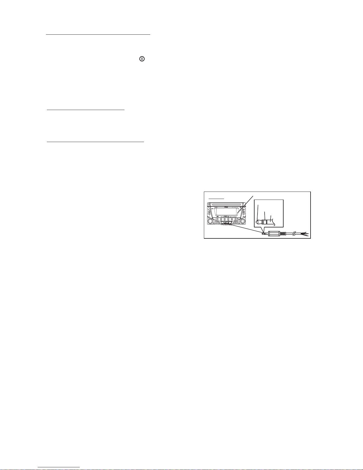
AUX INPUT
Connect the external signal to AUX in jack located at the
front of the panel , then press Mode button to select Aux
mode. Press Mode Button again to cancel Aux Mode
AUX IN
FRONT CABINET
LEFT TRACK
RIGHT TRACK
GROUND
and return to previous mode.
AUX IN
6) ENCODER VOLUME BUTTON
To increase the volume, rotate the volume control clockwise.To decrease the volume, rotate
the volume control counter clockwise.When volume is adjusted, the volume level will be
shown on the display panel as a number ranging from 0 (lowest) to 46 (highest).
12
Page 14

8. MENU OPERATION
18) MENU FUNCTION LIST (MENU)
Press DISPLAY/ MENU for more than 3 seconds to access the menu. will
appear in the display momentarily. Navigate the menu by pressing DISPLAY/ MENU
momentarily to move forward to the next option. The menu can also be navigated by using the
Tuning Up or Tuning Down Button to move to the next or previous option. Once the desired
option appears in the display, adjust that option by rotating the volume control within 5
seconds. The following options are adjusted through this menu feature.
Pairing
This feature is used to pairing the unit's Bluetooth system to your mobile phone or other
Bluetooth device. Under the MENU “Pairing” mode then press Audio button to start activating
the Pairing.
Tips
Please refer to BLUETOOTH HAND FREE operation regarding the details operation of
“PAIRING”.
Re-connection/Dis-connection
This feature is allows to Re-connect or Dis-connect to the paired mobile phone or Bluetooth
device by manually. Under the Menu- “RE-CONN”mode, Rotate the encoder to navigate thru
“RE-CONN” (re-connection) and “DIS-CONN”(Dis-connection). After selected the mode for
connection then press Audio button to start activating the connection mode.
Auto Answer (A ANSWER)
The unit is default of “off' mode. If “On” is selected.. The unit is automatically answer any
incoming call without pressing PHONE button if ON is selected..
Contrast
The contrast level of the display is set at "CONTRAST 05" by default. Rotate the volume control
To adjust the contrast level from 00 to 10.
Clock Format
This option allows selection of a 12 hour or 24 hour clock format. "CLK FORMAT 12H" is the
Default setting. Rotate the volume control to change to the 24 hour clock format.
Time Set
The time on the clock will be set to 12:00 as the default. Program the current time by rotating
the volume control clockwise to adjust the minutes and counterclockwise to adjust the hours.
Local / Distance Select
This feature is used to designate the strength of the signals at which the radio will stop during
automatic tuning. "Distance" is the default, allowing the radio to stop at a broader range of
signals. To set the unit to select only strong local stations during automatic tuning, rotate the
volume control until "Local" appears in the display.
Beep Tone
The beep tone feature allows the selection of an audible beep tone to be heard each time a
button is pressed on the face of the radio. "BEEP TONE On" is the default display. Rotate the
volume control to select the "BEEP TONE Off" option.
13
Page 15

9. AUDIO OPERATION
Audio Menu
Pressing “AUDIO button to access the Audio Menu. User can navigate thru the Audio Menu items
by pressing the / “AUDIO” button repeatedly, or by pressing the Tuning Up or Tuning Down Button.
Once the desired menu item appears on the display, adjust that option by using the Volume Up or
Down button within 5 seconds. The following menu items can be adjusted as described above.
The unit will automatically exit the Audio Menu after five seconds of inactivity.
VOLUME (Volume Level)
User has 5 seconds to use the Volume button to adjust the desire volume level, the volume
level will be shown on the LCD display ranging from 00 (lowest) to 46 (highest).
BASS (Bass Level)
User has 5 seconds to use the Volume Up or Down button to adjust the desired Bass level
range from -6 to +6.
TREBLE (Treble Level)
User has 5 seconds to use the Volume Up or Down button to adjust the desired Treble level
range from -6 to +6.
BALANCE
User has 5 seconds to use the Volume Up or Down button to adjust the Balance between the
right and left speakers from R12 (full right) to L12 (full left). “C00” represents an equal balance
between the right and left speakers.
”
FADER
User has 5 seconds to use Volume Up or Down button to adjust the Fader between the front
and rear speakers from R12 (full rear) to F12 (full front). “C00” represents an equal balance
between the front and rear speakers.
14
Page 16

10. TUNER OPERATION
7) BAND BUTTON (BAND/SEARCH)
Press BAND to change between FM bands and AM(MW) bands.
20) TUNING UP/DOWN BUTTON
Manual Tuning
Turn & Hold the Up Tuning or Down Tuning button for more than 3 seconds to move the
radio frequency number up or down one step.
Auto Seek Tuning
Turn & Hold the Up Tuning or Down Tuning button for less than 3 seconds to move to next
station automatically.
12-17) PRESET STATIONS BUTTONS
Six numbered preset buttons store and recall stations for each band.
Store a Station
Select a band (if needed), then select a station. Hold a preset button for 3 seconds. The
preset number will appear in the display.
Recall a Station
Select a band (if needed). Press a preset button to select the corresponding stored station.
11) AUTOMATICALLY STORE / PRESET SCAN (AS/PS)
Automatically Store
Automatically select 6 strong stations and store them in the current band. Select a band (if
needed). Press AS/PS button for more than three seconds. The new stations replace
stations already stored in that band.
Preset Scan
Scan stations stored in the current band. Select a band (if needed). Press AS/PS button for
less than 3 seconds. The unit will pause for ten seconds at each preset station. Press AS/PS
button again to stop scanning when the desired station is reached.
STEREO
The unit will automatically pick up a stereo signal, when available. When in stereo mode,
the ST icon appears in the display. When no stereo signal is available, the unit will
automatically revert to mono operation, and no icon will be displayed.
IMPORTANT NOTE ON THE EUROPEAN / RDS TUNER SETTING
This unit is default at "U.S.A" frequency. When unit is in U.S.A frequency, all the RDS related
function is disabled. Once user change the AREA setting to "EUROPE", unit will change to
European frequency, and all the RDS function will be activated as well. So all the RDS
related function will only be activated, only if this unit's AREA setting is change to EUROPE".
1) For details operation of the Menu-Tuner Setting, please refer to pag “ Menu Operation”.
2) For details operation of the RDS system, please refer to page “ RDS Operation”.
15
Page 17
11. RDS OPERATION
RDS functions
The unit is equipped with the following RDS function:
- AF Alternative Frequencies
- CT Clock Time
- EON Enchanced other Network
- PI Program identifications
- PS Program service name
- PTY Program Type
- REG Regional Change
- TA Traffic Announcement
- TP Traffic program
1. AF Function
By pressing AF button < 3 seconds to select AF ON/OFF. “AF ON” or “AF OFF” will show &
remain on the LCD segment for 5 seconds.. Under AF “On” mode, if the tuned in station signal is
getting weak, the unit will automatically switches to a different frequency on the same network
with stronger signal.
Note: Factory Default setting is “AF ON”
2. TA Function
By pressing TA button < 3 seconds, turn switch on TA standby mode. “TA ON” will show &
remain on the LCD segment for 5 seconds & the TA icon will light up on the LCD. In the stand by
mode, when a traffic announcement broadcast starts, the traffic announcement broadcast will
be received as top priority regardless of the function mode. When a traffic announcement
starts, “TRAFFIC INFO” will show on the LCD, press the TA button can cancelled the broadcast
reception while a traffic announcement broadcast is being received. The unit will go back to the
previous mode and TA goes into stand by mode again. When the TP icon is not light up for 60
seconds. A beep Alarm tone is heard and the LCD will show “Lost TP, TA”. TA seek will
automatic activate and searches to another TA station.
3. PTY Function
Pressing PTY button < 3 seconds to goes into PTY select mode. “PTY” icon will light up on the
LCD. The LED around encoder volume will starts blinking. The user now has 5 seconds to
select the desired PTY item by using volume up/down button. Once selected the PTY item, user
have 5 seconds to press “SELECT” or “TUNE UP or TUNE DOWN” buttons < 3 seconds to seek
for the selected PTY item. The LCD will display “PTY SEEK”. If no station with the selected PTY
broadcast can be received, the LCD will display “No Match PTY” and blinks for 5 seconds then
returns to the previous mode.
User can store his favor PTY into the preset memory M1 to M6. After selected a PTY item, long
press any one of the preset memory button can store the selected PTY. To recall the stored PTY
item by switching on PTY mode then press preset memory < 3 seconds, the unit will
automatically search the stored PTY station in the preset memory
Music Group
POP , ROCK
EASY, LIGHT
CLASSICS, OTHER
JAZZ, COUNTRY
NATION, OLDIES
FOLK
Note: Factory default stored for PTY preset memory.
M1/News, M2/Information, M3/Pop Music, M4/Sports, M5/Classics, M6/Finance.
Speech Group
NEWS, AFFAIRS, INFO
SPORT, EDUCATE, DRAMA
CULTURE, SCIENCE, VARIED
WEATHER,FINANCE, CHILDREN
SOCIAL, RELIGION, PHONE IN
TRAVEL, LEISURE, DOCUMENT
16
Page 18

12. CD /MP3/WMA OPERATION
INSERT AND EJECT CD
Insert a CD label-side up with the unit turned on, and the disc will begin to play. Press the Eject
button to stop CD play and eject the CD. The unit does not have to be turned on to eject the CD.
CD-DA OPERATION
12) PAUSE BUTTON
Press the pause button to suspend disc play. Press the pause button again to resume disc Play.
20) TRACK SELECT
Press the Up Tuning or Down Tuning button for less than one second to advance to the next
track on the CD, The selected track number will appear on the display. Press and hold the Up
Tuning or Down Tuning button for more than one second to fast forward or fast reverse through
the disc. CD play starts when the button is released.
14) REPEAT BUTTON (RPT)
Press REPEAT BUTTON (RPT) during disc play to continuously repeat the track. Press
REPEAT BUTTON (RPT) again to stop Repeating.
15) RANDOM BUTTON (RDM)
Press RANDOM BUTTON (RDM) during disc play to play all tracks on a CD in random, shuffled
order. Press RANDOM BUTTON (RDM) again to stop random play.
13) INTRO SCAN BUTTON (INT)
During disc play, press INTRO SCAN BUTTON (INT) to play the first 10 seconds to each track
on the disc. When the desired track is reached, press INTRO SCAN BUTTON (INT) again to
end the scan and play the selected track.
MP3/WMA OPERATION
MP3 and WMA (Windows Media Audio) music files are audio compression format. This unit can
play MP3/WMA directly from files contained on a CD-R/RW, USB Memory Stick, SD or MMC
Memory Card.
Notes on MP3/WMA Play
This unit can play MP3 (MPEG1, 2, 2.5 Audio Layer 3). However, the MP3 recording media and
accepted formats are limited. When writing MP3/WMA, pay attention to the following restrictions.
Acceptable Medium Formats
The following formats are available for the media used in this unit. The maximum number of
characters used for file name including the delimiter (".") and three-character extension are
indicated in parentheses.
ISO 9660 Level 1 (11 characters)
ISO 9660 Level 2 (31 characters)
Joliet (31 characters)
Romeo (31 characters)
Up to 200 characters can be displayed in the long file name format. For a list of available
characters, see the instruction manual of the writing software and the section “Entering File and
Folder Names” below. The media reproducible on this unit has the following limitations:
Maximum number of nested folders: 8
Maximum number of files per disc: 999
Maximum number of files per media device: 2000
Maximum number of folders per disc: 255
MP3/WMA written in the formats other than the above may not be successfully played and their file
names or folder names may not be properly displayed.
17
Page 19

MP3/WMA Encoder and CD Writer Settings
Use the following settings when compressing audio data in MP3 data with the MP3 encoder.
Transfer bit rate : 32- 320 kbps
Sampling frequency : 32,44.1,48 kHz(WMA) 16,22.05,24,32,44.1, 48kHz (MP3)
When using a CD writer to record MP3/WMA up to the maximum disc capacity, disable additional
writing. For recording on an empty disc up to the maximum capacity at once, check disc at once.
Entering ID3 Tag
This unit supports ID3 tag versions 1.0 and 1.1.
Entering File and Folder Names
Names using the code list characters are the only file names and folder names that can be entered
and displayed. Using any other character will cause the file and folder names to be displayed
incorrectly. The unit recognizes and plays only files with the MP3/WMA extension.
A file name entered with characters not on the code list may not play correctly.
Writing Files into a Media
When a media containing MP3/WMA data is loaded, the unit checks all data. If the media contains
many folders or non-MP3/WMA files, MP3/WMA play will be delayed, it may take time for the unit to
move to the next file, and searches may not be performed smoothly. Loading such a media may
produce loud noise and cause damage to the speakers. Do not attempt to play a media
containing a non-MP3/WMA file with the MP3/WMA extension or a media containing non
MP3/WMA files.
Bit Rates
The unit supports bit rates from 32 - 320 kbps.
Files Playing Order
When selected for play, Folder Search, File Search or Folder Select, files and folders are accessed
in the order in which they were written by the PC writer. Because of this, the order in which they are
expected to be played may not match the order in which they are actually played. For example, a
media with the following folder/file hierarchy is subject to Folder Search, File Search or Folder
Select as shown below.
An outline of a Media with MP3/WMA is shown below. Subfolders are shown as folders in the
folder currently selected.
1 LEVEL 2 LEVEL 3 LEVEL 4 LEVEL
ROOT
01
001.MP3
002.MP3
003.MP3
004.MP3
04
05
06
07
“NOT DISPLAY”
X
009.MP3
010.MP3
011.MP3
012.WMA
013.WMA
014.WMA
015.MP3
016.MP3
017.MP3
018.MP3
08
“NOT DISPLAY”
X
019.MP3
020.MP3
09
021.WMA
022.WMA
023.WMA
The equipment assigns folder
numbers. The user can not assign
folder numbers.
It is not possible to check folders that
do not include MP3/WMA files.
(These folders will be skipped without
displaying the folder number and
name)
“NOT DISPLAY”
X
02
03
“NOT DISPLAY”
005.MP3
006.MP3
007.MP3
008.MP3
X
18
Page 20
FILE/FOLDER PLAY
There are three different play methods as following:
File/Folder Intro play:
Press M2 button more than 3 seconds during playing MP3/WMA disc for “intro play” all files of
the current folder. Intro play should restart from the first song of the current folder, after all files in
the current files have been intro-played.
To disable current folder “intro play”, long press M2 button more than 3 seconds
Press M2 button less than 3 seconds is “intro play” all files on the disc. Intro play should re-start
at the very first file of the disc after all files in the disc has been intro played.
To disable all files “intro play”, press M2 button less than 3 seconds
File/Folder Repeat play :
Press M3 button more than 3 seconds during playing MP3/WMA disc for “repeat play” all files of
the current folder. And keep on repeat playing the current folder until “repeat play” is disabled.
To disable current folder “repeat play”, long press M3 button more than 3 seconds
Press M3 button less than 3 seconds to “repeat play” the current file. And keep on repeat
Playing the current file until the “repeat play” is disabled.
To disable current file “repeat play”, press M3 button less than 3 seconds
File/Folder Random play:
Press M4 button more than 3 seconds during playing MP3/WMA disc to “random play” all files
of the current folder.
To disable current folder “random play”, long press M4 button more than 3 seconds
Press M4 button less than 3 seconds is “random play” all files on the disc.
To disable all file “ random play”, press M4 button less than 3 seconds.
Folder Up / Down Play
Press M5 button less than 3 seconds to One Folder Down
Press M6 button less than 3 seconds to One Folder Up
MP3/WMA File or Folder Search
Direct File Number Searching
Press BAND button. The LCD will display "Number", and the illumination around the select knob
will blink. Rotate the knob to select the desired track number, then press in on the knob to confirm
and play the selected file.
Folder / Files Navigate Searching
Press BAND button twice. The LCD will display "Navigate", and the illumination around the select
knob will blink. Rotate the knob to navigate through all folders and sub-folders on the disc. The
folder names will be displayed on the LCD. Press the select knob for more than three seconds to
play the first file in the folder. Press the select knob for less than three seconds to access the subfolders or files. Rotate the select knob to navigate, then press the select knob to confirm and begin
file play. During navigation search, press AS/PS or rotate the select knob counter-clockwise to
move back to the last upper level of a folder.
ID3 INFORMATION DISPLAY
If any MP3/WMA file recording with ID3 Tag information. The ID3 information such like Album title,
Track title, Artist Title will be displayed and automatic scrolling through the LCD while the file is playing.
User also allows pressing the AS/PS button repeatedly to view the ID3 tag information manually.
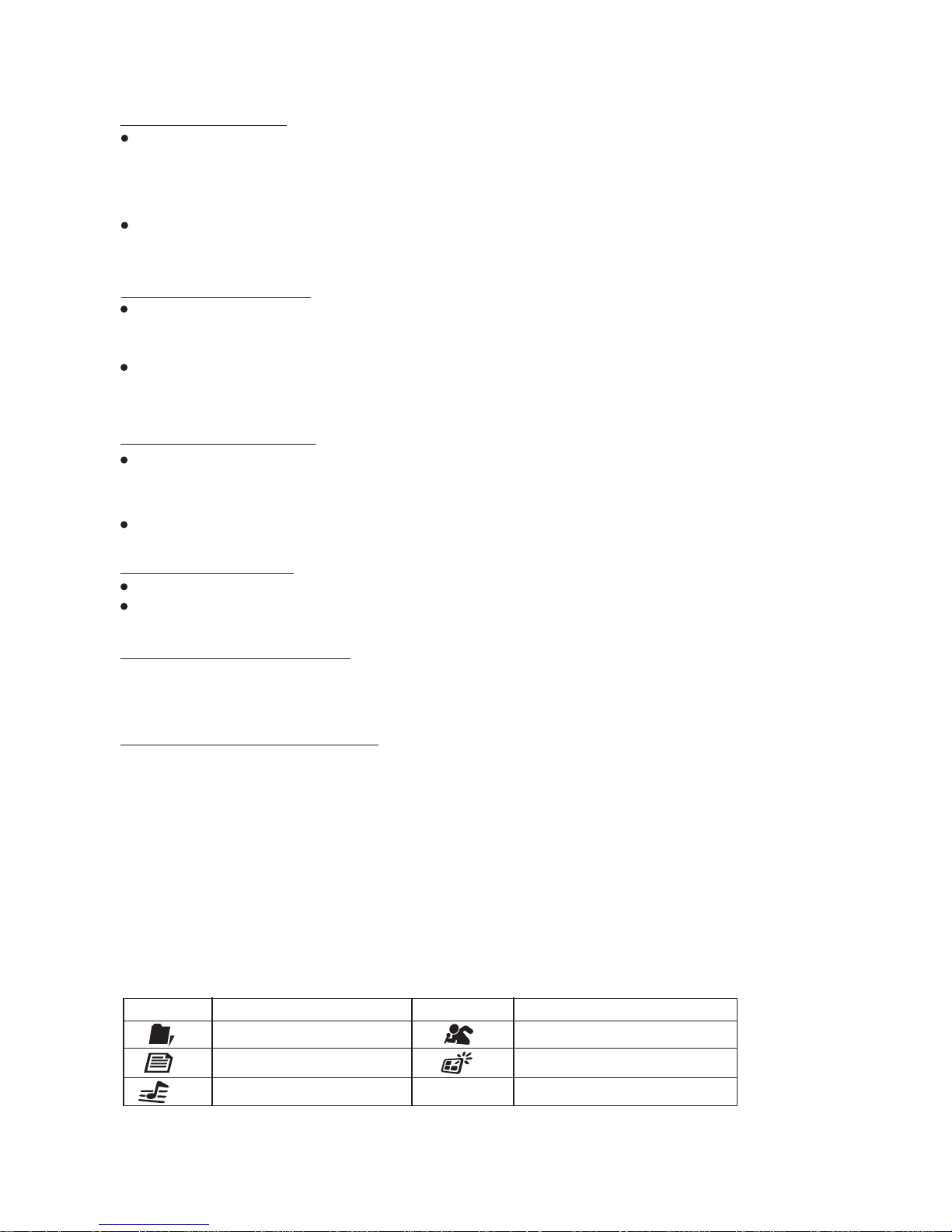
NOTE OF ID3 ICONS ON DISPLAY
ICON DESCRIPTION
FOLDER ICON
FILE ICON
TRACK ICON
ICON DESCRIPTION
ARTIST ICON
ALBUM ICON
19
Page 21
13. USB OPERATION
The unit can support USB Host Function. It can playback MP3 and WMA Audio format which are
stored into USB Memory Stick or USB interface Music Player. Please read below before you start
the operation of USB HOST Function.
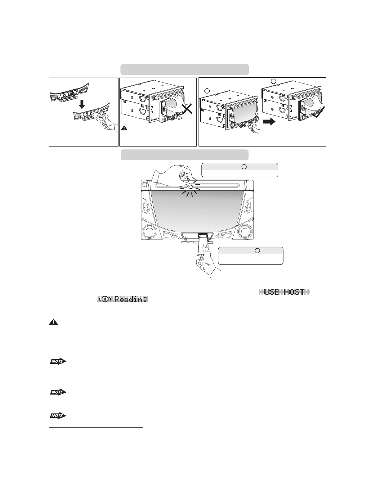
Inserting and Removing USB Drive
2
1
Warning:
Inserting the USB stick
Never Detach the Panel when a
USB stick was plug on the socket
Removing USB Drive
Always remove the USB stick before detach
Step
Secure panel with left hand
the panel
1
2
Step
Carefully remove USB drive
Mode change to USB HOST
Under any other mode while inserting a USB Stick into the front panel USB plug, the unit will automatically
switches from present playing mode to USB Host mode. The unit will display ‘ for a
.
while then starts the files contained on the USB Stick. Once the unit read the USB
Stick successfully, the first audio music file on the USB stick Playback will automatically start. Press Mode
button repeatedly to change other modes or switch back to USB HOST.
WARNING:
Before remove the USB stick from the Front panel USB plug. Always remember to switch off the
unit's power or switch to other mode then remove out the USB Stick. Never try removing the USB
Stick while playing music file on the USB stick. It may damage the USB Stick and sometimes will
caused the unit system lock up.
The unit can support playback Music Player which have USB Interface. However due to
the fast changing decoder technology and different kind of hardware interface. This unit
may or may not be compatible to all the Music Player and USB Stick especially those USB
Stick / Player which require to install a program driver.
About Music Flash Player with USB Interface, Usually, the unit takes longer time to read
this kind of player than normal USB Stick. Especially, if the Flash Player with built-in power
battery sometimes takes 20-30 seconds to start up the playback
The unit is not compatible to playing any Portable Hard disk.
Music File Playback Operation
All the USB playback operation function is same as the operation on MP3/WMA. Please refer to
'MP3/WMA Operation' for more details.
20
Page 22

14. MEMORY CARD OPERATION
The unit can support playback MP3 and WMA Audio format which are stored into SD and MMC
Memory Card . Please read below before you start the operation of Memory Card.
Inserting and Removing a SD or MMC card on the main unit
Inserting the SD or MMC card
1
Detach the Front Panel
1
2
Face
Up
Insert the Memory Card
with Label up side
Removing the SD or MMC card
2
Click
3
Click
Push in till heard a “click”
3
Detach the Front Panel Push in till heard a “click” Remove the Memory Card
Mode change to MEMORY CARD
After a SD or MMC card was inserted into the main unit card slot. Press the Mode button to select
mode . The unit will display for a while then starts
The files contained on the Memory Card. Once the unit read the MEMORY
.
CARD successfully, the first audio music file on the Memory Card will automatically start
playback.Press Mode button repeatedly is allowing changing to other modes or switch back to
.
mode.
If no any Memory Card is inserted into the main unit card slot. Press mode button will
automatically skip mode.
Music File Playback Operation
All the SD or MMC Memory Card playback operation function is same as the operation on
MP3/WMA. Please refer to 'MP3/WMA Operation' for more details.
21
Page 23

15. MUSIC FILES COPYING / TRANSFERRING
Thanks for the most useful and convenient files transferring function of this unit, user can easily
transfer music files between USB Stick, SD or MMC Memory card or Built-In Memory and on the
CD Disc. Please read below for the details operation of this function:
TRANSFERABLE MEDIA
Files are transferable within the following media:
Removable USB Stick
SD Memory Card
MMC Memory Card
File on the CD disc
Built-In Memory
MUSIC FORMAT SUPPORTED BY FILE TRANSFER ARE
MP3 and WMA
TRANSFER MP3 OR WMA MUSIC FILES ON CD DISC
This operation only can be performed during disc playing a MP3 or WMA music file.
1. Playback a music file to be transferred and then long press the COPY button to activate the
Transfer mode.
2. The LCD will display as default, Rotate the encoder volume knob to navigate
thru for selection of the storage media.
3. Once selected the storage media, Press AUDIO button as confirmation to transfer the playing
file. If no further button is press within a 10 second time out, the unit will automatically resume to the
previous mode.
4. If unit detect the selected media memory capacity is used up, will be
displayed on the LCD for a while then automatically resume to previous mode.
5. After pressing AUDIO button to start the transfer, the playing music file will stop and
thetransferring will start at the same time. (The following step is an example of if selected USB)
6. When the transfer is processing, the LCD will displayed .
7. When the file transfer is completed, the LCD will display for a while and
automatically playback the present music file which have been transferred. The transferred music
file is automatically saved as a file into Folder “MY_MP3” or “ MY_WMA” by the advance “File
Management.” system of this unit.
For more details information of File Management system of this unit. Please see “FILE
Tips
MANAGER’’.
Under transferring mode, All the MP3/WMA operation is not functional, like file up /
down,Repeat, Random, and Intro etc.
The audio will remain recording by the unit system even MUTE function is activated
The Transferring will automatically stop if the storage device memory is less than 2MB
To Cancel Transferring.
1. Long press button COPY again to cancel the recording. The LCD will display
the music file that has been transferred incompletely will be deleted.
The unit will stop the file transfer automatically under the following operation, the music
file that has been transferred incompletely will be deleted.
1) Switch the power to off mode
2) Mode change
3) Inserting a CD Disc
4) Inserting a USB Stick
22
Page 24

TRANSFER MP3 OR WMA MUSIC FILES BETWEEN MEDIA DEVICES
Select a device by mode button and playback the music file need to be transfer:
1. Long press the COPY button to activate the transfer mode.
2. The LCD will display as default, Rotate the encoder volume knob to navigate
thru for selection of the storage media.
3. Once selected the storage media, Press AUDIO button as confirmation to transfer the playing
file. If no further button is press within a 10 second time out, the unit will automatically resume to the
previous mode.
4. If unit detect the selected media memory capacity is used up, will be
displayed on the LCD for a while then automatically resume to previous mode.
5. After pressing AUDIO button to start the transfer, the playing music file will stop and
thetransferring will start at the same time. (The following step is an example of if selected USB)
6. Under the transfer is processing, the LCD will displayed .
7. When the file transfer is completed, the LCD will display for a while and
automatically playback the present music file which have been transferred. The transferred music
file is automatically saved as a file into Folder “MY_MP3” or “ MY_WMA” by the advance “File
Management.” system of this unit.
For more details information of File Management system of this unit. Please see “FILE
Tips
MANAGER’’.
Under transferring mode, All the MP3/WMA operation is not functional, like file up /
down,Repeat, Random, and Intro etc.
The audio will remain recording by the unit system even MUTE function is activated
The Transferring will automatically stop if the storage device memory is less than 2MB
WARNING:
1) Never remove the USB Stick while recording or file transferring to USB Stick. It may damage the
USB Stick and sometimes will caused the unit system lock up.
2) It is not recommended to insert USB stick while recording is under progress to other
storage device. Always remember to stop the recording or after the recording is completed,
then insert the USB stick.
3) Do not switching mode of the unit during the File Transferring .
4) Do not turn off the Power of the unit during the File Transferring.
5) Do not switch the ignition key off during the File Transferring
23
Page 25
16. MUSIC FILES ERASING
You can erase files from the USB Stick or Memory Card. Please read below for the details
operation of this function:
ERASABLE MEDIA
USB Stick and Memory Card .
ERASING MUSIC FILES ON THE MEDIA
There are THREE different methods for erasing files;
1.Erase while the Music File is playing.
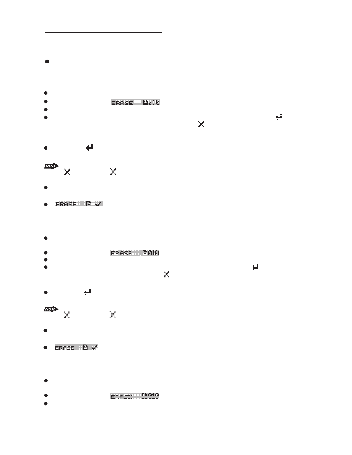
Long press BAND button to activate the ERASE mode
The LCD will display
Short Press the AUDIO to enter into the ERASE mode.
Once enter into the erase mode. You can rotate the encoder volume knob to select “ ” as to
confirm the erase or rotate the volume knob to select “ ” as for cancel the erase mode. If no
further button is press within 5 seconds time out. The unit automatically resume to the previous
mode.
Once the “ ” is display on the LCD, press the AUDIO button again to final confirm
the present playback music file.
If want to CANCEL the erase of the present music file, Rotate the encoder volume knob to “
”. Once the “ ” is displayed on the LCD, press the AUDIO button again to cancel the
erase mode.
After pressing AUDIO button to start the ERASE, the present playing music file will stop and
the erasing will start at the same time.
Will display on the LCD after the music file erase is successful, and the unit
will automatically start playback the next music file.
erase
2.Erase under Files Number Search Mode
User can select the Music file Number want to erase by file Number Search mode.
After selected the file number want to erase, Long press the BAND button to activate the
ERASE mode.
The LCD will display .
Short Press the AUDIO to enter into the ERASE mode
Once enter into the erase mode. User can rotate the encoder to select “ ” to confirm
erase or rotate the volume knob to select “ ” to cancel the ERASE mode. If no further button is
press within a 5 second time out. The unit automatically resume to the previous mode.
Once the “ ” is displayed on the LCD, press the AUDIO button to final confirm to erase
selected music file.
If want to CANCEL the erase of the present music file, Rotate the encoder volume knob to “
”. Once the “ ” is displayed on the LCD, press the AUDIO button again to cancel the
erase mode.
After pressing AUDIO button to start the ERASE, the present playing music file will stop and
the erasing will start at the same time.
Will display on the LCD after the music file erase is successful, and the unit
will automatically start playback the next music file.
3. Erase under Files NAVIGATE search mode
You can select a Music file want to erase by files Navigate Search mode.
After selected the file number want to erase, Long press the BAND button to activate the
ERASE mode.
The LCD will display .
Short Press the AUDIO to enter into the ERASE mode.
the
the
24
Page 26

Once enter into the erase mode. User can rotate the encoder to select “ ” to confirm
erase or rotate the volume knob to select “ ” to cancel the ERASE mode. If no further button is
press within a 5 second time out. The unit automatically resume to the previous mode.
the
Once the “ ” is displayed on the LCD, press the AUDIO button to final confirm to erase
selected music file.
If want to CANCEL the erase of the present music file, Rotate the encoder volume knob to “
”. Once the “ ” is displayed on the LCD, press the AUDIO button again to cancel the
erase mode.
After pressing AUDIO button to start the ERASE, the present playing music file will stop and
the erasing will start at the same time.
Will display on the LCD after the music file erase is successful, and the unit
will automatically start playback the next music file.
WARNING:
1) Do not switching mode of the unit during the Erasing
2) Do not turn off the Power of the unit during the Erasing
3) Do not switch the Ignition key off during the Erasing
4) Do not detach the front panel during the Erasing
the
25
Page 27

17. FILES MANAGER
The advance “File Management.” System of this unit can help to well you organize all the music
files just like a PC . Please read below for details:
FOLDERS MANAGEMENT
This unit will automatically self-create the below default folders onto any USB /SD / MMC media
device, once these devices are inserted into the unit.
MY_CD: Folder for saving all the music files from CD Disc.
MY_MP3: Folder for saving all the MP3 music files transfer from other device
MY_WMA: Folder for saving all the WMA music files transfer from other device
MY_Aux: Folder for saving all the music files source from Aux In
FILES MANAGEMENT
This unit will automatically self-create the file name following with the Folder Name, for example:
Music file which recorded from file, the file name ‘ will be automatically created & saved in the
respective folder.
Mp3'
26
Page 28

18. BLUETOOTH HAND FREE OPERATION
User Guide For Bluetooth Operation
1. When user use our Bluetooth HEAD UNIT, please make sure the mobile phone you use must /
does support Bluetooth functions (Headset or Handsfree profiles or both)
2. Before you start to use our Bluetooth HEAD UNIT, please make sure complete pairing with your
mobile phone first. Please refer to the user manual, section “PAIRING” for detail “PAIRING”
instruction. To ensure the best reception for Pairing or Re-connection, please make sure the Phone
Battery is fully charged when making the Pairing or Re-connection.
3. Please always try pairing the Mobile Phone with Head unit after a few minutes of the Mobile
Phone was Switched On to ensure the best pairing result.
4. “BT60” is this unit device model number which is displayed on the mobile phone.
5. To achieve the best performance, please always keep the Mobile Phone within 3 meters of the
Head unit.
6. Please always keep a clear path between the Mobile Phone & the Head unit.
7. Never put any metal object or any obstacle between the path of the Mobile Phone & the Head
unit.
8. Some brand of Mobile Phone like Sony Ericsson may have "Power Saving Mode" selection when
Bluetooth mode is switched on. PLEASE DO NOT Switches ON Power saving Mode when
operating with this Head Unit, as some abnormal communal behavior will happen occasionally if
Power Saving Mode is switched on.
9. Before user make Outgoing call or Incoming call, make sure the mobile phone's “Bluetooth
function” was switched “ON”.
10. To ensure the best conversation quality / performance, please always keep talking within 1
meter of the Head Unit.
11. If user want to Dis-connect the Head unit with the Mobile Phone, please switch "OFF" Bluetooth
connectivity on the Mobile Phone,or go to the system menu, "dis-connect" to disconnect the
bluetooth connectivity manually. ( please refer to the user manual, section "dis-connection of the
bluetooth system for details instruction. )
12. Some Mobile Phones can support “IN BAND RING TONE”, such as Nokia. In such case, the
Incoming Ringing Tone will be same as the original Ring-tone of the Mobile Phone. But some
Mobile Phones like Sony Ericsson do not support this feature. The Ring-tone will be using the
standard Ring-tone of the Head unit.
13. When in telephone mode, during talking, it is highly recommended to set the volume to below
“30” in order to achieve the best sound quality. As if the volume is too high, it may create unwanted
echo inside the car, and this unwanted echo may feedback into the microphone.
14. If the Bluetooth related operation is not performing normally, like cannot make pairing, cannot making
an outgoing call, User can try to make a SOFT-RESET of the Bluetooth module by removing / detaching
the panel from the main unit and waiting for about 1 min. Then re-attach the panel to the unit & retry the
Bluetooth operation again. Or user can RESET the whole unit by pressing the RESET button behind the
panel.
By pressing the RESET button all the stored memory will resume to factory default
27
Page 29
Bluetooth Mobile Phone Compatibility List
This unit can support Bluetooth specification v1.2 or higher, and compatible with Bluetooth profiles
such as handsfree or headset profiles. however the functionality may be limited due to some
phones' own dedicated interfacing specification.
This list is only updated to the time this list is being printed. This list gives an example of bluetooth
mobile phone available on the market, if your Bluetooth mobile phone is not on the list, please try it
out in practice or try your phone at the local dealer or consult with the local dealer in case it is not
mentioned in the list.
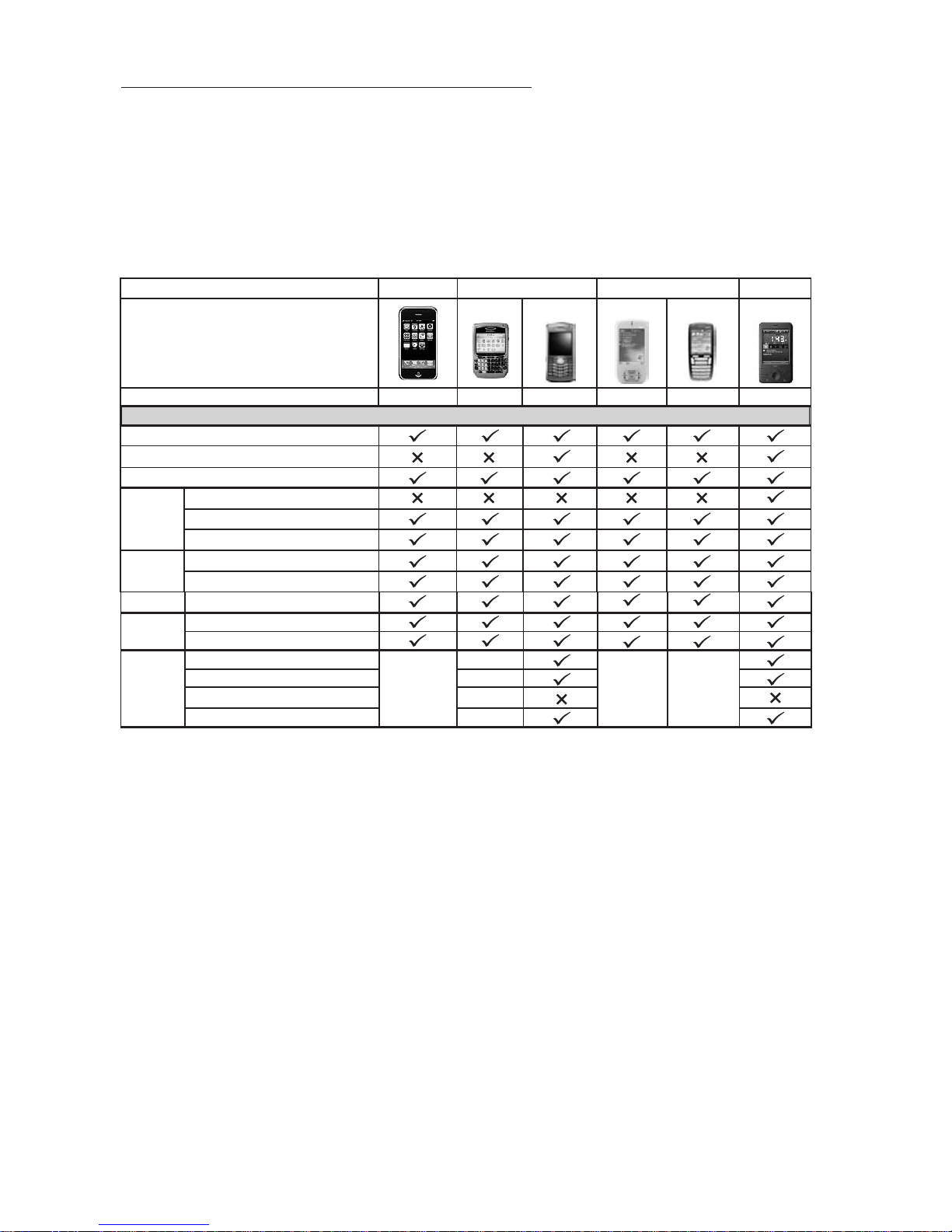
1. APPLE, BlackBerry, DOPOD & HTC
APPLE
BlackBerry
DOPOD
HTC
Features
Caller ID
A2DP/AVRCP
Paring
Ringing
Talking
Dialing
Stereo
Control
BlackBerry
Pearl 8120
818 565
Not Supported
this function
Not Supported
this function
P3470
i-phone
In-Band Ring Tone
Talk
Reject
Audio Transfer
Volume up/down
Hang up
Audio Transfer
Volume up/down
Stop/Pause/Play
Volume control
Forward/Backward
Next/Previous
Not Supported
this function
28
Page 30

2. HTC & LG
HTC
LG
Features
Caller ID
A2DP/AVRCP
Paring
Ringing
Talking
Dialing
Stereo
Control
HTC TyTNII HTC Touch
KS 20 LG Viewty KG320 Shine KE970
In-Band Ring Tone
Talk
Reject
Audio Transfer
Volume up/down
Hang up
Audio Transfer
Volume up/down
Stop/Pause/Play
Volume control
Forward/Backward
Next/Previous
Not Supported
this function
29
Page 31

3. MOTOROLA
Features
Caller ID
A2DP/AVRCP
Paring
Ringing
Talking
Dialing
Stereo
Control
Paring
In-Band Ring Tone
Talk
Reject
Audio Transfer
Volume up/down
Hang up
Audio Transfer
Volume up/down
Stop/Pause/Play
Volume control
Forward/Backward
Next/Previous
MOTOROLA
V9 E8
Q9h Z6 E6 V8
Features
Caller ID
A2DP/AVRCP
Paring
Ringing
Talking
Dialing
Stereo
Control
In-Band Ring Tone
Talk
Reject
Audio Transfer
Volume up/down
Hang up
Audio Transfer
Volume up/down
Stop/Pause/Play
Volume control
Forward/Backward
Next/Previous
K1
明 (A1200)
V3x V3 V600 V501
Not Supported
this function
Not Supported
this function
Not
Supported
this function
30
Page 32

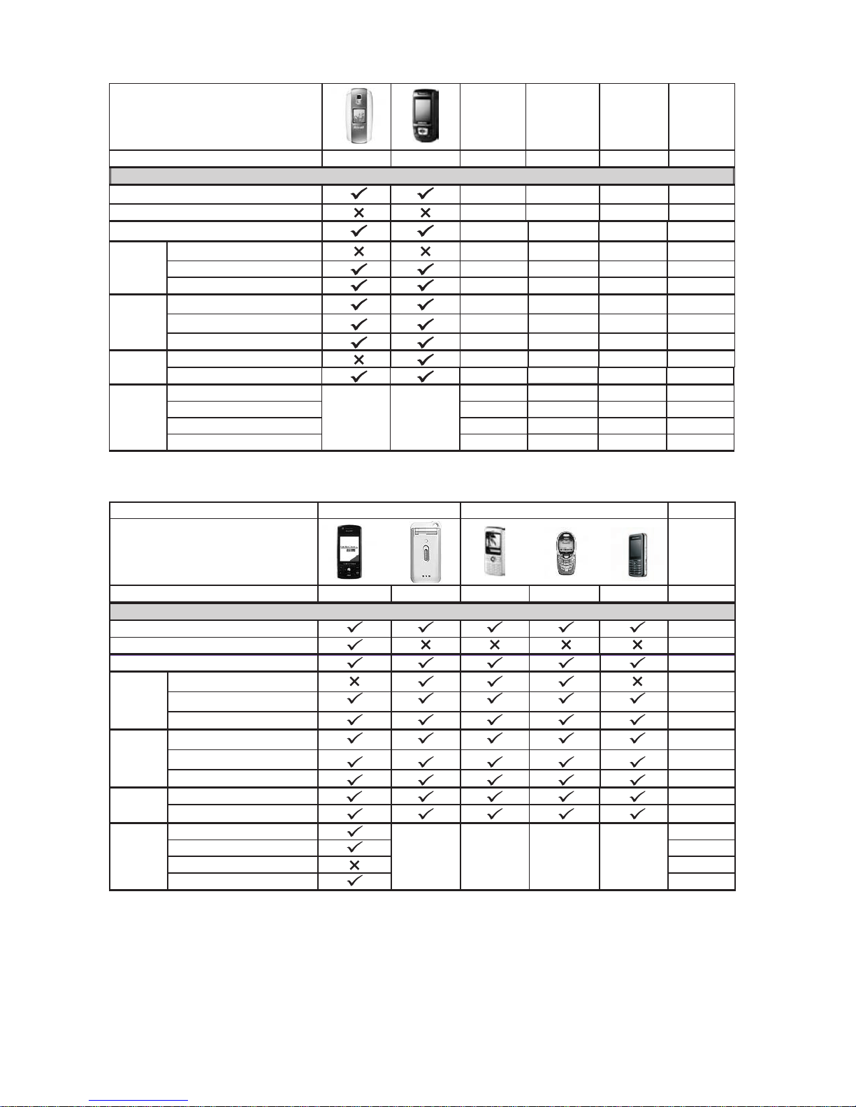
4. NOKIA
Features
Caller ID
A2DP/AVRCP
Paring
Ringing
Talking
Dialing
Stereo
Control
In-Band Ring Tone
Talk
Reject
Audio Transfer
Volume up/down
Hang up
Audio Transfer
Volume up/down
Stop/Pause/Play
Volume control
Forward/Backward
Next/Previous
N95 N81 5610 6110 6300 5700
NOKIA
Features
Caller ID
A2DP/AVRCP
Paring
Ringing
Talking
Dialing
Stereo
Control
In-Band Ring Tone
Talk
Reject
Audio Transfer
Volume up/down
Hang up
Audio Transfer
Volume up/down
Stop/Pause/Play
Volume control
Forward/Backward
Next/Previous
6233 5300 7500 6085 N91 N73
Not Supported
this function
Not
Supported
this function
31
Page 33

NOKIA
Features
Caller ID
A2DP/AVRCP
Paring
In-Band Ring Tone
Ringing
Talking
Dialing Audio Transfer
Stereo
Control
Talk
Reject
Audio Transfer
Volume up/down
Hang up
Volume up/down
Stop/Pause/Play
Volume control
Forward/Backward
Next/Previous
5. SAMSUNG
6111 6270 6600 6230
Not Supported
this function
Not Supported
this function
Not Supported
this function
Not Supported
this function
Features
Caller ID
A2DP/AVRCP
Paring
Ringing
Talking
Dialing
Stereo
Control
In-Band Ring Tone
Talk
Reject
Audio Transfer
Volume up/down
Hang up
Audio Transfer
Volume up/down
Stop/Pause/Play
Volume control
Forward/Backward
Next/Previous
I458 F338 U708 Z728 D820 D528
32
Page 34
SAMSUNG
Features
Caller ID
A2DP/AVRCP
Paring
In-Band Ring Tone
Ringing
Talking
Dialing Audio Transfer
Stereo
Control
Talk
Reject
Audio Transfer
Volume up/down
Hang up
Volume up/down
Stop/Pause/Play
Volume control
Forward/Backward
Next/Previous
6. SHARP & SIEMENS
E568 D508
Not Supported
this function
Not Supported
this function
SHARP
SIEMENS
Features
Caller ID
A2DP/AVRCP
Paring
Ringing
Talking
Dialing
Stereo
Control
WX-T82 WX-T71 GX-T15
In-Band Ring Tone
Talk
Reject
Audio Transfer
Volume up/down
Hang up
Audio Transfer
Volume up/down
Stop/Pause/Play
Volume control
Forward/Backward
Next/Previous
Not Supported
this function
Not Supported
this function
S55 BenQ S88
Not Supported Not Supported
this function
this function
33
Page 35
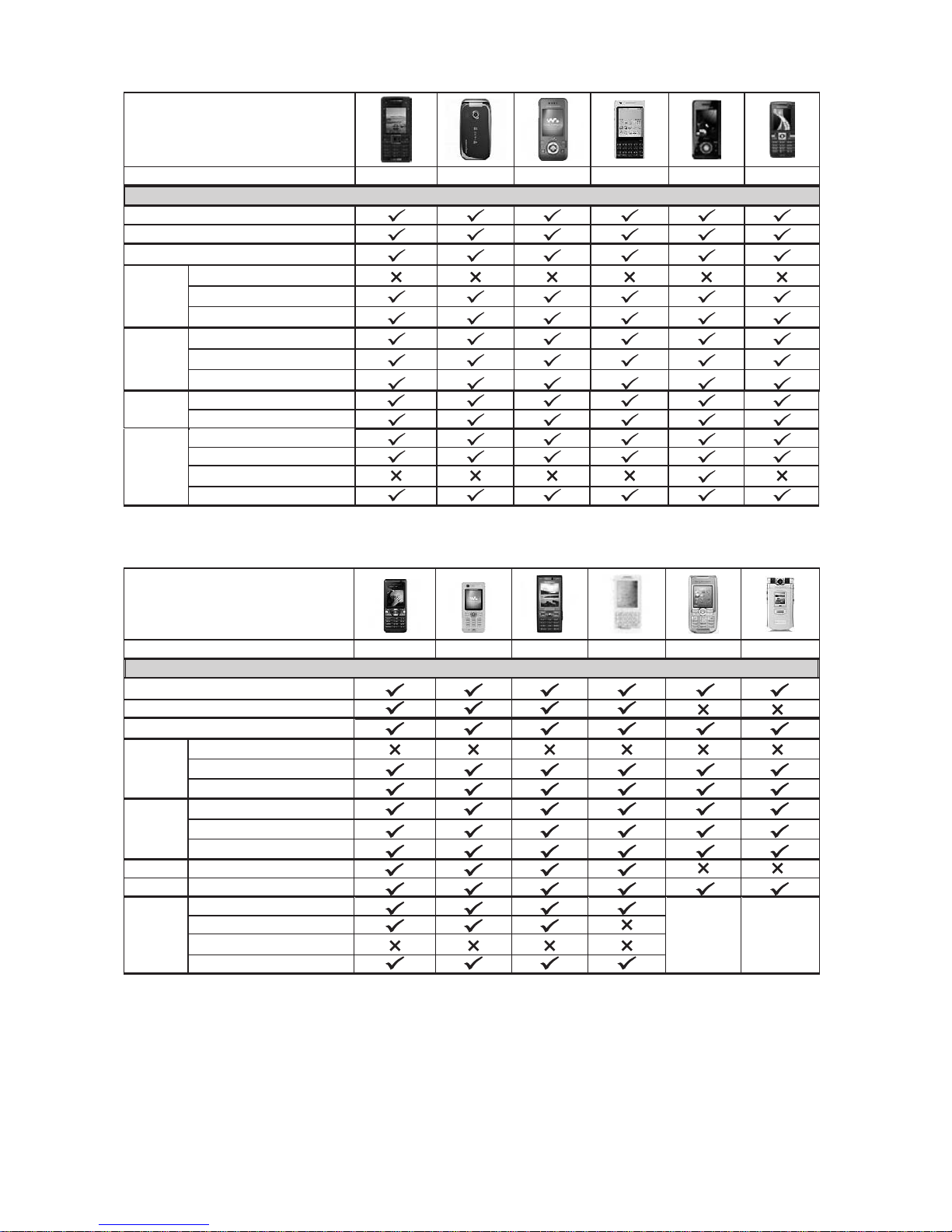
7. SONYERICSSON
Features
Caller ID
A2DP/AVRCP
Paring
In-Band Ring Tone
Ringing
Talking
Dialing
Stereo
Control
Talk
Reject
Audio Transfer
Volume up/down
Hang up
Audio Transfer
Volume up/down
Stop/Pause/Play
Volume control
Forward/Backward
Next/Previous
SONYERICSSON
C902 Z750i W580i P1i S500i K610i
Features
Caller ID
A2DP/AVRCP
Paring
In-Band Ring Tone
Talk Ringing
Reject
Audio Transfer
Volume up/down Talking
Hang up
Dialing Audio Transfer
Stereo
Control
Volume up/down
Stop/Pause/Play
Volume control
Forward/Backward
Next/Previous
K618i W880i K800i M600i K700i Z800i
Not Supported
this function
Not Supported
this function
34
Page 36
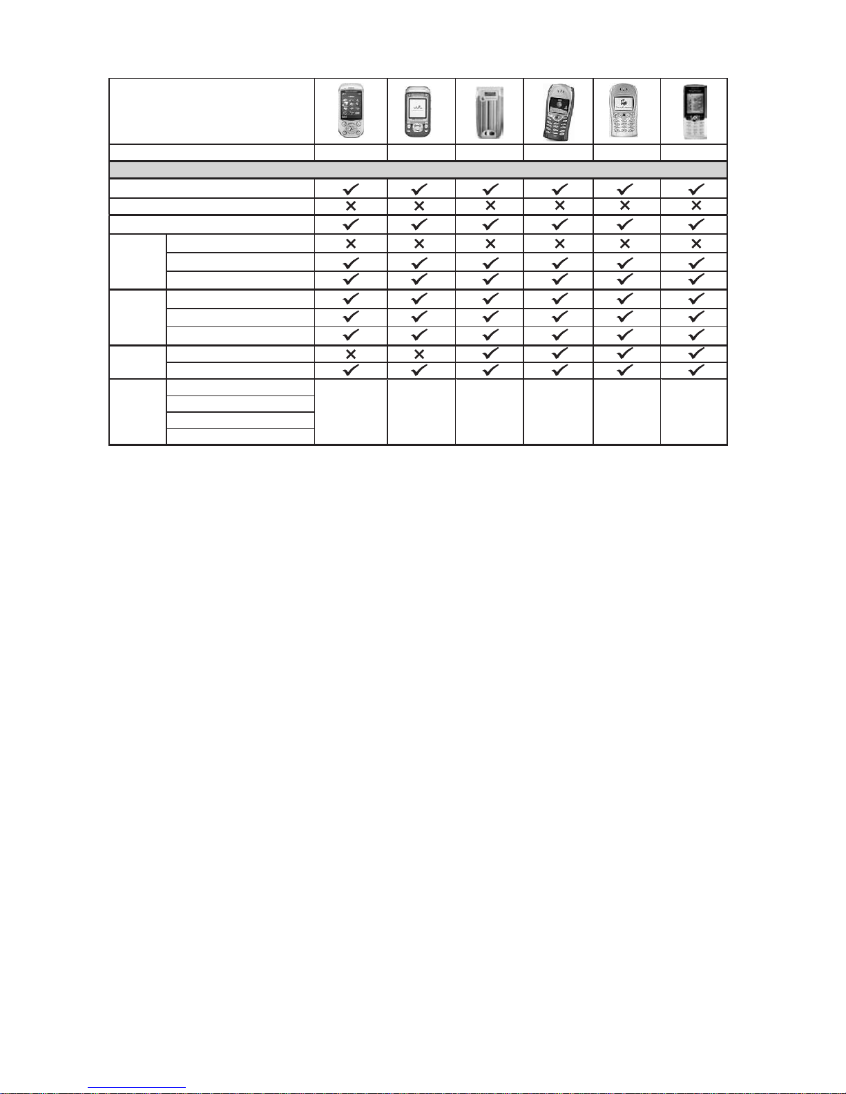
SONYERICSSON
Features
Caller ID
A2DP/AVRCP
Paring
In-Band Ring Tone
Ringing
Talking
Dialing Audio Transfer
Stereo
Control
Talk
Reject
Audio Transfer
Volume up/down
Hang up
Volume up/down
Stop/Pause/Play
Volume control
Forward/Backward
Next/Previous
S700i W550i Z600 T68 T68i T610
Not Supported
this function
Not Supported
this function
Not Supported
this function
Not Supported
this function
Not Supported
this function
Not Supported
this function
35
Page 37

BLUETOOTH HAND FREE PANEL FUNCTION KEY MATRIX
4
1
2
3
5
6
1
2
3
4
5
6
Panel Function Button
AUDIO
Encoder volume Knob
MODE
Tune Up / Down
Short Press
Long Press
BAND
Short Press
Long Press
MENU
Blue Tooth Hand Free Function
Enter Phone number input mode
Confirm Dialing the input Phone Number
Use for numeric input
1. Reject Incoming call
2. Edit Number
Confirm Dialing the input Phone Number
Transfer Phone Conversation backward to
Mobil Phone
Pairing / Re-Connection etc
Note: See Menu operation for more details.
Move Cursor and Edit Number
36
Page 38
PAIRING
Pairing The Bluetooth System Between User’s Mobile Phone & The Unit
Access into MENU - PAIRING mode to activates the operation of Pairing .
Please see MENU Operation for more details of how to access into MENU mode .
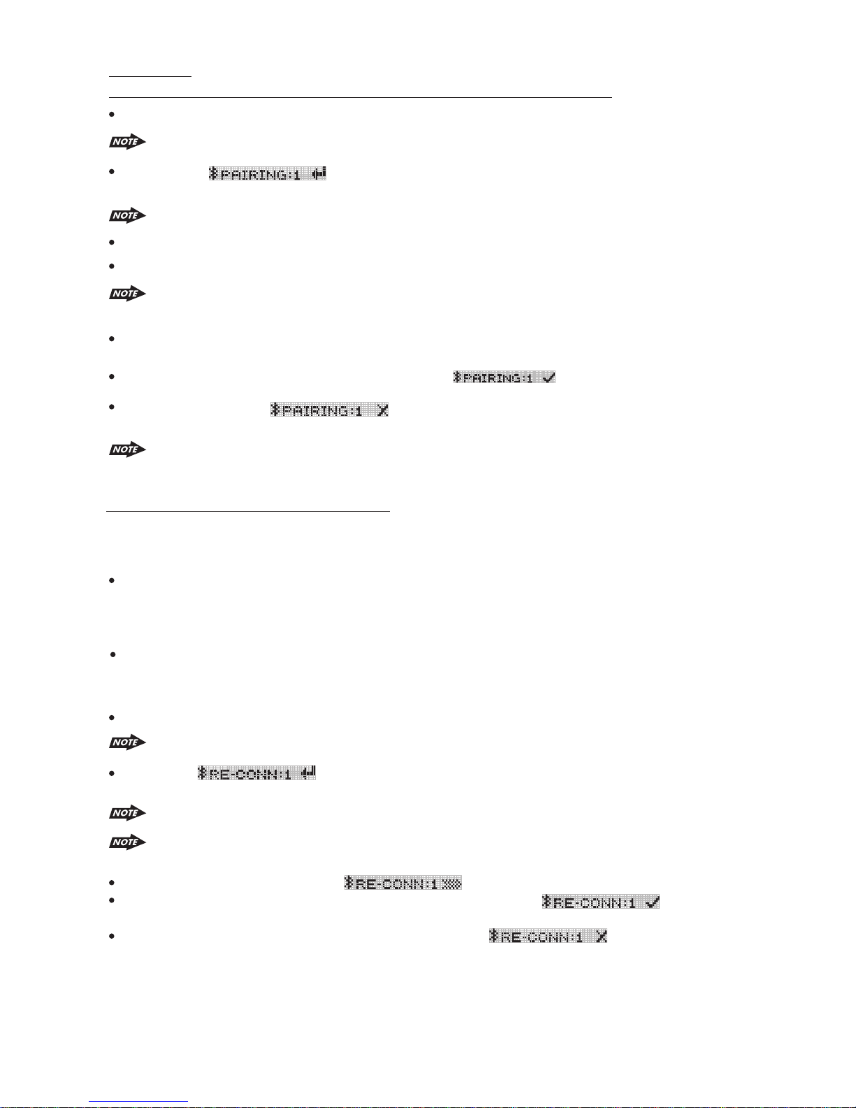
Once the is appearing on the LCD Display, press the AUDIO button to
activate the Pairing mode.
Keep the mobile phone within 2 meter from the unit when making the pairing.
To terminate the pairing, you can press the “CLEAR” button at any time.
Select the Bluetooth set up on the Mobile Phone.
Please refer to the instruction manual of your mobile phone on how to enter into the
Bluetooth set up and Bluetooth on / off, and Bluetooth pairing.
“BT60” “BT60”
and then input the password “1234”.
If the pairing is successful, the display will show nd Mobile Phone Name.
If the pairing failed, “ ” will be flashing on the Display for 3 seconds. And
the unit will switch back to the previous mode automatically.
Re-Connection Of The Bluetooth System
The unit is with built -in Auto-Reconnection function. In some conditions, user need to reconnect
manually. For example like the following.
If The Mobile Phone is out of range.( 2 meters away from the Head unit) Under the condition of
lost connection when the user come back to the unit. At the same time, there is an incoming
call or user is under conversation on the Mobile Phone 2 meters away from the Head Unit and
come back to Head unit.
If user wants Audio Transfer back from Mobile Phone to Head unit. It needs to re-connect
manually.
The unit can be re-connected by the following methods.
Access into MENU - RE-CONN mode to activate the manual RE-Connection.
should appear in the pairing list on the mobile phone. User need to select
During the Pairing, only Power, Clear ,Volume +/- & Mute are functional, other function
keys are disabled & non-operational during the pairing mode.
Please see MENU Operation for more details of how to access into MENU mode.
a
Once the is display on the LCD , press the AUDIO button to activate the
manual Re-Connect mode.
1.Keep the mobile phone within 2 Meter from the unit when making the connection.
2.The manual re-connect is only function with the Mobile Phone has already been paired
with the unit before.
The LCD Display will displayed “ ” during the connecting period.
If the re-connection is successful, the LCD Display will display “ ”. And the
unit will switch back to the previous mode automatically.
If the re-connection failed, the LCD Display will display “ ” . And the unit will
switch back to the previous mode automatically.
37
Page 39
The unit will be Auto Re-Connection by following operation .
Every time turn the ignition key from off to on, the unit will Auto re-connect with the mobile
phone one.
Every time when user long press AUDIO button or short press MODE button confirm dialing a
call, the Unit will Auto Re-connect with the Mobile Phone once ( Only if this Mobile Phone has
been paired with the unit previously ).
Dis-Connection of the Bluetooth System
The unit have a option function for user to disconnect the Bluetooth system with the unit. The unit
can be Dis-connected by the following methods.
Access into MENU - DIS-CONN mode to activate the manual Dis-Connection.
Please see MENU Operation for more details of how to access into MENU mode.
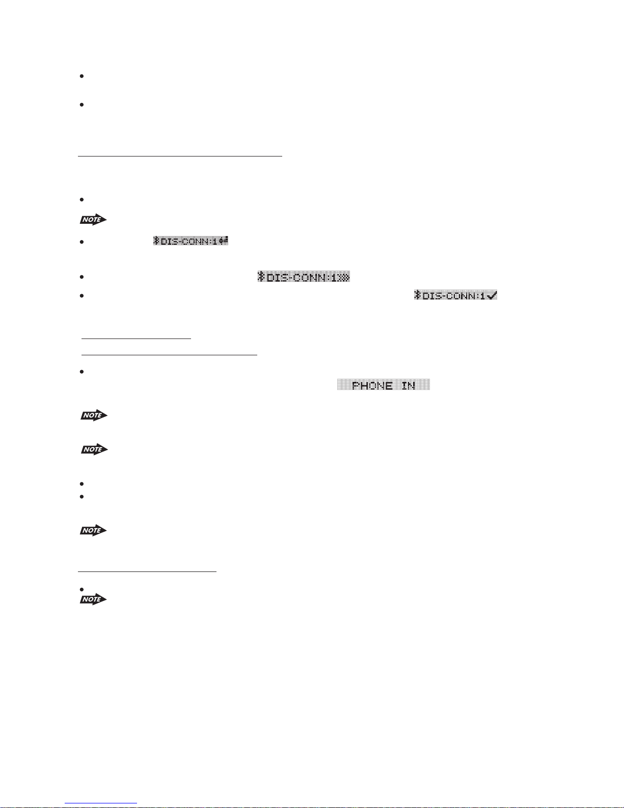
Once the “ ” is display on the LCD, press the AUDIO button to activate the
manual Dis-Connect mode.
The LCD Display will displayed “ ” during the Dis-connecting period.
If the Dis-Connection is successful, the LCD Display will display “ ”. And
the unit will switch back to the previous mode automatically.
INCOMING CALL
ANSWERING AN INCOMING CALL
When there is an incoming call, the display will display the Phone Number. If the incoming call
has no the Phone Number, the LCD will display “ ” User can press the
“PHONE” button or “MODE” button to answer / accept the call.
Always press the “PHONE” (AUIDIO)button or “MODE ' button to answer / accept the call
after the LCD display the Phone Number or “PHONE IN”.
The audio output of the present mode will be muted and the ringing tones will be heard, if
an incoming call is not being answered.
User can use the volume up/down to adjust the volume level.
To end the conversation, press the “CLEAR” button. The unit will switch back to the previous
mode automatically and release the mute of the previous mode at the same time.
An incoming call under stand by mode (Ignition on & Power Off) The system will
automatically switch on the head unit.
Rejecting An Incoming Call
User can press “CLEAR” button to reject the incoming call.
The audio output of the present mode will be muted and the ringing tones will be heard if an
incoming call is not being answered. After pressing the “CLEAR”(BAND) button, the mute
of the present mode will be released.
38
Page 40
OUTGOING CALL
Making An Outgoing Call
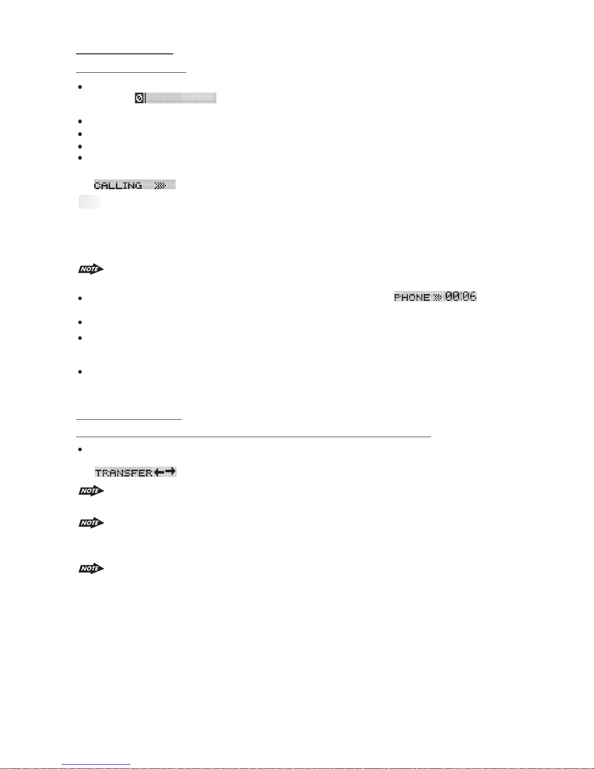
Press the “PHONE” (AUDIO)button to start making an outgoing call. The LCD Display will
display And a cursor will keep blinking while waiting the user to enter the
phone number.
Rotate the encoder knob to navigate thru the numeric 0-9 *, # & + .
Press the” AUDIO” button as confirm input the selected numeric.
Use the File up/down button to move the cursor back or forward to the wrong inpu numeric
Once the phone number has been entered completely, Long press the“PHONE” button again
or Short Press the “MODE” button to start dialing the call, the LCD Display will display “
”.
Tips
Under the Calling mode, if need to input any number, for example Pin Code Input or Service
Number Dial Input. Short press the “AUDIO” button to enter the numeric input interface
then rotate the encoder knob to navigate the desire input number and press the “AUDIO”
button again as confirm input the selected number. To exit the numeric input interface by
LONG PRESS the “AUDIO” button again.
The audio output of the present mode will ONLY be muted after pressing the “PHONE”
button as a confirmation to dial the outgoing call.
During the talking mode, the LCD Display will display the duration “ ”of the
conversation.
User can use the volume up/down to adjust the volume level.
To end the conversation, press the “Clear” button . The unit will switch back to the previous
mode automatically. The mute of the previous mode will be released at the same time.
During the talking mode, if the Ignition is being turned off, the unit will keep the conversation
even if the Ignition is Switched off. After finished the conversation, User can press “CLEAR”
button to switch off the unit.
CALL TRANSFER
TO AUDIO TRANSFER FROM HEAD UNIT BACK TO THE MOBILE PHONE
During the talking mode, user can press the “TRANSFER” button to transfer the audio from the
unit back to the mobile phone for privacy reason. The LCD Display will display “
” on the LCD for 3 seconds.
After the “Transfer” button is pressed, the mute of the present mode will be released at the
same time.
When making an outgoing call, it's not possible to CALL TRANSFER if the call is not being
answered yet.. It's only possible to Transfer the call to Mobile phone after the call is being
answered.
Depending on different type of Mobile Phone, the time need for activating the CALL
TRANSFER mode is different. Like Nokia Mobile Phone usually takes 3-5 seconds after
pressed the "TRANSFER” button for audio transfer back or forth through Unit to mobile
phone.
39
Page 41

DIALED LIST
To Find the Last 10 Dialed Number
The unit can memory up to 10 last dialed number.
Press the “PHONE” (AUDIO) button, after the LCD appeared display “ ”,
then Long press “PHONE” (AUDIO) button.
The last dialed number as the first number on the list will display on the LC D. Rotate the
encoder knob to navigate through the 10 last dialed number.
User can Long press the “PHONE” (AUDIO) button or Short press “MODE” button to confirm
dialing the selected Dialed Number from the list.
User also can be edit the number in the dialed list. Once the desired edit dialed list appearing
on the display, user can short press “PHONE” (AUDIO) button to enter the number edit mode.
Use the Track up/down button to move the cursor back or forward to the input numeric which
want to edit.
The unit only memorize the dialed numbers which dialed from the unit, it cannot memorize
the number dialing from the mobile phone.
HIGHLIGHT FEATURES
Incoming call ringing volume
Preset the Ringing volume level for any incoming call.
Please see “MENU”- “PHONE VOL” for details operation.
Auto Answer
Auto Answer any incoming call.
Please see “MENU”- “A ANSWER” for details operation.
40
Page 42
BLUETOOTH AUDIO STREAMING A2DP (ADVANCED AUDIO
DISTRIBUTION PROFILE)
User can listen to music files on an audio device on this unit if the audio device supports A2DP
(Advanced Audio Distribution Profile) of Bluetooth Technology. Please read the below
instruction before operating the Bluetooth Audio streaming function on this unit.
Connecting A Bluetooth Audio Device With This Unit
Before using audio device to play music on this unit, the audio device must be paired with this unit first.
a. For the details operation of Pairing with this unit, Please refer to the PAIRING
operation for more details.
b. How to use the Bluetooth audio device to pair with this unit, please referto the
instruction manual of the Bluetooth device.
Tips
Listening To Music From An Audio Device In This Unit
1) Connect this unit with the audio device.
If the audio device has both HFP (Hands Free Profile) and A2DP (Advance Audio
Distribution Profile), this unit will automatically pairing these two profiles at the same
time. For ex, if a mobile phone has both HFP & A2DP profile and this mobile phone is
already HFP paired with this unit, in this case A2DP audio device pairing is not
necessary. And this paired mobile phone will be added automatically to the list of
PAIRED DEVICE – AUDIO of this unit. Please refer to MENU of BT for details of
PAIRED DEVICE operation.
For the details operation of connecting with this unit, Please refer to the CONNECTING
operation for more details.
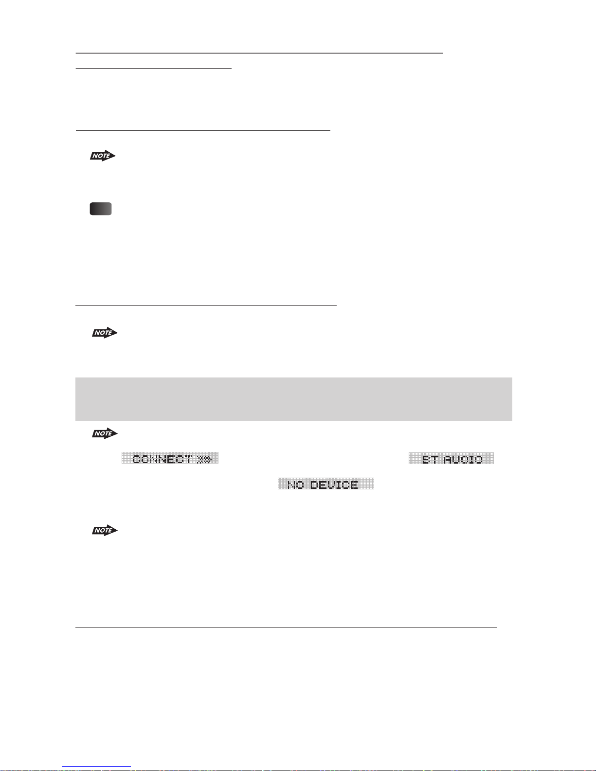
2) Press MODE button repeatedly until “BT AUDIO” appears on the display.
IMPORTANT: To listen Bluetooth audio streaming from the audio device, user MUST
change the mode to “BT AUDIO” first. Any other mode of this unit is not able to
activate the Bluetooth audio streaming ( A2DP ) function.
If the audio device is the connected or no audio device is connecting with this
unit, after mode changed to BT AUDIO mode, the display will show
If it can find Audio Device, it will display ,
and if after a 30 seconds time out still cannot find any audio device for
connecting, the unit will display . .
3) Once in the “BT AUDIO” mode, user can use the audio device to start playback the song via
Bluetooth wireless with this unit.
Operating an audio device with this unit AVRCP ( Audio Video Remote Control Profile )
This unit can perform the following operations with the connecting Audio device which supports
AVRCP (Audio Video Remote Control Profile) & only if the Audio device does support AVRCP.
When mode change to BT AUDIO mode, some of the audio device may auto
playback the music without operate the music playback operation and some of the
device like mobile phone may need to first change into the 'Media Player' mode on
the mobile phone otherwise the song cannot be direct playback via Bluetooth
wireless. If the auto playback is not supported on the audio device then please refer
to the instruction manual of the audio device on how to operate music playback via
Bluetooth wireless technology.
41
Page 43

1) Start playing-Every time when user change mode into “BT AUDIO” mode, this unit will
automatically send a “PLAY” command via AVRCP to the audio device to command the
auto start playing song in the audio device.
The PLAY command may differ depending on the Audio device. If the Audio device
is not able auto start playing song after changed mode into “BT AUDIO” mode, user
may need to operate the PLAY mode on the audio device to start the song playback.
2) Track up / down - by pressing the Track up / down buttons on this unit.
3) Pause / Play – by pressing the Pause / Play button on this unit.
4) Volume up / down – by rotating the encoder knob on this unit.
5) Audio Mute – by pressing the Mute button on this unit.
6) Stop playback – by mode changing mode into any other mode of this unit.
The AVRCP operation may differ depending on the audio device, all the other
operation other than those listed above should be performed on the audio device.
Hands-free Phoning While Bluetooth Audio Streaming
If the connecting playback audio device is a mobile phone, all the hands free function is still
available under the Bluetooth audio streaming, like the answering incoming call, making an
outgoing call, etc.
For some model of mobiles, maybe they cannot make outgoing calls. e.g: Samsung
SGH-D528.
Disconnecting An Audio Device With This Unit
User can close the Bluetooth Audio connection by disconnecting with the audio device.
The details operation of disconnecting with this unit, please refer to the DIS-CONNECTION
operation for more details.
42
Page 44
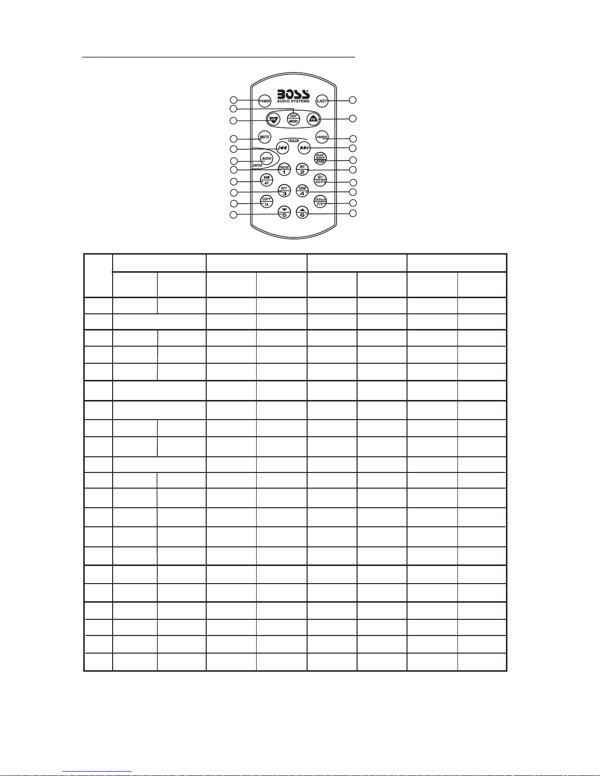
19 iPod RDS. REMOTE FUNCTION( + )
OPERATIONS:
SYST EM TUNE R MP3/W MA
KEY
Short
Press
MutePowe r
1
2
Display
3
Source
4
Mute
5
Long
Press
Menu
1
3
7
5
9
10
12
18
14
20
16
Short
Press
Long
Press
Short
Press
Panel release button
Enter
2
6
4
8
11
13
19
15
21
17
iPod
Long
Press
Short
Press
Long
Press
10
11
12
13
14
15
16
17
18
19
20
21
6
7
8
9
Volume Up
Volume Do wn
Audio Men u
Sub-W
Copy
ix-Ba ss
Seek Up
Seek
Down
Band
M1
M2
M3
M4
M5
M6
AF
PS
TA
PTY
Tune Up
Tune
Down
Memory 1
Memory 2
Memory 3
Memory 4
Memory 5
Memory 6
AS
USB Socket
Track/Fi le
Up
Track/Fi le
Down
Enter
File/Fo lde r
Search
Pause
/Play
Intro
Repeat
Random
Folder
Down
Folder
Up
ID3
Fast
Forward
Fast
Backwar d
File
Erase
Folder
Intro
Folder
Repeat
Fol der
Rando m
File Up
File
Down
Enter
iPo d
Search
Pause
/Play
Repeat
Shuffle
iPod
inf ormati on
Fast
Forward
Fast
Backwar d
Album
Repeat
Album
Shuffle
43
Page 45

20. SPECIFICATIONS
CD PLAYER
System
Usable disc
Sampling frequency
No of quantization bits
Frequency
Number of channels
S/N Ratio
MEDIA SECTION
USB Host
Memory Card
Support Type of Memory Card SD and MMC
RADIO SECTION
FM
Frequency Range
Intermediate Frequency
Usable Sensitivity
Stereo Separation
S/N Ratio
Compact disc audio system
Compact disc
44.1KHz
1bit
5-20,000Hz
2 stereo
70dB
Host 1.1 compatibles 2.0
87.5-108 Mhz
87.5-107.9Mhz
10.7 MHz
Better than 15dB at S/N 30 dB
25 dB at 1KHz
50 dB
AM/MW
Frequency Range
Intermediate Frequency
Usable Sensitivity
S/N Ratio
522-1620 KHz
530-1720 KHz
450KHz
Better than 45dB
40 dB
BLUETOOTH
Power Consumption
Output Power
Frequency Band
Range
Standard
200mA
0 dBm (Class II)
2.4GHz ~ 2.4835GHz ISM Band
3 meters (free space)
Bluetooth 1.2 specification
Max.
GENERAL
Power Supply
Polarity
Speaker impedance
Power Output
DC 11 -14V
Negative Ground
4 ohms
4 x 80W
REMARK :
Specifications subject to change without notice.
44
Page 46

21. TROUBLE SHOOTING
Before going through the check list, check wiring connection. If any of the problems persist after
check list has been made, consult your nearest service dealer.
Symptom
No power
Disc cannot be
loaded or ejected
No sound
The operation keys
do not work
Sound skips.
The radio does not
work.
The radio station
automatic selection
does not work.
ERROR 1
Write Error
Cause
The car ignition is not on.
The fuse is blown.
Presence of CD disc inside
the player.
Inserting the disc in reverse
direction.
Compact disc is extremely
dirty or defective disc.
Temperature inside the car is
too high.
Condensation.
Volume is in minimum.
Wiring is not properly
connected.
The built-in microcomputer is
not operating properly due to
noise.
The installation angle is
more than 30 degrees.
The disc is extremely dirty or a
defective disc.
The antenna cable is not
connected.
The signals are too weak.
Mechanism Error
The Media Device not able to
copy by the unit.
Solution
If the power supply is properly connected
to the car accessory terminal, switch the
ignition key to “ACC”
Replace the fuse.
Remove the disc in the player, then
put a new one.
Insert the compact disc with the
label facing upward.
Clean the disc or try to play a new one.
Cool off or until the ambient temperature
returns to normal.
Leave the player to off for an hour or so,
then try again.
Adjust volume to a desired level.
Check wiring connection.
Press the RESET button.
Front panel is not properly fixed into
its place
Adjust the installation angle to less
than 30 degrees.
Clean the compact disc or try to play a
new one.
Insert the antenna cable firmly.
Select a station manually.
Press the reset button to correct the problem.
If the error code does not disappear, consult
your nearest service dealer.
Replace the Media Device or
Read Error
Memory Full
No File
Disc Error
The Media Device not able to
play file by the unit
The media device memory is
full not allow to copy
No file Format supports for
Playback on the disc or
Media Device
Maybe disc dirty / disc scratched
/disc upside down.
If at any time in the future you should need to dispose of this product please note
that Waste electrical products should not be disposed of with household waste.
Please recycle where facilities exist. Check with your Local Authority or retailer for
recycling advice.(Waste Electrical and Electronic Equipment Directive)
Replace the Media Device or
Replace the Media device or erase
some un-usage files.
Replace the disc or Media Device..
Replace the disc.
45
Page 47
10 R - 02 1397
4
 Loading...