

Page 1

Page 2

CONTENTS LIST
PAGE CONTENTS
2 NOTEOFDISCS
3 ACCESSORY INCLUDED
4 INSTALLATION
6 DETACHABLE CONTROL PANEL
7 WIRING DIAGRAM
8 CONTROL PANEL FUNCTION
9 BASIC OPERATIONS
10 MENU OPERATION
11 AUDIO OPERATION
12 TUNER OPERATION
13 CD /MP3/WMA OPERATION
16 USB OPERATION
17 MEMORY CARD OPERATION
18 MUSIC FILES COPYING / TRANSFERRING
20 MUSIC FILES TRANSFERRING
22 FILES MANAGER
23 iPod OPERATION
25 BLUETOOTH HAND FREE OPERATION
37 REMOTE FUNCTION
38 SPECIFICATIONS
39 TROUBLE SHOOTING
1
Page 3

1. NOTE OF DISCS
MOISTURE CONDENSATION
On a rainy day or in a very damp area, moisture may condense on the lenses inside the unit.
Should this occur, the unit will not operate properly. In such a case, remove the disc and wait for
about an hour until the moisture has evaporated.
NOTES ON CDs
1.
A dirty or defective disc may cause sound
dropouts while playing. To enjoy optimum
sound, handle the disc as follows.
Handle the disc by its edge. To keep the
disc clean, do not touch the surface (P.1).
P. 1
2.
Do not stick paper or tape on the disc (P.2).
NOTES ON DISCS
If you use the discs explained below, the
sticky residue can cause the CD to stop
spinning and may cause malfunction or ruin
your discs.
Do not use second-hand or rental CDs that
have a sticky residue on the surface (for
example, from peeled-off stickers or from
ink, or glue leaking from under the stickers).
There are paste residue.
Ink is sticky (P.5).
P. 5
*******
*******
*******
Do not use rental CDs with old labels that
are beginning to peel off.
****
*******
P. 2
Do not expose the discs to direct sunlight or
3.
heat sources such as hot air-ducts, or leave
them in a car parked in direct sunlight where
there can be a considerable rise in
temperature inside the car (P.3).
P. 3
4.
Before playing, clean the discs with an
optional cleaning cloth. Wipe each disc from
the centre out (P.4).
P. 4
5.
Do not use solvents such as benzine,
thinner,commercially available cleaners, or
antistatic spray intended for analog discs.
Stickers that are beginning
to peel away, leaving a
sticky residue (P.6).
P. 6
**************
*******
*******
*******
Do not use your CDs with labels or stickers
attached.
Labels are attached (P.7).
*******
*******
*******
*******
*******
P. 7
Do Not Use Special Shape CDs
Be sure to use round shape CDs only for
this unit and do not use any special shape
CDs. Use of special shape CDs may cause
the unit to malfunction.(P.8).
P. 8
Be sure to use CDs with disc mark
RECORDABLE
REWRITABLE
TEXT
Only for this unit.
CD-Rs and CD-RWs which have not
undergone finalization processing cannot
be played. (For more information on
finalization processing, refer to the manual
for your CD-R/CD-RW writing software or
CD-R/CD-RW recorder.) Additionally,
depending on the recording status, it may
prove impossible to play certain CDs
record on CD-R or CD-RW.
2
Page 4
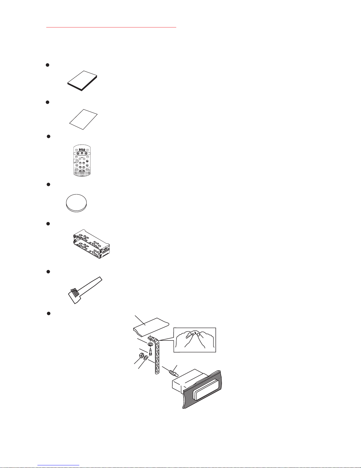
2. ACCESSORY INCLUDED
When first unpacking your new full detachable DVD head unit, please check first that the package
contains all of the items below. If something is missing, contact the store where you purchased
the player.
Owner’s Manual
Owner’s
manual
Warranty Card
Warranty
Card
Remote control
Lithium Battery
+
Lithium Cell
CR2025
3V
SC5
Half Sheeve
Insert Key
1. Dashboard
2. Nut (5mm)
3. Spring washer
4. Screw (4X12mm)
5. Screw
6. Support Strap
7. Plain washer
1
6
7
4
2
5
3
3
Page 5
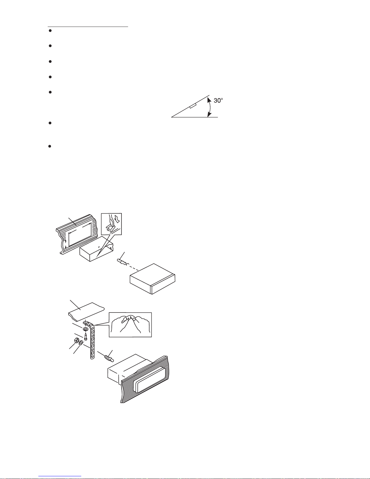
3. INSTALLATION
Before finally installing the unit, connect the wiring temporarily and make sure it is all
connected up properly and the unit and system work properly.
Use only the parts included with the unit to ensure proper installation. The use of
unauthorized parts can cause malfunctions.
Consult with your nearest dealer if installation requires the drilling of holes or other
modifications of the vehicle.
Install the unit where it does not get in the driver's way and cannot injure the passenger if
there is a sudden stop, like an emergency stop.
If installation angle exceeds 30° from horizontal, the unit might not give its optimum
performance.
Avoid installing the unit where it would be subject to high temperature, such as from direct
sunlight, or from hot air, from heater, or where it would be subject to dust dirt or excessive
vibration.
Be sure to remove the front panel before installing the unit.
DIN FRONT/REAR-MOUNT
This unit can be property installed either from “Front” (conventional DIN Front-mount)or“Rear”
(DIN Rear-mount installation, utilizing threaded screw holes at the sides of the unit chassis).
For details, refer to the following illustrated installation methods A and B.
DIN FRONT-MOUNT (Method A)
Installation the unit
1
2
182
53
3
1. Dashboard
2. Holder
After inserting the half sleeve into the
dashboard, select the appropriate tab
according to the thickness of the
dashboard material and bend them
inwards to secure the holder in place.
3. Screw
1
6
1. Dashboard
7
4
2
5
3
2. Nut (5mm)
3. Spring washer
4. Screw (4x12mm)
5. Screw
6. Support Strap
Be sure to use the support strap to secure
the back of the unit in place. The strap can
be bent by hand to the desired angle.
7. Plain washer
4
Page 6

Removing the unit
a
a. Frame
b. Insert fingers into the groove in the
front of frame and pull out to remove
the frame. (When re-attaching the
frame, point the side with a groove
b
c
Trim Plate Installation:
Push the trim plate against the chassis until it is fitted.
You must do this before you install the front panel, otherwise it can't be attached.
DIN REAR-MOUNT (METHOD B)
down wards and attach it.)
c. Insert the levers supplied with the
unit into the grooves at both sides of
the unit as shown in figure until they
click. Pulling the levers makes it
possible to remove the unit from the
dashboard.
Installation using the screw holes on the sides of the unit.
Fastening the unit to the factory radio mounting bracket.
2
4
5
3
2
5
1. Select a position where the screw
holes of the bracket and the screw
holes of the main unit become
aligned (are fitted) and tighten the
screws at 2 places on each side.
2. Screw
3. Factoryradiomountingbracket.
4. Dashboard or Console
5. Hook (Remove this part)
Note: the mounting box, outer trim ring,
and half-sleeve are not used for method
B installation.
5
Page 7
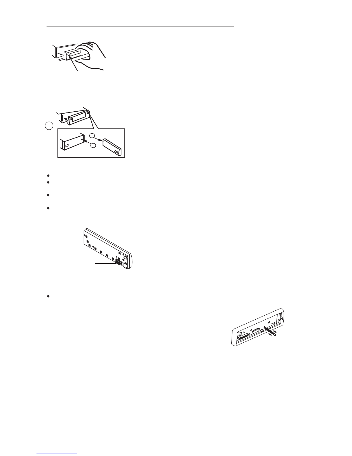
4. DETACHABLE CONTROL PANEL (D.C.P.)
Removing The Detachable Control Panel (D.C.P.).
1. Turn the power off
2. Press the D.C.P. release button
PANEL RELEASE
BUTTON
Attaching the DCP
3. Remove the D.C.P.
2
A
B
1. Attach the panel at the right side first, with
point B on the main unit touching point A on the
D.C.P. (As shown on the diagram).
2. Then press the left side of D.C.P. ontothemain
unit until a “click” sound is heard.
CAUTION
DO NOT inserttheD.C.P from the left side. Doingso may damage it.
The D.C.P can easily be damagedby shocks. After removing it, place it in aprotective case and be careful not
to drop it or subject it to strongshocks.
When the release button is pressed and the D.C.P is unlocked, the car's vibrations may cause it to fall. To
prevent damage to the D.C.P, always storeit in a protectivecase after detaching it.
The rear connector thatconnects the main unit and the D.C.P is an extremely importantpart. Be careful not to
damage it by pressing on it with fingernails,pens, screwdrivers, etc.
Note:
If the D.C.P is dirty, wipe off the dirt with soft, dry
cloth only. And use a cotton swab soaked in
isopropyl alcohol to clean the socket on the
Socket
back of the D.C.P.
RESETTING THE UNIT:
After releasing the front panel, use a pencil or any non-metalic object to press & hold the reset
button for five seconds to reset the unit.
RESET
6
Page 8
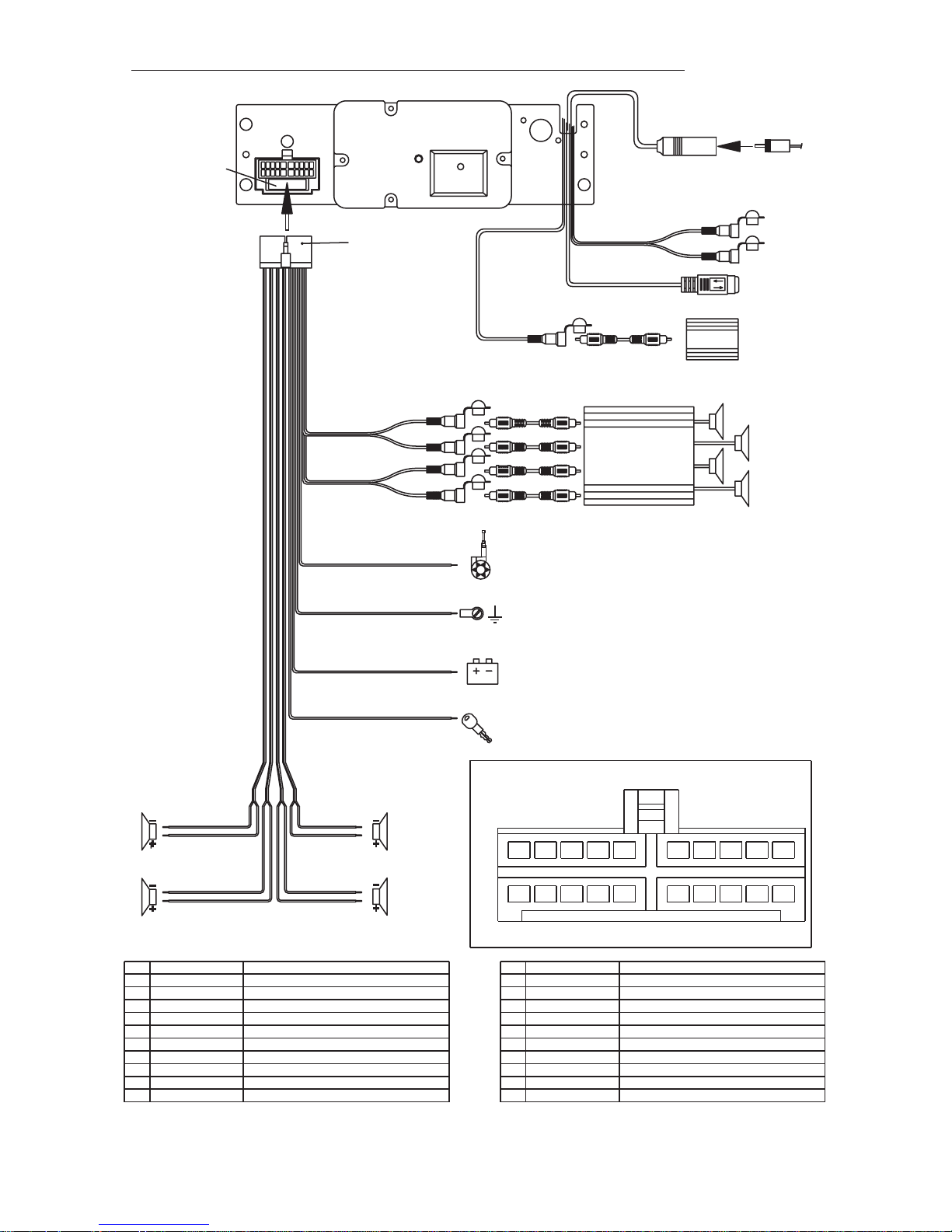
5. WIRING DIAGRAM (20 PIN HARNESS PLUG)
FUSE
20-PIN
AUDIO/POWER
HARNESS
(See Figure 1)
GREY
REAR LINE OUT
BLACK
FRONT LINE OUT
WHITE
WHITE
BLUE
RED
RED
L-CH
R-CH
L-CH
R-CH
BLUE
YELLOW
iPod ready cable(IPC40)
SUB WOOFER
WHITE
RCA-TO-RCA CABLES
(not supplied)
Power antenna wire that can also be used
for remote turn on lead.
RCA-TO-RCA CABLES
WHITE
(not supplied)
AMP
ANTENNA
JACK
WHITE
SUB-WOOFER
RED
ANTENNA
CABLE INPUT
R-CH
L-CH
iPod
AUX LINE IN
LEFT FRONT
WHITE-BLACK LF-
WHITE LF+
LEFT REAR
GREEN-BLACK LR -
GREEN LR+
WIRE COLOR
PIN
1 GREY/BLACK
2 GREY
3 VIOLET
4 VIOLET/BLACK
5
6 GREEN
7 GREEN/BLACK
8 RED
9 BLACK
10 RED
RIGHT FRONT
GREY-BLACK RF-
GREY RF+
RIGHT REAR
VIOLET-BLACK RR-
VIOLET RR+
RIGHT FRONT SPEAKER (-)
RIGHT FRONT SPEAKER (+)
RIGHT REAR SPEAKER (+)
RIGHT REAR SPEAKER (-)
LEFT REAR SPEAKER (+)
LEFT REAR SPEAKER (-)
IGNITION(ACC)
REAR PRE-AMP LINE OUT COMMON
RIGHT REAR PRE-AMP LINE OUT
FUNCTION/LABEL
BLACK
YELL
OW
RED
Ground Connect to ground terminal or
Clean unpainted metal part of
Memory/Battery
Connect to a constant 12 volt source.
The radio will not work if this wire is not connected.
Accessory/Ignition Connect to existing radio wire or radio fuse.
Figure 1
WIRE COLOR
PIN
11
WHITE
12
WHITE/BLACK
13
14
BLUE
15
YELLOW
16
BLACK
17
WHITE
18
RED
19
BLACK
20
WHITE
chassis
20-PIN AUDIO/POWER HARNESS
653412
79810
141311 12 15 16
LEFT FRONT SPEAKER (+)
LEFT FRONT SPEAKER (-)
POWER ANTENNA
BATTERY(+)
CHASSIS GROUND
LEFT FRONT PRE-AMP LINE OUT
RIGHT FRONT PRE-AMP LINE OUT
FRONT PRE-AMP LINE OUT COMMON
LEFT REAR PRE-AMP LINE OUT
FUNCTION/LABEL
201817 19
Pin View
7
Page 9

6. CONTROL PANEL FUNCTION
21
OPERATIONS:
SYSTEM TUNER
KEY
Short
Press
Power
1
2
3
4
Source
5
6
Encoder Volume
7
Sub-W
8
3
1
22
23
Long
Press
Audio
Menu
6
11 13
Short
Press
Band
8
5
18
4
Long
Press
9
207
12
14
CD/MP3/WMA
Short
Press
Eject
Panel release button
Enter
File/Folder
Search
15
Long
Press
File
Erase
16 17
10
Blue Tooth
Short
Press
Phone
Answer
Reject Call
End Call
19
Long
Press
Call
Transfer
24
2
Search
Short
Press
iPod
iPod
Long
Press
10
11
12
13
14
15
16
17
18
19
20
21
22
23
24
9
Copy
ix-Bass
Display
Mute
Menu
PS
M1
M2
M3
M4
M5
M6
Seek Up
Seek
Down
AS
Memory 1
Memory 2
Memory 3
Memory 4
Memory 5
Memory 6
Tune Up
Tune
Down
ID3
Pause
/Play
Intro
Repeat
Random
Folder
Down
Folder
Up
USB Socket
Track/File
Up
Track/File
Down
AUX-IN JACK
Folder
Intro
Folder
Repeat
Folder
Random
Fast
Forward
Fast
Backward
iPod
information
Pause
/Play
Repeat
Shuffle
File Up
File Down
Album
Repeat
Album
Shuffle
Fast
Forward
Fast
Backward
8
Page 10
7. BASIC OPERATIONS
3) PANEL RELEASE BUTTON (REL)
Press this button to remove the control panel.
1) POWER ON/OFF BUTTON ( )
Press POWER button or any other button on the front of the radio to turn the unit on. Press
POWER button again to turn the unit off.
22) MUTE BUTTON (MUTE)
Press the mute button momentarily to mute the audio volume, and "Mute" will flash in the
display. Press the mute button again to restore volume to the previous setting.
8) SUB-WOOFER (SUB-W)
Short press the SUB-W button to activate the Sub-woofer function On, and “Sub-woofer” will
appear on the LCD display for 3 seconds. press the SUB-W button again to turn off the Subwoofer function.
10) iX-BASS BUTTON (iX-Bass )
Short press the iX-Bass button to turn on the IX-Bass function, and the “X-BAS” icon will appear
on the LCD display. Press the iX-Bass button again to turn off the IX-Bassfunction.
5) SOURCE BUTTON (SOURCE)
Press SOURCE button to select a different mode of operation as indicated on the display
panel. Available modes include Tuner, CDP, USB Host, SD/MMC ,iPod, Built-in memory and
Aux Line In .
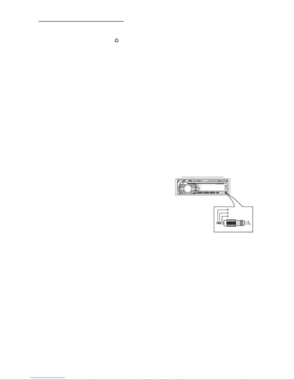
19) FRONT (AND REAR PANEL) AUXILIARY INPUT JACKS
This unit features AUX IN line input jacks on both the front (headphone type) and rear (RCA
type) panels.
PLEASE NOTE:
These two inputs cannot be used simultaneously. If
you have a source unit plugged into the rear panel
jack and wish to listen to a portable device (such as
an MP3 player) by using the front panel jack, be sure
to power off the unit plugged into the rear unit to
avoid interference.
Similarly, if you have a device plugged into the front
panel jack and wish to listen to the unit plugged into
the rear panel, be sure to turn off the front panel
device.
To select either the front or rear AUX IN device as a listening source, press the SOURCE button
to select AUX mode. Tocancel AUX IN listening, press SOURCE again.
AUX IN JACK IN PANEL
3.5mm AudioIn Cable (notincluded)
1
Left Audio
2
Right Audio
3
Ground
6) ENCODER VOLUME BUTTON
To increase the volume, rotate the volume control clockwise.To decrease the volume, rotate
the volume control counter clockwise. When volume is adjusted, the volume level will be
shown on the display panel as a number ranging from 0 (lowest) to 46 (highest).
9
Page 11
8. MENU OPERATION
23) MENU FUNCTION LIST (MENU)
Press MENU for more than 3 seconds to access the menu. Will appear in the display
momentarily. Navigate the menu by pressing MENU momentarily to move forward to the next
option. The menu can also be navigated by using the Tuning Up or Tuning Down Button to
move to the next or previous option. Oncethe desired option appears inthe display, adjust that
option by rotating the volume control within 5 seconds. The following options are adjusted
through this menu feature.
Pairing ( PAIR HF )
This feature is used to pairing the unit's Blue tooth system to your mobile phone or other Blue
tooth device. Under the MENU “Pairing” mode then press Audio button to start activating the
Pairing.
“PAIR HF” is special use for pairing with mobile phone with Bluetooth function, if the
pairing device is a Bluetooth Audio device, rotate the encoder to “PAIR AD” then
press Audio button to start activating the pairing with audio device.
Tips
Re-connection/Dis-connection (RE-CON / DIS-CON )
This feature is allows to Re-connect or Dis-connect to the paired mobile phone or Blue tooth
device by manually. Under the Menu- “RE-CON”mode, Rotate the encoder to navigate thru
“RE-CON” (re-connection) and “DIS-CON”(Dis-connection). After selected the mode for
connection then press Audio button to start activating the connection mode.
Incoming call ringing volume ( VOL)
The unit can preset the Ringing volume level for any incoming call. The default RINGING
VOLUME LEVEL VALUEis “20”. Rotate the encoder knob to adjust from Min 00 to Max 38.
Time Set ( CLK )
The time on the clock will be set to 12:00 as the default. Program the current time by rotating
the volume control clockwise to adjust the minutes and counterclockwise to adjust the hours.
Pls refer to BLUE TOOTH HAND FREE Operation regarding the details operation of
“PAIRING”.
BT
AREA (TUNER FREQUENCY SPACING)
This option allows the selection of the frequency spacing appropriate for your area. "AREA
U.S.A." is the default setting. Rotate the volume control to select the U.S.A. Latin America,
Europe or Oirt options.
Local / Distance Select
This feature is used to designate the strength of the signals at which the radio will stop during
automatic tuning. "Distance" is the default, allowing the radio to stop at a broader range of
signals. To set the unit to select only strong local stations during automatic tuning, rotate the
volume control until "Local" appears in the display.
Programmable Turn-on Volume ( P-VOL )
This option allows selection of the volume level the radio will automatically assume when first
turned on. "VOL PGM 12 " is the default setting, which will turn the radio on at the volume level
selected when the unit was last turned off.
To program a specific volume level for the radioto turn on at, rotatethe volume controlto select
"VOLUME LEVEL”. Within 5 seconds
Beep Tone ( BEEP)
The beep tone feature allows the selection of an audible beep tone to be heard each time a
button is pressed on the face of the radio. "BEEP TONE On" is the default display. Rotate the
volume control to select the "BEEP TONE Off" option.
10
Page 12

9. AUDIO OPERATION
Audio Menu
Long Press “AUDIO button to access the Audio Menu. User can navigate thru the Audio Menu
items by pressing the / “AUDIO” button repeatedly, or by pressing the Tuning Up or Tuning Down
Button. Once the desired menu item appears on the display, adjust that option by using the
Volume Up or Down button within 5 seconds. The following menu items can be adjusted as
described above. The unit will automatically exit the Audio Menu after five seconds of inactivity.
VOLUME (Volume Level)
User has 5 seconds to use the Volume button to adjust the desire volume level, the volume
level will be shown on the LCD display ranging from 00 (lowest) to 46 (highest).
BASS (Bass Level)
User has 5 seconds to use the Volume Up or Down button to adjust the desired Bass level
range from -6 to +6.
TREBLE (Treble Level)
User has 5 seconds to use the Volume Up or Down button to adjust the desired Treble level
range from -6 to +6.
BALANCE
User has 5 seconds to use the Volume Up or Down button to adjust the Balance between
the right and left speakers from R12 (full right) to L12 (full left). “C00” represents an equal
balance between the right and left speakers.
FADER
User has 5 seconds to use Volume Up or Down button to adjust the Fader between the
front and rear speakers from R12 (full rear) to F12 (full front). “C00” represents an equal
balance between the front and rear speakers.
”
11
Page 13

10. TUNER OPERATION
7) BAND BUTTON (BAND/SEARCH)
Press BAND to change between FM bands and AM(MW)bands.
20-21) TUNING UP/DOWN BUTTON ( )
Manual Tuning
Press the Up Tuning or Down Tuning button for more than 3 seconds to move the radio
frequency number up or down one step.
Auto Seek Tuning
Press the Up Tuning or Down Tuning button for less than 3 seconds to move to next station
automatically.
12-17) PRESET STATIONS BUTTONS
Six numbered preset buttons store and recall stations for each band.
Store a Station
Select a band (if needed), then select a station. Hold a preset button for 3 seconds. The
preset number will appear in the display.
Recall a Station
Select a band (if needed). Press a preset button to select the corresponding stored station.
11) AUTOMATICALLY STORE / PRESET SCAN (AS/PS)
Automatically Store
Automatically select 6 strong stations and store them in the current band. Select a band (if
needed). Press AS/PS button for more than three seconds. The new stations replace
stations already stored in that band.
Preset Scan
Scan stations stored in the current band. Select a band (if needed). Press AS/PS button for
less than 3 seconds. The unit will pause forten seconds at each presetstation. Press AS/PS
button again to stop scanning when the desired station is reached.
STEREO
The unit will automatically pick up a stereo signal, when available. When in stereo mode,
the ST icon appears in the display. When no stereo signal is available, the unit will
automatically revert to mono operation, and no icon will be displayed.
12
Page 14

11. CD /MP3/WMA OPERATION
INSERT AND EJECT CD
Insert a CD label-side up with the unit turned on, and the disc will begin to play. Press the Eject
button to stop CD play and eject the CD. The unit does not have to be turned on to eject the CD.
CD-DA OPERATION
12) PAUSE BUTTON
Press the pause button to suspend disc play. Press the pause button again to resume disc
Play.
20-21) TRACK SELECT
Press the Up Tuning or Down Tuning button ( ) for less than one second to advance
to the next track on the CD, The selected tracknumber will appear on the display. Press and
hold the Up Tuning or Down Tuning button ( ) for more than one second to fast
forward or fast reverse through the disc. CD play starts when the button is released.
14) REPEAT BUTTON (RPT)
Press REPEAT BUTTON (RPT) during disc play to continuously repeat the track. Press
REPEAT BUTTON (RPT) again to stop Repeating.
15) RANDOM BUTTON (RDM)
Press RANDOM BUTTON (RDM) during disc play to play all tracks on a CD in random,
shuffled order. Press RANDOM BUTTON (RDM) again to stop random play.
13) INTRO SCAN BUTTON (INT)
During disc play, press INTRO SCAN BUTTON (INT) to play the first 10 seconds to each
track on the disc. When the desired track is reached, press INTRO SCAN BUTTON (INT)
again to end the scan and play the selected track.
MP3/WMA OPERATION
MP3 and WMA (Windows Media Audio) music files are audio compression format. This unit can
play MP3/WMA directly from files contained on a CD-R/RW, USB Memory Stick, SD or MMC
Memory Card.
Notes on MP3/WMA Play
This unit can play MP3 (MPEG1, 2, 2.5 Audio Layer 3). However, the MP3 recording media and
accepted formats are limited. When writing MP3/WMA, pay attention to the following restrictions.
Acceptable Medium Formats
The following formats are available for the media used in this unit. The maximum number of
characters used for file name including the delimiter (".") and three-character extension are
indicated in parentheses.
ISO 9660 Level 1 (11 characters)
ISO 9660 Level 2 (31 characters)
Joliet (31 characters)
Romeo (31 characters)
Up to 200 characters can be displayed in the long file name format. For a list of available
characters, see the instruction manual of the writing software and the section “Entering File and
Folder Names” below. The media reproducible on this unit has the following limitations:
Maximum number of nested folders: 8
Maximum number of files per disc: 999
Maximum number of files per media device: 2000
Maximum number of folders per disc: 255
MP3/WMA written in the formats other than the above may not be successfully played and their file
names or folder names may not be properly displayed.
MP3/WMA Encoder and CD Writer Settings
Use the following settings when compressing audio data in MP3 data with the MP3 encoder.
13
Page 15

Transfer bit rate : 32- 320 kbps
Sampling frequency : 32,44.1,48 kHz(WMA) 16,22.05,24,32,44.1, 48kHz (MP3)
When using a CD writer to record MP3/WMA up to the maximum disc capacity, disable additional
writing. For recording onan empty disc up to the maximum capacity at once, check disc at once.
Entering ID3 Tag
This unit supports ID3 tag versions 1.0 and 1.1.
Entering File and Folder Names
Names using the code list characters are the only file names and folder names that can be entered
and displayed. Using any other character will cause the file and folder names to be displayed
incorrectly. The unit recognizes and plays only files with the MP3/WMA extension.
A file name entered with characters not on the code list may not play correctly.
Writing Files into a Media
When a media containing MP3/WMA data is loaded, the unit checks all data. If the media contains
many folders or non-MP3/WMA files, MP3/WMA play will be delayed, it may take time for the unit to
move to the next file, and searches may not be performed smoothly. Loading such a media may
produce loud noise and cause damage to the speakers. Do not attempt to play a media
containing a non-MP3/WMA file with the MP3/WMA extension or a media containing non
MP3/WMA files.
Bit Rates
The unit supports bit rates from 32 - 320 kbps.
Files Playing Order
When selected for play, Folder Search, File Search or Folder Select, files and folders are accessed
in the order in which they were written by the PC writer. Because of this, the order in which they are
expected to be played may not match the order in which they are actually played. For example, a
media with the following folder/file hierarchy is subject to Folder Search, File Search or Folder
Select as shown below.
An outline of a Media with MP3/WMA is shown below. Subfolders are shown as folders in the
folder currently selected.
ROOT
1 LEVEL 2 LEVEL 3 LEVEL 4 LEVEL
01
001.MP3
002.MP3
003.MP3
004.MP3
“NOT DISPLAY”
X
02
04
05
06
07
“NOT DISPLAY”
X
009.MP3
010.MP3
011.MP3
012.WMA
013.WMA
014.WMA
015.MP3
016.MP3
017.MP3
018.MP3
08
019.MP3
020.MP3
“NOT DISPLAY”
X
005.MP3
03
006.MP3
007.MP3
008.MP3
“NOT DISPLAY”
X
14
The equipment assigns folder
numbers. The user can not assign
folder numbers.
It is not possible to check folders
09
021.WMA
022.WMA
023.WMA
that do not include MP3/WMA files.
(These folders will be skipped
without displaying the folder
number and name)
Page 16

FILE/FOLDER PLAY
There are three different play methods as following:
File/Folder Intro play:
Press M2 button more than 3 seconds during playing MP3/WMA disc for “intro play” all files of
the current folder. Intro play should restart from the first songof the current folder, after all filesin
the current files have been intro-played.
To disable currentfolder “intro play”, long press M2 button more than 3 seconds
Press M2 button less than 3 seconds is “intro play” all files on the disc. Intro play should re-start
at the very first file of the disc after all files in the disc has been intro played.
To disable allfiles “intro play”, press M2 button less than 3 seconds
File/Folder Repeat play :
Press M3 button more than 3 seconds during playing MP3/WMA disc for “repeat play” all
files of the current folder. And keep on repeat playing the current folder until “repeat play” is
disabled.
To disable currentfolder “repeat play”, long press M3 button more than 3 seconds
Press M3 button less than 3 seconds to “repeat play” the current file. And keep on repeat
Playing the current file until the “repeat play” is disabled.
To disable currentfile “repeat play”, press M3 button less than 3 seconds
File/Folder Random play:
Press M4 button more than 3 seconds during playing MP3/WMA disc to “random play” all files
of the current folder.
To disable currentfolder “random play”, long press M4 button more than 3 seconds
Press M4 button less than 3 seconds is “random play” all files on the disc.
To disable allfile “ random play”, press M4 button less than 3 seconds.
Folder Up / Down Play
Press M5 button less than 3 seconds to One Folder Down
Press M6 button less than 3 seconds to One Folder Up
MP3/WMA File or Folder Search
Direct File Number Searching
Press BAND button. The LCD will display "Number", and the illumination around the select knob
will blink. Rotate the knob to select the desired track number, then press in on the knob to confirm
and play the selected file.
Folder / Files Navigate Searching
Press BAND button twice. The LCD will display "Navigate", and the illumination around the select
knob will blink. Rotate the knob to navigate through all folders and sub-folders on the disc. The
folder names will be displayed on the LCD. Press the select knob for more than three seconds to
play the first file in the folder. Press the select knob for less than three seconds to access the subfolders or files. Rotate the select knob to navigate, then press the select knob to confirm and begin
file play. During navigation search, press AS/PS or rotate the select knob counter-clockwise to
move back to the last upper level of a folder.
ID3 INFORMATION DISPLAY
If any MP3/WMA file recording with ID3 Tag information. The ID3 information such like Album title,
Track title, Artist Title will be displayed and automatic scrolling through the LCD while the file is
playing. User also allows pressing the AS/PS button repeatedly to view the ID3 tag information
manually.
15
Page 17

12. USB OPERATION
The unit can support USB Host Function. It can playback MP3 and WMA Audio format which are
stored into USB Memory Stick or USB interface Music Player. Please read below before you start
the operation of USB HOST Function.
Inserting and Removing USB Drive
Mini USB
to
Inserting the USB stick
big USB
extension
1
2
Warning:
Never Detach the Panel when a
USB stick was plug on the socket
cable
1
Mini USB to
big USB
extension cable
Always remove the USB stick before detach
the panel
Under any other mode while inserting a USB Stick into the front panel USB plug, the unit will
Automatically switches from present playing mode to USB HOST mode. The unit will display ‘
for a while then starts the files contained on the USB Stick.
Once the unit read the USB Stick successfully, the first audio music file on the USB stick
Playback will Automatically start. Press Mode button repeatedly to change to other modes or
switch back to USB HOST.
2
WARNING:
Before remove the USB stick from the Front panel USB plug. Always remember to switch off the
unit's power or switch to other mode then remove out the USB Stick. Never try removing the USB
Stick while playing music file on the USB stick. It may damage the USB Stick and sometimes will
caused the unit system lock up.
The unit can support playback Music Player which have USB Interface. However due to the
fast changing decoder technology and different kind of hardware interface. This unit may
or may not be compatible to all the Music Player andUSB Stick especially those USBStick /
Player which require to install a program driver.
About Music Flash Player with USB Interface, Usually, the unit takes longer time to read this
kind of player than normal USB Stick. Especially, if the Flash Player with built-in power
battery sometimes takes 20-30 seconds to start up the playback
The unit is not compatible to playing any Portable Hard disk.
Music File Playback Operation
All the USB playback operation function is same as the operation on CD/MP3/WMA. Please refer
to 'CD/MP3/WMA Operation' for more details.
16
Page 18

13. MEMORY CARD OPERATION
The unit can support playback MP3 and WMA Audio format which are stored into and
Memory Card . Pls read below before you start the operation of Memory Card
Inserting and Removing a SD or MMC card on the main unit
SD MMC
1
Detach the
Front Panel
1
Detach the
Front Panel
2
Face
Up
Insert the Memory Card
Push in till heard a “click”
3
Click
with Label up side
Inserting the SD or MMC card
2
Click
3
Push in till heard a “click” Remove the Memory Card
Removing the SD or MMC card
Mode change to MEMORY CARD
After a SD or MMC card was inserted into the main unit card slot. Press Mode button to select
Mode .The unit will display for a while then starts
The files contained
on the Memory Card. Once the unit read the MEMORY
CARD successfully,
the first audio music file on the Memory Card will automatically start playback. Press Mode
Button repeatedly is allowing changing to other modes or switch back to
Mode.
If no any Memory Card is inserted into the main unit card slot. Press mode button will
automatically skip mode.
Music File Playback Operation
All the SD or MMC Memory Card playback operation function is same as the operation on
CD/MP3/WMA. Pls refer to 'CD/MP3/WMA Operation' for more details.
17
Page 19

14. MUSIC FILES COPYING / TRANSFERRING
Thanks for the most useful and convenient files transferring function of this unit, user can easily
transfer music files between USB Stick, SD or MMC Memory card and on the CD Disc. Please
read below for the details operation of this function:
TRANSFERABLE MEDIA
Files are transferable within the following media:
Removable USB Stick
SD Memory Card
MMC Memory Card
File on the CD disc
MUSIC FORMAT SUPPORTED BY FILE TRANSFER ARE
MP3 and WMA
TRANSFER MP3 OR WMA MUSIC FILES ON CD DISC
This operation only can be performed during disc playing a MP3 or WMA music file.
1.Playback a music file to be transferred and then long press the COPY button to activate the
Transfer mode.
2.The LCD will display as default, Rotate the encoder volume knob to navigate
thru > for selection of the storage media.
3. Once selected the storage media, Press AUDIO button as confirmation to transfer the
Playing file. If no further button is press within a 10 second time out, the unit will automatically
resume to the previous mode
4.If the unit detected the selected media memory capacity is used up,
Will be displayed on the LCD for a while then automatically resume to the previous mode.
5.After pressing AUDIO button to start the transfer, the playing music file will stop and the
transferring will start at the same time. (The following step is an example of if selected
USB)
6.When the transfer is processing, the LCD will displayed .
7.When the file transfer is completed, the LCD will display for a while and
automatically playback the present music file which have been transferred. The transferred
music file is automatically saved as a file into Folder “MY_MP3” or “ MY_WMA” by the
advance “File Management.” system of this unit.
Tips
For more details information of File Management system of this unit. Pls see “FILE
MANAGER’’.
Under transferring mode, All the MP3/WMA operation is not functional, like file up / down,
Repeat, Random, and Intro etc.
The audio will remain recording by the unit system even MUTE function is activated
The Transferring will automatically stop if the storage device memory is less than 2MB
To Cancel Transferring.
1.Long press button COPY again to cancel the recording. The LCD will display
The music file that has been transferred incompletely will be deleted.
The unit will stop the file transfer automatically under the following operation,
the music file that has been transferred incompletely will be deleted.
1)Switch the power to off mode
2)Mode change
3)Inserting a CD Disc
4)Inserting a USB Stick
18
Page 20

TRANSFER MP3 OR WMA MUSIC FILES BETWEEN MEDIA DEVICES
Select a device by mode button and playback the music file need to be transfer:
1.Long press the COPY button to activate the transfer mode.
2.The LCD will display as default, Rotate the encoder volume knob to navigate
thru > for selection of the storage media.
3.Once selected the storage media, Press the AUDIO button as confirmation to transfer the
Playing file. If no further button is press within a 10 second time out, the unit will automatically
resume to the previous mode.
4.If the unit detect the selected media memory capacity is used up,
will be displayed on the LCD for a while then automatically resume to the previous mode.
5.After pressing AUDIO button to start the transfer, the playing music file will stop and the
transferring will start at the same time. (The following step is an example of if selected USB)
6.Under transfer is processing, the LCD will display .
7.When the file transfer is completed, the LCD will display for a while and
automatically playback the present music file which have been transferred. The transferred
Music file is automatically saved as a file into the Folder “MY_MP3 “ or “MY_WMA” by the
advance “File Management.” system of this unit.
Tips
For more details information of File Management system of this unit , Please see “FILE
MANAGER’’.
Under transferring mode, All the MP3/WMA operation is not functional, like file up / down,
Repeat, Random, and Intro etc.
The audio will remain recording by the unit system even MUTE function is activated
The Transferring will automatically stop if the storage device memory is less than 2MB
WARNING:
1) Never remove the USB Stick while recording or file transferring to USB Stick. It may damage
the USB Stick and sometimes will caused the unit system lock up.
2) It is not recommended to insert USB stick while recording is under progress to other
storage device. Always remember to stop the recording or after the recording is completed,
then insert the USB stick.
3) Do not switching mode of the unit during the File Transferring .
4) Do not turn off the Power of the unit during the File Transferring.
5) Do not switch the ignition key off during the File Transferring
19
Page 21

15. MUSIC FILES ERASING
You can erase files from the USB Stick or Memory Card Please read below for the details
operation of this function:
ERASABLE MEDIA
USB Stick and Memory Card.
Music files which are on the CD Disc is NOT ERASABLE
ERASING MUSIC FILES ON THE MEDIA
There are THREE different methods for erasing files;
1.Erase while the Music File is playing.
Long press BAND button to activate the ERASE mode
The LCD will display .
Short Press the AUDIO to enter into the ERASE mode.
Once enter into the erase mode. You can rotate the encoder volume knob to select “ ”
as to confirm the erase or rotate the volume knob to select “ ” as for cancel the erase
mode. If no further button is press within 5 seconds time out. The unit automatically resume
to the previous mode.
Once the “ ” is display on the LCD, press the AUDIO button again to final confirm
erase the present playback music file.
If want to CANCEL the erase of the present music file, Rotate the encoder volume knob
to “ ”. Once the “ ” is displayed on the LCD, press the AUDIO button again to cancel
the erase mode.
After pressing AUDIO button to start the ERASE, the present playing music file will stop
and the erasing will start at the same time.
will display on the LCD after the music file erase is successful, and the
unit will automatically start playback the next music file.
By this unit.
2.Erase under Files Number Search Mode
User can select the Music file Number want to erase by file Number Search mode
After selected the file number want to erase, Long press the BAND button to activate the
ERASE mode.
The LCD will display .
Short Press the AUDIO to enter into the ERASE mode
Once enter into the erase mode. User can rotate the encoder to select “ ” to confirm
the erase or rotate the volume knob to select “ ” to cancel the ERASE mode. If no further
button is press within a 5 second time out. The unit automatically resume to the previous
mode.
Once the “ ” is displayed on the LCD, press the AUDIO button to final confirm to erase
the selected music file.
If want to CANCEL the erase of the present music file, Rotate the encoder to “ ”.
Once the “ ” is display on the LCD, press
Mode.
After pressing AUDIO button to start the ERASE, the present playing music file will
Stop and the erasing will start at the same time
will display on the LCD after the music file erase is successful, and the
Unit automatically start playback of the next music file.
the AUDIO button again to cancel the erase
20
Page 22

3.Erase under Files NAVIGATE search mode
You can select a Music file want to erase by files Navigate Search mode
After selected the music file want to erase by files navigate search, Long press BAND
button to activate the ERASE mode.
The LCD will display .
Short Press the AUDIO button to enter into the ERASE mode
Once Enter into the ERASE mode, user can rotate the encoder to select “ “ as to confirm
the erase or rotate the volume knob to select “ ” to cancel the ERASE mode. If no further
button is press within a 5 second time out. The unit will automatically resume to the previous
mode.
Once the “ ” is displayed on the LCD, press the AUDIO button again to final confirm
Erase the selected music file.
If want to CANCEL the erase of the present music file, Rotate the encoder to “ “
Once the “ ” is display on the LCD, press the AUDIO button again to cancel the
erase mode.
After pressing AUDIO button to start the ERASE, the present playing music file will stop
and the erasing will start at the same time.
will display on the LCD after the music file erase is successful
and the unit will automatically start playback of the next music file.
WARNING:
1) Do not switching mode of the unit during the Erasing
2) Do not turn off the Power of the unit during the Erasing
3) Do not switch the Ignition key off during the Erasing
4) Do not detach the front panel during the Erasing
21
Page 23

16. FILES MANAGER
The advance “File Management.” System of this unit can help to well you organize all the music
files just like a PC . Pls read below for details:
FOLDERS MANAGEMENT
This unit will automatically self-create the below default folders onto any USB /SD / MMC media
device, once these devices are inserted into the unit.
MY_CD : Folder for saving all the music files source from CD Disc
MY_MP3: Folder for saving all the MP3 music files transfer from other device
MY_WMA: Folder for saving all the WMA music files transfer from other device
MY_AUX : Folder for saving all the music files source from AUX Line In
MY_iPod: Folder for saving all the music files source from iPod Player
FILES MANAGEMENT
This unit will automatically self-create the file name following with the Folder Name, for example:
Music file which recorded from CD disc, the file name ‘ will be automaticallyCD0001.MP3'
created & saved in the respective folder.
22
Page 24

17. iPod OPERATION
This unit is equipped with iPod Ready function which allow end user to have direct control of the
iPod on the front panel control button and display iPod song information on the unit's LCD display.
Pls read below for more details operation
iPod Compatibility Chart
This unit is support following iPod software version
iPod 1G Not Supported
iPod 2G Not Supported
iPod 3G Firmware Version 2.2
iPod Mini All versions
iPod 4G All versions
iPod Photo All versions
iPod Nano All versions
iPod 5G(Video) All versions
Connect the iPod to this unit
8 Din iPod Ready Cable
HEAD UNIT
iPod
photo
iPod iPod
(iPod Cable Sold Separately)
mini
iPod
nano
iPod Cable
About Video File
This unit is to select any VIDEO FILE OR VIDEO ALBUM which contained in the iPodNOT ABLE
Video. This unit will only automatically select Music Album or File regardless the connected Video
iPod last playing is a Video File or Album.
Turning iPod Power On and Off
The iPod power turns on automatically as soon as it is connected to the 30 Pin Connector and as
long as the vehicle's ignition is turned ON. The iPod power can be turned OFF by removing the
iPod from the 30 Pin Connector or if the vehicle's ignition is turned OFF. Under this condition the
iPod will go into pause mode and goes into sleep mode about 2 minutes later
While the iPod is connected, the power cannot be turned on or off from the iPod itself.
Tips
“ ” to disconnect will be shown in the iPod's display while it is connected to the unit .
OK to disconnect
iPod Battery Charging
While connected to the unit, the iPod will automatically start re-charging as long as the vehicle's
ignition key is turn to ACC or ON.
Switch to iPod Mode
When the Head unit is power on and iPod is connected to the 30 pin connector, press the
mode button to change to iPod mode and the unit will display for a while then
starts the music files contained in the iPod and the playback will automatically
start. Press Mode button repeatedly to change to other modes or switch back to iPod mode.
23
Page 25

iPod information Display on the Head Unit LCD
This unit can display the Song, Artist, Album name and Elapsed time on the LCD display, these
information can be displayed by pressing the AS/PS button repeatedly while a iPod Song file is
playing
Searching a Desire Song
Under iPod playback mode, press BAND to enter into the iPod Searching Mode. Pressing BAND
button repeatedly to accesses the different searching methods as below :
1) Playlist
2) Artist
3) Album
4) Song
5) Genre
Once selected the desire searching method, within 10 second press the AUDIO button as
confirm & access into the searching mode, then turn the rotate encode volume knob to
navigate thru the Album or Artist or Song contained in the iPod. Press the AUDIO button to
confirm & play the selected song. During the searching mode, press AS/PS as quick move
back to the last upper level of Album, Playlist, Genre, etc.
Song Select
Press the Track UP (>>) or Track DOWN (<<) button for less than one second to skip to the next
or previous song. Press and Hold Track UP (>>) or Track DOWN (<<) button for more than 3
seconds to fast forward or fast reverse of the current song.
Song Repeat / Repeat All play :
Long press the M3 button for more than 3 seconds during iPod playback mode for “REPEAT ALL”.
All songs of the current album will be kept on repeat playing until the “Repeat All” function is
disabled. To disable current Album “REPEAT ALL” function, long press M3 button more than 3
seconds
Press the M3 button for less than 3 seconds to “REPEAT PLAY” the current song. And keep on
repeat playing the current song until the “REPEAT PLAY” function is disabled. To disable current
song “REPEAT PLAY”, press the M3 button less than 3 seconds
Shuffle play: / Shuffle Album
Long press the M4 button for more than 3 seconds during iPod playback mode to activate the
“SHUFFLE ALBUM” function.
on the iPod.
To disable “SHUFFLE ALBUM” function, long press M4 button for more than 3
This function allows RANDOM playback of all the albums contained
seconds.
Press the M4 button for less than 3 seconds during iPod playback mode to activate “SHUFFLE
PLAY”. This function allows the playback of all the songs in the iPod in random sequence. To
disable “SHUFFLE PLAY”, short press M4 button again for less than 3 seconds.
24
Page 26

18. BLUETOOTH HAND FREE OPERATION
User Guide For Bluetooth Operation
1. When user use our Bluetooth HEAD UNIT, please make sure the mobile phone you use must / does support
Bluetooth functions (Headset or Handsfree profiles or both)
2. Before you start to use our Bluetooth HEAD UNIT, please make sure complete pairing with your mobile phone
first. Please refer to the user manual, section “PAIRING” for detail “PAIRING” instruction. To ensure the best
reception for Pairing or Re-connection, please make sure the Phone Battery is fully charged when making the
Pairing or Re-connection.
3. Please always try pairing the Mobile Phone with Head unit after a few minutes of the Mobile Phone was
Switched On to ensure the best pairing result.
4. “BT60” is this unit device model number which is displayed on the mobile phone.
5. Toachieve the best performance, please always keep the MobilePhone within 3 metersof the Head unit.
6. Please always keep a clear path between the Mobile Phone & the Head unit.
7. Never put any metal object or any obstacle between the path of the Mobile Phone & the Head unit.
8. Some brand of Mobile Phone like Sony Ericsson may have "Power Saving Mode" selection when Bluetooth
mode is switched on. Switches ON Power saving Mode whenoperating with this Head Unit, as
some abnormal communication behavior will happen occasionally ifPower Saving Modeis switched on.
9. Before user make Outgoing call or Incoming call, make sure the mobile phone's “Bluetooth function” was
switched “ON”.
10. To ensure the best conversation quality / performance, please always keep talking within 1 meter of the
Head Unit.
11. If user want to Dis-connect the Head unit with the Mobile Phone, please switch "OFF" Bluetooth connectivity
on the Mobile Phone,or go to the system menu, "dis-connect" to disconnect the Bluetooth connectivity manually.
( please refer to the user manual, section"dis-connection of the Bluetoothsystem for details instruction.)
12. Some Mobile Phones can support “IN BAND RING TONE”, such as Nokia. In such case, the Incoming
Ringing Tone will be same as the original Ring-tone of the Mobile Phone. But some Mobile Phones like Sony
Ericsson do not support this feature. The Ring-tonewill be using thestandard Ring-tone of the Head unit.
13. When in telephone mode, during talking, it is highly recommended to set the volume to below 30 in
order to achieve the best sound quality. As if the volume is too high, it may create unwanted echo inside
the car, and this unwanted echo may feedback intothe microphone.
14. If the Bluetooth related operation is not performing normally, like cannot make pairing, cannot making an
outgoing call, User can try to make a SOFT-RESET of the Bluetooth module by removing / detaching the panel
from the main unit and waiting for about 1 min. Then re-attach the panel tothe unit & retry the Bluetooth operation
again. Or user can RESET the whole unitby pressing the RESETbutton behind the panel.
By pressing the RESET button all the stored memory will resume to factory default
PLEASE DO NOT
FAQ (Frequency Asking Questions)
Q: Under phone conversation, if the voice outputfrom the car's speakersis not loud enough.
A: Try increase the volume level of the head unitto a suitable soundlevel
Q: Under phone conversation, the “Listener” cannot hearingmy voice loud enough
A: First, try asking the 'Listener” increase the volume level on his/her mobile phone, if still not loud enough, try to
increase your mobile phone's volume.
Q: Under Phone conversation, the “Listener' can hearecho feedback.
A: Your unit's speaker volume level is too loud which cause the voice feedback into the built-in microphone,
this can be corrected by decreasing the volume level.
Q: Under Phone conversation, the “Listener' complain thebackground is too noisy
A: May be you are in a noisy environment. Try close the car's window to shield the environment / background
noise under phone conversation.
Q: If the Mobile Phone already paired with the headunit, but after several calls, the incoming calls cannot access
thru the headunit.
A: May be the paired Mobile Phone lost the Bluetooth connection with the headunit. in this case, please go to the
"MENU" & select "re-connect" to reconnect the headunitwith the paired Mobile Phone. For details,please refer
to the MENU operation "re-connection”.
25
Page 27

Bluetooth Mobile Phone Compatibility List
This unit can support Bluetooth specification v1.2 or higher, and compatible with Bluetooth profiles such
as handsfree or headset profiles. however the functionality may be limited due to some phones' own
dedicated interfacing specification.
This list is only updated to the time this list is being printed. This list gives an example of Bluetooth mobile
phone available on the market, if your Bluetooth mobile phone is not on the list, please tryit out in practice
or try your phoneat the local dealer or consult withthe local dealer in case it isnot mentioned in the list.
1. Sony Ericsson
Features
Caller ID
Pairing
Ringing
Talking
Dialing
Features
Caller ID
Pairing
Ringing
Talking
Dialing
Pairing
Pairing cancel
In-Band Ring Tone
Talk
Reject
Audio Transfer
Volume up/down
Hang up
Audio Transfer
Volume up/down
Redial last call
Pairing
Pairing cancel
In-Band Ring Tone
Talk
Reject
Audio Transfer
Volume up/down
Hang up
Audio Transfer
Volume up/down
Redial last call
Z600
(Advance)
Z800i
#1
Z600
(Save mode)
W800i
T630
(Advance)
W550i
(Advance)
T630
(Save mode)
W550i
(Save mode)
K700i
W810i
S700i
26
Page 28

2. Nokia
Features
Caller ID
Pairing
Ringing
Talking
Dialing
Features
Caller ID
Pairing
Ringing
Talking
Dialing
Pairing
Pairing cancel
In-Band Ring Tone
Talk
Reject
Audio Transfer
Volume up/down
Hang up
Audio Transfer
Volume up/down
Redial last call
Pairing
Pairing cancel
In-Band Ring Tone
Talk
Reject
Audio Transfer
Volume up/down
Hang up
Audio Transfer
Volume up/down
Redial last call
8910
6111
6600
6230i
6230
7380
N90
7600
N91
27
Page 29

3. Motorola
Features
Caller ID
Pairing
Ringing
Talking
Dialing
Pairing
Pairing cancel
In-Band Ring Tone
Talk
Reject
Audio Transfer
Volume up/down
Hang up
Audio Transfer
Volume up/down
Redial last call
4. Panasonic & Sharp
V600
E398
V501 V3
V80
V3X
Features
Caller ID
Pairing
Ringing
Talking
Dialing
Pairing
Pairing cancel
In-Band Ring Tone
Talk
Reject
Audio Transfer
Volume up/down
Hang up
Audio Transfer
Volume up/down
Redial last call
Panasonic X88
GX-T15 GX-T71
28
Page 30

5. Siemens & BenQ
Features
Caller ID
Pairing
Ringing
Talking
Dialing
Pairing
Pairing cancel
In-Band Ring Tone
Talk
Reject
Audio Transfer
Volume up/down
Hang up
Audio Transfer
Volume up/down
Redial last call
S55 S88
6. Dopod & MIO & Blackberry
818
Features
Caller ID
Pairing
Ringing
Talking
Dialing
Pairing
Pairing cancel
In-Band Ring Tone
Talk
Reject
Audio Transfer
Volume up/down
Hang up
Audio Transfer
Volume up/down
Redial last call
565
A700
8700
29
Page 31

7. Samsung & LG
Features
Caller ID
Pairing
Ringing
Talking
Dialing
Pairing
Pairing cancel
In-Band Ring Tone
Talk
Reject
Audio Transfer
Volume up/down
Hang up
Audio Transfer
Volume up/down
Redial last call
D508
D528
KG320
30
Page 32

Bluetooth Hand Free Panel Function Key Matrix
3
4
1
Panel Function Button
1
PHONE/AUDIO ( Short Press )
2
Bluetooth Hand Free Function
Confirm to answer an incoming call
1. Reject Incoming call
2
CLEAR/BAND ( Short Press )
2. End a call
3
4
MODE ( Long Press )
MENU ( Short Press )
Transfer Phone Conversation back to
Mobile Phone
Pairing / Re-Connection etc
Note: See Menu operation for more details.
31
Page 33

PAIRING
Pairing The Bluetooth System Between User’s Mobile Phone & The Unit
Access into MENU - PAIRING mode to activates the operation of Pairing .
Please see MENU Operation for more details of how to access into MENU mode .
Once the is appearing on the LCD Display, press the AUDIO button to
activate the Pairing mode.
Keep the Mobile Phone within 2 meter from the unit when making the pairing.
To terminate the pairing, you can press the “CLEAR / BAND” button at any time.
Select the Bluetooth set up on the Mobile Phone.
Please refer to the instruction manual of your Mobile Phone on how to enter into the
Bluetooth set up and Blue tooth on / off, and blue tooth pairing.
“BT60” should appear in the pairing list on the Mobile Phone. User need to select “BT60”
and then input the password
If the pairing is successful, the display will show Mobile Phone Name or Model Number.
If the pairing failed, “ ” will be flashing on the Display for 3 seconds. And
the unit will switch back to the previous mode automatically.
During the Pairing, only Power, Clear ,Volume +/- & Mute are functional, other function
keys are disabled & non-operational during the pairing mode.
“1234”.
Re-Connection Of The Bluetooth System
The unit is with built -in Auto-Reconnection function. In some conditions, user need to reconnect
manually. For example like the following.
If The Mobile Phone is out of range.( 2 meters away from the Head unit) Under the condition of
lost connection when the user come back to the unit. At the same time, there is an incoming
call or user is under conversation on the Mobile Phone 2 meters away from the Head Unit and
come back to Head unit.
If user wants Audio Transfer back from Mobile Phone to Head unit. It needs to re-connect
manually.
The unit can be re-connected by the following methods.
Access into MENU - RE-CON mode to activate the manual RE-Connection.
Please see MENU Operation for more details of how to access into MENU mode.
Once the is display on the LCD , press the AUDIO button to activate the
manual Re-Connect mode.
1.Keep the Mobile Phone within 2 Meter from the unit when making the connection.
2.The manual re-connect is only function with the Mobile Phone has already been paired
with the unit before.
The LCD Display will displayed “ ” during the connecting period.
If the re-connection is successful, the LCD Display will display “ ”. And the unit will
switch back to the previous mode automatically.
If the re-connection failed, the LCD Display will display “ ” . And the unit will
switch back to the previous mode automatically.
32
Page 34

The unit will be Auto Re-Connection by following operation .
Every time turn the ignition key from off to on, the unit will Auto re-connect with the Mobile
Phone.
Dis-Connection of the Bluetooth System
The unit have a option function for user to disconnect the Bluetooth system with the unit.
The unit can be Dis-connected by the following methods.
Access into MENU - DIS-CONN mode to activate the manual Dis-Connection.
Please see MENU Operation for more details of how to access into MENU mode.
Once the “ ” is display on the LCD, press the AUDIO button to activate the
manual Dis-Connect mode.
The LCD Display will displayed “ ” during the Dis-connecting period.
If the Dis-Connection is successful, the LCD Display will display “ ”. And the unit will
switch back to the previous mode automatically.
INCOMING CALL
ANSWERING AN INCOMING CALL
When there is an incoming call, the display will display the Phone Number. If the incoming
call has no caller number, the LCD will displa user can short press the
( Audio ) button answer / accept the call.“PHONE”
Always press the (AUIDIO) button answer / accept the call the LCD
display the “ Incoming caller telephone number ”.
The audio output of the present mode will be muted and the ringing tones will be heard,
if an incoming call is not being answered.
User can use the volume up/down to adjust the volume level.
To end the conversation, press the “CLEAR / BAND” button. The unit will switch back to the
previous mode automatically and release the mute of the previous mode at the same time.
An Incoming call under stand by mode (Ignition on & Power Off) The system will
automatically switch on the head unit.
While there is an Incoming call or under talking mode, the Panel Open/Eject key is disactivated.
Rejecting An Incoming Call
User can press “CLEAR / BAND” button to reject the incoming call.
The audio output of the present mode will be muted and the ringing tones will be heard if an
incoming call is not being answered. After pressing the “CLEAR / BAND” button, the mute
of the present mode will be released.
“PHONE” after
33
Page 35

OUTGOING CALL
Making An Outgoing Call
User can use his / her Mobile Phone to dial and make an outgoing call. Once the user has
completed the dialling, the display should show “ ”.
The audio output of the present mode will ONLY be muted after pressing the “PHONE”
button as a confirmation to dial the outgoing call.
While there is an outgoing call or under talking mode, the Panel Open/Eject key is disactivated.
During the talking mode, the LCD Display will display the duration “ ”of
the conversation.
User can use the volume up/down to adjust the volume level.
To end the conversation, press the “CLEAR / BAND” button. The unit will switch back to the
previous mode automatically. The mute of the previous mode will be released at the same
time.
During the talking mode, if the Ignition is being turned off, the unit will keep the conversation
even if the Ignition is Switched off. After finished the conversation, User can press “CLEAR /
BAND” button to switch off the unit.
CALL TRANSFER
TO AUDIO TRANSFER FROM HEAD UNIT BACK TO THE MOBILE PHONE
During the talking mode, user can long press the “TRANSFER / MODE” button to transfer
the audio from the unit back to the Mobile Phone for privacy reason. The LCD Display will
display “ ” on the LCD for 3 seconds.
After the “TRANSFEER / MODE” button is pressed, the present mode will be muted at the
same time, user can press the Mute button to release the Mute.
When making an outgoing call, it's not possible to CALL TRANSFER if the call is not being
answered yet.. It's only possible to Transfer the call to Mobile Phone after the call is being
answered.
Depending on different type of Mobile Phone, the time need for activating the CALL
TRANSFER mode is different. Like Nokia Mobile Phone usually takes 3-5 seconds after
pressed the "TRANSFER / MODE” button for audio transfer back or forth through Unit to
Mobile Phone.
HIGHLIGHT FEATURE
Incoming call ringing volume.
Preset the Ringing volume level for any incoming call.
Please see “MENU”- “PHONE VOL” for details operation.
34
Page 36

Bluetooth Audio Streaming A2DP (Advanced Audio Distribution Profile)
User can listen to music files on an audio device on this unit if the audio device supports
A2DP (Advanced Audio Distribution Profile) of Bluetooth Technology. Please read the below
instruction before operating the Bluetooth Audio streaming function on this unit.
Connecting A Bluetooth Audio Device With This Unit
Before using audio device to play music on this unit, the audio device must be paired
with this unit first.
a. For the details operation of Pairing with this unit, Please refer to the PAIRING
operation for more details.
b. How to use the Bluetooth audio device to pair with this unit, please refer to the
instruction manual of the Bluetooth device.
If the audio device has both HFP (Hands Free Profile) and A2DP (Advance Audio
Tips
Distribution Profile), this unit will automatically pairing these two profiles at the same
time. For ex, if a mobile phone has both HFP & A2DP profile and this mobile phone
is already HFP paired with this unit, in this case A2DP audio device pairing is not
necessary. And this paired mobile phone will be added automatically to the list of
PAIRED DEVICE – AUDIO of this unit. Please refer to MENU of BT for details of
PAIRED DEVICE operation.
Listening To Music From An Audio Device In This Unit
(1) Connect this unit with the audio device.
For the details operation of connecting with this unit, Please refer to the
CONNECTING operation for more details.
(2) Press MODE button repeatedly until “BT AUDIO” appears on the display.
IMPORTANT: To listen Bluetooth audio streaming from the audio device, user MUST
change the mode to “BT AUDIO” first. Any other mode of this unit is not able to activate
the Bluetooth audio streaming ( A2DP ) function.
If the audio device is the connectivity or no audio device is connecting with this unit,
after mode changed to BT AUDIO mode, the display will show
, and if after a 20 seconds time out still cannot find any audio device for connecting,
the unit will display for 3 seconds thenturn to the Tunner Mode.
(3) Once in the “BT AUDIO” mode, user can use the audio device to start playback the song via
Bluetooth wireless with this unit.
When mode change to BT AUDIO mode, some of the audio device may auto
playback the music without operate the music playback operation and some of the
device like mobile phone may need to first change into the 'Media Player' mode on
the mobile phone otherwise the song cannot be direct playback via Bluetooth
wireless. If the auto playback not support on the audio device then please refer to the
instruction manual of the audio device on how to operate music playback via
Bluetooth wireless technology.
Operating an audio device with this unit AVRCP ( Audio Video Remote
Control Profile )
This unit can perform the following operations with the connecting Audio device which supports
AVRCP (Audio Video Remote Control Profile) & only if the Audio device does support AVRCP.
(1) Start playing - Every time when user change mode into “BT AUDIO” mode, this unit will
automatically send a “PLAY” command via AVRCP to the audio device to command the
auto start playing song in the audio device.
35
Page 37

The PLAY command may differs depending on the Audio device. If the
Audio device is not able auto start playing song after changed mode into “BT
AUDIO” mode, user may need to operate the PLAY mode on the audio device to
start the song playback.
(2) Track up / down - by pressing the Track up / down buttons on this unit.
(3) Pause / Play – by pressing the Pause / Play button on this unit.
(4) Volume up / down – by rotating the encoder knob on this unit.
(5) Audio Mute – by pressing the Mute button on this unit.
(6) Stop playback – by mode changing mode into any other mode of this unit.
The AVRCP operation may differ depending on the audio device, all the other
operation other than those listed above should be performed on the audio device.
Hands-free Phoning While Bluetooth Audio Streaming
If the connecting playback audio device is a mobile phone, all the hands free function is still
available under the Bluetooth audio streaming, like the answering incoming call, making an
outgoing call, etc.
Disconnecting An Audio Device With This Unit
User can close the Bluetooth Audio connection by disconnecting with the audio device.
The details operation of disconnecting with this unit, please refer to the DIS-CONNECTION
operation for more details.
36
Page 38

19. REMOTE FUNCTION
OPERATIONS:
SYSTEM TUNER CD/MP3/WMA
KEY
Short
Press
Power
1
Panel Open & Close
2
Display
3
Source
4
Mute
5
Long
Press
Menu
1
3
7
5
9
10
12
18
14
20
16
Short
Press
Long
Press
Short
Press
Eject
Enter
2
6
4
8
11
13
19
15
21
17
iPod
Long
Press
Short
Press
Long
Press
10
11
12
13
14
15
16
17
18
19
20
21
6
7
8
9
Volume Up
Volume Down
Audio Menu
Seek Up
Seek
Down
Band
M1
M2
M3
M4
M5
M6
Tune Up
Tune
Down
Memory 1
Memory 2
Memory 3
Memory 4
Memory 5
Memory 6
Track/File
Up
Track/File
Down
Enter
File/Folder
Search
Pause
/Play
Intro
Repeat
Random
Folder
Down
Folder
Up
Fast
Forward
Fast
Backward
File
Erase
Folder
Intro
Folder
Repeat
Folder
Random
File Up
File
Down
Enter
iPod
Search
Pause
/Play
Repeat
Shuffle
Fast
Forward
Fast
Backward
Album
Repeat
Album
Shuffle
Sub-W
PS
AS
ID3
iPod
information
Copy
ix-Bass
Note: Please use Lithium Cell Cr2025 3V battery.
37
Page 39

20. SPECIFICATIONS
CD PLAYER
System
Usable disc
Sampling frequency
No of quantization bits
Frequency
Number of channels
S/N Ratio
Compact disc audio system
Compact disc
44.1KHz
1bit
5-20,000Hz
2 stereo
70dB
MEDIA SECTION
USB Host
Host 1.1 compatibles 2.0
Memory Card
Support Type of Memory Card SD and MMC
RADIO SECTION
FM
Frequency Range
Intermediate Frequency
UsableSensitivity
StereoSeparation
S/NRatio
87.5-108 Mhz EURO
87.5-107.9Mhz U.S.
10.7 MHz
Better than 15dB at S/N 30 dB
25 dB at 1KHz
50 dB
AM/MW
Frequency Range
Intermediate Frequency
UsableSensitivity
S/NRatio
522-1620 Khz EURO
530-1720 Khz U.S.
450KHz
Better than 45dB
40 dB
BLUE TOOTH
Power Consumption
Output Power
Frequency Band
Range
Standard
200mA
0 dBm (Class II)
2.4GHz ~ 2.4835GHz ISM Band
3 meters (free space)
Bluetooth 1.2 specification
Max.
GENERAL
PowerSupply
Polarity
Speaker impedance
Power Output
DC 11 -14V
Negative Ground
4 ohms
4 x 60W
REMARK :
Specifications subject to change without notice.
38
Page 40

21. TROUBLE SHOOTING
Before going through the check list, check wiring connection. If any of the problems persist after
check list has been made, consult your nearest service dealer.
Symptom
No power
Disc cannot be
loaded or ejected
No sound
The operation keys
do not work
Sound skips.
Cause
The car ignition is not on.
The fuse is blown.
Presence of CD disc inside
the player.
Inserting the disc in reverse
direction.
Compact disc is extremely
dirty or defective disc.
Temperature inside the car is
too high.
Condensation.
Volume is in minimum.
Wiring is not properly
connected.
The built-in microcomputer is
not operating properly due to
noise.
The installation angle is
more than 30 degrees.
Solution
If the power supply is properly connected
to the car accessory terminal, switch the
ignition key to “ACC”
Replace the fuse.
Remove the disc in the player, then
put a new one.
Insert the compact disc with the
label facing upward.
Clean the disc or try to play a new one.
Cool off or until the ambient temperature
returns to normal.
Leave the player to off for an hour or so,
then try again.
Adjust volume to a desired level.
Check wiring connection.
Press the RESET button.
Front panel is not properly fixed into
its place
Adjust the installation angle to less
than 30 degrees.
The radio does not
work.
The radio station
automatic selection
does not work.
ERROR 1
Write Error
Read Error
Memory Full
No File
Disc Error
The disc is extremely dirty or a
defective disc.
The antenna cable is not
connected.
The signals are too weak.
Mechanism Error
The Media Device not able to
copy by the unit.
The Media Device not able to
play file by the unit
The media device memory is
full not allow to copy
No file Format supports for
Playback on the disc or
Media Device
Maybe disc dirty / disc scratched
/disc upside down.
Clean the compact disc or try to play a
new one.
Insert the antenna cable firmly.
Select a station manually.
Press the reset button to correct the problem.
If the error code does not disappear, consult
your nearest service dealer.
Replace the Media Device or
Replace the Media Device or
Replace the Media device or erase
some un-usage files.
Replace the disc or Media Device..
Replace the disc.
If at any time in the future you should need to dispose of this product please note
that Waste electrical products should not be disposed of with household waste.
Please recycle where facilities exist. Check with your Local Authority or retailer for
recycling advice.(Waste Electrical and Electronic Equipment Directive)
39
Page 41

10 R - 02 0896
4
 Loading...