

Page 1

Page 2

CONTENTS LIST
PAGE CONTENTS
2 BUTTONS LOCATION AND FUNCTIONS
3 HANDLING COMPACT DISCS
4 ACCESSORY INCLUDED
5 INSTALLATION
7 DETACHABLE CONTROL PANEL
8 WIRING DIAGRAM
9 BASIC OPERATIONS
10 AUDIO OPERATIONS
11 RADIO OPERATIONS
12 CD OPERATIONS
13 REMOTE CONTROL
14 SPECIFICATIONS
15 TROUBLE SHOOTING
1
Page 3

1. BUTTONS LOCATION AND FUNCTIONS
1
10
8611
12
413 5
15
17
216
14
1. Panel Release Button
2. Mute Button
3. CD EjectButton
4. Audio Button
5. Display Button
6. Local /DistantButton
7. Preset MemoryButtons
8. Mono /StereoButton
9. Scan Button
10. Volume Knob
11. AutomaticallyStore/ PresetScan Button
12. Power Button
13. Band/LoudnessButton
14. TuningUp/Down &Track Up / Down Buttons
15. RemoteControl Receiver
16. SourceButton
17. PresetEqualizer Button
18. AuxIn Jack
3
7
9
18
1.Teclapararemoveropainelfrontal
2.TeclaMute
3.Teclaparaejetarodisco
4.Tecladeajustedeaudio
5.TeclaDisplay
6.TeclaLocal/Distante
7.Teclasdememóriadeestações
8.Teclaestéreo/mono
9.TeclaScan
10.Controledevolume
11.Teclaautomática(As)/PresetScan(Ps)
12.TeclaLigar/desligar
13.TeclaBanda/Loudness
14.Teclasdesintonizaçãodeestações/
15.Sensordocontroleremoto
16.TeclaSource
17.TeclaEqualizadorpré-programado
18.EntradaAuxiliar
mudançadefaixasdemúsica
1. Entriegel-Taste Bedienteil
2. Stumm-Taste
3. CD-Auswurftaste
4. Audio-Taste
5. Display-Taste
6. Local/ Distant-Taste
7. Senderspeichertasten
8. Mono/ Stereo-Taste
9. Scan-Taste
10. Lautstärkenregler
11. AMSTaste
12. Einschalt-Taste
13. Frequenzband-Taste
14. Titel AUF/ AB- Taste
15. Fernbedienungs-Taste
16. Source-Taste
17. PEQ-Taste
18. Front-Audio-Anschluss
BoutonDe Déclenchement DuPanneau
1.
BoutonD'assourdissement
2.
BoutonÉjection D'un Cd
3.
BoutonDe Sélection Audio
4.
BoutonD'écran AffichageD'information
5. /
BoutonLocal/distant
6.
BoutonsDes Stations Préréglées(m1 ~m6)
7.
8. Bouton DeLa StéréoDu Mono
9. Bouton DuScanner
BoutonDe Volume
10.
BoutonDe Stockage DesStations DansLa Mémoire
11.
BoutonD'alimentation
12.
BoutonDe Bande
13.
BoutonDe Recherche DesStations/pistes :En Avant / EnArrière
14.
15.Récepteur De LaCommande ÀDistance
BoutonDe Régime
16.
17.Bouton De PEQ
18.Aux A Jack
1. Extraccióndel panelfrontal
2. Silenciamientorápido
3. Aperturadel panelmotorizado yexpulsión deldisco
4. TeclaAudio
5. Seleccióninformación Display
6. BotónDistancia/Local
7. Botonesde estacionesmemorizadas
8. Botónselección mono/estéreo
9. BotónDe Búsqueda
10. BotónDe Volumen
11. Automáticade emisoras/selección dememorias
12. Encendido/Apagado
13. SelectorBandas
14. Botónde selecciónde emisoras& bandade música
15. Receptorde controlremoto
16. Selecciónmodos Radio/CD/Entradaauxiliar
17. Teclade ecualización
18. Entradade auxiliar
1. TastoRilascio Frontalino
2. TastoMute
3. TastoEject
4. AudioControlla
5. TastoDisplay
6. BottoneDistante Locale
7. TastiStazioni MemoriePreimpostate
8. Bottonedi Stereo/Mono
9. TastoScan
10. TastoVolume
11. TastoAS/PS
12. TastoPower
13. TastoBanda/Forte
14. Tastosintonizzazione su/gui& tracciasu/gui
15. Destinatariodi controlloremoto
16. TastoMode
17. Bottonedi equilizzatorepreprogrammato
18. EntradaAux
2
Page 4
2. HANDLING COMPACT DISCS
MOISTURE CONDENSATION
On a rainy day or in a very damp area, moisture may condense on the lenses inside the unit. Should
this occur, the unit will not operate properly. In such a case, remove the disc and wait for about an
hour until the moisture has evaporated.
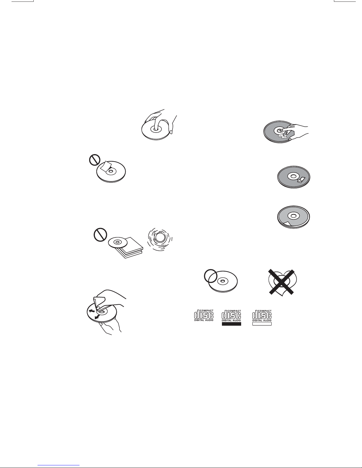
NOTES ON CDs
1.
A dirty or defective disc may cause sound
dropouts while playing. To enjoy optimum
sound, handle the disc as follows.
Handle the disc by its edge. To keep the
disc clean, do not touch the surface (P.1).
P. 1
Do not stick paper ortape on thedisc (P.2).
2.
P. 2
Do not expose the discs to direct sunlight or
3.
heat sources such as hot air-ducts, or leave
them in a car parked in direct sunlight where
there can be a considerable rise in
temperature inside the car (P.3).
P. 3
4.
Before playing, clean the discs with an
optional cleaning cloth. Wipe each disc from
the center out (P.4).
NOTES ON DISCS
If you use the discs explained below, the sticky
residue can cause the CD to stop spinning and
may cause malfunction or ruin your discs.
Do not use second-hand or rental CDs that
have a sticky residue on the surface (for
example, from peeled-off stickers or from ink, or
glue leaking from under the stickers).
There are paste residue.
Ink is sticky (P.5).
*******
*******
P. 5
Do not useCDs withold labelsthat are beginning
to peel off.
Stickers that are beginning
to peel away, leaving a
sticky residue (P.6).
P. 6
Do not use your CDs with labels or stickers
attached.
Labels are attached (P.7).
P. 7
Do Not Use Special Shape CDs
Be sure to use round shape CDs only for this
unit and do not use any special shape CDs.
Use of special shape CDs may cause the unit
to malfunction.(P.8).
****
*******
*******
**************
*******
*******
*******
*******
*******
*******
*******
*******
P. 4
Do not use solvents such as benzine,
5.
thinner,commercially available cleaners, or
antistatic spray intended for analog discs.
P. 8
Be sure to use CDs with disc mark
RECORDABLE
REWRITABLE
Only for this unit.
CD-Rs and CD-RWs which have not undergone
finalization processing cannot be played. (For
more information on finalization processing,
refer to the manual for your CD-R/CD-RW
writing software or CD-R/CD-RW recorder.)
Additionally, depending on the recording status,
it may prove impossible to play certain CDs
record on CD-R or CD-RW.
3
Page 5
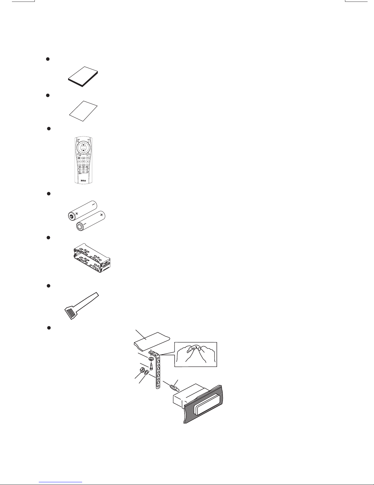
3. ACCESSORY INCLUDED
When first unpacking your new head unit, please check first that the package contains all of the
items below. If something is missing, contact the store where you purchased the player.
Owner s Manual
Owner s
manual
Warranty Card
Warranty
Card
Remote control
2 x AAA Type Battery
Half Sheeve
Insert Key
1. Dashboard
2. Nut (5mm)
3. Spring washer
4. Screw (4X12mm)
5. Screw
6. Support Strap
7. Plain washer
1
6
7
4
2
5
3
4
Page 6

4. INSTALLATION
Before finally installing the unit, connect the wiring temporarily and make sure it is all connected up
properly and the unit and system work properly.
Use only the parts included with the unit to ensure proper installation. The use of unauthorized
parts can cause malfunctions.
Consult with your nearest dealer if installation requires the drilling of holes or other modifications of
the vehicle.
Install the unit where it does not get in the driver's way and cannot injure the passenger if there is a
sudden stop, like an emergency stop.
If installation angle exceeds 30° from horizontal, the unit might not give its optimum performance.
30°
Avoid installing the unit where it wouldbe subject to high temperature, such as from directsunlight, or
from hot air,from heater,or where itwould be subjectto dust dirtor excessive vibration.
Be sure to remove thefront panel beforeinstalling the unit.
DIN FRONT/REAR-MOUNT
This unit canbe propertyinstalled eitherfrom “Front” (conventional DINFront-mount) or “Rear”(DIN
Rear-mount installation, utilizing threaded screw holes at the sides of the unit chassis). For
details, refer tothe followingillustrated installationmethods Aand B.
DIN FRONT-MOUNT (Method A)
Installation the unit
1
2
182
53
3
1. Dashboard
2. Holder
After inserting the half sleeve into the
dashboard, select the appropriate tab according
to the thickness of the dashboard material and
bend them inwards to secure the holder in
place.
3. Screw
1
6
7
4
2
5
3
1. Dashboard
2. Nut (5mm)
3. Spring washer
4. Screw (4x12mm)
5. Screw
6. Support Strap
Be sure to use the support strap to secure the
back of the unit in place. The strap can be bent
by hand to the desired angle.
7. Plain washer
5
Page 7
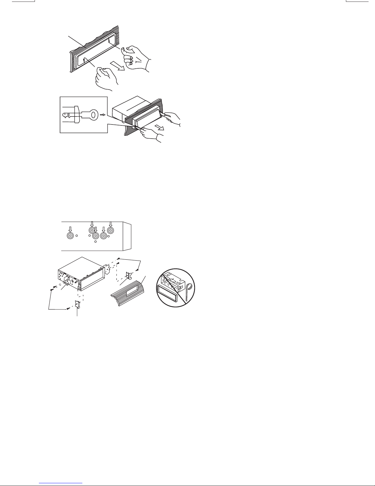
Removing the unit
a
a. Frame
b. Insert fingers into the groove in the front
of frame and pull out to remove the
frame. (When re-attaching the frame,
point the side with a groove down wards
b
c
Trim Plate Installation:
Push the trim plate against the chassis until it is fitted.
You must do this before you install the front panel, otherwise it can't be attached.
DIN REAR-MOUNT (METHOD B)
Installation using the screw holeson the sidesof the unit.
Fasteningthe unitto the factoryradio mounting bracket.
and attach it.)
c. Insert the levers supplied with the unit
into the grooves at both sides of the unit
as shown in figure until they click. Pulling
the levers makes it possible to remove
the unit from the dashboard.
1. Select a position where the screw holes
of the bracket and the screw holes of the
main unit become aligned (are fitted)
and tighten the screws at 2 places on
2
4
5
3
2
each side.
2. Screw
3. Factoryradio mounting bracket.
4. Dashboardor Console
5. Hook(Remove thispart)
Note: the mounting box, outer trim ring,
and half-sleeve are not used for method B
installation.
5
6
Page 8

5. DETACHABLE CONTROL PANEL (D.C.P.)
Removing The Detachable Control Panel (D.C.P.).
1. Turn the power off
2. Press the D.C.P. release button
3. Remove the D.C.P.
PANEL RELEASE
BUTTON
Attaching the DCP
1. Attach the panel at the right side first, with
2
A
B
point B on the main unit touching point A on
the D.C.P. (As shown on the digram).
2. Then press the leftside of D.C.P. onto the main
unit until a “click” soundis heard.
CAUTION
DO NOT insertthe D.C.P fromthe left side. Doing so may damage it.
The D.C.P can easilybe damagedby shocks.After removing it,place it ina protective case andbe careful notto drop
it or subjectit tostrong shocks.
When the release button is pressed and the D.C.P is unlocked, the car's vibrations may cause it to fall. To prevent
damage to theD.C.P, always store it in a protective case after detaching it.
The rear connector that connects the main unit and the D.C.P is an extremely important part. Be careful not to
damage it bypressing onit with fingernails, pens,screwdrivers, etc.
Note:
If the D.C.P is dirty, wipe off the dirt with soft, dry
cloth only. And use a cotton swab soaked in
isopropyl alcohol to clean the socket on the back
Socket
of the D.C.P.
7
Page 9

6. WIRING DIAGRAM (20 PIN HARNESS PLUG)
FUSE
SICHERUNG
FUSIBLE
FUSíVEL
FUSIBLE
FUSIBILE
20-PIN AUDIO/POWERHARNESS (See Figure1)
20-PIN AUDIO/STROM- KABELGESCHIRR
PLAQUE 20 FICHES AUDIO/ALIMENTATION
CONECTOR DE 20 PINOS PARA AUDIO E ALIMENTACAO
CONECTOR DEAUDIO / POTENCIADE 20 PIN
CONNETTORE ISO( vedi figura1)
LINE OUT POSTERIORE---GRIGIO
RÜCKANSCHLUSS-AUS GRAU
SORTIE ARRIERE-GRIS
SALIDA DE LINEA TRASERA -GRIS
REAR LINE OUT---GREY
SAIDA TRASEIRA- CINZA
RCA-TO-RCA CABLES
(not supplied)
RCA-TO-RCA-KABEL
(nicht geliefert)
CABLES RCA-TO-RCA
(non fournis.)
CABOS RCA A RCA
(não fornecidos)
CABLES RCA A RCA
(no incluidos)
CAVO RCA A RCA
( non fornito)
AMP
Le fil de l'antenne de la puissance et l'éloignement mettent la conduite sous tension.
Ground verbindet sich mit Bodenendstation oder reinigt nichtgestrichenen Metallteil von Chassis
Le Ground se Connecte au terminal de la terre ou Lave la partie non peinte du métal du chssis
Ground Connect to ground terminal or Clean unpainted metal part of chassis
Terra-Conecte Ao Terminal Negativo Ou A Uma Superficie Metalica (sem Pintura) Do Chassi.
El Ground Conecta a terminal de tierra o Completamente despintó parte metálica de chasis
Il Ground si collega a terminale terrestre di parte di metallo non verniciare pulita di telaio
Treiben Sie Antennenleitung und entfernte Drehungsführung an.
Power antenna wire and remote turn on lead.
Impulse alambre de antena y turno remoto en liderazgo.
Il filodi potenza diantenna e ilremoto accendono comando.
Fio ParaAntena Eletrica.
WHITE
WEISS
BLANC
BRANCO
BLANCO
BIANCO
L-CH
R-CH
RED/ROT/ROUGE/VERMELHO/ROJO/ROSSO
BLUE/BLUE/BLUE/AZUL/AZUL/BLU
BLACK/BLACK/BLACK/PRETO/NEGRO/NERO
Memory/Battery
Connect to a constant 12 volt source. The radio will not work if this wire is not connected.
Geds/Batterie
Verbinden Siesich mit einer Konstanten 12Voltquelle. Das Radio wirdnicht funktionieren, wenn
diese Leitungnicht verbunden ist.
Mémoire/Pile
Connectez-vous àune source constantedu volt 12.La radio ne fonctionnerapas si cefil n'est pas
connecté.
Memória/Bateria
Conecte auma fonte constante de 12V. O radionao funcionara se este fionao estiver conectado.
Memoria/Batería
Conectea unorigen constantede 12volt. Laradio nofuncionará sieste alambreno estáconectado.
Memoria/ Batteria
Collegatevi auna 12 sorgentedi volt costante.La radio non lavoreràse questo filonon è collegato
YELLOW/YELLOW/YELLOW/AMARELO/AMARILLO/GIALLO
RED/RED/RED/VERMELHO/ROJO/ROSSO
Accessory/Ignition - Connect to a switched 12 volt source.
Zubehr/ Zündung - verbindet sich mit einer umgeschalteten 12 Voltquelle.
Accessoire/ Allumage - se Connecte à une source commutée du volt 12.
Acessorio /Ignicao - Conectea uma fontede 12V chaveada.
Accesorio/ Ignición - Conecta a un origen conmutado de 12 volt.
L'accessorio/ L'accensione - si Collega a una 12 sorgente di volt commutata.
ANTENNA CABLE INPUT
ANTENNENVERLÄ NGERUNGSKABEL
CÂBLE D'EXTENSION D' ANTENNE
ENTRADA PARA CABO DE ANTENA
CABLE DE ANTENA
CAVO ANTENNA ESTENDIBILE
LEFTFRONT
LINKEVORDERSEITE
FACEAVANT GAUCHE
FRENTEESQUERDO
PARTEfrontal IZQUIERDA
PARTEanteriore SINISTRA
LEFT REAR
LINKE RÜCKSEITE
ARRIERE GAUCHE
TRASEIRO ESQUERDO
PARTE POSTERIOR IZQUIERDA
RETRO SINISTRO
WHITE-BLACK/WEISS-SCHWARZ/ BIANCO-NERONOIR-BLANC/BRANCO-CINZA/BLANCO -NEGRO/
GREEN-BLACK/ /VERT-NOIR/VERDE-PRETO/VERDE-NEGRO/VERDE-NEROGRÜN-SCHWARZ
20-PIN AUDIO/POWER HARNESS
6 6
5 5
3 3
4 4
1 1
PIN
1
2
3
4
5
6
7
8
9
10
11
12
13
14
15
16
17
18
19
20
2 2
13 13
11 11
12 12
Figure 1
WIRE COLOR
GREY/BLACK
GREY
VIOLET
VIOLET/BLACK
GREEN
GREEN/BLACK
RED
BLACK
RED
WHITE
WHITE/BLACK
BLUE
YELLOW
BLACK
WHITE
7 7
9 9
8 8
14 14
15 15
10 10
16 16
20 20
18 18
17 17
19 19
Pin View
FUNCTION/LABEL
RIGHT FRONT SPEAKER (-)
RIGHT FRONT SPEAKER (+)
RIGHT REAR SPEAKER (+)
RIGHT REAR SPEAKER (-)
LEFT REAR SPEAKER (+)
LEFT REAR SPEAKER (-)
IGNITION(ACC)
REAR PRE-AMP LINE OUT COMMON
RIGHT REAR PRE-AMP LINE OUT
LEFT FRONT SPEAKER (+)
LEFT FRONT SPEAKER (-)
POWER ANTENNA
BATTERY(+)
CHASSIS GROUND
LEFT REAR PRE-AMP LINE OUT
20-PIN AUDIO/STROM-KABELGESCHIRR
653412
79810
KABELFARBE
PIN
1
GRAU/SCHWARZ
2
GRAU
3
VIOLETT
4
VIOLETT/SCHWARZ
5
GRÜN
6
GRÜN/SCHWARZ
7
8
ROT
9
SCHWARZ
10
ROT
11
WEISS
WEISS/SCHWARZ
12
13
14
BLAU
15
GELB
SCHWARZ
16
17
18
19
WEISS
20
141311 12 15 16
Figure 1
RECHTER VORDERLAUTSPRECHER (-)
RECHTER VORDERLAUTSPRECHER (+)
RECHTER RÜCKLAUTSPRECHER (+)
RECHTER RÜCKLAUTSPRECHER (-)
LINKER RÜCKLAUTSPRECHER (+)
LINKER RÜCKLAUTSPRECHER (-)
ZÜNDUNG (ACC)
RÜCK-PRE-AMP-ANSCHLUSS -AUS
RECHTER RÜCK-PRE-AMP-ANSCHLUSS-AUS
LINKER VORDERLAUTSPRECHER (+)
LINKER VORDERLAUTSPRECHER (-)
MOTORISIERTE ANTENNE
BATTERIE (+)
GEHÄUSEERDUNG
LINKER RÜCK-PRE-AMP-ANSCHLUSS
201817 19
Pin View
FUNKTION / ETIKETT
WHITE/WEISS/BLAC/BRANCO/BLANCO/BLANCO
GREEN/GRÜN/VERT/VERDE/VERDE/VERDE
PLAQUE 20 FICHES AUDIO/ALIMENTATION
Schéma 1
COULEUR DU CABLE
FICHE
1
GRIS/NOIR
2
GRIS
3
VIOLET
4
VIOLET / NOIR
5
VERT
6
VERT/NOIR
7
8
ROUGE
9
NOIR
10
ROUGE
11
BLANC
NOIR/BLANC
12
13
14
BLEU
15
JAUNE
NOIR
16
17
18
19
BLANC
20
Conector de 20 pinos para audio e alimentação
1
2
11
12
13
Vue des fiches
FONCTION / MARQUE
ENCEINTE AVANT DROIT (-)
ENCEINTE AVANT DROIT (+)
ENCEINTE ARRIERE DROIT (+)
ENCEINTE ARRIERE DROIT (-)
ENCEINTE ARRIERE GAUCHE (+)
ENCEINTE ARRIERE GAUCHE (-)
ALLUMAGE (ACC)
SORTIE COMMUNE ARRIERE PRE-AMP
SORTIE PRE-AMP ARRIERE DROITE
ENCEINTE AVANT GAUCHE (+)
ENCEINTE AVANT GAUCHE (-)
PUISSANCE ANTENNE
BATTERIE (+)
CHASSIS TERRE
SORTIE PRE-AMP ARRIERE GAUCHE
6
5
3
4
7
9
8
14
13
15
ALTO-FALANTE DIANTEIRO DIREITO (-)
ALTO-FALANTE DIANTEIRO DIREITO (+)
10
16
20
18
17
19
(-)
IGNIÇÃO (ACC)
SAÍDAPRE-AMP TRASEIRA(FIO COMUM)
SAÍDA PRE-AMPTRASEIRA DIREITA
ALTO-FALANTE DIANTEIRO ESQUERDO (+)
ALTO-FALANTE DIANTEIRO ESQUERDO (-)
ANTENA ELÉTRICA
MASSA (FIO TERRA)
SAÍDA PRE-AMP TRASEIRA ESQUERDA
8
GREY-BLACK/GRAU-SCHWARZ/GRIS-NOIR/CINZA-PRETO
/GRIS-NEGRO/GRIGIO-NERO
GREY/GRAU/GRIS/CINZA/GRIS/GRIGIO
VIOLET-BLACK/
VIOLETT-SCHWARZ/VIOLET-NOIR/VIOLETA-PRETO
/VIOLETA-NEGRO/
VIOLA-NERO
VIOLET/VIOLETT/VIOLET/VIOLETA/VIOLETA/VIOLA
CONECTORDEAUDIO/POTENCIA20PIN
3
4
1
2
14
13
11
12
Imagen 1
COLOR DE CABLE
PIN
1
2
3
4
5
6
7
8
9
10
11
12
13
14
15
16
17
18
19
20
GRIS/ NEGRO
GRIS
VIOLETA
VIOLETA / NEGRO
VERDE
VERDE / NEGRO
ROJO
NEGRO
ROJO
BLANCO
BLANCO / NEGRO
AZUL
AMARILLO
NEGRO
BLANCO
ALTAVOZFRONTAL DERECHO (-)
ALTAVOZFRONTAL DERECHO (+)
ALTAVOZTRASERO DERECHO (+)
ALTAVOZTRASERO DERECHO (-)
ALTAVOZTRASERO IZQUIERDO (+)
ALTAVOZTRASERO IZQUIERDO (-)
IGNICIÓN (ACC)
LINEA DE SALIDA PRE-AMP TRASERA
LINEA DE SALIDA PRE-AMP TRASERA DERECHA
ALTAVOZFRONTAL IZQUIERDO (+)
ALTAVOZFRONTAL IZQUIERDO (-)
ALIMENTACIÓN DE ANTENA
BATERÍA(+)
CHASIS DE TIERRA
LINEA DE SALIDA PRE-AMP TRASERA IZQUIERDA
IDENTIFICAZIONE PIN
3
4
1
2
14
13
11
12
FIGURA 1
COLORE CAVO
PIN
1
2
3
4
5
6
7
8
9
10
11
12
13
14
15
16
17
18
19
20
GRIGIO/NERO
GRIGIO
VIOLA
VIOLA/NERO
VERDE
VERDE/NERO
ROSSO
NERO
ROSSO
BIANCO
BIANCO/NERO
BLU
GIALLO
NERO
BIANCO
CASSAANTERIORE DESTRA (-)
CASSAANTERIORE DESTRA(+)
CASSA POSTER. DESTRA(+)
CASSA POSTER. DESTRA(-)
CASSA POSTER. SINISTRA (+)
CASSA POSTER. SINISTRA (-)
ACCENSIONE (TAKE OUT NIEZIONE)
MESSAA TERRA
AMPLIFICATORE CASSAPOST.
CASSAANTERIORE SINISTRA (+)
CASSAANTERIORE SINISTRA (-)
ANTENNA
BATTERIA(+)
MESSAA TERRA
AMPLIFICATORE CASSAPOST. SX
5
15
5
15
6
7
8
16
18
17
Vista de los Pin
FUNCI
6
7
8
16
18
17
VISUALE PIN
FUNZIONE
RIGHTFRONT
RICHTIGEVORDERSEITE
FACEAVANT DROITE
FRENTEJUSTO
PARTEFRONTALADECUADA
PARTEANTERIORE GIUSTA
RIGHTREAR
RICHTIGERÜCKSEITE
ARRIEREDROIT
DIREITOJUSTO
PARTEPOSTERIORADECUADA
RETROGIUSTO
9
10
20
19
9
10
20
19
DESTRA
Page 10

7. BASIC OPERATIONS
1) PANEL RELEASE BUTTON (REL)
Press this buttonto removethe controlpanel.
12) POWER ON/OFF BUTTON
Press this buttonto turnon or off the power.
5) DISPLAY BUTTON (DISP)
Press this button briefly, the LCD will display the clock for about 2 seconds, then return to previous
display mode.
Clock Adjustment
Under clock display mode, press DISP button until the LCD flashes, press Tuning Up Button to adjust
hour and Tuning Down Button to adjustminute.
16) SOURCE BUTTON (SOURCE)
Press this button to select Radio and CD modes.
The available selections depends on version:
Radio CD Player
Radio > CD
18) FRONT AUXILIARY INPUT JACK
AUX IN JACK IN PANEL
Connect the external signal to AUX in jack
located at the front of the panel , then press
SOURCE button to select Aux mode. Press
SOURCE button again to cancel Aux mode and
return to previous mode.
RESET BUTTON
1
Left Audio
2
Right Audio
3
Ground
3.5mm AudioIn Cable (notincluded)
The RESET button islocated onthe main unit(as shownon the diagram).To press itvertically with aballpoint pen
or metal object will activate it. Thereset button is to be activatedfor the following reasons:
Initial installation of the unitwhen all wiringis completed.
All the function buttons donot operate.
Error symbol on the display.
Note: If the unit cannotfunction normally after reseting please usea cotton swab soakedin isopropyl
,
alcohol to clean the socketon the backof the control panel.
9
Page 11

8. AUDIO OPERATIONS
10) VOLUME KNOB
Turn thisknob to adjustdesired volume level.
4) AUDIO BUTTON
Press this button to selectdesired audio function.
ORDER OF FUNCTION:
VOLUME(VOL) -> BASS(BAS) -> TREBLE(TRE) ->BALANCE(BAL) ->FADER(FAD)
While the selected function is displayed, turn Volume Knob to adjust the level within 5 seconds,
otherwise the unit will returnto volume adjustmentmode.
BEEPS 2ND,BEEP ALL ,BEEP OFF
Press and hold SELECT button to determine how the beep sound is generated when the keys are
pressed,using V-UP/V-DN to select the desires settings:
BEEP 2ND Beeps only when the second function of the dual function button is selected (long press).
BEEP ALL Beeps when any buttons is pressed.
BEEP OFF To disable the beep option.
2) MUTE BUTTON (MUTE)
Press this button to mutethe sound. Pressit again to resumelistening.
17) PRESET EQUALIZER BUTTON (EQ)
Press this button to togglethe following EQsettings:
FLAT->CLASSICS->POP M->ROCK M->DSP OFF
At DSP OFF mode, EQwill be controlledby Bass/Treblesetting.
13) BAND/LOUDNESS BUTTON (BAND/LOUD)
Press the Band/Loudness Button for couple of seconds to switch the loudness on or off. When Loudness
is on, display will show 'Loud On' for a few seconds.
10
Page 12

9. RADIO OPERATIONS
11) AUTO MEMORY STORE/PRESET SCAN BUTTON (AS/PS)
1. PRESET SCAN: Press AS/PS button briefly to enter Preset Scan mode, it will scan all the preset
stations in the memories, you can hear that it will stay on each station for about 5 seconds.
2. AUTO MEMORY STORE: Press AS/PS button for couple of seconds to enter Auto Store mode,
this feature will automatically scan the current band and enter up to 6 strongest stations into the
6 preset memories. To stop Auto Store & Scan, press the AS/PS button again.
7) STATION PRESET BUTTONS (M1-M6)
1. Press these buttons briefly to recall the stored stations in the selected band.
2. Presetting stations manually, Press the BAND button to select the band for the stations to be
preset. Use Tuning Up/Down to tune in the stations to be preset. Press the Preset button at
which you want to store the station for at least 2 second. The preset number will appear on the
display accompanied by a beep, this indicates that the station has been stored into memory.
13) BAND/LOUDNESS BUTTON (BAND/LOUD)
This a dual function button. Press this button shortly to change between BAND FM1, FM2, FM3 or
AM bands. Press this button for couple of seconds to turn Loudness function on or off.
DUAL FREQUENCY SWITCH
Unit is defaulted in U.S.A frequency, if EURO frequency is required, a sharp pen is needed to
switch the button on the left side of the chassis to EURO frequency.
EU
US
14) TUNING / SEEK UP AND TUNING / SEEK DOWN BUTTONS
1. Press these buttons briefly, and the unit will operate in AUTO SEARCH tuning mode, the radio
will tune up or down to the next station and remain on that station.
2. Press these buttons for more than 2 seconds, operate as MANUAL SEARCH buttons, under this
mode the tuning frequency will advance up or down rapidly when the button is pressed. If the
buttons are not pressed within 3 seconds, they will return to auto search mode.
8) MONO STEREO BUTTON (MO/ST)
When you receive a station,“ST” on the display will be on. Press this button to enter Mono mode.
9) SCAN BUTTON(SCAN)
Press this button, the radio will tune up to search stations, the available stations will blink and stay
on the display for a few seconds.
6) LOCAL/DISTANT BUTTON (LOC)
During station tuning, this button allows you prior to access strong local station only (Local
mode), or to access a wider range of using distant mode (DX). When powered on, DX mode will
be defaulted automatically; Press LOC button briefly to select Local mode and “LOCAL” symbol
on the LCD will light up for a few seconds.
11
Page 13

10. CD OPERATIONS
M1) PAUSE BUTTON (PAUSE)
Press this button to pauseCD play,press againto release pause.
M2) SCAN BUTTON (SCAN)
Press this button, the first 10 seconds of each track will be played sequentially until this button
is pressed again, then normalplay will resumeat the current track.
M3) REPEAT BUTTON (REPEAT)
Press this button, the currenttrack will beplayed repeatedly until thisbutton is pressedagain.
M4) SHUFFLE BUTTON (SHUFFLE)
Press this button to playall tracks onCD in random. Pressagain to deactivateit.
14) TRACK UP AND TRACK DOWN BUTTON
Press the Track Up Button to skip to the next track or previous track. Press the Track Down
button during playwill returnto thebeginning ofthe currenttrack, pressit onemore timeto skip
to previous skip. Press and hold Track Up/Down Button to fast forward or fast reverse. CD
player starts playing when yourelease the button.
EJECT BUTTON
Press this button to eject the CD from the unit. The receiver will switch to radio mode
automatically.
EJECT BUTTON
12
Page 14
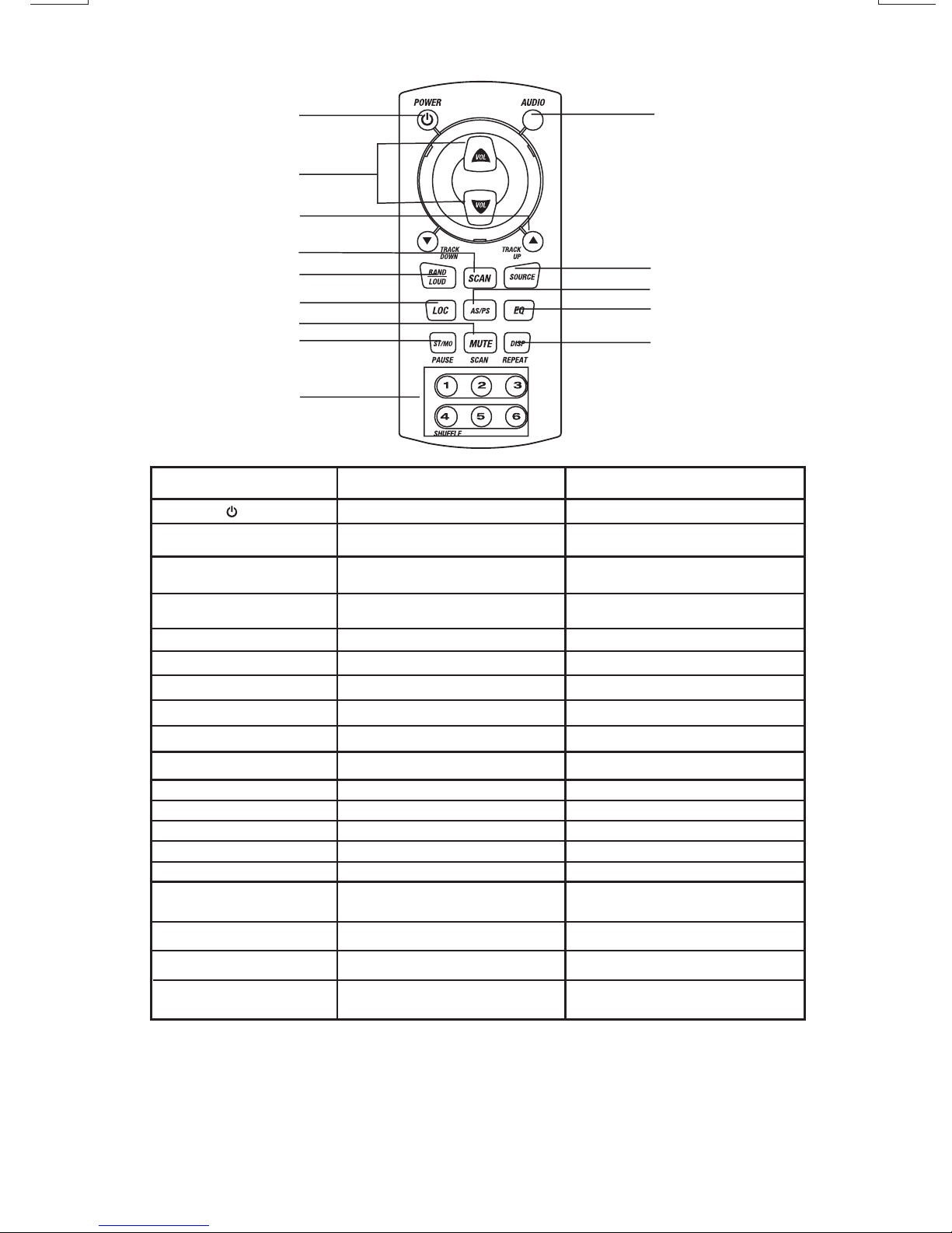
11. REMOTE CONTROL
10
OPERATIONS:
Key
1. Power
2. Audio
3. Volume Up/Down
4. Tuning Up/Down
()
1
3
4
5
6
7
8
9
Radio Mode
Power On/Off
Select Vol, Bas,
Tre,Fad, Bal
Adjust Vol,Bas,
Tre,Fad,Bal
Tuning/SeekUp/Down
2
11
12
13
14
CD Player Mode
Power On/Off
Select Vol, Bas,
Tre,Fad, Bal
Adjust Vol,Bas,
Tre,Fad,Bal
TrackUp/Down
5. Scan (SCN)
6. Band (BND)
7. Loc
8. Mute
9. Mono/ST (MO)
10. Numeric Key(1)
(2)
(3)
(4)
(5)
(6)
11. Mode (MOD)
12. AMS
13. PEQ
14. DISP
Station Scan
Band/Loudness
Local/DX
Mute
FM Mono/Stereo
Preset station 1
Preset station 2
Preset station 3
Preset station 4
Preset station 5
Preset station 6
Change to CDMode
Auto Store/Preset Scan
Preset EQ
Display Clock
Note: Please use the 2 x AAA type battery.
No Function
Loudness
No Function
Mute
No Function
Pause
CD Scan
Repeat
Shuffle
No Function
No Function
Change to RadioMode
No Function
Preset EQ
Display Clock, Track,
Play Time
13
Page 15

12. SPECIFICATIONS
CD PLAYER
System
Usable disc
Sampling frequency
No ofquantization bits
Frequency
Number ofchannels
S/N Ratio
RADIO SECTION
FM
Frequency Range
Intermediate Frequency
Usable Sensitivity
Stereo Separation
S/N Ratio
AM/MW
Frequency Range
Intermediate Frequency
Usable Sensitivity
S/N Ratio
GENERAL
Power Supply
Polarity
Speaker impedance
Power Output
REMARK :
Specifications subjectto changewithout notice.
CD PLAYER
System
Abspielbare Discs
Sampling-Frequenz
Anzahl Quantisierungsbits
Frequenz
Anzahl Kanäle
Signalrauschabstand
RADIOTEIL
FM
Frequenzbereich
Zwischenfrequenz
Nutzbare Empfindlichkeit
Stereotrennung
Signalrauschabstand
AM/MW
Frequenzbereich
Zwischenfrequenz
Nutzbare Empfindlichkeit
Signalrauschabstand
ALLGEMEINES
Stromversorgung
Polarität
Lautsprecherimpedanz
Ausgangsleistung
ANMERKUNG:
Technische Änderungen ohneMeldepflicht vorbehalten.
Compact discaudio system
Compact disc
44.1KHz
1bit
5-20,000Hz
2 stereo
70dB
87.5-107.9MHz U.S.
87.5-108MHz EURO
10.7 MHz
Better than15dB atS/N 30 dB
25 dBat 1KHz
50 dB
530-1710KHz U.S.
522-1620KHz EURO
450KHz
Better than45dB
40 dB
DC 11-14V
Negative Ground
4 ohms
4x 50Watts
Compact DiscAudio System
Compact Disc
44,1 kHz
1 bit
5-20.000Hz
2 Stereo
70 dB
87.5-107.9MHz U.S.
87.5-108MHz EURO
10.7 MHz
Besser als15 dBbei einem
Signalrauschabstand von30 dB
25 dBbei 1kHz
50 dB
530-1710KHz U.S.
522-1620KHz EURO
450KHz
Besser als45 dB
40 dB
DC 11-14 V
Erde negativ
4Ohm
50 Wx 4
CD Player
Sistema:
Tipo de disco:
Frequência de Amostragem:
Conversor D/A:
Resposta de frequencia
Número de canais:
Relação sinal/ruído:
Rádio FM
Faixa de Frequencia:
Frequência Intermediária:
Sensibilidade útil:
Separação estéreo
Relação Sinal/Ruído
AM/MW
Faixa defrequencia:
Frequencia intermediária:
Sensibilidade útil:
Relação Sinal/Ruído:
Geral:
Alimentação:
Polaridade:
Impedancia alto-falantes:
Potência de saída:
Nota:
As especificações estão sujeitas a alterações sem prévio aviso.
CD PLAYER
Sistema:
Disco:
Frecuencia Muestreo:
Cuantificación:
Frecuencia:
Número decanales:
Relación señal/RuidoS/N Ratio
RADIO SECCIÓN
FM
Rango Frecuencia:
Frecuencia Intermedia:
Sensibilidad Útil:
Separación estereo:
S/N Ratio:
AM/MW
Rango Frecuencia:
Frecuencia Intermedia:
Sensibilidad útil:
S/N Ratio:
GENERAL
Alimentación:
Polaridad:
Impedancia altavoces:
Potencia de salida:
Nota:
Debido alrápido avancetecnológico, estasespecificaciones están
sujetas acambios sinprevio aviso.
Sistema áudioCD
CD
44.1KHz
1bit
5-20,000Hz
2 estéreo
70dB
87.5-107.9MHz U.S.
87.5-108MHz EURO
10.7 MHZ
melhor que15dB aS/N 30dB
25 dBat 1KHz
50 dB
530-1710KHz U.S.
522-1620KHz EURO
450KHz
Melhor doque 45dB
40dB
DC 11-14V
Terra negativo
4ohms
50wx4
Compact discaudio system.
Compact Disc.
44.1KHz.
1bit.
5-20,000Hz.
2 estereo.
70dB
87.5-107.9MHz U.S.
87.5-108MHz EURO
10.7Mhz.
Mejor que15dB aS/N 30dB.
25dB a1Khz.
50dB.
530-1710KHz U.S.
522-1620KHz EURO
450KHz.
Mejor que45dB.
40dB.
DC 11-14V.
Negativo a masa.
4 Ohms.
4x50W.
LECTEUR CD
Système
Disques utilisables
Fréquence échantillonnage
Nbre dequantisation bits
Fréquence
Nombre decanaux
Ratio S/B
SECTION RADIO
FM
Gamme defréquences
Fréquence intermédiaire
Sensibilité utilisable
Séparation stéréo
Ratio S/B
AM/MW
Plage defréquences
Fréquence intermédiaire
Sensibilité utilisable
Rapport Signal/Bruit
GENERAL
Alimentation
Polarité
Résistance desenceintes
Puissance desortie
REMARQUE :
Les spécifications sont susceptibles d'être modifiées sans
préavis.
Compact discaudio system
Compact disc
44.1KHz
1bit
5-20,000Hz
2 stéréo
70dB
87.5-107.9MHz U.S.
87.5-108MHz EURO
10.7 MHz
Plus de 15dB àS/B 30dB
25 dBà 1KHz
50 dB
530-1710KHz U.S.
522-1620KHz EURO
450KHz
Supérieure à45 dB
40 dB
11 -14VDC
Masse /négative
4 ohms
50W x4
LETTORE CD
Sistema
Tipo di disco
Frequenza di campionatura
N° quantizzazioniBit
Frequenza
Numero diCanali
Rapporto S/N
SEZIONE RADIO
FM
Raggio diFrequenza
Frequenza intermedia
Sensibilità
Separazione Stereo
Rapporto S/N
AM/MW
Raggio diFrequenza
Frequenza intermedia
Sensibilità
Rapporto S/N
GENERALE
Alimentazione
Polarità
Impedenza altoparlanti
Potenza d'uscita
Le specifichesono soggettea cambiamentisenza
alcun preavviso.
14
Sistema di Audio CD
CD
44.1KHz
1 bit
5-20,000 Hz
2 stereo
70db
87.5-107.9MHz U.S.
87.5-108MHz EURO
10.7 Mhz
migliore di15dB aS/N 30 dB
25dB a1KHz
50dB
530-1710KHz U.S.
522-1620KHz EURO
450Khz
migliore di45dB
40dB
Dc11 14V
Terra negativo
4 ohms
4x 50Watts
Page 16

13. TROUBLE SHOOTING
Before going through the check list, check wiring connection. If any of the problems persist after check
list has been made, consultyour nearest servicedealer.
Symptom
No power
Disc cannot be loaded
or ejected
No sound
The operation keys do
not work
Cause
The car ignition is not on.
The fuse is blown.
Presence of CD disc inside
the player.
Inserting the disc in reverse
direction.
Compact disc is extremely
dirty or defective disc.
Temperature inside the car is
too high.
Condensation.
Volume is in minimum.
Wiring is not properly
connected.
The built-in microcomputer is
not operating properly due to
noise.
Solution
If the power supply is properly connected
to the car accessory terminal, switch the
ignition key to “ACC”
Replace the fuse.
Remove the disc in the player, then put a
new one.
Insert the compact disc with the label
facing upward.
Clean the disc or try to play a new one.
Cool off or until the ambient temperature
returns to normal.
Leave the player off for an hour or so,
then try again.
Adjust volume to a desired level.
Check wiring connection.
Press the RESET button.
Front panel is not properly fixed into its
place
Sound skips.
The radio does not
work.
The radio station
automatic selection
does not work.
ERROR 1
ERROR 2
If at any time in the future you should need to dispose of this product please note
that Waste electrical products should not be disposed of with household waste.
Please recycle where facilities exist. Check with your Local Authority or retailer for
recycling advice.(Waste Electrical and Electronic Equipment Directive)
The installation angle is
more than 30 degrees.
The disc is extremely dirty or a
defective disc.
The antenna cable is not
connected.
The signals are too weak.
Mechanism Error
Servo Error
Adjust the installation angle to less than
30 degrees.
Clean the compact disc or try to play a
new one.
Insert the antenna cable firmly.
Select a station manually.
Press the reset button if the error code
does not disappear, consult your nearest
service dealer.
Press the reset button if the error code
does not disappear, consult your nearest
service dealer.
15
Page 17

10 R - 02 1397
4
 Loading...