

Page 1
Page 2
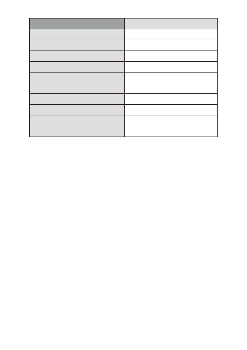
MR652C MR752C
Tweet er Type
Max Powe r (wa tts)
Ef ficiency (1W/1M)
Frequency Res pon se
Min. Mounting Dept h Allowing
Clearance(mm/i n)
Impedance
Sealed Enclosure Vo lum e (cu.f t)
Porte d Enclosure Volume (c u.f t)
Porte d diameter (mm/ in)
Port le ngt h (mm/in)
1” PEI Dome
350
90
40-20kHz
62mm / 2 7/16”
4 ohms
0.43 0.71
0.9
50mm(2”)
25mm(1”)
1” PEI Dome
400
92
60-20kHz
70mm / 2 3/4 ”
4 ohms
1.25
60mm(2-3/8” )
30mm(1-3/16”)
Calculating Required Enclosure Volume
Thes e loudspeaker s will perform best i f they are instal led in a sealed or a
port ed enclosure wi th the appropriat e interior volu me. Please refe r to the
tabl es for the suggested volume for your s peaker and appl ication.
Thes e volumes are provided in the table ab ove are in cubic fe et. In order
to des ign your enclos ure, you will first n eed to convert th is data to cubic
inch es. To con vert cubic feet to cubic inches, sim ply multiply by 1 728:
Mode l Sealed volume Por ted volume
MR65 2C 743 cu in. 1227 cu in.
MR75 2C 1572 cu in. 2160 cu in .
Calc ulating Enclo sure Dimensions
Calc ulating the exterior cabinet dim ensions requi res that you firs t
esti mate height and width of the enclosu re based on the ava ilable space
in you r boat. You then work w ith this estimate t o determine the d epth of
the ca binet.
For ex ample:
1. You wan t an MR652C seale d enclosure with exterior dimens ions of
8"W x 10 " H.
2. Sub tract the cabinet material thick ness (3/4" MDF x 2) f rom the
PAGE 1
Page 3

exte rior W X H = 6.5" x 8.5" (this yields the inte rior W x H).
3. Mul tiply (interior width) x (interi or height): 6.5 " x 8.5" = 55.25".
4. Div ide the require d interior volume f rom the table by th is number: 743
÷ 55.2 5 = 13.45". This reveals the interior dept h required.
5. Add 1- 1/2" to this dimension to calculat e exterior dept h: 13.45" + 1.5" =
12.9 5".
In the a bove example we showed that one poss ible sealed cab inet size
for MR 652C is approx. 8" x 10" x 13". We can see that if a 13" d eep
encl osure cannot be a ccommodated in yo ur boat, it will be n ecessary to
incr ease the height , width or both to come o ut with an enclos ure of
acce ptable size with the appropriate i nterior volum e.
Impo rtant considerations when buil ding an enclosu re
Be sur e that the cabinet is air-tight. Joi nts should be glu ed and caulked
on the i nterior of the joints.
For ma rine cabinets which may be exposed t o moisture, be su re to use an
appr opriate marin e varnish to seal the s urface of the MDF w ell.
Wiring
PAGE 2
Page 4

SPEAKER DIMENSIONS
6.5 -INC H
7.5 -INC H
PAGE 3
Page 5

6.5-INCH FULL RANGE
MARINE SPEAKER
6.5”(165mm) CUSTOM TOO LED HIGH EFFICIENCY
POLY INJECTION CONE
BUTYL RUBBER SURROUND
1-1/2”(38mm) ALUMINUM VOICE COIL
350 watts peak / 175 watts RMS
FREQUENCY RESPONSE:60Hz-20KHz
SENSITIVITY:90dB( 1WATT/1METER)
IMPEDANCE:4 OHMS
MOUNTING DEPTH:2-7/16”(62mm)
MOUNTING DIAMETER:6 2/16”(156mm)
7.5-INCH FULL RANGE
MARINE SPEAKER
PAGE 4
7.5”(190mm) CUSTOM TOO LED HIGH EFFICIENCY
POLY INJECTION CONE
BUTYL RUBBER SURROUND
1-1/2”(38mm) ALUMINU M VOICE COIL
400 watts peak / 200 watts RMS
FREQUENCY RESPONSE:40Hz-20KHz
SENSITIVITY:92dB(1WATT/1METER)
IMPEDANCE:4 OHMS
MOUNTING DEPTH:2-3/4”(70mm)
MOUNTING DIAMETER:6 11/16”(169.5mm)
Page 6

 Loading...