

Page 1
Thank you, and congratulations on your choice of BOSS WP-20G GK Effect.
Before using this unit, carefully read the sections entitled: “USING THE UNIT SAFELY”
and “IMPORTANT NOTES” (p. 18; p. 21).
These sections provide important information concerning the proper operation of the unit.
Additionally, in order to feel assured that you have gained a good grasp of every feature
provided by your new unit, Owner’s manual should be read in its entirety. The manual should
be saved and kept on hand as a convenient reference.
Main Features
●
New kind of effect for use with GK pickups and GK-Ready guitars.
●
Amazing new synth-like sounds not possible with conventional effects..
●
Built-in chorus and delay for even more sound variety.
●
Send and return for direct guitar signal.
●
The controls and pedals provide simple and intuitive operation.
●
Can run on battery power (six AA type).
Copyright © 2001 BOSS CORPORATION
All rights reserved. No part of this publication may
be reproduced in any form without the written
permission of BOSS CORPORATION.
Page 2
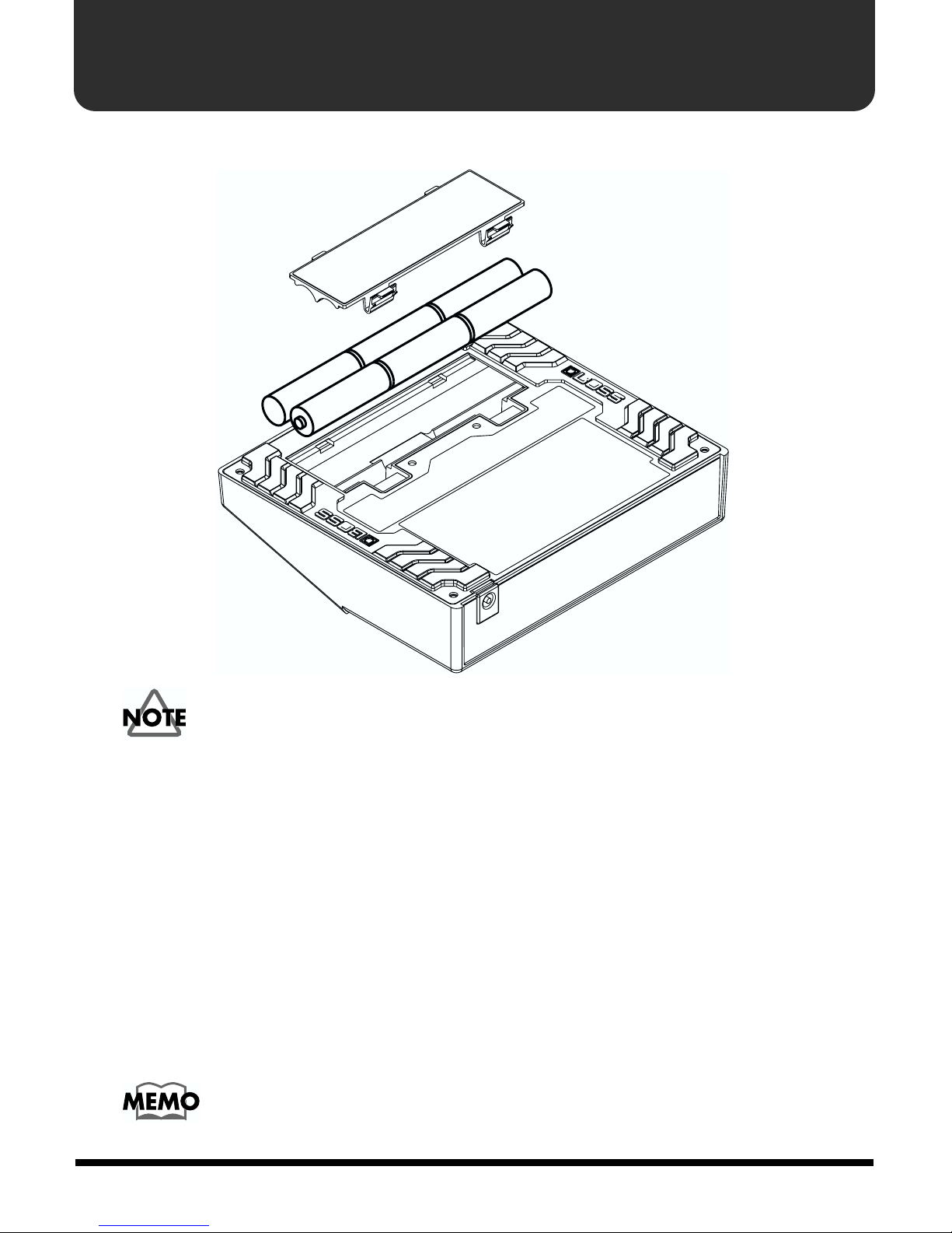
Installing Batteries
Insert the included batteries as shown in figure, being careful to orient the batteries correctly.
fig.02
2
• When turning the unit upside-down, get a bunch of newspapers or magazines,
and place them under the four corners or at both ends to prevent damage to
controls. Also, you should try to orient the unit so no controls get damaged.
• When turning the unit upside-down, handle with care to avoid dropping it, or
allowing it to fall or tip over.
• Make sure the “+” and “-” ends of the batteries are oriented correctly.
• When the batteries run down, the POWER indicator gets dim. If this happens,
replace with new batteries.
• When replacing the batteries, use six AA type.
• Do not mix fresh batteries with used ones, or mix batteries of different types.
Doing so can result in fluid leakage.
• Battery life can vary depending on battery type.
Continuous usage time under battery power is about 6 hours with alkaline
batteries and about 2 hours with carbon batteries. (This may vary according
to usage conditions.)
Page 3
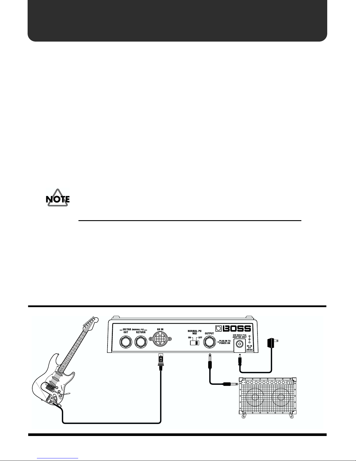
Making the Connections
About the GK-2A
To use the WP-20G with a guitar equipped with the GK-2A (or other GKcompatible guitar), you will need an optional GK cable.
Refer to the GK-2A Owner’s Manual for instructions on installing the GK-2A.
S1/S2 Switch
The GK-2A’s S1/S2 switches correspond to this unit’s MASTER On/Off pedal
and Effects On/Off pedal, respectively.
Selection Switch
Set to the “MIX” position.
Note that this unit processes tones using the instrument’s divided pickup
signal (signal output when SYNTH is selected).
No sound is produced when the following settings are combined.
GK-2A This unit’s settings
SYNTH MASTER: OFF
GUITAR MASTER: ON + NORMAL PU MIX: OFF (rear panel)
SYNTH VOL Knob
Controls the volume when MASTER ON is selected.
Connecting
fig.03
AC Adaptor
PSA-series
(sold separately)
Guitar with GK-2A
or other
GK-compatible guitar
Guitar Amp
3
Page 4

Making the Connections
• To get the best performance from the instrument, set your amp to “Clean” (no
distortion).
• When connecting the instrument to a guitar amp, make the necessary adjustments
to get the most suitable tone. When recording direct, use this with a COSM amp
(GT-3, GP-20 etc.).
• When connecting a GK cable, insert the cable completely until the connector is
securely locked. When disconnecting, press the connector’s lock while you detach
the cable.
* Always turn the amp volume down completely before connecting and disconnecting cords.
* To prevent malfunction and/or damage to speakers or other devices, always turn down the
volume, and turn off the power on all devices before making any connections.
* If there are batteries in the unit while an AC adaptor is being used, normal operation will
continue should the line voltage be interrupted (power blackout or power cord disconnection).
Turning On the Power
Be sure to observe the following order when connecting devices and switching on the
power to your equipment. By turning on devices in the wrong order, you risk causing
malfunction and/or damage to speakers and other devices.
Connect the GK-2A ➝ (Connect the AC Adaptor) ➝ Connect the Amp ➝ Turn On Amp Power
* When the unit is running on battery power, the power comes on when you insert the connector
plug into the OUTPUT jack.
* Always make sure to have the volume level turned down before switching on power. Even with
the volume all the way down, you may still hear some sound when the power is switched on,
but this is normal, and does not indicate a malfunction.
* When operating on battery power only, the unit’s indicator will become dim when battery
power gets too low. Replace the battery as soon as possible.
4
Page 5

Operating Instructions
Using the Pedals
“MASTER: ON” and “EFFECTS: OFF” are selected when the power is
turned on.
fig.04
When at “ON” When at “OFF”
Illuminated
Master is toggled on and off by stepping
on the MASTER On/Off pedal.
When switched on, the tone selected
with the TYPE knob is output.
When off, the output from the divided
pickup is muted, and the sounds from
the normal pickup (or the sounds input
to GUITAR RETURN) are output
without change.
➝
Extinguished
When at “ON” When at “OFF”
Illuminated
The effect (DELAY, CHORUS) can be
toggled on and off by stepping on
the Effects On/Off pedal.
DELAY and CHORUS are
not applied to the Normal
Pickup output.
➝➝➝
Extinguished
5
Page 6
Operating Instructions
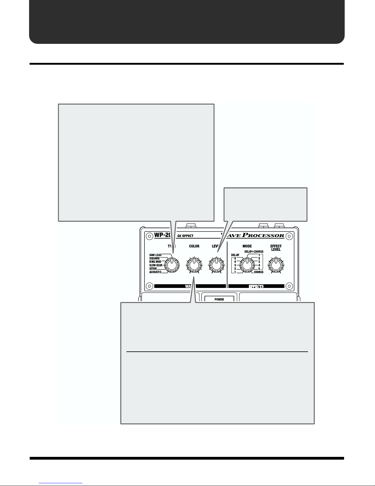
Panel Operations
In order to follow along with the instructions given here, you should start out by having
Master switched ON (press the MASTER On/Off pedal and confirm that the MASTER ON/
OFF indicator has lighted). Also, press the Effects On/Off pedal to switch OFF effects
(EFFECTS ON/OFF indicator extinguished).
fig.05
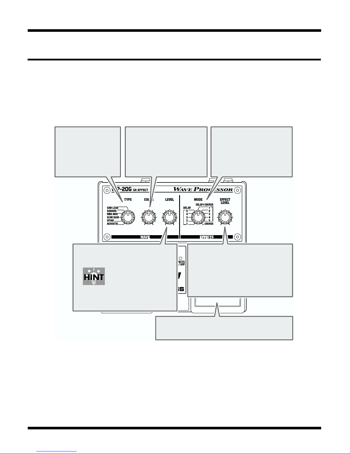
Select a tone.
1.
You can select
six different
wave types with
the TYPE knob.
3.
Adjust the tone with
2.
the COLOR knob.
This knob adjusts the tone.
The way in which it works
will vary depending on the
effect type selected.
Turn the LEVEL knob to
adjust the volume.
Adjust this while
switching the MASTER
On/Off pedal so that the
volume is roughly the
same whether Master is
on or off.
Turn the MODE knob
5.
to select one of eleven
effect modes.
This switches the
DELAY and CHORUS
settings.
Turn the EFFECT LEVEL knob to
6.
adjust the volume of the effect.
If raising the effect level
increases the overall volume
too much, try reducing the
volume with the LEVEL knob.
6
Press the Effects On/Off pedal to switch the
4.
effects on (EFFECTS ON/OFF indicator is lit).
Page 7
Part Names and Functions
Front Panel
WAVE
fig.06
TYPE Knob
Select the tone.
SAW LEAD: Analog synth-type sound that is
perfect for lead guitar.
SQUARE: Analog synth-type sound perfect for
backing.
RING MOD:
SLOW GEAR:
SITAR: Sitar sound.
ACOUSTIC: Acoustic guitar sound.
Metallic, bell-like sound.
Sound that is effective for volume-
control performance techniques.
LEVEL Knob
Adjusts the volume.
COLOR Knob
These adjust the tone. Each TYPE works differently.
The following describes the basic function of each type.
TYPE Function
SAW LEAD: Clockwise rotation produces a brighter sound.
SQUARE: Clockwise rotation produces a brighter sound.
RING MOD:
SLOW GEAR:
SITAR:
ACOUSTIC:
Clockwise rotation increases the modulation frequency.
Clockwise rotation slows the attack.
Clockwise rotation increases the resonance effect.
Clockwise rotation changes the sound from a
highly resonant sound to a bright and lively sound.
7
Page 8
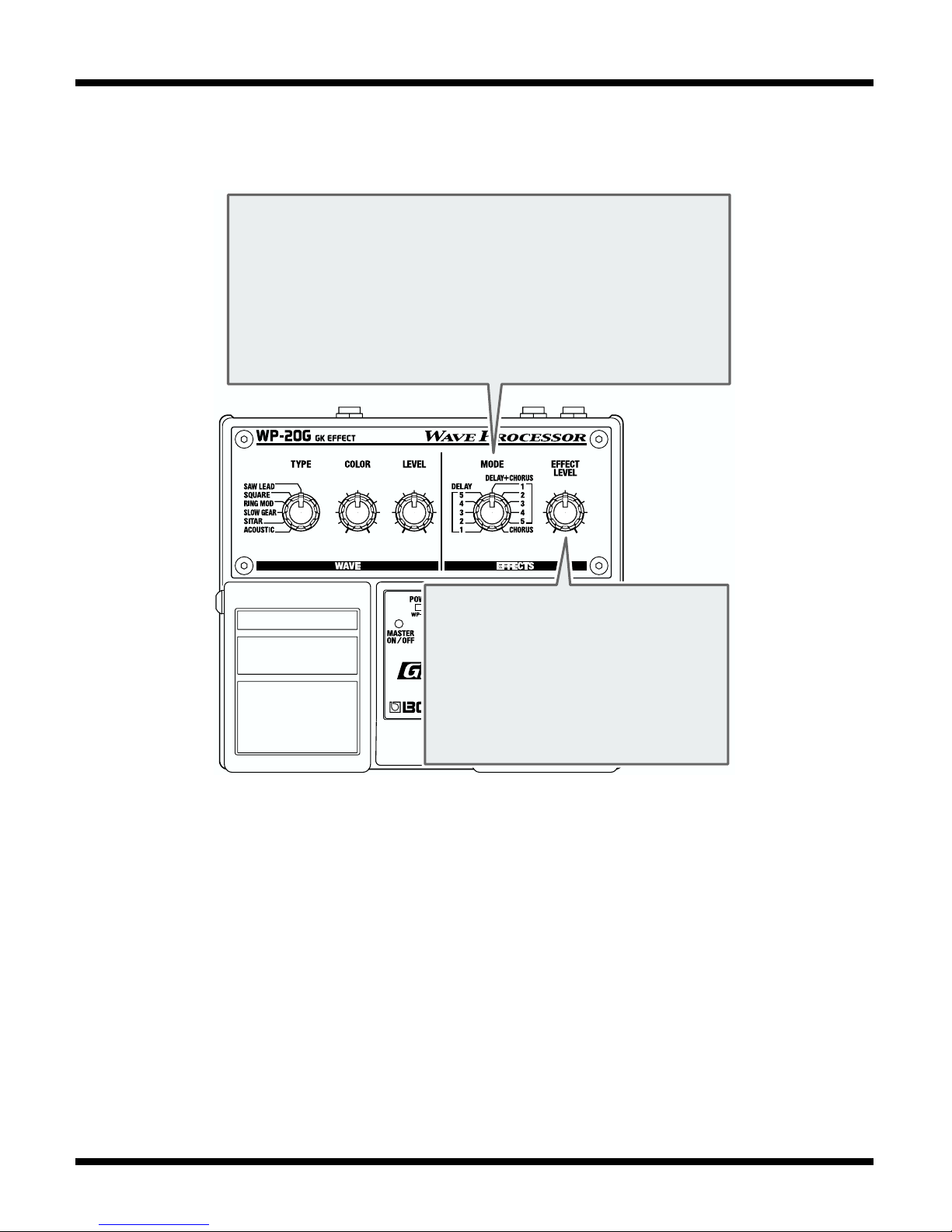
Part Names and Functions
EFFECTS
fig.07
MODE Knob
Used to make settings for the Effect mode.
DELAY 1: Sets the doubling (similar to twin guitars).
DELAY 2–5: Progressively longer delay times.
DELAY+CHORUS 1–5
CHORUS: Selects chorus only.
: Adds chorus to the DELAY 1–5 settings.
EFFECT LEVEL Knob
Sets the chorus volume level in
CHORUS mode.
In other modes, this sets the volume
of the delay effect (the chorus
volume in DELAY+CHORUS mode
is not changed).
8
Page 9

fig.08
Part Names and Functions
POWER Indicator
This lights up when the power is on.
If this gets dim or fails to light up when the
unit is running on battery power, it means
that the batteries are depleted.
Replace promptly with fresh batteries.
“Installing Batteries” (p. 2)
MASTER ON/OFF
Indicator
This lights up when Master
is on.
Master On/Off Pedal
Each press of the pedal switches
Master on or off.
EFFECTS ON/OFF
Indicator
This lights up when Effect
is on.
Effects On/Off Pedal
Each press of the pedal
switches effect on or off.
9
Page 10

Part Names and Functions
Rear Panel
fig.9
NORMAL PU MIX Switch
When Master is on, this switch determines
whether or not the normal pickup sounds (or the
sounds input to the GUITAR RETURN) are mixed.
GK IN Connector
This connector is for connecting
your guitar with a GK cable.
By mixing the normal pickup sound,
you can create a sound that makes
your guitar sound come alive.
AC ADAPTOR Jack
This jack is for connecting an
AC adapter (BOSS PSA-series,
sold separately).
Using an AC adapter makes
possible long performances
with no worry about batteries
going dead.
GUITAR OUT Jack
Normal pickup signals input
through the GK-2A are output.
When a cable is
connected to this jack,
the output of the
normal pickup from the
OUTPUT jack stops.
GUITAR RETURN Jack
This is an input jack for
connecting another effects
device, electric guitar, or
other instrument.
When connected to this
jack, you can use sounds
other than the normal
pickup when Master is off,
and for the Mix sounds
when Master is on.
(refer to p.11, 12)
OUTPUT Jack
This jack is for connection to a guitar
amp, another effects processor.
* The OUTPUT jack also doubles
as the power switch when the
unit is running on battery
power. The power comes on
when a plug is inserted into the
INPUT jack, and goes off when
it is unplugged. Unplug any
connected cords when the unit
is not in use.
10
Page 11

Application Examples
Using in Combination with Other Effect Devices
fig.10
Guitar with GK-2A
or other
GK-compatible guitar
OUTPUT INPUT
External Effector
AC Adaptor
PSA-series
(sold separately)
Guitar Amp
11
Page 12

Application Examples
Using in Combination with Another GK EFFECT (OC-20G)
fig.11
Guitar with GK-2A
or other
GK-compatible guitar
OC-20G
AC Adaptor
PSA-series
(sold separately)
WP-20G
AC Adaptor
PSA-series
(sold separately)
GK IN
Guitar Amp
US-20
12
Page 13

Using in Combination with the GR-33
fig.12
Guitar with GK-2A
or other
GK-compatible guitar
Application Examples
AC Adaptor
PSA-series
GK IN
MIX OUT
US-20
Power Amp + Speaker
RETURN
(sold separately)
GK
guitar amp simulator: ON
GR-33
13
Page 14

Troubleshooting
The power doesn’t come on.
❍
Is the external device connected correctly to the OUTPUT jack?
➔
Check the connections again.
* When running off batteries, the unit won’t switch on unless there’s something plugged
into the OUTPUT jack. This helps conserve the batteries.
❍
Have the batteries run down?
➔
Replace with fresh batteries (p. 2).
❍
Is the specified AC adaptor (PSA-series sold separately) connected
correctly?
➔
Check the connections again (p. 3, 4).
There is no sound/volume is too low.
❍
Is the other equipment connected correctly?
➔
Check the connections again (p. 3, 4).
❍
Is the volume turned down on the connected guitar amp, effects
processor, or other device?
➔
Check the settings on the connected equipment (p. 3, 4).
❍
Is the GK-2A correctly installed and connected?
➔
After reading the instructions in the GK-2A Owner’s Manual, check the
installation once more. Also, confirm that the guitar and the GK-2A have
been connected properly, using the supplied cable.
❍
Is the GK-2A’s SYNTH VOL turned down?
➔
Check to make sure the GK-2A’s SYNTH VOL is not lowered.
❍
Is the GK-2A’s selection switch set to “MIX?”
➔
When set to “GUITAR” or “SYNTH,” the necessary signals may not be
input to the unit, which may prevent sounds from being produced.
14
Page 15

No effects are being applied.
❍
Is the GK-2A’s selection switch set to “MIX?”
➔
When set to “GUITAR” or “SYNTH,” the necessary signals may not be
input to the unit, which may prevent effects from being applied.
❍
No effects are applied to sounds input to GUITAR RETURN and normal
pickup sounds.
Noise is produced.
❍
Is the external device connected to the GUITAR RETURN jack working
properly?
➔
When the GUITAR RETURN jack is used, the signals input to this jack are
used instead of the normal pickup sound.
Troubleshooting
Therefore, noise may be produced when you’ve failed to switch on the
external device’s power, or you haven’t hooked it up properly.
❍
Is the GK cable securely connected?
➔
When connecting the GK cable, insert the connector completely, until it is
locked.
15
Page 16

Sample Settings
SAW LEAD
fig.13
SITAR
fig.14
ACOUSTIC
fig.15
16
Page 17

Specifications
WP-20G: GK EFFECT
Controls
Master On/Off Pedal
Effects On/Off Pedal
TYPE Knob
COLOR Knob
LEVEL Knob
MODE Knob
EFFECT LEVEL Knob
NORMAL PU MIX Switch
Indicator
POWER Indicator
(serves also as battery check indicator)
MASTER ON/OFF Indicator
EFFECTS ON/OFF Indicator
Connectors
GUITAR OUT Jack
GUITAR RETURN Jack
GK IN Connector
OUTOUT Jack
DC IN Jack (DC 9 V)
Nominal Input Level
-20 dBu
Residual Noise Level
-96 dBu
(GK IN: terminated, Effects: OFF, Normal
PU Mix: OFF, IHF-A, typ.)
Power Supply
DC 9 V: Dry Battery x 6, AC Adaptor
Current Draw
150 mA (9 V, with GK-2A)
* Expected battery life under continuous use:
Carbon
Alkaline : 6 hours
These figures will vary depending on the actual
conditions of use.
Dimensions
173 (W) x 158 (D) x 57 (H) mm
6-13/16 (W) x 6-1/4 (D) x 2-1/4 (H) inches
Weight
1.1 kg / 2 lbs 7 oz (including batteries)
Accessories
Dry Battery (LR6 (AA) type) x 6
Owner’s Manual
Roland Service (Information sheet)
: 2 hours
Input Impedance
1 M
Ω
Nominal Output Level
-20 dBu
Output Impedance
OUTPUT : 1 k
GUITAR OUT : 100
Recommended Load Impedance
10 kΩ or greater
Ω
Ω
Options
AC Adaptor : PSA series
Divided pickup: GK-2A (Roland)
Unit Selector : US-20 (Roland)
GK Connecting Cable: C-13B (10 m: Roland)
* 0 dBu = 0.775 Vrms
In the interest of product improvement, the
specifications and/or appearance of this unit
are subject to change without prior notice.
17
Page 18

USING THE UNIT SAFELY
Used for instructions intended
to alert the user to the risk of
death or severe injury should
the unit be used improperly.
Used for instructions
to alert the user to the risk of
injury or material damage
should the unit be used
improperly.
* Material damage refers to
damage or other adverse
effects caused with respect
to the home and all its
furnishings, as well to
domestic animals or pets.
intended
The symbol alerts the user to important
instructions or warnings.
The specific meaning of the symbol is
determined by the design contained within
the triangle. In the case of the symbol at left,
it is used for general cautions, warnings, or
alerts to danger.
The symbol alerts the user to items that
must never be carried out (are forbidden).
The specific thing that must not be done is
indicated by the design contained within the
circle. In the case of the symbol at left, it
means that the unit must never be
disassembled.
The ● symbol alerts the user to things that
must be carried out. The specific thing that
must be done is indicated by the design
contained within the circle. In the case of the
symbol at left, it means that the power-cord
plug must be unplugged from the outlet.
001
• Before using this unit, make sure to
read the instructions below, and the
Owner’s Manual.
.........................................................................................
002c
• Do not open (or modify in any way)
the unit or its AC adaptor.
.........................................................................................
003
• Do not attempt to repair the unit, or
replace parts within it (except when
this manual provides specific
instructions directing you to do so).
Refer all servicing to your retailer,
the nearest Roland Service Center, or
an authorized Roland distributor, as
listed on the “Information” page.
.........................................................................................
004
• Never use or store the unit in places
that are:
• Subject to temperature extremes
(e.g., direct sunlight in an
enclosed vehicle, near a heating
duct, on top of heat-generating
equipment); or are
• Damp (e.g., baths, washrooms, on
wet floors); or are
• Humid; or are
• Exposed to rain; or are
• Dusty; or are
• Subject to high levels of vibration.
..........................................................................................
007
• Make sure you always have the unit
placed so it is level and sure to
remain stable. Never place it on
stands that could wobble, or on
inclined surfaces.
..........................................................................................
18
Page 19

008b
• Use only the specified AC adaptor,
and make sure the line voltage at
the installation matches the input
voltage specified on the AC
adaptor’s body. Other AC
adaptors may use a different
polarity, or be designed for a
different voltage, so their use
could result in damage,
malfunction, or electric shock.
.....................................................................................
009
• Do not excessively twist or bend
the power cord, nor place heavy
objects on it. Doing so can damage
the cord, producing severed
elements and short circuits.
Damaged cords are fire and shock
hazards!
.....................................................................................
010
• This unit, either alone or in combination with an amplifier and
headphones or speakers, may be
capable of producing sound levels
that could cause permanent
hearing loss. Do not operate for a
long period of time at a high
volume level, or at a level that is
uncomfortable. If you experience
any hearing loss or ringing in the
ears, you should immediately stop
using the unit, and consult an
audiologist.
.....................................................................................
011
• Do not allow any objects (e.g.,
flammable material, coins, pins);
or liquids of any kind (water, soft
drinks, etc.) to penetrate the unit.
.....................................................................................
012c
• Immediately turn the power off,
remove the AC adaptor from the
outlet, and request servicing by
your retailer, the nearest Roland
Service Center, or an authorized
Roland distributor, as listed on the
“Information” page when:
The AC adaptor or the power-
•
supply cord has been damaged; or
•
Objects have fallen into, or liquid
has been spilled onto the unit; or
•
The unit has been exposed to rain
(or otherwise has become wet); or
• The unit does not appear to
operate normally or exhibits a
marked change in performance.
......................................................................................
013
• In households with small children,
an adult should provide supervision until the child is capable of
following all the rules essential for
the safe operation of the unit.
......................................................................................
014
• Protect the unit from strong
impact. (Do not drop it!)
......................................................................................
015
•
Do not force the unit’s power-supply
cord to share an outlet with an unreasonable number of other devices. Be
especially careful when using
extension cords—the total power
used by all devices you have
connected to the extension cord’s
outlet must never exceed the power
rating (watts/amperes) for the
extension cord. Excessive loads can
cause the insulation on the cord to
heat up and eventually melt through.
......................................................................................
016
•
Before using the unit in a foreign
country, consult with your retailer,
the nearest Roland Service Center, or
an authorized Roland distributor, as
listed on the “Information” page.
......................................................................................
Read this information ”USING THE UNIT SAFELY“
19
Page 20

019
• Batteries must never be recharged,
heated, taken apart, or thrown into
fire or water.
.........................................................................................
101b
• The unit and the AC adaptor should
be located so their location or
position does not interfere with their
proper ventilation.
.........................................................................................
102d
• Always grasp only the plug or the
body of the AC adaptor when
plugging into, or unplugging from,
an outlet or this unit.
.........................................................................................
103b
• Whenever the unit is to remain
unused for an extended period of
time, disconnect the AC adaptor.
.........................................................................................
104
• Try to prevent cords and cables from
becoming entangled. Also, all cords
and cables should be placed so they
are out of the reach of children.
.........................................................................................
106
• Never climb on top of, nor place
heavy objects on the unit.
.........................................................................................
107d
• Never handle the AC adaptor body,
or its plugs, with wet hands when
plugging into, or unplugging from,
an outlet or this unit.
.........................................................................................
108b
• Before moving the unit, disconnect
the AC adaptor and all cords coming
from external devices.
.........................................................................................
109b
• Before cleaning the unit, turn off the
power and unplug the AC adaptor
from the outlet (p. 3).
..........................................................................................
110b
• Whenever you suspect the possibility
of lightning in your area, disconnect
the AC adaptor from the outlet.
..........................................................................................
111: Selection
• If used improperly, batteries may
explode or leak and cause damage or
injury. In the interest of safety, please
read and observe the following
precautions (p. 2).
1
• Carefully follow the installation
instructions for batteries, and
make sure you observe the correct
polarity.
2
• Avoid using new batteries together with
used ones. In addition, avoid mixing
different types of batteries.
3
• Remove the batteries whenever the unit is
to remain unused for an extended period
of time.
• If a battery has leaked, use a soft piece of
5
cloth or paper towel to wipe all remnants
of the discharge from the battery
compartment. Then install new batteries.
To avoid inflammation of the skin, make
sure that none of the battery discharge
gets onto your hands or skin. Exercise the
utmost caution so that none of the
discharge gets near your eyes. Immediately rinse the affected area with running
water if any of the discharge has entered
the eyes.
6
• Never keep batteries together with
metallic objects such as ballpoint pens,
necklaces, hairpins, etc.
..........................................................................................
112
• Used batteries must be disposed of in
compliance with whatever regulations for their safe disposal that may
be observed in the region in which
you live.
..........................................................................................
20
Page 21

IMPORTANT NOTES
291a
In addition to the items listed under “USING THE UNIT SAFELY” on page 18–20,
please read and observe the following:
Power Supply: Use of Batteries
301
• Do not use this unit on the same power circuit with any device that will generate line
noise (such as an electric motor or variable lighting system).
302
• The AC adaptor will begin to generate heat after long hours of consecutive use. This is
normal, and is not a cause for concern.
303a
• The use of an AC adaptor is recommended as the unit’s power consumption is
relatively high. Should you prefer to use batteries, please use the alkaline type.
304b
• Batteries should always be installed or replaced before connecting any other devices.
This way, you can prevent malfunction and/or damage to speakers or other devices.
306b
• Batteries are supplied with the unit. The life of these batteries may be limited, however,
since their primary purpose was to enable testing.
307
• Before connecting this unit to other devices, turn off the power to all units. This will
help prevent malfunctions and/or damage to speakers or other devices.
Read this information “IMPORTANT NOTES”
Placement
351
• Using the unit near power amplifiers (or other equipment containing large power transformers) may induce hum. To alleviate the problem, change the orientation of this unit;
or move it farther away from the source of interference.
352
• This device may interfere with radio and television reception. Do not use this device in
the vicinity of such receivers.
355
• To avoid possible breakdown, do not use the unit in a wet area, such as an area exposed
to rain or other moisture.
21
Page 22

IMPORTANT NOTES
Maintenance
401a
• For everyday cleaning wipe the unit with a soft, dry cloth or one that has been slightly
dampened with water. To remove stubborn dirt, use a cloth impregnated with a mild, nonabrasive detergent. Afterwards, be sure to wipe the unit thoroughly with a soft, dry cloth.
402
• Never use benzine, thinners, alcohol or solvents of any kind, to avoid the possibility of
discoloration and/or deformation.
Additional Precautions
553
• Use a reasonable amount of care when using the unit’s buttons, sliders, or other controls;
and when using its jacks and connectors. Rough handling can lead to malfunctions.
556
• When connecting / disconnecting all cables, grasp the connector itself—never pull on the
cable. This way you will avoid causing shorts, or damage to the cable’s internal elements.
558a
• To avoid disturbing your neighbors, try to keep the unit’s volume at reasonable levels. You
may prefer to use headphones, so you do not need to be concerned about those around you
(especially when it is late at night).
559a
• When you need to transport the unit, package it in the box (including padding) that it came
in, if possible. Otherwise, you will need to use equivalent packaging materials.
22
Page 23

For EU Countries
This product complies with the requirements of European Directive 89/336/EEC.
For the USA
FEDERAL COMMUNICATIONS COMMISSION
RADIO FREQUENCY INTERFERENCE STATEMENT
This equipment has been tested and found to comply with the limits for a Class B digital device, pursuant to Part 15 of the
FCC Rules. These limits are designed to provide reasonable protection against harmful interference in a residential
installation. This equipment generates, uses, and can radiate radio frequency energy and, if not installed and used in
accordance with the instructions, may cause harmful interference to radio communications. However, there is no guarantee
that interference will not occur in a particular installation. If this equipment does cause harmful interference to radio or
television reception, which can be determined by turning the equipment off and on, the user is encouraged to try to correct the
interference by one or more of the following measures:
– Reorient or relocate the receiving antenna.
– Increase the separation between the equipment and receiver.
– Connect the equipment into an outlet on a circuit different from that to which the receiver is connected.
– Consult the dealer or an experienced radio/TV technician for help.
This device complies with Part 15 of the FCC Rules. Operation is subject to the following two conditions:
(1) This device may not cause harmful interference, and
(2) This device must accept any interference received, including interference that may cause undesired operation.
Unauthorized changes or modification to this system can void the users authority to operate this equipment.
This equipment requires shielded interface cables in order to meet FCC class B Limit.
For Canada
This Class B digital apparatus meets all requirements of the Canadian Interference-Causing Equipment Regulations.
Cet appareil numérique de la classe B respecte toutes les exigences du Règlement sur le matériel brouilleur du Canada.
NOTICE
AVIS
23
Page 24

G6017300
 Loading...